

Page 1

Dell EMC PowerEdge T340
Installation and Service Manual
Reg ula tor y M ode l: E60 S
Reg ula tor y T ype : E 60S 001
Dec 20 20
Rev . A 07
Page 2

Notes, cautions, and warnings
NOTE: A NOTE indicates important information that helps you make better use of your product.
CAUTION: A CAUTION indicates either potential damage to hardware or loss of data and tells you how to avoid
the problem.
WARNING: A WARNING indicates a potential for property damage, personal injury, or death.
© 2018 - 2020 Dell Inc. or its subsidiaries. All rights reserved . D ell , E MC, and other trademarks are trademarks of Dell Inc. or its subsidi ari es.
Other trademarks may be trademarks of their respective owners.
Page 3

Contents
Chapter 1: About this document.................................................................................................... 6
Chapter 2: Dell EMC PowerEdge T340 system overview................................................................ 7
Front view of the system...................................................................................................................................................8
Rear view of the system.................................................................................................................................................. 10
Inside the system................................................................................................................................................................ 11
Locating the information tag of your system..............................................................................................................13
System information label..................................................................................................................................................13
Chapter 3: Initial system setup and configuration........................................................................ 16
Setting up your system.....................................................................................................................................................16
iDRAC configuration..........................................................................................................................................................16
Options to set up iDRAC IP address........................................................................................................................16
Log in to iDRAC.............................................................................................................................................................17
Options to install the operating system........................................................................................................................17
Methods to download firmware and drivers.......................................................................................................... 17
Downloading drivers and firmware...........................................................................................................................18
Chapter 4: Installing and removing system components...............................................................19
Safety instructions.............................................................................................................................................................19
Before working inside your system............................................................................................................................... 20
After working inside your system.................................................................................................................................. 20
Recommended tools......................................................................................................................................................... 20
Front bezel.......................................................................................................................................................................... 20
Removing the front bezel.......................................................................................................................................... 20
Installing the front bezel............................................................................................................................................. 21
System feet........................................................................................................................................................................ 22
Removing the system feet........................................................................................................................................ 22
Installing the system feet.......................................................................................................................................... 23
Caster wheels – optional................................................................................................................................................. 24
Removing caster wheels............................................................................................................................................24
Installing caster wheels.............................................................................................................................................. 25
System cover..................................................................................................................................................................... 26
Removing the system cover..................................................................................................................................... 26
Installing the system cover........................................................................................................................................27
Air shroud............................................................................................................................................................................ 29
Removing the air shroud............................................................................................................................................29
Installing the air shroud..............................................................................................................................................29
Intrusion switch................................................................................................................................................................. 30
Removing the intrusion switch.................................................................................................................................30
Installing the intrusion switch....................................................................................................................................31
Drives................................................................................................................................................................................... 32
Removing a drive blank.............................................................................................................................................. 32
Installing a drive blank................................................................................................................................................ 32
Contents 3
Page 4

Removing a drive carrier............................................................................................................................................33
Installing the drive carrier.......................................................................................................................................... 34
Removing the drive from the drive carrier............................................................................................................ 35
Installing the drive into the drive carrier................................................................................................................36
Removing a 2.5-inch drive from the 3.5-inch drive adapter............................................................................. 37
Installing a 2.5-inch drive into the 3.5-inch drive adapter................................................................................ 38
Removing a 3.5-inch drive adapter from a 3.5-inch drive carrier................................................................... 39
Installing a 3.5-inch adapter into a 3.5-inch drive carrier..................................................................................40
Optical drive and tape drives.......................................................................................................................................... 41
Removing the optical or tape drive blank...............................................................................................................41
Installing the optical or tape drive blank................................................................................................................ 42
Removing the optical drive........................................................................................................................................43
Installing the optical drive..........................................................................................................................................44
Removing the tape drive........................................................................................................................................... 45
Installing the tape drive..............................................................................................................................................46
Drive backplane..................................................................................................................................................................47
Drive backplane details...............................................................................................................................................47
Removing the drive backplane ................................................................................................................................ 48
Installing the drive backplane................................................................................................................................... 49
Backplane cable routing...................................................................................................................................................50
Four-slot drive blank......................................................................................................................................................... 51
Removing a four-slot drive blank............................................................................................................................. 51
Installing a four-slot drive blank...............................................................................................................................52
System memory................................................................................................................................................................. 53
System memory guidelines........................................................................................................................................ 53
General memory module installation guidelines....................................................................................................54
Removing a memory module.....................................................................................................................................55
Installing a memory module.......................................................................................................................................55
Cooling fan.......................................................................................................................................................................... 56
Removing the internal cooling fan...........................................................................................................................56
Installing the internal cooling fan............................................................................................................................. 57
Optional internal USB memory key............................................................................................................................... 58
Replacing the optional internal USB memory key................................................................................................58
Expansion cards ................................................................................................................................................................59
Expansion card guidelines......................................................................................................................................... 59
Removing an expansion card.................................................................................................................................... 59
Installing an expansion card....................................................................................................................................... 61
M.2 SSD module................................................................................................................................................................ 62
Removing the M.2 SSD module............................................................................................................................... 62
Installing the M.2 SSD module................................................................................................................................. 63
Optional IDSDM or vFlash module................................................................................................................................ 64
Removing the optional IDSDM or vFlash card......................................................................................................64
Installing optional IDSDM or vFlash card............................................................................................................... 65
Removing the MicroSD card.....................................................................................................................................65
Installing the MicroSD card....................................................................................................................................... 66
Processor and heat sink...................................................................................................................................................67
Removing the heat sink..............................................................................................................................................67
Removing the processor............................................................................................................................................68
Installing the processor.............................................................................................................................................. 69
Installing the heat sink................................................................................................................................................ 70
4
Contents
Page 5

Power supply unit...............................................................................................................................................................71
Removing the power supply unit blank................................................................................................................... 71
Installing the power supply unit blank.....................................................................................................................72
Removing a redundant AC power supply unit.......................................................................................................73
Installing a redundant AC power supply unit.........................................................................................................74
Removing a cabled power supply unit.................................................................................................................... 74
Installing a cabled power supply unit...................................................................................................................... 75
Power interposer board................................................................................................................................................... 76
Removing the power interposer board...................................................................................................................76
Installing the power interposer board..................................................................................................................... 77
System battery ................................................................................................................................................................. 78
Replacing the system battery...................................................................................................................................78
System board......................................................................................................................................................................79
Removing the system board..................................................................................................................................... 79
Installing the system board........................................................................................................................................ 81
Trusted Platform Module................................................................................................................................................ 83
Upgrading the Trusted Platform Module...............................................................................................................83
Initializing TPM for BitLocker users........................................................................................................................ 84
Initializing the TPM 1.2 for TXT users.................................................................................................................... 84
Initializing the TPM 2.0 for TXT users....................................................................................................................84
Control panel...................................................................................................................................................................... 85
Removing the control panel assembly....................................................................................................................85
Installing the control panel assembly...................................................................................................................... 86
Chapter 5: Jumpers and connectors ........................................................................................... 87
System board jumpers and connectors........................................................................................................................87
System board jumper settings....................................................................................................................................... 88
Disabling forgotten password.........................................................................................................................................88
Chapter 6: System diagnostics and indicator codes .................................................................... 90
System health and system ID indicator codes........................................................................................................... 90
iDRAC Direct LED indicator codes................................................................................................................................ 90
NIC indicator codes........................................................................................................................................................... 91
Non-redundant cabled power supply unit indicator codes...................................................................................... 91
Power supply unit indicator codes................................................................................................................................ 92
Drive indicator codes........................................................................................................................................................93
System diagnostics........................................................................................................................................................... 94
Dell Embedded System Diagnostics........................................................................................................................ 94
Chapter 7: Getting help............................................................................................................... 96
Recycling or End-of-Life service information............................................................................................................ 96
Contacting Dell.................................................................................................................................................................. 96
Accessing system information by using QRL............................................................................................................. 96
Quick Resource Locator for Dell EMC PowerEdge T340 system....................................................................97
Receiving automated support with SupportAssist ...................................................................................................97
Chapter 8: Documentation resources...........................................................................................98
Contents
5
Page 6

About this document
This document provides an overview about the system, information about installing and replacing components, technical
specifications, diagnostic tools, and guidelines to be followed while installing certain components.
1
6 About this document
Page 7

Dell EMC PowerEdge T340 system overview
The Dell EMC PowerEdge T340 system is a tower server that supports:
● One Intel Xeon, Core i3, Pentium, or Celeron processor
● Four DIMM slots
● Redundant and cabled AC power supply units
● Up to eight 3.5-inch or four 3.5-inch SAS, SATA drives, or SSDs.
For more information, see the Dell EMC PowerEdge R240 Technical Specifications.
NOTE: All instances of SAS, SATA drives, and SSDs are referred to as drives in this document, unless specified otherwise.
Topics:
• Front view of the system
• Rear view of the system
• Inside the system
Locating the information tag of your system
•
• System information label
2
Dell EMC PowerEdge T340 system overview 7
Page 8
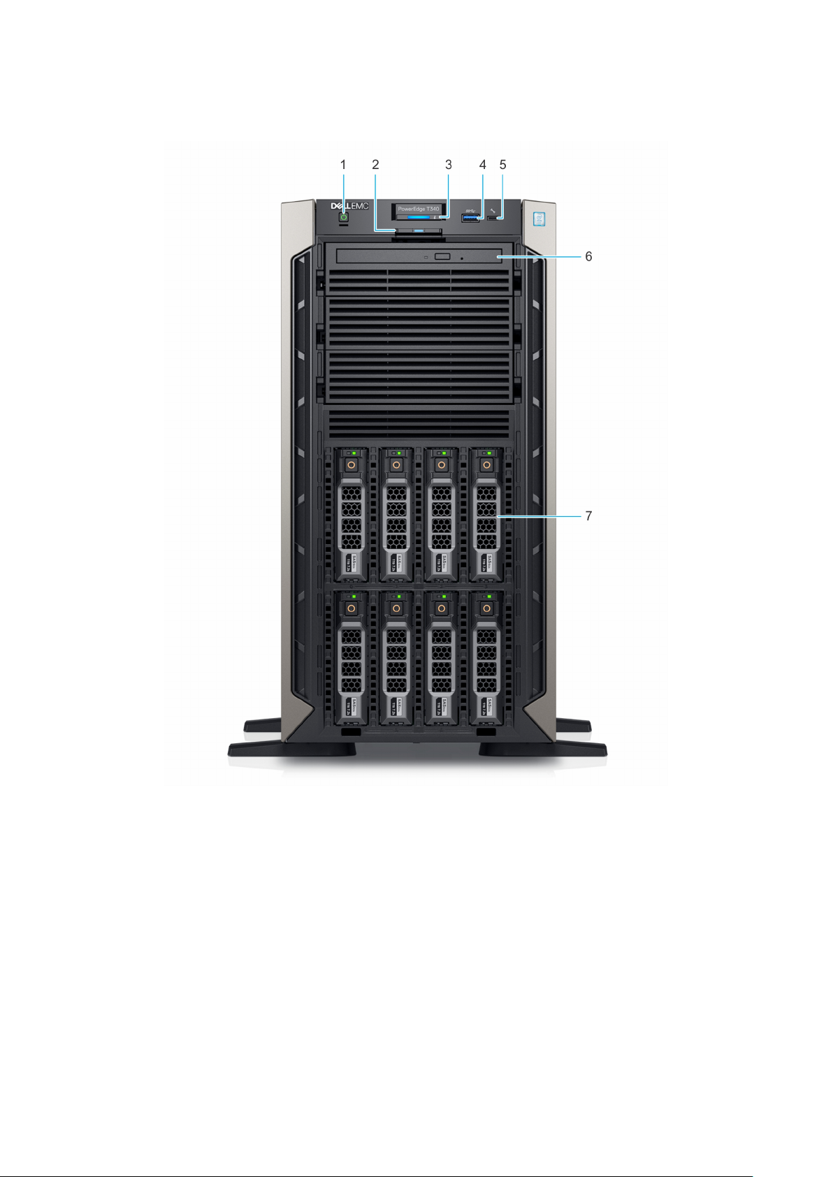
Front view of the system
Figure 1. Front view of 8 x 3.5-inch drive system
Power button 2. Information tag
1.
3. System health and system ID indicator 4. USB 3.0 port
5. iDRAC direct micro USB port 6. Optical drive (optional)
7. Drive (8)
8 Dell EMC PowerEdge T340 system overview
Page 9
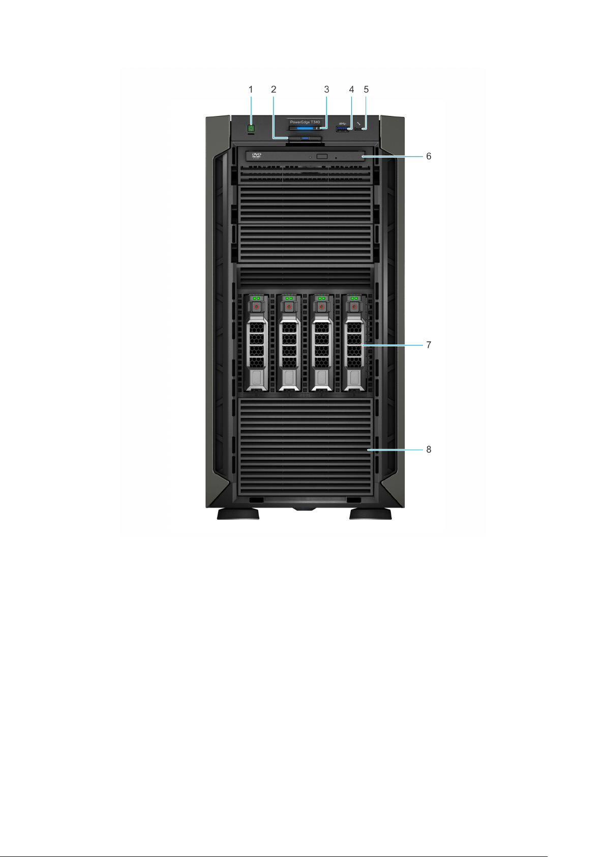
Figure 2. Front view of 4 x 3.5-inch drive system
Power button 2. Information tag
1.
3. System health and system ID indicator 4. USB 3.0 port
5. iDRAC direct micro USB port 6. Optical drive (optional)
7. Drive (4) 8. Four-slot drive blank
For more information about the ports, see the Dell EMC PowerEdge T340 Technical Specifications Guide.
Dell EMC PowerEdge T340 system overview
9
Page 10
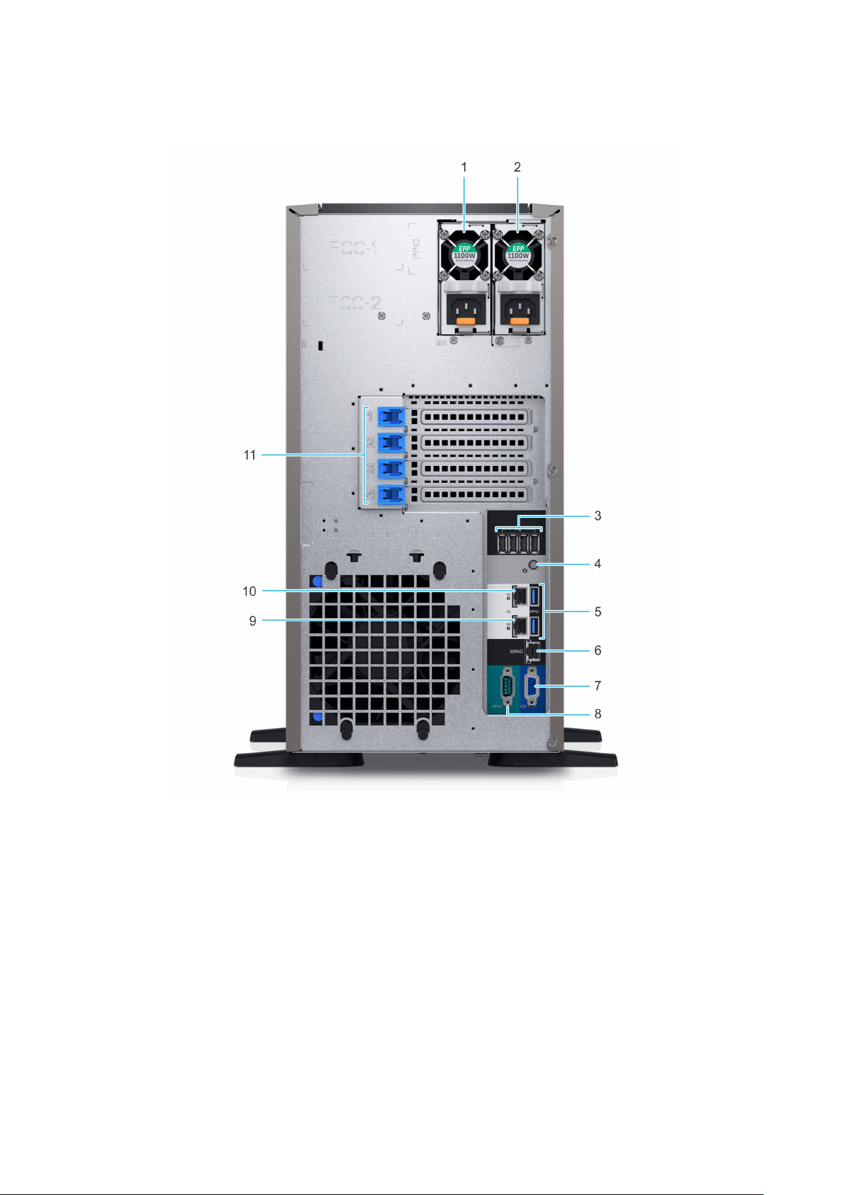
Rear view of the system
Figure 3. Rear view of 8 x 3.5-inch drive system
Power supply unit (PSU 1) 2. Power supply unit (PSU 2)
1.
3. USB 2.0 port (4) 4. System Identification button
5. USB 3.0 port (2) 6. iDRAC dedicated NIC port
7. VGA port 8. Serial port
9. NIC port (Gb1) 10. NIC port (Gb2)
11. PCIe expansion card slots (4)
10 Dell EMC PowerEdge T340 system overview
Page 11
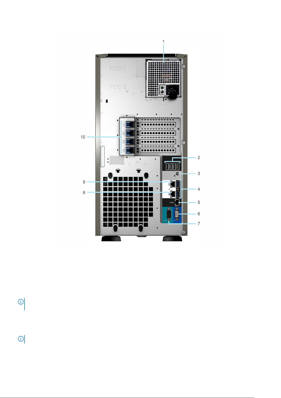
Figure 4. Rear view of 4 x 3.5-inch drive system
Cabled power supply unit (PSU) 2. USB 2.0 port (4)
1.
3. System identification button 4. USB 3.0 port (2)
5. iDRAC dedicated NIC port 6. VGA port
7. Serial port 8. NIC port (Gb1)
9. NIC port (Gb2) 10. PCIe expansion card slots (4)
NOTE: For more information about the ports and connectors, see the Dell EMC PowerEdge T340 Technical Specifications
Guide.
Inside the system
NOTE: Components that are hot swappable are marked orange and touch points on the components are marked blue.
Dell EMC PowerEdge T340 system overview 11
Page 12
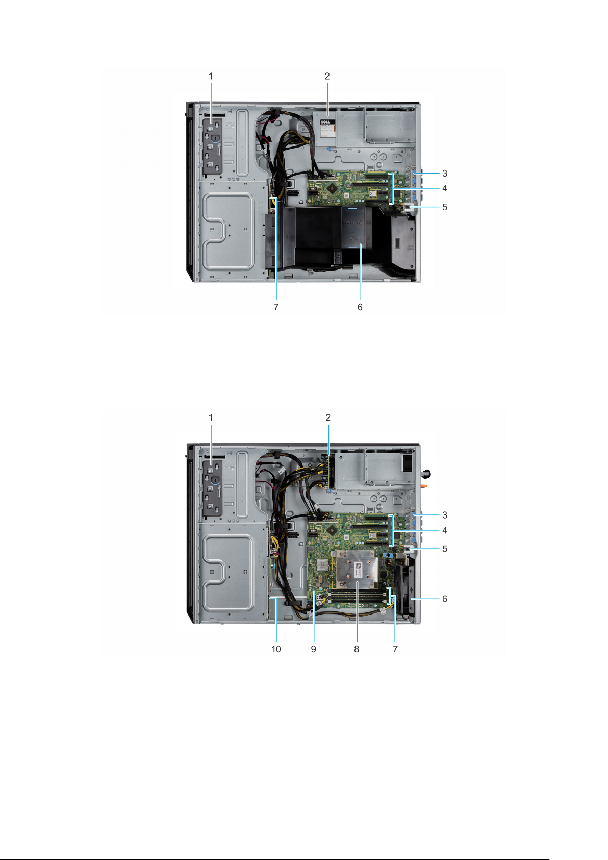
Figure 5. Inside the system with cabled power supply unit (PSU)
1. Optical drive or tape drive 2. Power supply unit (cabled)
3. PCIe Expansion card latch (4) 4. PCIe Expansion card slots (4)
5. Intrusion switch 6. Air shroud
7. Drive backplane
Figure 6. Inside the system with redundant power supply unit (PSU)
1.
Optical drive or tape drive 2. Power interposer board
3. PCIe Expansion card latch (4) 4. PCIe Expansion card slots (4)
5. Intrusion switch 6. Fan
7. Memory module socket (4) 8. Processor and heat sink
9. System board 10. Drive backplane
12 Dell EMC PowerEdge T340 system overview
Page 13
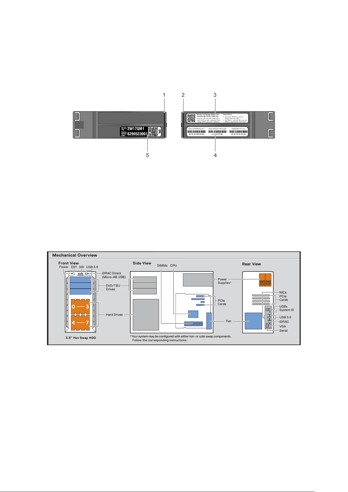
Locating the information tag of your system
Your system is identified by a unique Express Service Code and Service Tag number. You can view the Express Service Code
and Service Tag by pulling out the information tag located on the front of the system. Alternatively, the information may be on
the Mini Enterprise Service Tag (MEST) label on the chassis, on the rear of the system. This information is used by Dell to route
support calls to the appropriate personnel.
Figure 7. Locating Service Tag of your system
1. Information tag (top view) 2. Information tag (back view)
3. OpenManage Mobile (OMM) label 4. iDRAC MAC address and iDRAC secure password label
5. Service Tag, Express Service Code, QRL label
System information label
PowerEdge T340 – System information label
Figure 8. Mechanical overview
Dell EMC PowerEdge T340 system overview
13
Page 14
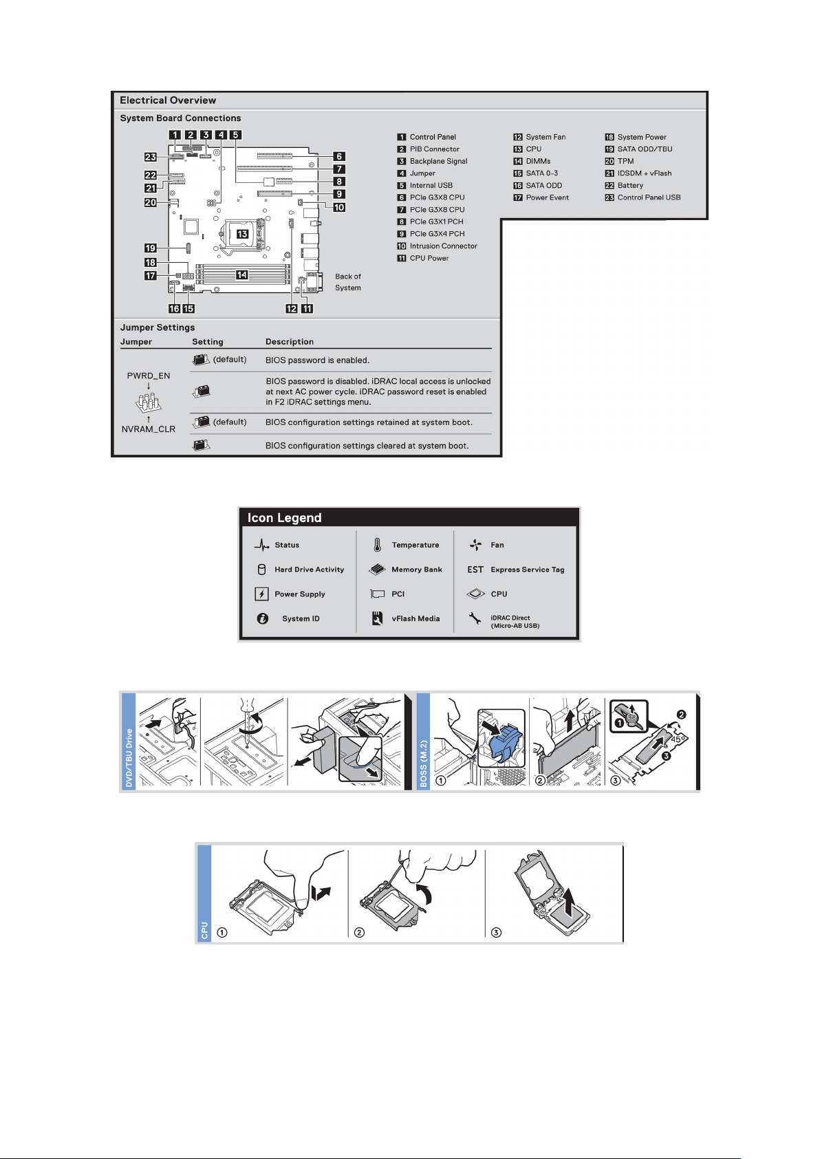
Figure 9. Electrical overview
Figure 10. Icon legend
Figure 11. DVD and BOSS installation
Figure 12. CPU installation
14
Dell EMC PowerEdge T340 system overview
Page 15
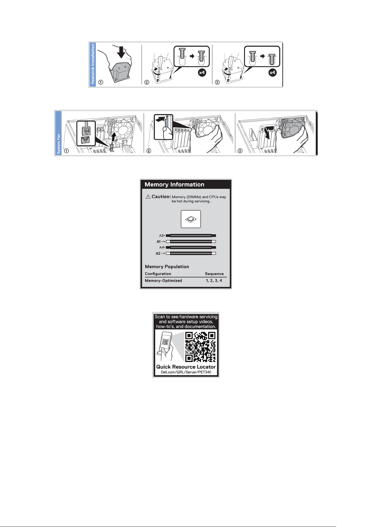
Figure 13. Heat sink installation
Figure 14. Internal cooling fan installation
Figure 15. Memory population
Figure 16. Quick resource locator
Dell EMC PowerEdge T340 system overview
15
Page 16

Initial system setup and configuration
Topics:
• Setting up your system
iDRAC configuration
•
• Options to install the operating system
Setting up your system
Perform the following steps to set up your system:
Steps
1. Unpack the system.
2. Connect the peripherals to the system.
3. Connect the system to its electrical outlet.
4. Power on the system by pressing the power button or by using iDRAC.
5. Power on the attached peripherals.
For more information about setting up your system, see the Getting Started Guide that shipped with your system.
3
iDRAC configuration
The Integrated Dell Remote Access Controller (iDRAC) is designed to make system administrators more productive and improve
the overall availability of Dell systems. iDRAC alerts administrators about system issues and enables them to perform remote
system management. This reduces the need for physical access to the system.
Options to set up iDRAC IP address
To enable communication between your system and iDRAC, you must first configure the network settings based on your
network infrastructure.
NOTE: For static IP configuration, you must request for it at the time of purchase.
This option is set to DHCP by Default. You can set up the IP address by using one of the following interfaces:
Interfaces
iDRAC Settings
utility
Dell Deployment
Toolkit
Dell Lifecycle
Controller
NOTE: To access iDRAC, ensure that you connect the ethernet cable to the iDRAC9 dedicated network port. You can also
access iDRAC through the shared LOM mode, if you have opted for a system that has the shared LOM mode enabled.
Document/Section
Dell Integrated Dell Remote Access Controller User's Guide at www.dell.com/poweredgemanuals
Dell Deployment Toolkit User’s Guide at www.dell.com/openmanagemanuals > OpenManage Deployment
Toolkit
Dell Lifecycle Controller User’s Guide at www.dell.com/poweredgemanuals
16 Initial system setup and configuration
Page 17

Log in to iDRAC
You can log in to iDRAC as:
● iDRAC user
● Microsoft Active Directory user
● Lightweight Directory Access Protocol (LDAP) user
If you have opted for secure default access to iDRAC, you must use the iDRAC secure default password available on the system
Information tag. If you have not opted for secure default access to iDRAC, then use the default user name and password –root
and ca lvi n. You can also log in by using your Single Sign-On or Smart Card.
NOTE: You must have the iDRAC credentials to log in to iDRAC.
NOTE: Ensure that you change the default username and password after setting up the iDRAC IP address.
For more information about logging in to the iDRAC and iDRAC licenses, see the latest Integrated Dell Remote Access Controller
User's Guide at www.dell.com/poweredgemanuals.
You can also access iDRAC by using RACADM. For more information, see the RACADM Command Line Interface Reference
Guide at www.dell.com/poweredgemanuals.
Options to install the operating system
If the system is shipped without an operating system, install a supported operating system by using one of the following
resources:
Table 1. Resources to install the operating system
Resources Location
iDRAC www.dell.com/idracmanuals
Lifecycle Controller www.dell.com/idracmanuals > Lifecycle Controller
OpenManage Deployment Toolkit www.dell.com/openmanagemanuals > OpenManage
Deployment Toolkit
Dell certified VMware ESXi www.dell.com/virtualizationsolutions
Installation and How-to videos for supported operating
systems on PowerEdge systems
Supported Operating Systems for Dell EMC PowerEdge
systems
Methods to download firmware and drivers
You can download the firmware and drivers by using any of the following methods:
Table 2. Firmware and drivers
Methods Location
From the Dell EMC support site www.dell.com/support/home
Using Dell Remote Access Controller Lifecycle Controller
(iDRAC with LC)
www.dell.com/idracmanuals
Using Dell Repository Manager (DRM) www.dell.com/openmanagemanuals > Repository Manager
Using Dell OpenManage Essentials www.dell.com/openmanagemanuals > OpenManage Essentials
Using Dell OpenManage Enterprise www.dell.com/openmanagemanuals > OpenManage
Enterprise
Using Dell Server Update Utility (SUU) www.dell.com/openmanagemanuals > Server Update Utility
Initial system setup and configuration 17
Page 18

Table 2. Firmware and drivers (continued)
Methods Location
Using Dell OpenManage Deployment Toolkit (DTK) www.dell.com/openmanagemanuals > OpenManage
Deployment Toolkit
Using iDRAC virtual media www.dell.com/idracmanuals
Downloading drivers and firmware
Dell EMC recommends that you download and install the latest BIOS, drivers, and systems management firmware on your
system.
Prerequisites
Ensure that you clear the web browser cache before downloading the drivers and firmware.
Steps
1. Go to www.dell.com/support/home.
2. In the Drivers & Downloads section, type the Service Tag of your system in the Enter a Service Tag or product ID box,
and then click Submit.
NOTE: If you do not have the Service Tag, select Detect Product to allow the system to automatically detect the
Service Tag, or click View products, and navigate to your product.
3. Click Drivers & Downloads.
The drivers that are applicable to your system are displayed.
4. Download the drivers to a USB drive, CD, or DVD.
18
Initial system setup and configuration
Page 19

Installing and removing system components
Topics:
• Safety instructions
Before working inside your system
•
• After working inside your system
• Recommended tools
• Front bezel
• System feet
• Caster wheels – optional
• System cover
• Air shroud
• Intrusion switch
• Drives
• Optical drive and tape drives
• Drive backplane
• Backplane cable routing
• Four-slot drive blank
• System memory
• Cooling fan
• Optional internal USB memory key
• Expansion cards
• M.2 SSD module
• Optional IDSDM or vFlash module
• Processor and heat sink
• Power supply unit
• Power interposer board
• System battery
• System board
• Trusted Platform Module
• Control panel
4
Safety instructions
NOTE:
Whenever you need to lift the system, get others to assist you. To avoid injury, do not attempt to lift the system by
yourself.
WARNING: Opening or removing the system cover while the system is powered on may expose you to a risk of
electric shock.
CAUTION: Do not operate the system without the cover for a duration exceeding five minutes. Operating the
system without the system cover can result in component damage.
CAUTION: Many repairs may only be done by a certified service technician. You should only perform
troubleshooting and simple repairs as authorized in your product documentation, or as directed by the online or
telephone service and support team. Damage due to servicing that is not authorized by Dell is not covered by
your warranty. Read and follow the safety instructions that are shipped with your product.
CAUTION: To ensure proper operation and cooling, all bays in the system and system fans must be always
populated with a component or a blank.
Installing and removing system components 19
Page 20

NOTE: It is recommended that you always use an antistatic mat and antistatic strap while working on components inside
the system.
Before working inside your system
Prerequisites
Follow the safety guidelines listed in Safety instructions.
Steps
1. Power off the system and all attached peripherals.
2. Disconnect the system from the electrical outlet, and disconnect the peripherals.
3. Remove the system cover.
After working inside your system
Prerequisites
Follow the safety guidelines listed in Safety instructions on page 19.
Steps
1. Install the system cover.
2. Place the system upright on a flat, stable surface.
3. Reconnect the peripherals and connect the system to the electrical outlet.
4. Power on the attached peripherals and then power on the system.
Recommended tools
You need the following tools to perform the removal and installation procedures:
● Key to the bezel lock
The key is required only if your system includes a bezel.
● Phillips #1 screwdriver
● Phillips #2 screwdriver
● 5mm hex nut screwdriver
● Plastic scribe
● Wrist grounding strap connected to the ground
●
ESD mat
Front bezel
Removing the front bezel
Prerequisites
1. Follow the safety guidelines listed in Safety instructions.
2. Keep the bezel key handy.
Steps
1. Unlock the bezel.
20
Installing and removing system components
Page 21
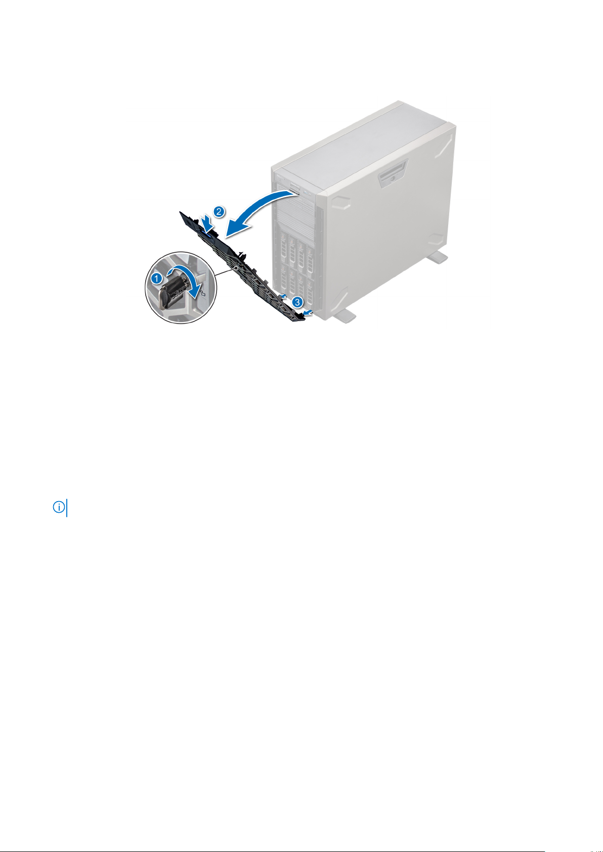
2. Press the blue release latch at the top of the bezel to release the bezel from the system.
3. Unhook the bezel tabs from the slots at the bottom, and lift the bezel.
Figure 17. Removing the front bezel
Next steps
1. Replace the front bezel.
Installing the front bezel
Prerequisites
1. Follow the safety guidelines listed in Safety instructions.
2. Locate and remove the bezel key.
NOTE: The bezel key is part of the bezel package.
Steps
1. Align and insert the bezel tabs into the slots in the system.
2. Press the release latch, and push the bezel toward the system until the bezel locks into place.
3. Lock the bezel.
Installing and removing system components
21
Page 22
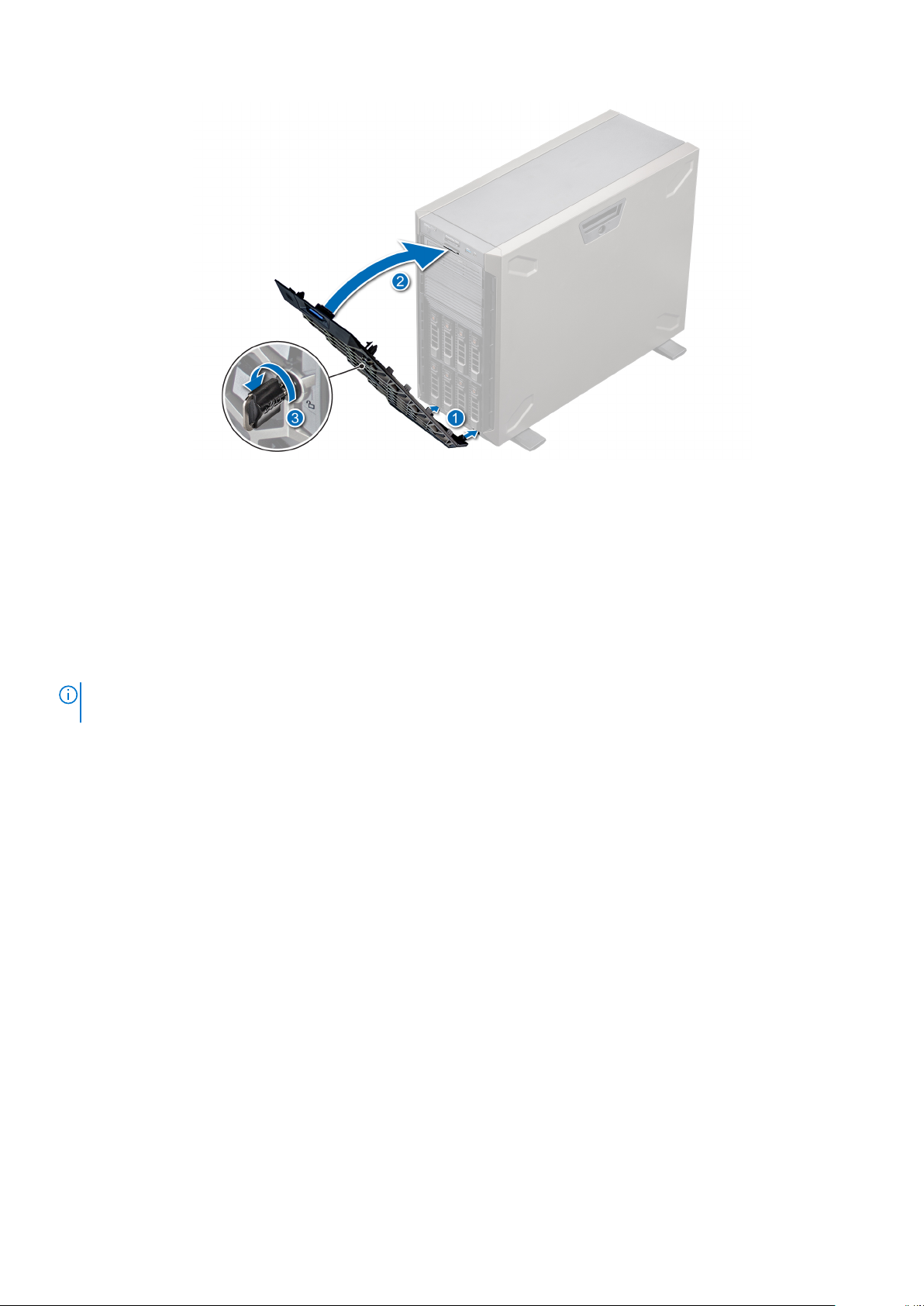
Figure 18. Installing the front bezel
System feet
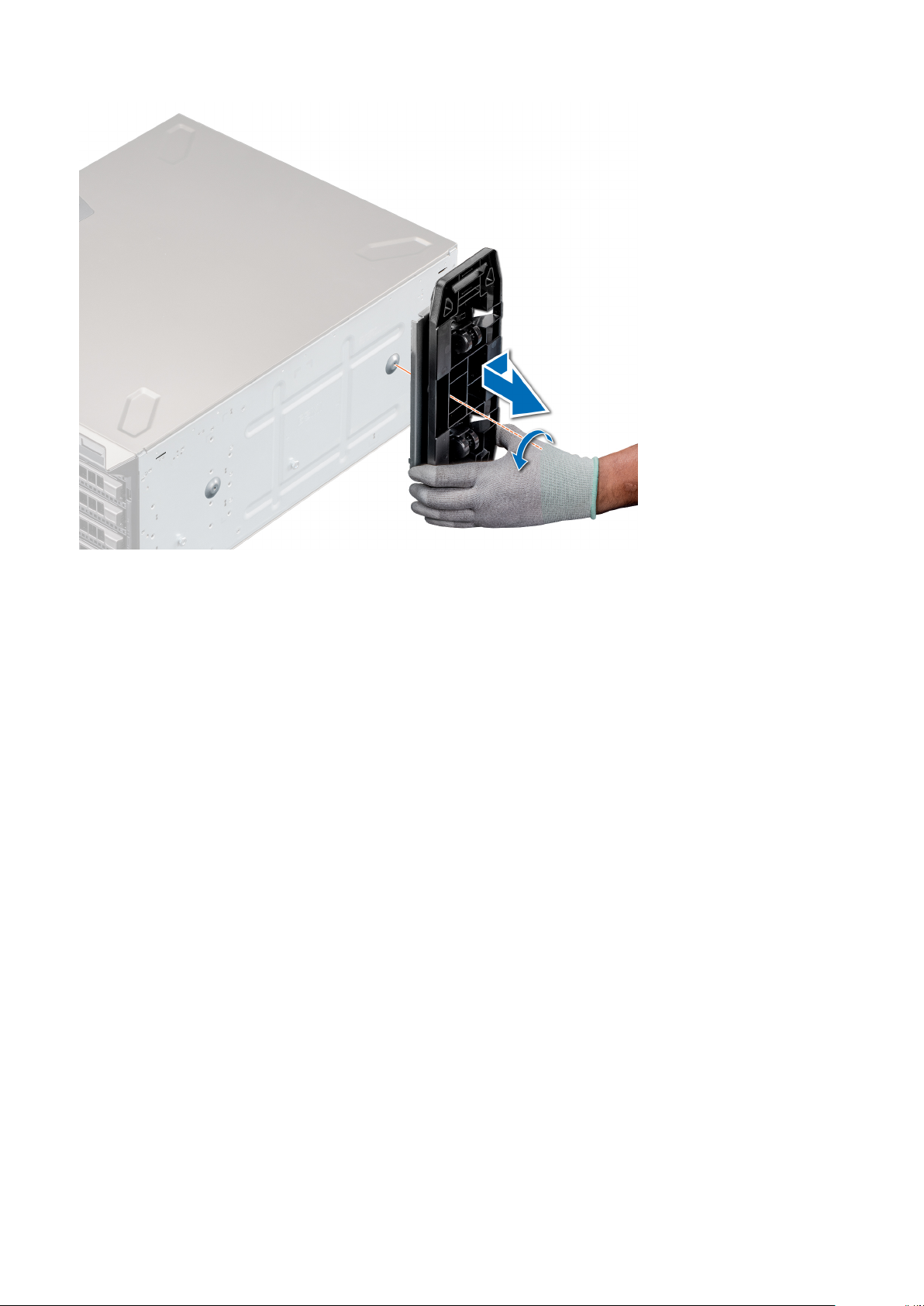
Removing the system feet
Prerequisites
NOTE:
It is recommended that you remove the system feet only when you are replacing the system feet with the wheel
assembly.
1. Follow the safety guidelines listed in Safety instructions..
2. Place the system on its side on a flat, stable surface.
3. Rotate the system feet inward.
Steps
1. Using the Phillips #2 screwdriver, remove the screw that secures the foot to the base of the system.
2. Repeat the preceding step to remove the remaining system feet.
22
Installing and removing system components
Page 23

Figure 19. Removing the system feet
Next steps
1. Replace the system feet or install the caster wheels.
Installing the system feet
Prerequisites
CAUTION:
might tip over and cause injury to the user or damage to the system.
1. Follow the safety guidelines listed in Safety instructions.
2. Place the system on its side on a flat, stable surface.
Steps
1. Align the three tabs on the system foot with the three slots on the base of the system.
2. Using the Phillips #2 screwdriver, secure the screw that secures the foot to the base of the system.
3. Repeat the above steps to install the remaining system feet.
Install the feet on a stand-alone tower system to provide stability to the system. An unstable system
Installing and removing system components
23
Page 24
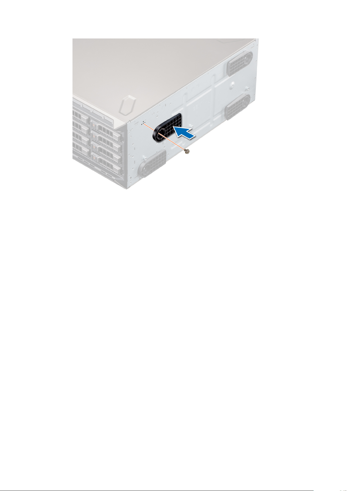
Figure 20. Installing the system feet
Next steps
1. Place the system upright on a flat, stable surface, and rotate the system feet outward.
2. Follow the procedure listed in After working inside your system.
Caster wheels – optional
Removing caster wheels
Prerequisites
1. Follow the safety guidelines listed in Safety instructions.
2. Place the system on its side on a flat, stable surface.
Steps
1. Using the Phillips #2 screwdriver, loosen the captive screw that secures the front wheel unit to the base of the system.
2. Push the front wheel unit toward the rear of the system to release the retention hooks, and pull out the front wheel unit.
3. Loosen the screw that secures the back wheel unit to the base of the system.
4. Push the rear wheel unit toward the front of the system to release the retention hooks, and pull out the rear wheel unit.
24
Installing and removing system components
Page 25
Next steps
1. Replace the caster wheels or replace the system feet, as applicable.
Installing caster wheels
Prerequisites
1. Follow the safety guidelines listed in Safety instructions.
2. Place the system on its side on a flat, stable surface.
3. If installed, remove the system feet.
Steps
1. Align the two retention hooks on the rear wheel unit with the two slots on the base of the system, and insert the hooks into
the slots.
2. Push the rear wheel unit toward the back of the system and using a Phillips #2 screwdriver secure the unit in place using a
single screw.
3. Align the two retention hooks on the front wheel unit with the two slots on the base of the system, and insert the hooks into
the slots.
4. Push the front wheel unit toward the front of the system and using a Phillips #2 screwdriver secure the unit in place using a
single screw.
Installing and removing system components
25
Page 26
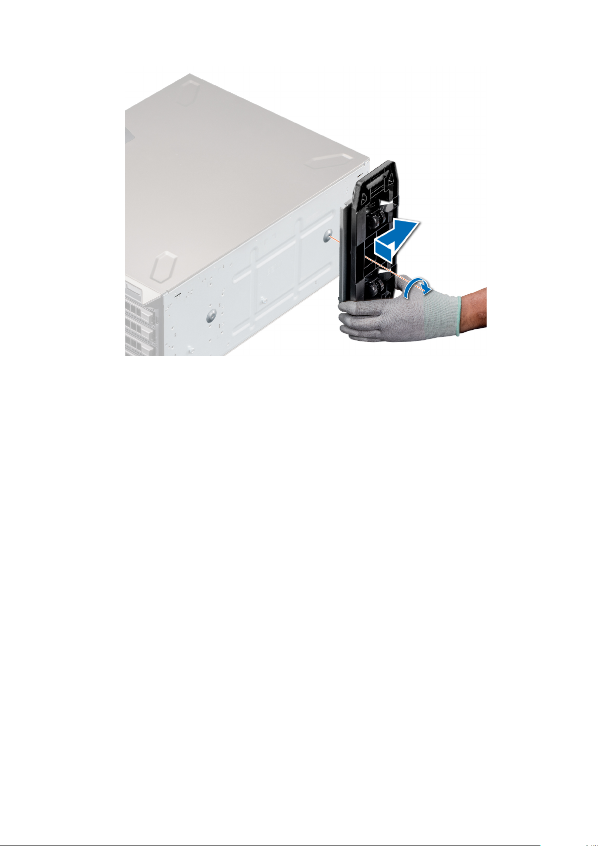
Figure 21. Installing caster wheels
Next steps
1. Follow the procedure listed in After working inside your system.
System cover
Removing the system cover
Prerequisites
1. Follow the safety guidelines listed in Safety instructions.
2. Power off the system and all attached peripherals.
3. Disconnect the system from the electrical outlet and disconnect the peripherals.
4. Place the system on a flat, stable surface.
5. Remove the front bezel.
Steps
1. Use a 1/4-inch flat head or a Phillips #2 screwdriver to turn the cover release latch counterclockwise to the unlock position.
2. Press the cover release latch, and remove the system cover.
26
Installing and removing system components
Page 27
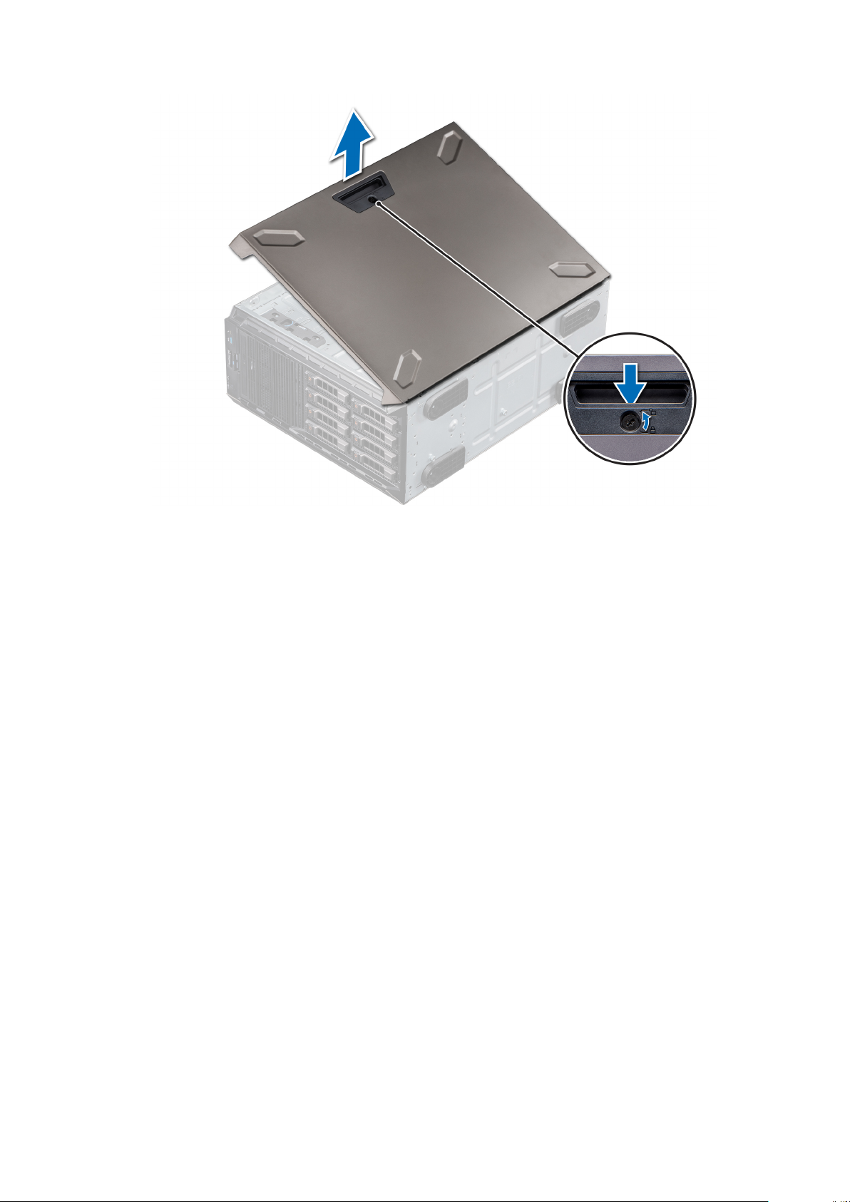
Figure 22. Removing the system cover
Installing the system cover
Prerequisites
1. Follow the safety guidelines listed in Safety instructions.
2. Remove the front bezel.
3. Power off the system and all attached peripherals.
4. Disconnect the system from the electrical outlet and disconnect the peripherals.
5. Ensure that all internal cables are connected and placed out of the way and no tools or extra parts are left inside the system.
Steps
1. Align the tabs on the system cover with the slots on the system.
2. Press the cover release latch, and push the cover toward the system until the latch locks into place.
3. Using a 1/4-inch flat head or a Phillips #2 screwdriver, rotate the cover release latch lock clockwise to the locked position.
Installing and removing system components
27
Page 28
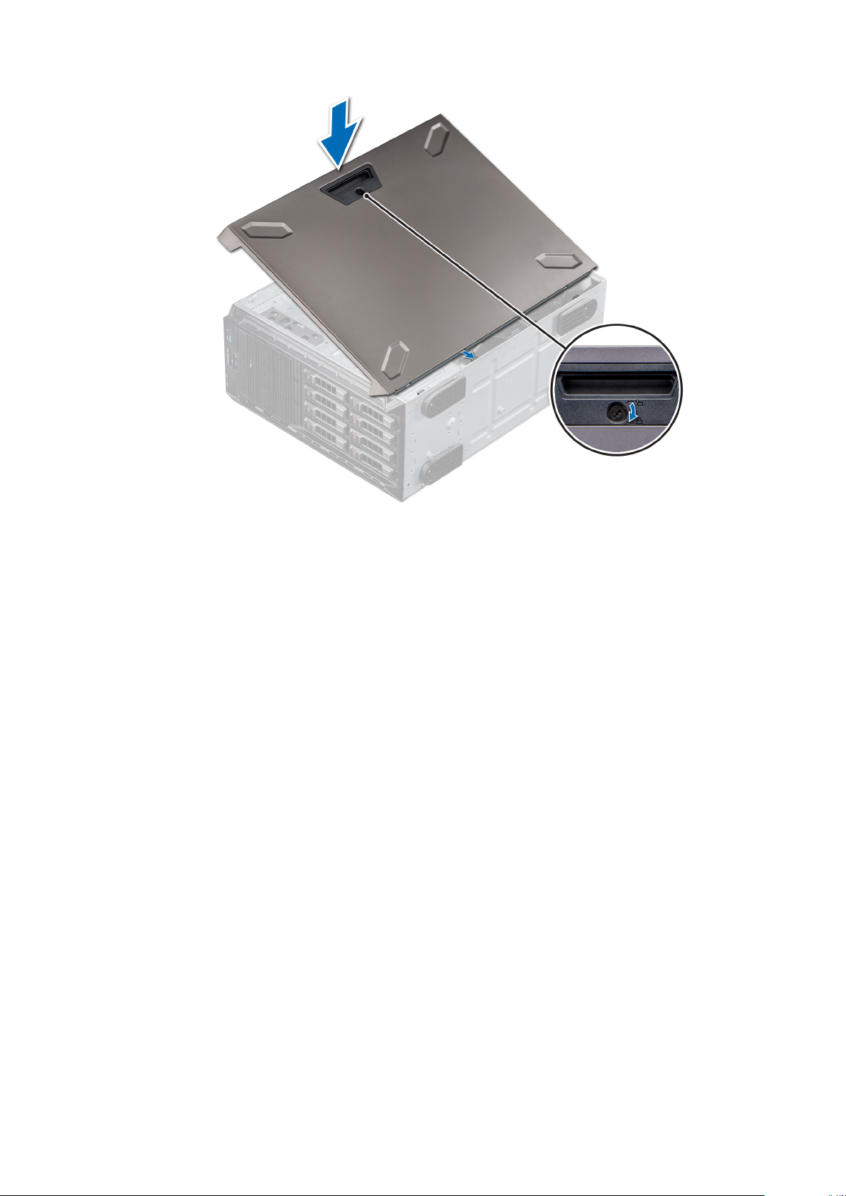
Figure 23. Installing the system cover
Next steps
1. Place the system upright on its feet on a flat, stable surface.
2. Install the front bezel.
3. Reconnect the peripherals, and connect the system to the electrical outlet.
4. Power on the system and all attached peripherals.
28
Installing and removing system components
Page 29
Air shroud
Removing the air shroud
Prerequisites
CAUTION: Never operate your system with the air shroud removed. The system may get overheated quickly,
resulting in shutdown of the system and loss of data.
1. Follow the safety guidelines listed in Safety instructions.
2. Follow the procedure listed in Before working inside your system.
3. Remove the system cover.
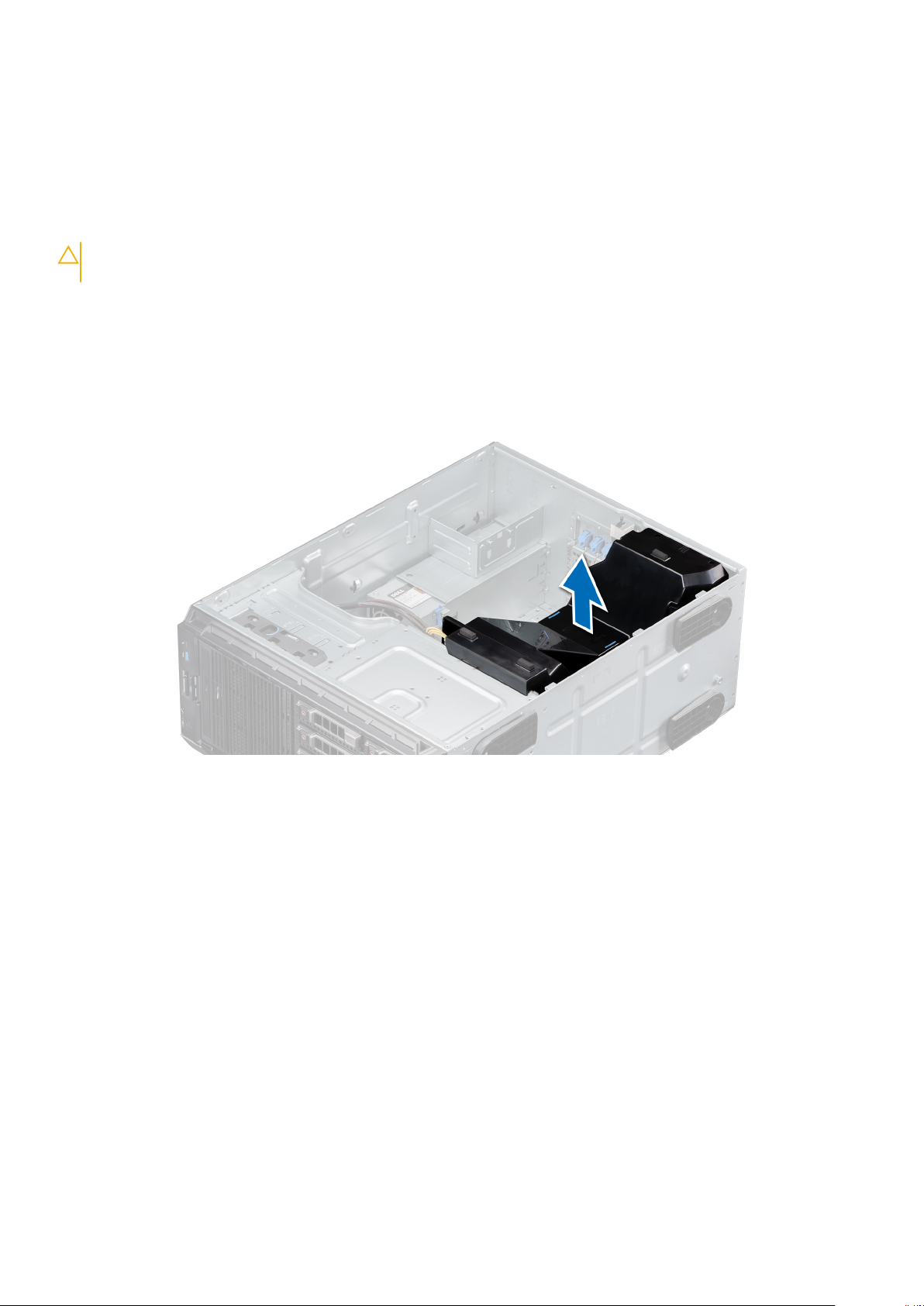
Steps
Holding the blue touch points, lift the air shroud out of the system.
Figure 24. Removing the air shroud
Next steps
1. Replace the air shroud.
Installing the air shroud
Prerequisites
1. Follow the safety guidelines listed in Safety instructions.
2. Follow the procedure listed in Before working inside your system.
3. If applicable, route the cables inside the system along the system wall and secure the cables by using the cable-securing
bracket.
Steps
1. Align the tabs on the air shroud with the slots on the system.
2. Lower the air shroud into the system until it is firmly seated.
Installing and removing system components
29
Page 30
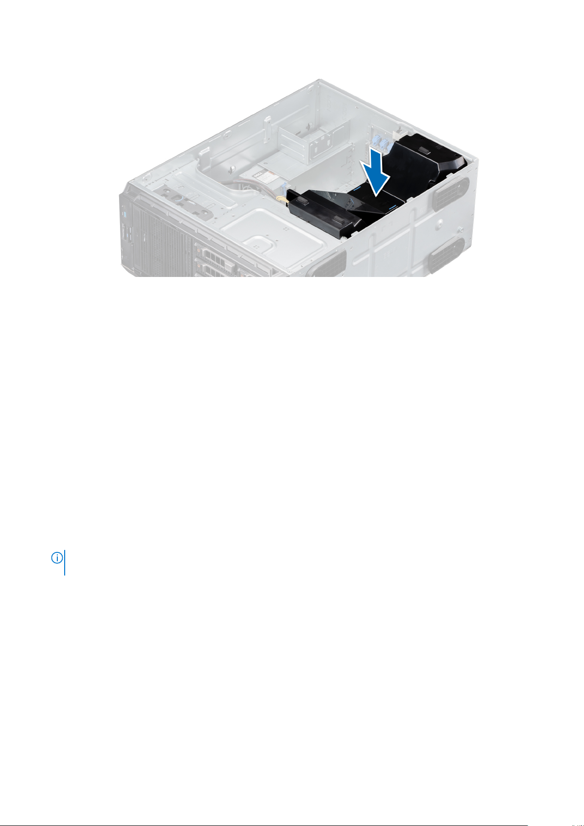
Figure 25. Installing the air shroud
Next steps
1. Install the system cover.
2. Follow the procedure listed in Before working inside your system.
Intrusion switch
Removing the intrusion switch
Prerequisites
1. Follow the safety guidelines listed in Safety instructions.
2. Follow the procedure listed in Before working inside your system.
3. Keep the plastic scribe ready.
Steps
1. Disconnect the intrusion switch cable connector from the system board.
NOTE:
Observe the routing of the cable as you remove it from the system. Route the cable properly when you replace it
to prevent the cable from being pinched or crimped.
2. Using the plastic scribe, slide the intrusion switch out of the intrusion switch slot.
30
Installing and removing system components
Page 31

Figure 26. Removing the intrusion switch
Next steps
1. Replace the intrusion switch.
Installing the intrusion switch
Prerequisites
1. Follow the safety guidelines listed in Safety instructions.
2. Follow the procedure listed in Before working inside your system.
Steps
1. Align and slide the intrusion switch into the slot in the system.
2. Connect the intrusion switch cable connector to the intrusion switch connector on the system board.
Figure 27. Installing the intrusion switch
Installing and removing system components
31
Page 32

Next steps
1. Install the air shroud.
2. Follow the procedure that is listed in After working inside your system.
Drives
Removing a drive blank
Prerequisites
1. Follow the safety guidelines listed in Safety instructions.
2. Follow the procedure listed in Before working inside your system.
3. Remove the front bezel.
CAUTION: To maintain proper system cooling, drive blanks must be installed in all empty drive slots.
CAUTION: Mixing drive blanks from previous generations of PowerEdge servers is not supported.
Steps
Press the release tab, and slide the drive blank out.
Figure 28. Removing a drive blank
NOTE: The procedure to remove a 2.5-inch or a 3.5-inch drive blank is the same.
Next steps
1. Replace the drive or a drive blank.
Installing a drive blank
Prerequisites
1. Follow the safety guidelines listed in Safety instructions.
2. Follow the procedure in Before working inside your system.
3. Remove the front bezel.
CAUTION: To maintain proper system cooling, drive blanks must be installed in all empty drive slots.
CAUTION: Mixing drive blanks from previous generations of PowerEdge servers is not supported.
32 Installing and removing system components
Page 33

Steps
Slide the drive blank into the drive slot until the release tab clicks into place.
Figure 29. Installing a drive blank
Next steps
1. Replace the front bezel.
2. Follow the procedure listed in After working inside your system.
Removing a drive carrier
Prerequisites
1. Follow the safety guidelines listed in Safety instructions.
2. Remove the front bezel.
3. Using the management software, prepare the drive for removal.
If the drive is online, the green activity or fault indicator flashes while the drive is turning off. When the drive indicators are
off, the drive is ready for removal. For more information, see the storage controller documentation.
CAUTION:
for the storage controller card to ensure that the host adapter is configured correctly to support drive
removal and insertion.
CAUTION: To prevent data loss, ensure that your operating system supports drive installation. See the
documentation supplied with your operating system.
Steps
1. Press the release button to open the drive carrier release handle.
2. Holding the handle, slide the drive carrier out of the drive slot.
NOTE:
system cooling.
Before attempting to remove or install a drive while the system is running, see the documentation
If you are not replacing the drive immediately, install a drive blank in the empty drive slot to maintain proper
Installing and removing system components 33
Page 34

Figure 30. Removing a drive carrier
Next steps
Replace the drive or a drive blank.
Installing the drive carrier
Prerequisites
CAUTION:
storage controller card to ensure that the host adapter is configured correctly to support drive removal and
insertion.
CAUTION: Combining SAS and SATA drives in the same RAID volume is not supported.
CAUTION: When installing a drive, ensure that the adjacent drives are fully installed. Inserting a drive carrier
and attempting to lock its handle next to a partially installed carrier can damage the partially installed carrier's
shield spring and make it unusable.
NOTE: Ensure that the drive carrier's release handle is in the open position before inserting the carrier into the slot.
CAUTION: To prevent data loss, ensure that your operating system supports hot-swap drive installation. See the
documentation supplied with your operating system.
Before removing or installing a drive while the system is running, see the documentation for the
CAUTION: When a replacement hot swappable drive is installed and the system is powered on, the drive
automatically begins to rebuild. Ensure that the replacement drive is blank or contains data that you wish to
overwrite. Any data on the replacement drive is immediately lost after the drive is installed.
1. Follow the safety guidelines listed in Safety instructions.
2. Follow the procedure listed in Before working inside your system.
3. Remove the front bezel.
4. If installed, remove a drive blank.
Steps
1. Press the release button on the front of the drive carrier to open the release handle.
2. Insert the drive carrier into the drive slot and push until the drive connects with the backplane.
3. Close the drive carrier release handle to lock the drive in place.
34
Installing and removing system components
Page 35

NOTE: The procedure to install a 2.5-inch or a 3.5-inch drive are the same.
Figure 31. Installing a drive carrier
Next steps
1. Install the front bezel.
2. Follow the procedure listed in After working inside your system.
Removing the drive from the drive carrier
Prerequisites
1. Follow the safety guidelines listed in Safety instructions.
CAUTION: Mixing drive carriers from previous generations of PowerEdge servers is not supported.
2. Follow the procedure listed in Before working inside your system.
3. Remove the front bezel.
4. Remove the drive carrier.
Steps
1. Using a Phillips #1 screwdriver, remove the screws from the slide rails on the drive carrier.
NOTE:
If the hard drive or SSD carrier has Torx screw, use Torx 6 (for 2.5-inch drive) or Torx 8 (for 3.5-inch drive)
screw driver to remove the drive.
2. Lift the drive out of the drive carrier.
Installing and removing system components
35
Page 36

Figure 32. Removing the drive from the drive carrier
Next steps
1. Replace the drive into the drive carrier.
Installing the drive into the drive carrier
Prerequisites
1. Follow the safety guidelines listed in Safety instructions.
2. Follow the procedure listed in Before working inside your system.
3. Remove the front bezel.
4. Remove the drive carrier.
CAUTION: Mixing drive carriers from other generations of PowerEdge servers is not supported.
Steps
1. Insert the drive into the drive carrier with the connector end of the drive towards the back of the carrier.
2. Align the screw holes on the drive with the screws holes on the drive carrier. When aligned correctly, the back of the drive is
flush with the back of the drive carrier.
3. Using a Phillips #1 screwdriver, replace the screws to secure the drive to the drive carrier.
NOTE:
If the hard drive or SSD carrier has Torx screw, use Torx 6 (for 2.5-inch drive) or Torx 8 (for 3.5-inch drive)
screw driver to install the drive.
NOTE: When installing a drive into the drive carrier, ensure that the screws are torqued to 4 in-pounds.
NOTE: Use the screws shipped with the drive carrier to secure the drive to the drive carrier.
36 Installing and removing system components
Page 37

Figure 33. Installing a drive into the drive carrier
Next steps
1. Replace the drive carrier.
2. Install the front bezel.
3. Follow the procedure listed in After working inside your system.
Removing a 2.5-inch drive from the 3.5-inch drive adapter
Prerequisites
1. Follow the safety guidelines listed in Safety instructions.
2. Follow the procedure listed in Before working inside your system.
3. Remove 3.5-inch drive adapter from the 3.5-inch drive carrier.
NOTE:
A 2.5 inch hot swappable drive is installed in a 3.5-inch drive adapter, which is then installed in the 3.5-inch hot
swappable drive carrier.
Steps
1. Using a Phillips #1 screwdriver, remove the screws from the side of the 3.5-inch drive adapter.
NOTE: If the 2.5-inch drive has Torx screw, use Torx 6 screwdriver to remove the drive from a 3.5-inch drive adapter.
2. Remove the drive from the 3.5-inch drive adapter.
Installing and removing system components
37
Page 38

Figure 34. Removing a 2.5-inch drive from the 3.5-inch drive adapter
Next steps
Replace a 2.5-inch drive into the 3.5-inch drive adapter.
Installing a 2.5-inch drive into the 3.5-inch drive adapter
Prerequisites
Follow the safety guidelines listed in Safety instructions.
Steps
1. Align the screw holes on the 2.5-inch drive with the screw holes on the 3.5-inch drive adapter.
2. Using a Phillips #1 screwdriver, install the screws to secure the drive to the 3.5-inch drive adapter.
NOTE: If the 2.5-inch drive has Torx screw, use Torx 6 screwdriver to install the drive to a 3.5-inch drive adapter.
38 Installing and removing system components
Page 39

Figure 35. Installing a 2.5-inch drive into the 3.5-inch drive adapter
Next steps
1. Replace a 3.5-inch adapter into the 3.5-inch drive carrier.
2. Follow the procedure listed in After working inside your system.
Removing a 3.5-inch drive adapter from a 3.5-inch drive carrier
Prerequisites
1. Follow the safety guidelines listed in Safety instructions.
2. Follow the procedure listed in Before working inside your system.
3. Remove the 3.5-inch drive carrier from the system.
Steps
1. Remove the screws from the rails on the drive carrier.
NOTE: If the 3.5-inch drive has Torx screw, use Torx 6 screwdriver to remove the drive from a 3.5-inch drive adapter.
2. Lift the 3.5 inch drive adapter out of the drive carrier.
Installing and removing system components
39
Page 40

Figure 36. Removing a 3.5-inch drive adapter from a 3.5-inch drive carrier
Next steps
Replace a 3.5-inch adapter into a 3.5-inch drive carrier.
Installing a 3.5-inch adapter into a 3.5-inch drive carrier
Prerequisites
Follow the safety guidelines listed in Safety instructions.
Steps
1. Insert the 3.5 inch drive adapter into the drive carrier with the connector end of the drive toward the back of the drive
carrier.
2. Align the screw holes on the drive with the holes on the drive carrier.
3. Install the screws to secure the drive to the drive carrier.
NOTE: If the 3.5-inch drive has Torx screw, use Torx 6 screwdriver to install the drive to a 3.5-inch drive adapter.
40 Installing and removing system components
Page 41

Figure 37. Installing a 3.5-inch drive adapter into the 3.5-inch drive carrier
Next steps
1. Replace a 3.5-inch drive carrier into the system.
2. Follow the procedure listed in After working inside your system.
Optical drive and tape drives
Removing the optical or tape drive blank
Prerequisites
NOTE: The procedure to remove the optical drive blank is identical to removing a tape drive blank.
1. Follow the safety guidelines listed in Safety instructions.
2. Follow the procedure listed in Before working inside your system.
3. Remove the front bezel.
Steps
1. Slide the release latch downwards to remove the drive blank.
2. Push the drive blank to slide it out of the drive bay.
Installing and removing system components
41
Page 42

Figure 38. Removing the optical drive or tape drive blank
NOTE: Blanks must be installed on empty optical drive or tape drive slots to maintain FCC certification of the system.
The brackets also keep dust and dirt out of the system and aid in proper cooling and airflow inside the system. Perform
the same steps to install blanks.
Next steps
Replace the optical drive blank, or an optical drive, or a tape drive.
Installing the optical or tape drive blank
Prerequisites
1. Follow the safety guidelines listed in Safety instructions.
2. Remove the front bezel.
Steps
1. Align the guide on the drive blank with the slot on drive bay.
2. Slide the drive into the slot until the latch snaps into place.
42
Installing and removing system components
Page 43

Figure 39. Installing the optical or tape drive blank
Next steps
1. Install the front bezel.
2. Follow the procedure listed in After working inside your system.
Removing the optical drive
Prerequisites
1. Follow the safety guidelines listed in Safety instructions.
2. Follow the procedure listed in Before working inside your system.
3. Remove the front bezel.
Steps
1. Disconnect the power and data cable connectors from the connectors on the optical drive.
NOTE:
Observe the routing of the power and data cable inside the chassis as you remove them from the system board
and the drive. You must route these cables properly when you replace them to prevent them from being pinched or
crimped.
2. To remove the drive, slide the release latch downwards to release the drive.
3. Slide the drive out of the drive bay.
4. If you are not immediately replacing the tape drive, install the blank.
Blanks must be installed on empty optical drive or tape drive slots to maintain FCC certification of the system.
NOTE:
The brackets also keep dust and dirt out of the system and aid in proper cooling and airflow inside the system. Perform
the same steps to install blanks.
Installing and removing system components 43
Page 44

Figure 40. Removing the optical drive
Next steps
1. Replace the optical drive.
2. Follow the procedure listed in After working inside your system.
Installing the optical drive
Prerequisites
1. Ensure that you follow the procedure listed in Safety instructions.
2. Follow the procedure listed in Before working inside your system.
3. Remove the front bezel.
4. If applicable, remove the optical drive blank.
NOTE: The procedure to remove the optical drive blank and the optical drive is similar.
Steps
1. Align the slide the optical drive into the slot until the latch clicks into place.
2. Connect the power and data cable connectors to the connectors on the optical drive.
3. Connect the power and data cable connectors to the backplane and the system board.
NOTE: Route the cables properly to prevent them from being pinched or crimped.
44 Installing and removing system components
Page 45

Figure 41. Installing the optical drive
Next steps
1. Install the front bezel.
2. Follow the procedure listed in After working inside your system.
Removing the tape drive
Prerequisites
1. Follow the safety guidelines listed in Safety instructions.
2. Follow the procedure listed in Before working inside your system.
3. Remove the front bezel.
Steps
1. Disconnect the power and data cable connectors from the connectors on the tape drive.
NOTE:
Observe the routing of the power and data cable connectors inside the chassis as you remove them from the
system board and the drive. You must route these cables properly when you replace them to prevent them from being
pinched or crimped.
2. Using the Phillips #2 screwdriver, remove the screw that secures the tape drive.
3. Push the release latch to release the drive.
4. Slide the drive out of the drive bay.
5. If you are not immediately replacing the tape drive, install the blank.
Blanks must be installed on empty tape drive slots to maintain FCC certification of the system. The brackets also
NOTE:
keep dust and dirt out of the system and aid in proper cooling and airflow inside the system. Perform the same steps to
install blanks.
Installing and removing system components 45
Page 46

Figure 42. Removing the tape drive
Next steps
1. Replace the tape drive.
2. Follow the procedure listed in After working inside your system.
Installing the tape drive
Prerequisites
1. Ensure that you follow the procedure listed in Safety instructions.
2. Follow the procedure listed in Before working inside your system.
3. Remove the front bezel.
4. If applicable, remove the tape drive blank.
NOTE: The procedure to remove the tape drive blank and the tape drive is similar.
Steps
1. Align and slide the tape drive into the tape drive bay until it clicks into place.
2. Using the Phillips #2 screwdriver, secure the tape drive to the drive bay.
3. Connect the power and data cable connectors to the connectors on the tape drive.
4. Connect the power and data cable connectors to the backplane and the system board.
NOTE: Route the cables properly to prevent them from being pinched or crimped.
46 Installing and removing system components
Page 47

Figure 43. Installing the tape drive
Next steps
1. Install the front bezel.
2. Follow the procedure listed in After working inside your system.
Drive backplane
Drive backplane details
Your system supports the following backplane configuration:
● x8 SAS/SATA backplane for 3.5-inch drives
NOTE:
The x8 backplane also supports up to eight 2.5-inch (SAS, SATA, or SSD) hot swappable drives that can be
installed in 3.5-inch drive adapters, which can be installed in the 3.5-inch drive carriers.
Installing and removing system components 47
Page 48

Figure 44. x8 SAS/SATA backplane for 3.5-inch drives
1. ODD power connector (P1)
2. Backplane P4 power connector (BP_PWR)
3. Backplane sideband signal connector (BP_SIG)
4. Mini SAS SAS_A0
5. Mini SAS SAS_B0
Removing the drive backplane
Prerequisites
CAUTION:
can replace them in the same location.
1. Follow the safety guidelines listed in Safety instructions.
2. Follow the procedure listed in Before working inside your system.
3. Remove the front bezel.
4. Remove all the drives.
CAUTION:
removing the backplane.
5. Remove the air shroud.
Steps
1. Disconnect the data, signal, and power cables from the backplane.
2. Pull the release pin to disengage the backplane from the system.
3. Lift the backplane out of the system.
Note the number of each drive and temporarily label them before you remove the drive so that you
To prevent damage to the drives and backplane, remove the drives from the system before
48
Installing and removing system components
Page 49

Figure 45. Removing the drive backplane
Next steps
1. Replace a drive backplane.
2. Follow the procedure listed in After working inside your system.
Installing the drive backplane
Prerequisites
1. Follow the safety guidelines listed in Safety instructions.
2. Follow the procedure listed in Before working inside your system.
3. Remove the front bezel..
4. Remove the air shroud.
5. Remove all the drives.
Steps
1. Align the slots on the backplane with the hooks on the system.
2. Lower the drive backplane into the system until the release pin locks in place, securing the drive backplane to the system.
3. Connect the data, signal, and power cables to the backplane.
Installing and removing system components
49
Page 50

Figure 46. Installing the drive backplane
Next steps
1. Install the air shroud.
2. Install the drives.
3. Install the front bezel.
4. Follow the procedure listed in After working inside your system.
Backplane cable routing
Figure 47. Cable routing - 8 x 3.5-inch, SATA drive backplane
50
Installing and removing system components
Page 51

Figure 48. Cable routing - 8 x 3.5-inch SAS/SATA drive backplane with PERC card
Four-slot drive blank
Systems with x8 drive backplanes configured for software RAID support only four drives. The remaining drive slots are preinstalled with the four-slot drive blank, and cannot be upgraded for additional storage.
Removing a four-slot drive blank
Prerequisites
CAUTION: To maintain proper system cooling, all empty drive slots must have drive blanks installed.
1. Follow the safety guidelines listed in Safety instructions.
2. Follow the procedure listed in Before working inside your system.
CAUTION:
before removing the backplane.
CAUTION: Note the slot number of each drive and temporarily label the slots before removing the drives so
that you can replace them in the same locations.
3. Remove the air shroud.
4. Remove all the drives.
5. Remove the drive backplane.
To prevent damage to the drives and backplane, you must remove the drives from the system
Steps
1. Using a screwdriver, push the release tabs on the corners of the blank from inside the system, to unlock the four-slot hard
drive blank from the chassis.
2. From the front of the system, pull the four-slot hard drive blank at the corners until it is free of the hard drive slot.
Installing and removing system components
51
Page 52

Figure 49. Removing a four-slot drive blank
Next steps
1. Replace a four-slot drive blank.
Installing a four-slot drive blank
Prerequisites
1. Follow the safety guidelines listed in Safety instructions.
2. Follow the procedure listed in Before working inside your system.
Steps
1. Locate the drive slots numbered from four to seven.
2. Insert the four-slot drive blank into the drive slot, and push it until the release tabs click into place.
Figure 50. Installing a four-slot drive blank
52
Installing and removing system components
Page 53

Next steps
1. Install the drive backplane.
2. Install the drives.
3. Install the air shroud.
4. Follow the procedure listed in After working inside your system.
System memory
System memory guidelines
The system supports DDR4 unbuffered DIMMs (UDIMMs). System memory holds the instructions that are executed by the
processor.
Your system contains 4 memory sockets. Two memory channels are allocated to the processor.
Memory channels are organized as follows:
Figure 51. System memory view
Table 3. Memory channels
Processor Channel 0 Channel 1
Processor 1 Slots A1, A3 Slots A2, A4
Installing and removing system components 53
Page 54

The following table shows the memory populations and operating frequencies for the supported configurations:
Table 4. Memory population
DIMM Type DIMMs
Populated/
Channel
UDIMM 1
2 2133, 2400, 2666
Voltage
1.2 V
Operating Frequency
(in MT/s)
2133, 2400, 2666 Dual rank or single rank
Maximum DIMM Rank/
Channel
Dual rank or single rank
General memory module installation guidelines
To ensure optimal performance of your system, observe the following general guidelines when configuring your system memory.
If your system's memory configurations fail to observe these guidelines, your system might not boot, stop responding during
memory configuration, or operate with reduced memory.
The memory bus may operate at frequency can be 2666 MT/s, 2400 MT/s, or 2133 MT/s depending on the following factors:
● System profile selected (for example, Performance Optimized, or Custom [can be run at high speed or lower])
● Maximum supported DIMM speed of the processors.
● Maximum supported DIMM speed of the processors.
● Maximum supported speed of the DIMMs
NOTE: MT/s indicates DIMM speed in MegaTransfers per second.
The system supports Flexible Memory Configuration, enabling the system to be configured and run in any valid chipset
architectural configuration. The following are the recommended guidelines for installing memory modules:
● All DIMMs must be DDR4.
● A maximum of two different ranked DIMMs can be populated in a channel regardless of rank count.
● If memory modules with different speeds are installed, they will operate at the speed of the slowest installed memory
module(s).
● Populate memory module sockets only if a processor is installed.
○ For single-processor systems, sockets A1 to A4 are available.
○ In Optimizer Mode, the DRAM controllers operate independently in the 64-bit mode and provide optimized memory
performance.
Table 5. Memory population rules
Processor Configuration Memory population Memory population
Single processor Optimizer (Independent
channel) population order
● Populate all the sockets with white release tabs first, followed by the black release tabs.
● When mixing memory modules with different capacities, populate the sockets with memory modules with the highest
capacity first.
NOTE:
For example, if you want to mix 8 GB and 16 GB memory modules, populate 16 GB memory modules in the
sockets with white release tabs and 8 GB memory modules in the sockets with black release tabs.
● Memory modules of different capacities can be mixed provided other memory population rules are followed.
NOTE: For example, 8 GB and 16 GB memory modules can be mixed.
● Mixing of more than two memory module capacities in a system is not supported.
● Unbalanced memory configurations will result in a performance loss so always populate memory channels identically with
identical DIMMs for best performance.
1, 2, 3, 4 Odd amount of DIMMs per
information
processor allowed.
54
Installing and removing system components
Page 55

Removing a memory module
Prerequisites
WARNING: Allow the memory modules to cool after you power off the system. Handle the memory modules by
the edges and avoid touching the components or metallic contacts on the memory module.
CAUTION: To ensure proper system cooling, when processor 1 and processor 2 are installed, memory module
blanks must be installed in memory sockets that are not occupied. Remove memory module blanks only if you
intend to install memory modules in those sockets.
1. Follow the safety guidelines listed in Safety instructions.
2. Follow the procedure listed in Before working inside your system.
3. Remove the air shroud.
Steps
1. Locate the appropriate memory module socket.
CAUTION: Handle each memory module only by the edges, ensuring not to touch the middle of the memory
module or metallic contacts.
2. Push the ejectors outward on both ends of the memory module socket to release the memory module from the socket.
3. Lift and remove the memory module from the system.
Figure 52. Removing a memory module
NOTE:
If you are removing the memory module permanently, install a memory module blank. The procedure to install a
memory module blank is similar to that of the memory module.
Next steps
1. Replace the memory module.
Installing a memory module
Prerequisites
1. Follow the safety guidelines listed in Safety instructions.
2. Follow the procedure listed in Before working inside your system.
3. Install the air shroud.
Steps
1. Locate the appropriate memory module socket.
Installing and removing system components
55
Page 56

CAUTION: Handle each memory module only by the edges, ensuring not to touch the middle of the memory
module or metallic contacts.
CAUTION: To prevent damage to the memory module or the memory module socket during installation, do
not bend or flex the memory module. You must insert both ends of the memory module simultaneously.
2. Open the ejectors on the memory module socket outward to allow the memory module to be inserted into the socket.
3. Align the edge connector of the memory module with the alignment key of the memory module socket, and insert the
memory module in the socket.
CAUTION: Do not apply pressure at the center of the memory module. Apply pressure at both ends of the
memory module evenly.
NOTE: The memory module socket has an alignment key that enables you to install the memory module in the socket in
only one orientation.
4. Press the memory module with your thumbs until the ejectors firmly click into place.
Figure 53. Installing a memory module
Next steps
1. Install the air shroud.
2. Follow the procedure listed in After working inside your system.
3. Verify if the memory module has been installed properly, by pressing F2 and navigating to System Setup Main Menu >
System BIOS > Memory Settings . In the Memory Settings screen, the System Memory Size must reflect the updated
capacity of the installed memory. If the value is incorrect, one or more of the memory modules may not be installed properly.
Ensure that the memory module is firmly seated in the memory module socket. Run the system memory test in system
diagnostics.
Cooling fan
Removing the internal cooling fan
Prerequisites
CAUTION:
in shutdown of the system and loss of data.
CAUTION: Do not operate the system with the system cover removed for more than 5 minutes.
Never operate your system cover with the internal fan removed. The system can overheat and result
56 Installing and removing system components
Page 57

1. Follow the safety guidelines listed in Safety instructions.
2. Follow the procedure listed in Before working inside your system.
3. Remove the air shroud.
Steps
1. Press the release tabs on the fan cable connector and disconnect it from the connector on the system board.
2. Holding the fan, press the release tab, and slide the fan out in the direction of the arrow marked on the fan.
Figure 54. Removing the internal cooling fan
CAUTION: Do not remove or install the fan by holding the fan blades.
Next steps
1. Replace the internal fan.
Installing the internal cooling fan
Prerequisites
1. Follow the safety guidelines listed in Safety instructions.
2. Follow the procedure listed in Before working inside your system.
3. Remove the air shroud
Steps
1. Align the four tabs on the fan with the four slots on the system wall.
2. Press and slide the fan into the slots until the release tab locks into place.
3. Connect the fan power cable connector to the connector on the system board.
Installing and removing system components
57
Page 58

Figure 55. Installing the internal cooling fan
Next steps
1. Install the air shroud.
2. Follow the procedure listed in After working inside your system.
Optional internal USB memory key
NOTE: To locate the internal USB port on the system board, see the System board jumpers and connectors section.
Replacing the optional internal USB memory key
Prerequisites
CAUTION:
the USB memory key: 15.9 mm width x 57.15 mm length x 7.9 mm height.
1. Follow the safety guidelines listed in the Safety instructions.
2. Follow the procedure listed in the Before working inside your system.
3. Remove the air shroud.
To avoid interference with other components in the server, the maximum permissible dimensions of
Steps
1. Locate the USB port or USB memory key on the system board.
To locate the USB port, see the System board jumpers and connectors section.
2. If installed, remove the USB memory key from the USB port.
3. Insert the replacement USB memory key into the USB port.
Next steps
1. Follow the procedure that is listed in After working inside your system.
2. While booting, press F2 to enter System Setup and verify that the system detects the USB memory key.
58
Installing and removing system components
Page 59

Expansion cards
NOTE: A System Event Log (SEL) event is logged if an expansion card riser is not supported or missing. It does not prevent
your system from turning on. However, if a F1/F2 pause occurs with an error message, see Troubleshooting expansion
cards section in the Dell EMC PowerEdge Servers Troubleshooting Guide at www.dell.com/poweredgemanuals.
Expansion card guidelines
The following table describes the installation order for installing expansion cards to ensure proper cooling and mechanical fit.
The expansion cards with the highest priority must be installed first by using the slot priority indicated.
NOTE: The expansion card slots are not hot-swappable.
Table 6. Expansion card slots supported on the system board
PCIe slot Processor
Connection
Slot 1 (Gen3) Processor Full Height Half Length x8 link in x8 slot
Slot 2 (Gen3) Processor Full Height Half Length x8 link in x16 slot
Slot 3 (Gen3) Platform Controller Hub Full Height Half Length x1
Slot 4 (Gen3) Platform Controller Hub Full Height Half Length x4 link in x8 slot
PCIe slot height PCIe slot length Slot width
Table 7. Expansion card installation order
Card
Priorit
y
1 Internal Adapter PowerEdge RAID Controller (PERC)
2 Internal Adapter PowerEdge RAID Controller (PERC)
4 Internal Adapter HBA330 Full Height 1,2 1
6 External Adapter 12 GB SAS HBA Full Height 1,2 2
7 NIC 10 G NICs Dual Port (Intel) Full Height 1,2 2
8 NIC 10 GBT NICs (Intel) Full Height 1,2 2
9 HBA FC8 HBAs Full Height 1,2 2
Category Card Type Form Factor Slot
Priority
Full Height 1,2 1
H730P+
Full Height 1,2 1
H330+
Maximu
m
Allowed
10 Internal storage BOSS Full Height 1,2,4 1
11 Internal storage BOSS2 Full height 1,2,4 1
12 NIC 1 Gb NICs Quad Port (Broadcom) Full Height 1,2,4 3
13 NIC 1 Gb NICs Quad Port (Intel) Full Height 1,2,4 3
14 NIC 1 Gb NICs Dual Port (Broadcom) Full Height 1,2,3,4 4
15 NIC 1 Gb NICs Quad Port (Intel) Full Height 1,2,4 3
Removing an expansion card
Prerequisites
1. Follow the safety guidelines listed in Safety instructions.
2. Follow the procedure listed in Before working inside your system.
Installing and removing system components
59
Page 60

3. Remove the air shroud.
4. Disconnect any cables connected to the expansion card.
Steps
1. If installed, disconnect the data cables from the PERC card.
2. Press the expansion card retention latch and push the latch downwards to open it.
Figure 56. Removing an expansion card
Figure 57. Removing the filler bracket
3. Hold the expansion card by its edges, and pull the card up to remove it from the expansion card connector and the system.
4. Install the filler bracket by performing the following steps:
a. Align the expansion card filler bracket with the slot on the system.
b. Push the expansion card filler bracket downwards until firmly seated.
c. Close the blue expansion card retention latch by pushing the latch up until the latch snaps into place.
Filler brackets must be installed in empty expansion-card slots to maintain FCC certification of the system. The
NOTE:
brackets also keep dust and dirt out of the system and aid in proper cooling and airflow inside the system.
60 Installing and removing system components
Page 61

Next steps
1. Replace an expansion card.
2. Install the air shroud.
Installing an expansion card
Prerequisites
1. Follow the safety guidelines listed in Safety instructions.
2. Follow the procedure listed in Before working inside your system.
Steps
1. Open the expansion card retention latch.
2. Remove the existing expansion card or filler bracket from the slot.
NOTE: Store this bracket for future use. Filler brackets must be installed in empty expansion-card slots to maintain FCC
certification of the system. The brackets also keep dust and dirt out of the system and aid in proper cooling and airflow
inside the system.
3. Holding the card by its edges, align the card with the expansion card connector on the system board.
4. Insert the card firmly into the expansion card connector until the card is firmly seated.
5. Close the expansion card retention latch by pushing the latch down until the latch snaps into place.
Figure 58. Installing an expansion card
Installing and removing system components
61
Page 62

Figure 59. Installing the filler bracket
6. Connect the data cables to the expansion card.
Next steps
1. Install the air shroud.
2. Connect the cables to the expansion card.
3. Follow the procedure listed in After working inside your system.
M.2 SSD module
Removing the M.2 SSD module
Prerequisites
1. Follow the safety guidelines listed in Safety instructions.
2. Follow the procedure listed in Before working inside your system.
3. Remove the air shroud.
4. Remove the BOSS card.
NOTE: The procedure to remove the BOSS card is similar to removing an expansion card.
Steps
1. Using the Phillips #1 screwdriver, remove the screws securing the M.2 SSD module to the BOSS card.
2. Pull the M.2 SSD module to disconnect from the BOSS card connector.
62
Installing and removing system components
Page 63

Figure 60. Removing the M.2 SSD module
Next steps
Replace the M.2 SSD module.
Installing the M.2 SSD module
Prerequisites
1. Follow the safety guidelines listed in Safety instructions.
2. Follow the procedure listed in Before working inside your system.
3. Remove the air shroud.
4. Remove the BOSS card.
NOTE: The procedure to remove the BOSS card is similar to the removing an expansion card.
Steps
1. Align the M.2 SSD module at an angle with the BOSS card connector.
2. Insert the M.2 SSD module until it is firmly seated in the BOSS card connector.
3. Using the Phillips #1 screwdriver, secure the M.2 SSD module on the BOSS card with the screw.
Installing and removing system components
63
Page 64

Figure 61. Installing the M.2 SSD module
Next steps
1. Install the BOSS card.
NOTE: The procedure to install the BOSS card is similar to removing an expansion card.
2. Install the air shroud.
3. Follow the procedure listed in the After working inside your system.
Optional IDSDM or vFlash module
The IDSDM or vFlash module combines the IDSDM and/or vFlash features into a single module.
NOTE: The write-protect switch is on the IDSDM or vFlash module.
Removing the optional IDSDM or vFlash card
Prerequisites
1. Follow the safety guidelines listed in Safety instructions.
2. Follow the procedure listed in Before working inside your system.
3. Remove the air shroud.
4. If you are replacing the IDSDM/vFlash card, remove the MicroSD cards.
Temporarily label each SD card with its corresponding slot number before removal. Reinstall the SD cards into
NOTE:
the corresponding slots.
Steps
Holding the pull tab, lift the IDSDM/vFlash card out of the system.
Next steps
NOTE: If you are replacing the IDSDM or vFlash module, remove the MicroSD cards.
1. Replace the IDSDM/vFlash module.
64
Installing and removing system components
Page 65

Installing optional IDSDM or vFlash card
Prerequisites
1. Follow the safety guidelines listed in the Safety instructions.
2. Follow the procedure listed in the Before working inside your system.
3. Remove the air shroud.
Steps
1. Locate the IDSDM/vFlash connector on the system board. To locate IDSDM/vFlash connector, see System board jumpers
and connectors section.
2. Align the IDSDM/vFlash card with the connector on the system board.
3. Push the IDSDM/vFlash card until it is firmly seated on the system board.
Figure 62. Installing optional IDSDM or vFlash card
Next steps
1. Install the MicroSD cards.
NOTE:
Reinstall the MicroSD cards into the same slots that are based on the labels you had marked on the cards during
removal.
2. Install the air shroud.
3. Follow the procedure that is listed in After working inside your system.
Removing the MicroSD card
Prerequisites
1. Follow the safety guidelines listed in the Safety instructions.
2. Follow the procedure listed in the Before working inside your system.
3. Remove the air shroud.
4. Remove the IDSDM or vFlash module.
Steps
1. Locate the MicroSD card slot on the vFlash/IDSDM module, and press the card to partially release it from the slot. To locate
IDSDM/vFlash module, see the System board jumpers and connectors section.
2. Hold the MicroSD card and remove it from the slot.
Installing and removing system components
65
Page 66

NOTE: Temporarily label each MicroSD card with its corresponding slot number after removal.
Figure 63. Removing the MicroSD card
Next steps
1. Replace the MicroSD cards.
Installing the MicroSD card
Prerequisites
1. Follow the safety guidelines listed in the Safety instructions.
2. Follow the procedure listed in the Before working inside your system.
3. Remove the air shroud.
4. Remove the IDSDM or vFlash module.
NOTE: To use a MicroSD card with your system, ensure that the Internal SD Card Port is enabled in System Setup.
NOTE: If reinstalling, ensure that you install the MicroSD cards into the same slots based on the labels you had marked on
the cards during removal.
Steps
1. Locate the MicroSD card connector on the IDSDM/vFlash module. Orient the MicroSD card appropriately and insert the
contact-pin end of the card into the slot. To locate IDSDM/vFlash, see the System board jumpers and connectors section.
NOTE: The slot is keyed to ensure correct insertion of the card.
2. Press the card into the card slot to lock it into place.
66
Installing and removing system components
Page 67

Figure 64. Installing the MicroSD card
Next steps
1. Install the IDSDM or vFlash module.
2. Follow the procedure listed in the After working inside your system.
Processor and heat sink
Removing the heat sink
Prerequisites
WARNING:
sink to cool before removing it.
1. Follow the safety guidelines listed in Safety instructions.
2. Follow the procedure listed in Before working inside your system.
3. Remove the air shroud
Steps
1. Using a Phillips #2 screwdriver, loosen the screws on the heat sink in the order below:
a. Loosen the first screw three turns.
b. Loosen the second screw completely.
c. Return to the first screw and loosen it completely.
2. Repeat the procedure for the remaining screws.
3. Lift the heat sink from the system.
The heat sink may be hot to touch for some time after the system is powered down. Allow the heat
Installing and removing system components
67
Page 68

Figure 65. Removing the heat sink
Next steps
1. If you are removing a faulty heat sink, Replace the heat sink. Else, remove the processor.
2. Follow the procedure listed in After working inside your system.
Removing the processor
Prerequisites
WARNING:
heat sink to cool before removing it.
1. Follow the safety guidelines listed in Safety instructions.
2. Follow the procedure listed in Before working inside your system.
3. Remove the air shroud.
4. Remove the heat sink.
Steps
1. Release the socket lever by pushing the lever down and out from under the tab on the processor shield.
2. Lift the lever until the processor shield is fully open.
3. Lift the processor from the socket.
The heat sink may be hot to touch for some time after the system has been powered down. Allow the
68
Installing and removing system components
Page 69

Figure 66. Removing the processer
CAUTION: Do not touch the processor socket pins, they are fragile and can be permanently damaged. Be
careful not to bend the pins in the processor socket when removing the processor out of the socket.
Next steps
1. Replace the processor into the processor and heat sink.
2. Follow the procedure listed in After working inside your system.
Installing the processor
Prerequisites
Follow the safety guidelines listed in Safety instructions.
Steps
1. Align the pin1-indicator of the processor with the triangle on the system board.
CAUTION:
easily into the socket.
2. Place the processor in the socket.
3. Close the processor shield by sliding it under the retention screw on the system board.
4. Lower the lever and push it under the tab to lock the processor shield.
Do not use force to seat the processor. When the processor is positioned correctly, it engages
Figure 67. Installing the processor
Next steps
1. Replace the heat sink.
2. Replace the air shroud.
Installing and removing system components
69
Page 70

3. Follow the procedure listed in After working inside your system.
Installing the heat sink
Prerequisites
1. Follow the safety guidelines listed in Safety instructions.
2. Follow the procedure listed in Before working inside your system.
3. Install the processor.
Steps
1. If you are using an existing heat sink, remove the thermal grease from the heat sink by using a clean lint-free cloth.
2. Use the thermal grease syringe included with your processor kit to apply the grease in a thin spiral on the top of the
processor as shown in the following figure.
Figure 68. Applying thermal grease on top of the processor
CAUTION:
contaminating the processor socket.
NOTE: The thermal grease syringe is intended for one-time use only. Dispose of the syringe after you use it.
3. Align the screws on the heat sink with the standoffs on the system board.
CAUTION:
system.
4. Use a Phillips #2 screwdriver to tighten the screws to secure the heat sink to the system board.
a. Tighten the first screw three turns.
b. Tighten the screw diagonally opposite to the screw you tightened.
c. Return to the first screw and tighten it completely.
70
Installing and removing system components
Applying too much thermal grease can result in excess grease coming in contact with and
When installing the heat sink, ensure that the airflow arrow is pointed towards the rear of the
Page 71

5. Repeat the procedure for the remaining screws.
Figure 69. Installing the heat sink
Next steps
1. Replace the air shroud.
2. Follow the procedure listed in After working inside your system.
3. While booting, press F2 to enter System Setup and verify that the processor information matches the new system
configuration.
4. Run the system diagnostics to verify that the new processor operates correctly.
Power supply unit
NOTE: For more information, see the Dell EMC PowerEdge R240 Technical Specifications.
Removing the power supply unit blank
Prerequisites
1. Follow the safety guidelines listed in Safety instructions.
Steps
Remove the PSU blank in the bay by pulling the blank outward.
Installing and removing system components
71
Page 72

CAUTION: To ensure proper system cooling, the PSU blank must be installed in the second PSU bay in a non-
redundant configuration. Remove the PSU blank only if you are installing a second PSU.
Figure 70. Removing the power supply unit blank
Next steps
Install the PSU or PSU blank.
Installing the power supply unit blank
Prerequisites
1. Follow the safety guidelines listed in Safety instructions.
NOTE: Install the power supply unit (PSU) blank only in the second PSU bay.
2. Remove the PSU.
Steps
Align the PSU blank with the PSU slot and push it into the PSU slot until it clicks into place.
72
Installing and removing system components
Page 73

Figure 71. Installing the power supply unit blank
Removing a redundant AC power supply unit
Prerequisites
1. Follow the safety guidelines listed in Safety instructions.
2. Disconnect the power cable from the power outlet and from the PSU you want to remove, then remove the cable from the
strap on the PSU handle.
Steps
Press the orange release latch and slide the PSU out of the system using the PSU handle.
Figure 72. Removing a redundant power supply unit
Next steps
Install the PSU or PSU blank.
Installing and removing system components
73
Page 74

Installing a redundant AC power supply unit
Prerequisites
1. Follow the safety guidelines listed in Safety instructions.
2. For systems that support redundant PSU, ensure that both the PSUs are of the same type and have the same maximum
output power.
NOTE: The maximum output power (shown in watts) is listed on the PSU label.
3. Remove the PSU blank.
Steps
Slide the PSU into the system until the PSU is fully seated.
Figure 73. Installing a redundant power supply unit
Next steps
1. Connect the power cable to the PSU, and plug the cable into a power outlet.
CAUTION: When connecting the power cable to the PSU, secure the cable to the PSU with the strap.
NOTE: When installing, hot swapping, or hot adding a new PSU, wait for 15 seconds for the system to recognize the
PSU and determine its status. The PSU redundancy may not occur until discovery is complete. The PSU status indicator
turns green to indicate that the PSU is functioning properly.
Removing a cabled power supply unit
Prerequisites
1. Follow the safety guidelines listed in Safety instructions.
2. Follow the procedure listed in Before working inside your system.
Steps
1. Disconnect all the power cables of the PSU from the system board and the drive backplane.
2. Remove the screw securing the PSU to the system and slide the PSU out of the PSU bay in the chassis.
74
Installing and removing system components
Page 75

Figure 74. Removing a cabled power supply unit
Next steps
1. Replace a cabled PSU.
Installing a cabled power supply unit
Prerequisites
1. Follow the safety guidelines listed in Safety instructions.
2. Unpack the replacement power supply unit (PSU).
Steps
1. Slide the PSU into the PSU bay in the chassis until the PSU is fully seated.
2. Tighten the screw to secure the PSU to the system.
3. Connect all the power cables from the PSU to the system board and the drive backplane.
Installing and removing system components
75
Page 76

Figure 75. Installing a cabled power supply unit
Next steps
1. Follow the procedure listed in After working inside your system.
Power interposer board
Removing the power interposer board
Prerequisites
1. Follow the safety guidelines listed in Safety instructions.
2. Follow the procedure listed in Before working inside your system.
3. Remove the power supply units (PSUs).
CAUTION:
PSU blank from the system before removing the power interposer board (PIB).
Steps
1. Disconnect all cables connected from the power interposer board (PIB) to the system board, and remove the cables from
the cable retention brackets.
NOTE:
to prevent the cable from being pinched or crimped.
To prevent damage to the power interposer board, you must remove the power supply units or
Observe the routing of the cable as you remove it from the system. Route the cable properly when you replace it
2. Pressing the release latch on the PIB, lift the PIB to release it from the hooks on the PSU cage.
3. Lift the board and slide it out at an angle to disengage the guide pins on the board.
76
Installing and removing system components
Page 77

Figure 76. Removing the power interposer board
Next steps
1. Replace the power interposer board (PIB).
Installing the power interposer board
Prerequisites
1. Follow the safety guidelines listed in Safety instructions.
2. Follow the procedure listed in Before working inside your system.
3. Remove the power supply units.
4. Remove the air shroud.
Steps
1. Align the slots on the power interposer board (PIB) with the hooks on the power supply unit (PSU) cage and slide the PIB
until it snaps into place.
2. Route the P3 power cable through the securing clip on the system board and connect the power cable to the drive
backplane.
Figure 77. Installing the power interposer board
Next steps
1. Install the air shroud
2. Replace the PSUs.
Installing and removing system components
77
Page 78

3. Follow the procedure that is listed in After working inside your system.
System battery
Replacing the system battery
Prerequisites
NOTE: There is a danger of a new battery exploding if it is incorrectly installed. Replace the battery only with the same or
equivalent type that the manufacturer recommends. Discard used batteries according to the manufacturer's instructions.
See the safety instructions that came with your system for more information.
1. Follow the safety guidelines listed in Safety instructions.
2. Follow the procedure listed in Before working inside your system.
Steps
1. Locate the system battery on the system.
2. To remove the battery:
a. Push the battery toward the positive side of the battery until the battery disengages from the connector.
b. Lift the battery away from the system.
Figure 78. Removing the system battery
3. To install a new system battery:
a. Hold the battery with the + sign facing the positive side of the battery connector.
NOTE: Ensure that you do not push the battery clip more than 3.2 millimeters or you might risk damaging the part.
b. Insert the battery down into the connector until the battery snaps into place.
78
Installing and removing system components
Page 79

Figure 79. Installing the system battery
Next steps
1. Follow the procedure listed in After working inside your system.
2. Enter the System Setup to confirm that the battery is operating properly.
3. Enter the correct time and date in the System Setup's Time and Date fields.
4. Exit the System Setup.
5. To test the newly installed battery, remove the system from the enclosure, for at least an hour.
6. Reinstall the system into the enclosure, after an hour.
7. Enter the System Setup and if the time and date are still incorrect, see Getting help.
System board
Removing the system board
Prerequisites
CAUTION:
create a recovery key during program or System Setup. Be sure to create and safely store this recovery key. If
you replace this system board, you must supply the recovery key when you restart your system or program
before you can access the encrypted data on your hard drives.
If you are using the Trusted Platform Module (TPM) with an encryption key, you may be prompted to
CAUTION: Do not attempt to remove the TPM plug-in module from the system board. Once the TPM plug-in
module is installed, it is cryptographically bound to that specific system board. Any attempt to remove an
installed TPM plug-in module breaks the cryptographic binding, and it cannot be reinstalled or installed on
another system board.
1. Follow the safety guidelines listed in Safety instructions.
2. Follow the procedure listed in Before working inside your system.
3. Remove the following:
a. Air shroud
b. Internal cooling fan
c. Expansion cards, if installed
d. vFlash/IDSDM module
Installing and removing system components
79
Page 80

e. Internal USB key, if installed
f. Processors and heat sink
CAUTION: To prevent damage to the processor pins when replacing a faulty system board, ensure that
you cover the processor socket with the processor protective cap.
g. Memory modules
Steps
1. Disconnect all cables from the system board.
CAUTION: Take care not to damage the system identification button while removing the system board from
the system.
CAUTION: Do not lift the system board by holding a memory module, processor, or other components.
2. Using a Phillips #2 screwdriver, remove the screws that secure the system board to the system.
Figure 80. Removing the screws from the system board
3. Holding the post, incline the system board at an angle, and lift the system board out of the system.
Figure 81. Removing the system board
80
Installing and removing system components
Page 81

Next steps
1. Replace or install the system board.
Installing the system board
Prerequisites
Follow the safety guidelines listed in Safety instructions.
Steps
1. Unpack the new system board assembly.
CAUTION: Do not lift the system board by holding a memory module, processor, or other components.
CAUTION: Take care not to damage the system identification button while placing the system board into the
system.
2. Holding the post, incline the system board, and lower the system board into the system.
3. Holding the system board holder, push the system board toward the back of the system such that the ports on the system
board align with the corresponding slots on the system.
4. Using the Phillips #2 screwdriver, secure the system board to the system with screws.
Figure 82. Installing the system board
Installing and removing system components
81
Page 82

Next steps
1. Replace the following:
a. Trusted Platform Module (TPM)
NOTE: The TPM plug-in module is attached to the system board and cannot be removed. A replacement TPM plug-
in module is provided for all system board replacements, where a TPM plug-in module was installed.
b. Memory modules
c. Processors and heat sink
d. Internal USB key, if installed
e. vFlash/IDSDM module
f. Expansion cards, if installed
g. Internal cooling fan
h. Air shroud
2. Reconnect all cables to the system board.
NOTE: Ensure that the cables inside the system are routed along the chassis wall and secured by using the cable
securing bracket.
3. Follow the procedure that is listed in Safety instructions.
4. Ensure that you:
a. Use the Easy Restore feature to restore the Service Tag. For more information, see the Restoring the system using Easy
Restore section.
b. If the Service Tag is not backed up in the backup flash device, enter the Service Tag manually. For more information, see
the Manually update the Service Tag section.
c. Update the BIOS and iDRAC versions.
d. Reenable the Trusted Platform Module (TPM). For more information, see the Upgrading the Trusted Platform Module
section.
5. Import your new or existing iDRAC Enterprise license.
For more information, see iDRAC User's Guide, at www.dell.com/poweredgemanuals
Restoring the system using Easy Restore
The easy restore feature enables you to restore your service tag, license, UEFI configuration, and the system configuration data
after replacing the system board. All data is backed up in a backup flash device automatically. If BIOS detects a new system
board, and the service tag in the backup flash device, BIOS prompts the user to restore the backup information.
About this task
Below is a list of options available:
● Restore the service tag, license, and diagnostics information, press Y
● Navigate to the Lifecycle Controller based restore options, press N.
● Restore data from a previously created Hardware Server Profile, press F10
NOTE: When the restore process is complete, BIOS prompts to restore the system configuration data.
● To restore the system configuration data, press Y
● To use the default configuration settings, press N
NOTE: After the restore process is complete, system reboots.
Manually update the Service Tag
After replacing a system board, if Easy Restore fails, follow this process to manually enter the Service Tag, using System
Setup.
About this task
If you know the system service tag, use the System Setup menu to enter the service tag.
82
Installing and removing system components
Page 83

Steps
1. Power on the system.
2. To enter the System Setup, press F2.
3. Click Service Tag Settings.
4. Enter the service tag.
NOTE: You can enter the service tag only when the Service Tag field is empty. Ensure that you enter the correct
service tag. Once the service tag is entered, it cannot be updated or changed.
5. Click OK.
Trusted Platform Module
Upgrading the Trusted Platform Module
Prerequisites
NOTE:
● Ensure that your operating system supports the version of the TPM module being installed.
● Ensure that you download and install the latest BIOS firmware on your system.
● Ensure that the BIOS is configured to enable UEFI boot mode.
About this task
CAUTION:
Any attempt to remove an installed TPM plug-in module breaks the cryptographic binding, the removed TPM
cannot be reinstalled or installed on another system board.
Once the TPM plug-in module is installed, it is cryptographically bound to that specific system board.
Removing the TPM
Steps
1. Locate the TPM connector on the system board.
2. Press to hold the module down and remove the screw using the security Torx 8-bit shipped with the TPM module.
3. Slide the TPM module out from its connector.
4. Push the plastic rivet away from the TPM connector and rotate it 90° counterclockwise to release it from the system board.
5. Pull the plastic rivet out of its slot on the system board.
Installing the TPM
Steps
1. To install the TPM, align the edge connectors on the TPM with the slot on the TPM connector.
2. Insert the TPM into the TPM connector such that the plastic rivet aligns with the slot on the system board.
3. Press the plastic rivet until the rivet snaps into place.
4. Replace the screw that secures the TPM to the system board.
Installing and removing system components
83
Page 84

Figure 83. Installing the TPM
Next steps
1. Replace the system board.
2. Follow the procedure listed in After working inside your system.
3. To verify if the memory module has been installed properly, press F2 and navigate to System Setup Main Menu > System
BIOS > Memory Settings. In the Memory Settings screen, the System Memory Size must reflect the updated capacity of
the installed memory.
4. If the value is incorrect, one or more of the memory modules may not be installed properly. Ensure that the memory module
is firmly seated in the memory module socket.
5. Run the system memory test in system diagnostics.
Initializing TPM for BitLocker users
Steps
1. Initialize the TPM.
For more information, see initializing the TPM for Intel TXT users.
2. The TPM Status changes to Enabled, Activated.
Initializing the TPM 1.2 for TXT users
Steps
1. While booting your system, press F2 to enter System Setup.
2. On the System Setup Main Menu screen, click System BIOS > System Security Settings.
3. From the TPM Security option, select On with Preboot Measurements.
4. From the TPM Command option, select Activate.
5. Save the settings.
6. Restart your system.
7. Enter System Setup again.
8. On the System Setup Main Menu screen, click System BIOS > System Security Settings.
9. From the Intel TXT option, select On.
Initializing the TPM 2.0 for TXT users
Steps
1. While booting your system, press F2 to enter System Setup.
2. On the System Setup Main Menu screen, click System BIOS > System Security Settings.
84
Installing and removing system components
Page 85

3. From the TPM Security option, select On.
4. Save the settings.
5. Restart your system.
6. Enter System Setup again.
7. On the System Setup Main Menu screen, click System BIOS > System Security Settings.
8. Select the TPM Advanced Settings option.
9. From the TPM2 Algorithm Selection option, select SHA256, then go back to System Security Settings screen.
10. On the System Security Settings screen, from the Intel TXT option, select On.
11. Save the settings.
12. Restart your system.
Control panel
Removing the control panel assembly
Prerequisites
1. Follow the safety guidelines listed in Safety instructions.
2. Follow the procedure listed in Before working inside your system.
Steps
1. Using the Phillips #2 screwdriver, remove the screw that secures control panel to the system.
2. Disconnect the control panel cable and the control panel USB cable from the system board.
CAUTION:
connectors.
Do not use excessive force when removing the control panel cables as it can damage the
3. Slide the control panel out of the system.
4. To remove the information tag, perform the following steps:
a. Locate and press the tabs on the information tag.
b. Push the information tag out of the slot to remove it from the control panel.
Figure 84. Removing the control panel assembly
NOTE: Retain the information tag to replace it in the new control panel.
Installing and removing system components 85
Page 86

Next steps
1. Replace the control panel assembly.
Installing the control panel assembly
Prerequisites
Follow the safety guidelines listed in Safety instructions.
Steps
1. Replace the blank information tag in the new control panel with the information tag retained from the old control panel.
2. To install the information tag, push the information tag into the control-panel slot.
3. Connect the control panel cable and the control panel USB cable to the control panel assembly.
4. Align and insert the control panel into the control panel slot in the system.
5. Secure the control panel to the system by using the screw.
6. Connect the control panel cable and the control panel USB cable to the system board.
Figure 85. Installing the control panel assembly
Next steps
1. Follow the procedure listed in After working inside your system.
86
Installing and removing system components
Page 87

5
Jumpers and connectors
This topic provides specific information about the jumpers. It also provides some basic information about jumpers and switches
and describes the connectors on the various boards in the system. Jumpers on the system board help to disable the system and
setup passwords. You must know the connectors on the system board to install components and cables correctly.
Topics:
• System board jumpers and connectors
• System board jumper settings
• Disabling forgotten password
System board jumpers and connectors
Figure 86. T340 system board jumpers and connectors
Jumpers and connectors 87
Page 88

Table 8. System board connectors
Item Connector Description
1 FP_USB Front panel USB connector
2 PIB_CONN Power interposer board signal connector
3 BP_SIG Backplane signal connector
4 Slot 1 PCIE_G3_X8 CPU PCIe card connector 1
5 Slot 2 PCIE_G3_X8 CPU PCIe card connector 2
6 Slot 3 PCIE_G3_X1 PCH PCIe card connector 3
7 LEDs (7) System board diagnostic LED indicators
8 INT_USB_3.0 Internal USB
9 Slot 4 PCIE_G3_X4 PCH PCIe card connector 4
10 T_INTRUSION Intrusion switch connector
11 SYS_FAN Fan
12 P2 CPU power connector P2
13 A1, A2, A3, A4 Memory module sockets
14 P1 System power P1
15 SATA 0-3 Mini SAS connector
16 SATA_ODD/SSD Optical disk drive connector
17 PWR_EVNT Power event
18 J_SATA_2 SATA connector 2
19 CPU Processor
20 NVRAM_CLR NVRAM password Jumper
21 TPM Trusted Platform Module connector
22 PWRD_EN Reset BIOS password jumper
23 IDSDM+ vFlash IDSDM+VFlash connector
24 Coin cell battery Coin cell battery
25 CTRL_PNL Control panel
System board jumper settings
For information on resetting the password jumper to disable a password, see the Disabling a forgotten password section.
Disabling forgotten password
The software security features of the system include a system password and a setup password. The password jumper enables or
disables password features and clears any password(s) currently in use.
Prerequisites
CAUTION:
troubleshooting and simple repairs as authorized in your product documentation, or as directed by the online or
telephone service and support team. Damage due to servicing that is not authorized by Dell is not covered by
your warranty. Read and follow the safety instructions that are shipped with your product.
88 Jumpers and connectors
Many repairs may only be done by a certified service technician. You should only perform
Page 89

Steps
1. Power off the system, including any attached peripherals, and disconnect the system from the electrical outlet.
2. Remove the system cover.
3. Move the jumper on the system board jumper from pins 2 and 4 to pins 4 and 6.
4. Install the system cover.
The existing passwords are not disabled (erased) until the system boots with the jumper on pins 4 and 6. However, before
you assign a new system and/or setup password, you must move the jumper back to pins 2 and 4.
NOTE: If you assign a new system and/or setup password with the jumper on pins 4 and 6, the system disables the new
password(s) the next time it boots.
5. Reconnect the system to its electrical outlet and power on the system, including any attached peripherals.
6. Power off the system, including any attached peripherals, and disconnect the system from the electrical outlet.
7. Remove the system cover.
8. Move the jumper on the system board jumper from pins 4 and 6 to pins 2 and 4.
9. Install the system cover.
10. Reconnect the system to its electrical outlet and power on the system, including any attached peripherals.
11. Assign a new system and/or setup password.
Jumpers and connectors 89
Page 90

System diagnostics and indicator codes
The diagnostic indicators on the system front panel display system status during system startup.
Topics:
• System health and system ID indicator codes
• iDRAC Direct LED indicator codes
• NIC indicator codes
• Non-redundant cabled power supply unit indicator codes
• Power supply unit indicator codes
• Drive indicator codes
• System diagnostics
System health and system ID indicator codes
The system health and system ID indicator is located on the front panel of your system.
6
Figure 87. System health and system ID indicator
Table 9. System health and system ID indicator codes
System health and system ID
indicator code
Solid blue
Blinking blue Indicates that the system ID mode is active. Press the system health and system ID
Solid amber Indicates that the system is in fail-safe mode. If the problem persists, see the Getting
Blinking amber Indicates that the system is experiencing a fault. Check the System Event Log for
Condition
Indicates that the system is turned on, system is healthy, and system ID mode is not
active. Press the system health and system ID button to switch to system ID mode.
button to switch to system health mode.
help section.
specific error messages. For information about the event and error messages
generated by the system firmware and agents that monitor system components, go to
qrl.dell.com > Look Up > Error Code, type the error code, and then click Look it up.
iDRAC Direct LED indicator codes
The iDRAC Direct LED indicator lights up to indicate that the port is connected and is being used as a part of the iDRAC
subsystem.
You can configure iDRAC Direct by using a USB to micro USB (type AB) cable, which you can connect to your laptop or tablet.
The following table describes iDRAC Direct activity when the iDRAC Direct port is active:
Table 10. iDRAC Direct LED indicator codes
iDRAC Direct LED
indicator code
Solid green for two
seconds
90 System diagnostics and indicator codes
Condition
Indicates that the laptop or tablet is connected.
Page 91

Table 10. iDRAC Direct LED indicator codes (continued)
iDRAC Direct LED
indicator code
Flashing green (on for
two seconds and off for
two seconds)
Powers off Indicates that the laptop or tablet is unplugged.
Condition
Indicates that the laptop or tablet connected is recognized.
NIC indicator codes
Each NIC on the back of the system has indicators that provide information about the activity and link status. The activity LED
indicator indicates if data is flowing through the NIC, and the link LED indicator indicates the speed of the connected network.
Figure 88. NIC indicator codes
1. Link LED indicator
2. Activity LED indicator
Table 11. NIC indicator codes
Status Condition
Link and activity indicators are off. The NIC is not connected to the network.
Link indicator is green, and activity indicator is blinking
green.
Link indicator is amber, and activity indicator is blinking
green.
Link indicator is green, and activity indicator is off. The NIC is connected to a valid network at its maximum port speed,
Link indicator is amber, and activity indicator is off. The NIC is connected to a valid network at less than its maximum
Link indicator is blinking green, and activity is off. NIC identify is enabled through the NIC configuration utility.
The NIC is connected to a valid network at its maximum port speed,
and data is being sent or received.
The NIC is connected to a valid network at less than its maximum
port speed, and data is being sent or received.
and data is not being sent or received.
port speed, and data is not being sent or received.
Non-redundant cabled power supply unit indicator codes
Press the self-diagnostic button to perform a quick health check on the non-redundant cabled power supply unit (PSU) of the
system.
System diagnostics and indicator codes
91
Page 92

Figure 89. Non-redundant cabled AC PSU status indicator and self-diagnostic button
1. Self-diagnostic button
2. AC PSU status indicator
Table 12. Non-redundant AC PSU status indicator
Power Indicator Pattern Condition
Not lit Power is not connected or PSU is faulty.
Green A valid power source is connected to the PSU and the PSU is operational.
Power supply unit indicator codes
AC power supply units (PSUs) have an illuminated translucent handle that serves as an indicator. The indicator shows whether
power is present or if a power fault has occurred.
Figure 90. AC PSU status indicator
1. AC PSU status indicator/handle
Table 13. AC PSU status indicator codes
Power indicator codes Condition
Green A valid power source is connected to the PSU and the PSU is operational.
Blinking amber Indicates a problem with the PSU.
Not illuminated Power is not connected to the PSU.
Blinking green When the firmware of the PSU is being updated, the PSU handle blinks green.
CAUTION: Do not disconnect the power cord or unplug the PSU when updating
firmware. If firmware update is interrupted, the PSUs do not function.
Blinking green and turns
off
92 System diagnostics and indicator codes
When hot-plugging a PSU, the PSU handle blinks green five times at a rate of 4 Hz and turns off.
This indicates a PSU mismatch with respect to efficiency, feature set, health status, or supported
voltage.
Page 93

Table 13. AC PSU status indicator codes (continued)
Power indicator codes Condition
CAUTION: If two PSUs are installed, both the PSUs must have the same type of label;
for example, Extended Power Performance (EPP) label. Mixing PSUs from previous
generations of PowerEdge servers is not supported, even if the PSUs have the same
power rating. This results in a PSU mismatch condition or failure to power on the
system.
CAUTION: When correcting a PSU mismatch, replace only the PSU with the blinking
indicator. Swapping the PSU to make a matched pair can result in an error condition
and unexpected system shutdown. To change from a high output configuration to a
low output configuration or vice versa, you must power off the system.
CAUTION: AC PSUs support both 240 V and 120 V input voltages with the exception of
Titanium PSUs, which support only 240 V. When two identical PSUs receive different
input voltages, they can output different wattages, and trigger a mismatch.
CAUTION: If two PSUs are used, they must be of the same type and have the same
maximum output power.
Drive indicator codes
The LEDs on the drive carrier indicates the state of each drive. Each drive carrier in your system has two LEDs: an activity LED
(green) and a status LED (bicolor, green/amber). The activity LED flashes whenever the drive is accessed.
Figure 91. Drive indicators on the drive and the mid drive tray backplane
1. Drive activity LED indicator
2. Drive status LED indicator
3. Drive Capacity Label
NOTE: If the drive is in the Advanced Host Controller Interface (AHCI) mode, the status LED indicator does not turn on.
Table 14. Drive indicator codes
Drive status indicator code Condition
Flashes green twice per second Identifying drive or preparing for removal.
Off Drive ready for removal.
System diagnostics and indicator codes 93
Page 94

Table 14. Drive indicator codes (continued)
Drive status indicator code Condition
NOTE: The drive status indicator remains off until all drives
are initialized after the system is turned on. Drives are not
ready for removal during this time.
Flashes green, amber, and then turns off Predicted drive failure.
Flashes amber four times per second Drive failed.
Flashes green slowly Drive rebuilding.
Solid green Drive online.
Flashes green for three seconds, amber for three
seconds, and then turns off after six seconds
Rebuild stopped.
System diagnostics
If you experience a problem with your system, run the system diagnostics before contacting Dell for technical assistance. The
purpose of running system diagnostics is to test your system hardware without using additional equipment or risking data loss. If
you are unable to fix the problem yourself, service and support personnel can use the diagnostics results to help you solve the
problem.
Dell Embedded System Diagnostics
NOTE:
The Dell Embedded System Diagnostics is also known as Enhanced Pre-boot System Assessment (ePSA)
diagnostics.
The Embedded System Diagnostics provides a set of options for particular device groups or devices allowing you to:
● Run tests automatically or in an interactive mode
● Repeat tests
● Display or save test results
● Run thorough tests to introduce additional test options to provide extra information about the failed device(s)
● View status messages that inform you if tests are completed successfully
● View error messages that inform you of problems encountered during testing
Running the Embedded System Diagnostics from Boot Manager
Run the Embedded System Diagnostics (ePSA) if your system does not boot.
Steps
1. When the system is booting, press F11.
2. Use the up arrow and down arrow keys to select System Utilities > Launch Diagnostics.
3. Alternatively, when the system is booting, press F10, select Hardware Diagnostics > Run Hardware Diagnostics.
The ePSA Pre-boot System Assessment window is displayed, listing all devices detected in the system. The diagnostics
starts executing the tests on all the detected devices.
Results
94
System diagnostics and indicator codes
Page 95

Running the Embedded System Diagnostics from the Dell Lifecycle Controller
Steps
1. As the system boots, press F10.
2. Select Hardware Diagnostics → Run Hardware Diagnostics.
The ePSA Pre-boot System Assessment window is displayed, listing all devices detected in the system. The diagnostics
starts executing the tests on all the detected devices.
System diagnostic controls
Menu Description
Configuration Displays the configuration and status information of all detected devices.
Results Displays the results of all tests that are run.
System health Provides the current overview of the system performance.
Event log Displays a time-stamped log of the results of all tests run on the system. This is displayed if at least one
event description is recorded.
System diagnostics and indicator codes 95
Page 96

7
Getting help
Topics:
• Recycling or End-of-Life service information
Contacting Dell
•
• Accessing system information by using QRL
• Receiving automated support with SupportAssist
Recycling or End-of-Life service information
Take back and recycling services are offered for this product in certain countries. If you want to dispose of system components,
visit www.dell.com/recyclingworldwide and select the relevant country.
Contacting Dell
Dell provides several online and telephone based support and service options. If you do not have an active internet connection,
you can find contact information about your purchase invoice, packing slip, bill, or Dell product catalog. Availability varies by
country and product, and some services may not be available in your area. To contact Dell for sales, technical assistance, or
customer service issues:
Steps
1. Go to www.dell.com/support/home
2. Select your country from the drop-down menu on the lower right corner of the page.
3. For customized support:
a. Enter your system Service Tag in the Enter your Service Tag field.
b. Click Submit.
The support page that lists the various support categories is displayed.
4. For general support:
a. Select your product category.
b. Select your product segment.
c. Select your product.
The support page that lists the various support categories is displayed.
5. For contact details of Dell Global Technical Support:
a. Click Global Technical Support
b. The Contact Technical Support page is displayed with details to call, chat, or e-mail the Dell Global Technical Support
team.
Accessing system information by using QRL
You can use the Quick Resource Locator (QRL) located on the information tag in the front of the system, to access the
information about the PowerEdge system.
Prerequisites
Ensure that your smartphone or tablet has the QR code scanner installed.
The QRL includes the following information about your system:
● How-to videos
96 Getting help
Page 97

● Reference materials, including the Installtion and Service Manual, and mechanical overview
● Your system service tag to quickly access your specific hardware configuration and warranty information
● A direct link to Dell to contact technical assistance and sales teams
Steps
1. Go to www.dell.com/qrl and navigate to your specific product or
2. Use your smartphone or tablet to scan the model-specific Quick Resource (QR) code on your system or in the Quick
Resource Locator section.
Quick Resource Locator for Dell EMC PowerEdge T340 system
Figure 92. Quick Resource Locator for Dell EMC PowerEdge T340 system
Receiving automated support with SupportAssist
Dell EMC SupportAssist is an optional Dell EMC Services offering that automates technical support for your Dell EMC server,
storage, and networking devices. By installing and setting up a SupportAssist application in your IT environment, you can receive
the following benefits:
● Automated issue detection — SupportAssist monitors your Dell EMC devices and automatically detects hardware issues,
both proactively and predictively.
● Automated case creation — When an issue is detected, SupportAssist automatically opens a support case with Dell EMC
Technical Support.
● Automated diagnostic collection — SupportAssist automatically collects system state information from your devices and
uploads it securely to Dell EMC. This information is used by Dell EMC Technical Support to troubleshoot the issue.
● Proactive contact — A Dell EMC Technical Support agent contacts you about the support case and helps you resolve the
issue.
The available benefits vary depending on the Dell EMC Service entitlement purchased for your device. For more information
about SupportAssist, go to www.dell.com/supportassist.
Getting help
97
Page 98

Documentation resources
This section provides information about the documentation resources for your system.
To view the document that is listed in the documentation resources table:
● From the Dell EMC support site:
1. Click the documentation link that is provided in the Location column in the table.
2. Click the required product or product version.
NOTE: To locate the product name and model, see the front of your system.
3. On the Product Support page, click Manuals & documents.
● Using search engines:
○ Type the name and version of the document in the search box.
Table 15. Additional documentation resources for your system
Task Document Location
8
Setting up your
system
Configuring your
system
For more information about
installing and securing the system
into a rack, see the Rail Installation
Guide included with your rack
solution.
For information about setting up
your system, see the Getting
Started Guide document that is
shipped with your system.
For information about the iDRAC
features, configuring and logging
in to iDRAC, and managing your
system remotely, see the
Integrated Dell Remote Access
Controller User's Guide.
For information about
understanding Remote Access
Controller Admin (RACADM)
subcommands and supported
RACADM interfaces, see the
RACADM CLI Guide for iDRAC.
For information about Redfish and
its protocol, supported schema,
and Redfish Eventing implemented
in iDRAC, see the Redfish API
Guide.
For information about iDRAC
property database group and
object descriptions, see the
Attribute Registry Guide.
For information about Intel
QuickAssist Technology, see the
Integrated Dell Remote Access
Controller User's Guide.
www.dell.com/poweredgemanuals
www.dell.com/poweredgemanuals
98 Documentation resources
Page 99

Table 15. Additional documentation resources for your system (continued)
Task Document Location
Managing your
system
For information about earlier
versions of the iDRAC documents.
To identify the version of iDRAC
available on your system, on the
iDRAC web interface, click ? >
About.
For information about installing the
operating system, see the
operating system documentation.
For information about updating
drivers and firmware, see the
Methods to download firmware
and drivers section in this
document.
For information about systems
management software offered by
Dell, see the Dell OpenManage
Systems Management Overview
Guide.
For information about setting up,
using, and troubleshooting
OpenManage, see the Dell
OpenManage Server Administrator
User’s Guide.
www.dell.com/idracmanuals
www.dell.com/
operatingsystemmanuals
www.dell.com/support/drivers
www.dell.com/poweredgemanuals
www.dell.com/
openmanagemanuals >
OpenManage Server Administrator
Understanding event
and error messages
For information about installing,
using, and troubleshooting Dell
OpenManage Enterprise, see the
Dell OpenManage Enterprise
User’s Guide.
For information about installing
and using Dell SupportAssist, see
the Dell EMC SupportAssist
Enterprise User’s Guide.
For information about partner
programs enterprise systems
management, see the
OpenManage Connections
Enterprise Systems Management
documents.
Working with the Dell PowerEdge
RAID controllers
For information about the event
and error messages generated by
the system firmware and agents
that monitor system components,
go to qrl.dell.com > Look Up >
Error Code, type the error code,
and then click Look it up.
https://www.dell.com/
openmanagemanuals
https://www.dell.com/
serviceabilitytools
www.dell.com/
openmanagemanuals
For information about
understanding the features of the
Dell PowerEdge RAID controllers
(PERC), Software RAID
controllers, or BOSS card and
deploying the cards, see the
Storage controller documentation.
www.dell.com/qrl
www.dell.com/
storagecontrollermanuals
Documentation resources 99
Page 100

Table 15. Additional documentation resources for your system (continued)
Task Document Location
Troubleshooting your
system
For information about identifying
and troubleshooting the
PowerEdge server issues, see the
Server Troubleshooting Guide.
www.dell.com/poweredgemanuals
100 Documentation resources
 Loading...