

Dell PowerEdge T20 Owner's Manual

Dell PowerEdge T20
Owner's Manual
Regulatory Model: D13M
Regulatory Type: D13M001

Notes, Cautions, and Warnings
NOTE: A NOTE indicates important information that helps you make better use of your computer.
CAUTION: A CAUTION indicates either potential damage to hardware or loss of data and tells you how to avoid the
problem.
WARNING: A WARNING indicates a potential for property damage, personal injury, or death.
© 2013 Dell Inc. All Rights Reserved.
Trademarks used in this text:
PowerConnect
of Dell Inc.
®
AMD
Devices, Inc.
either trademarks or registered trademarks of Microsoft Corporation in the United States and/or other countries.
Red Hat
™
OpenManage
,
®
Intel
Pentium
is a registered trademark and
,
Microsoft
®
Enterprise Linux
®
are registered trademarks of Novell Inc. in the United States and other countries.
Corporation and/or its affiliates.
™
Dell
, the Dell logo,
™
EqualLogic
,
®
®
Xeon
Core
,
,
AMD Opteron
®
Windows
,
®
are registered trademarks of Red Hat, Inc. in the United States and/or other countries.
Windows Server
,
®
,
Citrix
Xen
®
and
®
Dell Boomi
™
Compellent
,
Celeron
™
,
XenServer
Systems, Inc. in the United States and/or other countries.
trademarks or trademarks of VMware, Inc. in the United States or other countries.
™
Dell Precision
,
™
KACE
,
®
are registered trademarks of Intel Corporation in the U.S. and other countries.
AMD Phenom
,
®
Internet Explorer
,
®
and
VMware
™
XenMotion
®
,
™
™
and
vMotion
,
FlexAddress
,
AMD Sempron
®
MS-DOS
,
®
are either registered trademarks or trademarks of Citrix
®
,
vCenter
™
OptiPlex
™
Force10
,
™
®
Windows Vista
,
®
is a registered trademark of Oracle
Oracle
®
,
vCenter SRM
®
is a registered trademark of International
IBM
™
Latitude
,
are trademarks of Advanced Micro
™
Venue
,
PowerEdge
,
™
and
®
Active Directory
and
™
and
vSphere
Business Machines Corporation.
2013 - 12
Rev. A01
™
Vostro
Red Hat
Novell
PowerVault
,
™
are trademarks
®
are
®
and
®
and
SUSE
®
are registered
™
,
®

Contents
1 About Your System......................................................................................................................7
Front-Panel Features And Indicators....................................................................................................................... 7
Back-Panel Features And Indicators....................................................................................................................... 8
NIC Indicator Codes..................................................................................................................................................9
Power Indicator Codes For Power Supply..............................................................................................................10
Complete The Operating System Setup..................................................................................................................10
Supported Operating Systems......................................................................................................................... 10
Other Information You May Need...........................................................................................................................11
2 Using The System Setup And Boot Manager.......................................................................13
Choosing The System Boot Mode.......................................................................................................................... 13
Entering System Setup............................................................................................................................................14
Using The System Setup Navigation Keys....................................................................................................... 14
Updating The BIOS ..........................................................................................................................................14
Responding To Error Messages.......................................................................................................................15
System Setup Options.............................................................................................................................................15
Boot Manager Screen............................................................................................................................................ 22
Using The Boot Manager Navigation Keys............................................................................................................ 23
System And Admin Password Features................................................................................................................. 23
Assigning A System Password And Admin Password.....................................................................................24
Deleting Or Changing An Existing System And Admin Password....................................................................24
Intel Active Management Technology ...................................................................................................................24
3 Installing System Components................................................................................................27
Recommended Tools.............................................................................................................................................. 27
Opening And Closing The System...........................................................................................................................27
Opening The System........................................................................................................................................ 27
Closing The System..........................................................................................................................................28
Bezel....................................................................................................................................................................... 28
Removing The Bezel.........................................................................................................................................28
Installing The Bezel..........................................................................................................................................29
Chassis-Intrusion Switch........................................................................................................................................29
Removing The Chassis-Intrusion Switch......................................................................................................... 30
Installing The Chassis-Intrusion Switch.......................................................................................................... 30
Inside The System...................................................................................................................................................31
Thermal Sensor.......................................................................................................................................................32
Removing The Thermal Sensor........................................................................................................................ 32
Installing The Thermal Sensor......................................................................................................................... 32

Power Switch..........................................................................................................................................................33
Removing The Power Switch........................................................................................................................... 33
Installing The Power Switch............................................................................................................................ 34
Input/Output Panel..................................................................................................................................................34
Removing The Input/Output Panel................................................................................................................... 34
Installing The Input/Output Panel.....................................................................................................................35
Hard Drives............................................................................................................................................................. 36
Removing The Hard-Drive Cage.......................................................................................................................36
Installing The Hard-Drive Cage........................................................................................................................37
Removing A 3.5 Inch Hard Drive From The Hard-Drive Cage...........................................................................37
Installing A 3.5 Inch Hard Drive In The Hard-Drive Cage.................................................................................38
Removing A 2.5 Inch Hard Drive From The Hard-Drive Cage...........................................................................39
Installing A 2.5 Inch Hard Drive In The Hard-Drive Cage.................................................................................40
Removing A 3.5 Inch Hard Drive From The Hard-Drive Bay.............................................................................41
Installing A 3.5 Inch Hard Drive In The Hard-Drive Bay...................................................................................42
Removing A Hard Drive From A Hard-Drive Carrier.........................................................................................43
Installing A Hard Drive Into A Hard-Drive Carrier............................................................................................43
Optical Drive........................................................................................................................................................... 43
Installing The Optical Drive.............................................................................................................................. 43
Removing The Optical Drive.............................................................................................................................46
System Memory......................................................................................................................................................46
General Memory Module Installation Guidelines............................................................................................ 47
Sample Memory Configurations............................................................................................................................. 48
Removing Memory Modules............................................................................................................................ 48
Installing Memory Modules............................................................................................................................. 49
System Fan..............................................................................................................................................................50
Removing The System Fan............................................................................................................................... 50
Installing The System Fan................................................................................................................................ 51
Expansion Cards..................................................................................................................................................... 52
Expansion Card Installation Guidelines............................................................................................................52
Removing An Expansion Card.......................................................................................................................... 52
Installing An Expansion Card........................................................................................................................... 53
Processors..............................................................................................................................................................54
Removing The Processor................................................................................................................................. 54
Installing The Processor.................................................................................................................................. 56
Power Supply .........................................................................................................................................................57
Removing The Power Supply Unit....................................................................................................................57
Installing The Power Supply Unit..................................................................................................................... 58
System Battery....................................................................................................................................................... 59
Replacing The System Battery.........................................................................................................................59
System Board..........................................................................................................................................................60
Removing The System Board........................................................................................................................... 60

Installing The System Board............................................................................................................................ 61
Entering The Service Tag After Replacing The System Board........................................................................ 62
4 Troubleshooting Your System................................................................................................. 63
Safety First—For You And Your System................................................................................................................. 63
Power LED Diagnostics.......................................................................................................................................... 63
Memory Beep Code................................................................................................................................................ 64
Troubleshooting System Startup Failure................................................................................................................ 64
Troubleshooting External Connections...................................................................................................................64
Troubleshooting The Video Subsystem.................................................................................................................. 64
Troubleshooting A USB Device.............................................................................................................................. 64
Troubleshooting A Serial I/O Device...................................................................................................................... 65
Troubleshooting A NIC............................................................................................................................................65
Troubleshooting A Wet System.............................................................................................................................. 66
Troubleshooting A Damaged System..................................................................................................................... 66
Troubleshooting The System Battery..................................................................................................................... 67
Troubleshooting A Non-Redundant Power Supply.................................................................................................67
Troubleshooting Cooling Problems.........................................................................................................................67
Troubleshooting The System Fan........................................................................................................................... 68
Troubleshooting System Memory...........................................................................................................................68
Troubleshooting An Optical Drive...........................................................................................................................69
Troubleshooting A Hard Drive................................................................................................................................ 69
Troubleshooting Expansion Cards..........................................................................................................................70
Troubleshooting The Processor............................................................................................................................. 70
5 Using System Diagnostics....................................................................................................... 71
Enhanced Pre-Boot System Assessment Diagnostics...........................................................................................71
System Diagnostic Controls............................................................................................................................. 71
6 Jumpers And Connectors........................................................................................................ 73
System Board Jumper Settings.............................................................................................................................. 73
System Board Connectors......................................................................................................................................73
Disabling A Forgotten Password............................................................................................................................ 74
7 Technical Specifications......................................................................................................... 77
Environmental Specifications.................................................................................................................................78
8 System Messages.....................................................................................................................81
Error Messages...................................................................................................................................................... 81
Warning Messages.................................................................................................................................................84
Alert Messages.......................................................................................................................................................84

9 Getting Help................................................................................................................................85
Contacting Dell....................................................................................................................................................... 85
Locating Your System Service Tag.........................................................................................................................85
Documentation Feedback.......................................................................................................................................85
About Your System
Front-Panel Features And Indicators
1
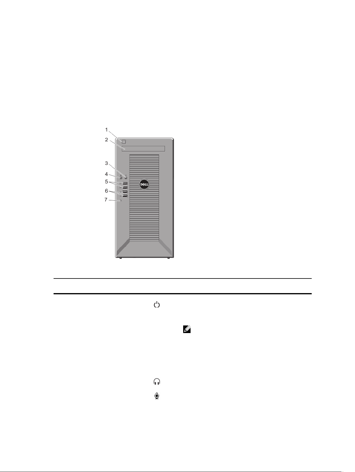
Figure 1. Front-Panel Features and Indicators
Item Indicator, Button, or
Connector
1 Power-on indicator, power
button
2 Optical drive (optional) One optional slim SATA DVD-ROM drive or DVD+/-RW
3 Headphone connector Allows you to connect a headphone to the system.
4 Microphone connector Allows you to connect a microphone to the system.
Icon Description
The power-on indicator lights when the system power is
on. The power button controls the power supply output to
the system.
NOTE: On ACPI-compliant operating systems, turning
off the system using the power button causes the
system to perform a graceful shutdown before power
to the system is turned off.
drive.
7
Item Indicator, Button, or
Connector
5 USB connectors (2) Allow you to connect USB devices to the system. The
6 USB connectors (2) Allow you to connect USB devices to the system. The
7 Hard drive indicator Indicates the hard drive activity.
Icon Description
ports are USB 3.0 compliant.
ports are USB 2.0 compliant.
Back-Panel Features And Indicators
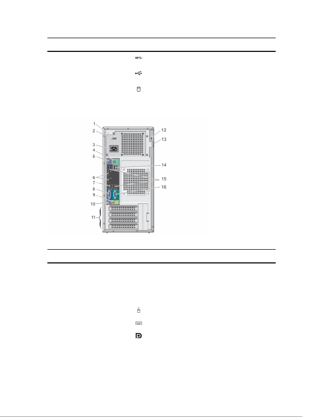
Figure 2. Back-Panel Features and Indicators
Item Indicator, Button, or
Connector
1 AC power supply status
indicator
2 Self-diagnostic button Indicates the health status of the non-redundant power
3 Power supply One 290 W non-redundant AC power supply.
4 PS/2 mouse connector Allows you to connect a PS/2 mouse to the system.
5 PS/2 keyboard connector Allows you to connect a PS/2 keyboard to the system.
6 Display ports (2) Allow you to connect other external display devices to the
8
Icon Description
Indicates power supply activity.
supply.
system.
Item Indicator, Button, or
Connector
7 USB connectors (2) Allow you to connect USB devices to the system. The
8 Video connector Allows you to connect a VGA display to the system.
9 Line-out connector Allows you to connect other output devices to the system.
Icon Description
ports are USB 3.0 compliant.
10 Line-in/microphone
connector
11 Expansion card slots (4) Allow you to connect up to three full-height PCIe
12 Security-cable slot Allows you to connect a cable lock to the system.
13 Padlock ring Locks the cover release latch.
14 Ethernet connector
15 USB connectors (4) Allow you to connect USB devices to the system. The
16 Serial connector Allows you to connect a serial device to the system.
Allows you to connect other external audio devices to the
system.
expansion cards and one full-height PCI expansion card.
One integrated 10/100/1000 Mbps NIC connector.
ports are USB 2.0 compliant.
NIC Indicator Codes
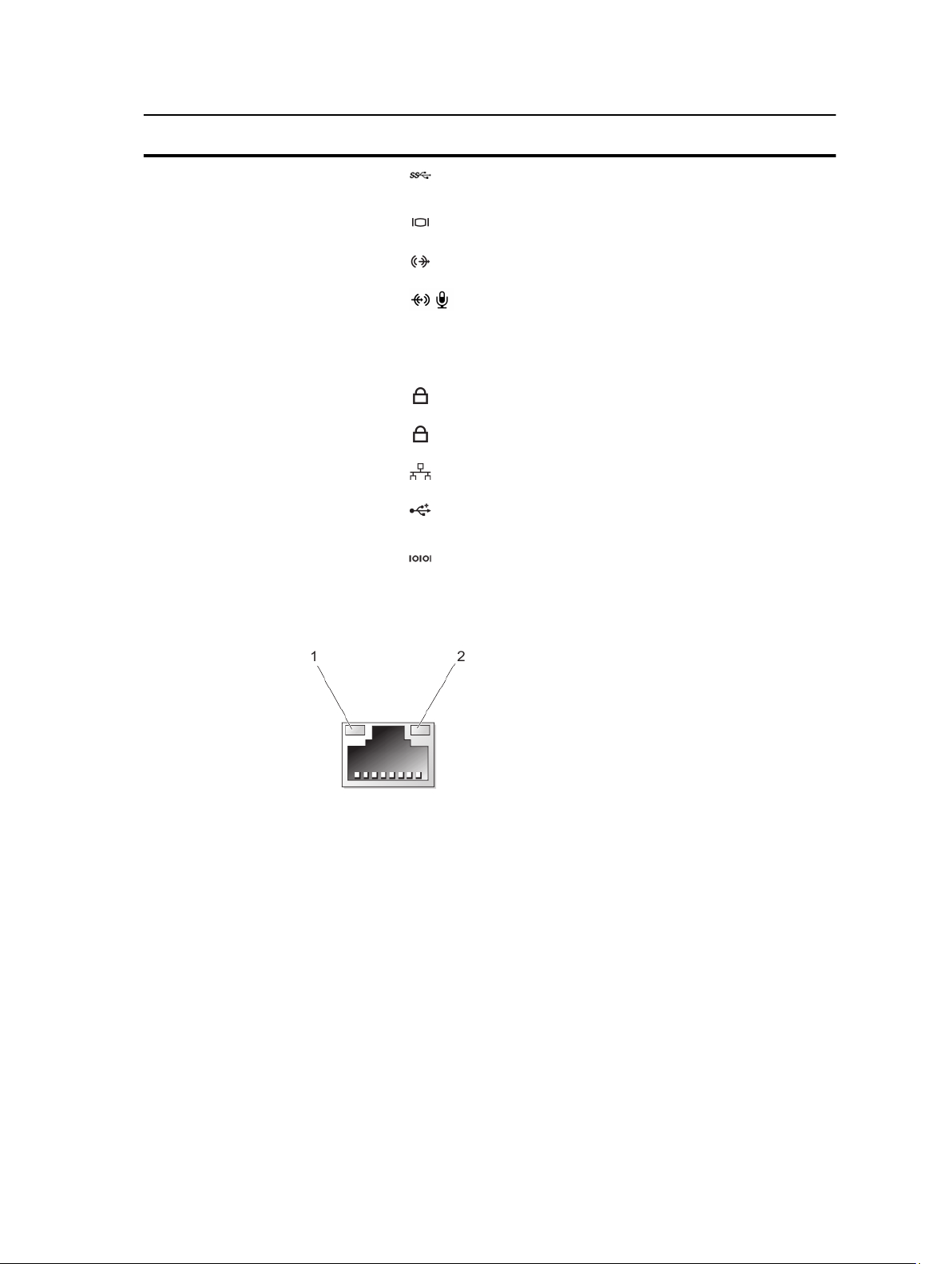
Figure 3. NIC Indicator Codes
1. link indicator
2. activity indicator
Indicator Indicator Code
Link integrity light on
integrated network
adapter
Green — a good 10 Mbps connection exists between the network and the system.
Green — a good 100 Mbps connection exists between the network and the system.
Orange — a good 1000 Mbps connection exists between the network and the system.
Off (no light) — the system is not detecting a physical connection to the network.
9
Indicator Indicator Code
Network activity light
on integrated
network adapter
Yellow light — A blinking yellow light indicates that network activity is present.
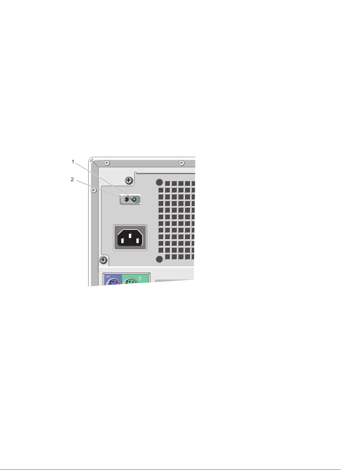
Power Indicator Codes For Power Supply
Press the self-diagnostic button to perform a quick health check on the non-redundant power supply of the system.
Diagnostic Indicator
Pattern
Not lit Power is not connected or power supply is faulty.
Green A valid power source is connected to the power supply and the power supply is operational.
Condition
Figure 4. Power Supply Status Indicator and Self-Diagnostic Button
1. AC power supply status indicator
2. self-diagnostic button
Complete The Operating System Setup
To install an operating system for the first time, see the installation and configuration documentation for your operating
system. Be sure that the operating system is installed before installing hardware or software not purchased with the
system.
Supported Operating Systems
The following operating systems are supported:
• Microsoft Windows Server 2012
10

• Red Hat Enterprise Linux 6.5 and later
NOTE: For latest information on supported operating systems, see dell.com/ossupport.
Other Information You May Need
WARNING: See the safety and regulatory information that shipped with your system. Warranty information may be
included within this document or as a separate document.
• The Owner’s Manual provides information about system features and describes how to troubleshoot the system and
install or replace system components. This document is available online at www.dell.com/poweredgemanuals.
• Any media that ships with your system that provides documentation and tools for configuring and managing your
system, including those pertaining to the operating system, system management software, system updates, and
system components that you purchased with your system.
• For latest information on supported operating systems, see dell.com/ossupport.
NOTE: Always check for updates on dell.com/support/manuals and read the updates first because they often
supersede information in other documents.
NOTE: When upgrading your system, it is recommended that you download and install the latest BIOS, driver, and
systems management firmware on your system from dell.com/support.
11

12

Using The System Setup And Boot Manager
System Setup enables you to manage your system hardware and specify BIOS-level options.
The following keystrokes provide access to system features during startup:
Keystroke Description
<F2> Enters the System Setup.
<F12> Enters the Boot Manager.
From the System Setup, you can:
• Change the NVRAM settings after you add or remove hardware
• View the system hardware configuration
• Enable or disable integrated devices
• Set performance and power management thresholds
• Manage system security
From the Boot Manager, you can:
• Verify the boot mode and the secure boot status
• Select a one-time boot device
• Perform hardware diagnostics
• Configure the Intel Management Engine BIOS Extension
• Update the BIOS
2
Choosing The System Boot Mode
System Setup enables you to specify the boot mode for installing your operating system:
• Legacy boot mode (the default) is the standard BIOS-level boot interface.
• Unified Extensible Firmware Interface (UEFI) boot mode is an enhanced 64-bit boot interface based on UEFI
specifications that overlays the system BIOS.
In System Setup, select boot mode in the Boot List Option field of the Boot Sequence screen. Once you specify the boot
mode, the system boots in the specified boot mode and then proceeds to install your operating system from that mode.
Thereafter, you must boot the system in the same boot mode (Legacy or UEFI) to access the installed operating system.
Trying to boot the operating system from the other boot mode will cause the system to halt at startup.
NOTE: Operating systems must be UEFI-compatible to be installed from the UEFI boot mode. DOS and 32-bit
operating systems do not support UEFI and can only be installed from the Legacy boot mode.
NOTE: For the latest information on supported operating systems, go to dell.com/ossupport.
13

Entering System Setup
1. Turn on or restart your system.
2. Press <F2>.
If your operating system begins to load before you press <F2>, allow the system to finish booting, and then restart
your system and try again.
Using The System Setup Navigation Keys
Key Description
Up arrow Moves to the previous field.
Down arrow Moves to the next field.
<Enter> Allows you to type in a value in the selected field (if applicable) or follow the link in the field.
Spacebar Expands or collapses a drop-down list, if applicable.
<Tab> Moves to the next focus area.
NOTE: For the standard graphics browser only.
<Esc> Moves to the previous page till you view the main screen. Pressing <Esc> in the main screen
exits the Boot Manager and proceeds with system boot.
NOTE: For most of the options, any changes that you make are recorded but do not take effect until you restart the
system.
Updating The BIOS
It is recommended to update your BIOS (system setup), on replacing the system board or if an update is available.
1. Restart the system.
2. Go to dell.com/support.
3. If you do not have your system's Service Tag or Express Service Code:
4. Enter the Service Tag or Express Service Code and click Submit.
NOTE: To locate the Service Tag, click Where is my Service Tag?
NOTE: If you cannot find your Service Tag, click Detect Service Tag. Proceed with the instructions on screen.
5. If you are unable to locate or find the Service Tag, click the product category of your system.
6. Choose the product type from the list.
7. Select your system model and the product support page of your system is displayed.
8. Click Drivers & Downloads.
9. On the Drivers and Downloads screen, under the Operating System drop-down list, select BIOS.
10. Identify the latest BIOS file and click Download File.
11. Select your preferred download method in the Please select your download method below window and click
Download File.
The File Download window is displayed.
12. Click Save to save the file on your system.
14

13. Click Run to install the updated BIOS settings on your system.
Follow the instructions on the screen.
Responding To Error Messages
If an error message is displayed while the system is booting, make a note of the message. For more information, see
System Messages.
NOTE: After installing a memory upgrade, it is normal for your system to display a message the first time you start
your system.
System Setup Options
NOTE: Depending on the system and its installed devices, the items listed in this section may or may not .
Table 1. General
Option Description
System Information Displays the following information:
• System Information — Displays BIOS Version, Service Tag, Asset Tag, Ownership
Tag, Ownership Date, Manufacture Date, and the Express Service Code.
• Memory Information — Displays Memory Installed, Memory Available, Memory
Speed, Memory Channels Mode, Memory Technology, DIMM 1 Size, DIMM 2
Size, DIMM 3 Size, and DIMM 4 Size.
• PCI Information — Displays SLOT1, SLOT2, SLOT3, and SLOT4.
• Processor Information — Displays Processor Type, Core Count, Processor ID,
Current Clock Speed, Maximum Clock Speed, Processor L2 Cache, Processor L3
Cache, HT Capable, and 64-Bit Technology.
• Device Information — Displays SATA-0, SATA-1, SATA-2, SATA-3, LOM MAC
Address, Audio Controller, and Video Controller.
Boot Sequence
Advanced Boot Options
Date/Time Allows you to set the date and time. Changes to the system date and time take effect
Boot Sequence — Allows you to specify the order in which the system attempts to
find an operating system. The options are:
• Diskette drive
• STXXXXXX / STXXXXXX
• USB storage device
• CD/DVD/CD-RW drive
• Onboard NIC
Boot List Option — Allows you to choose or change the boot mode for installing your
operating system. The options are:
• Legacy
• UEFI
NOTE: If you boot the system to the BIOS boot mode after installing an operating
system with UEFI boot mode, the system does not respond. You must boot to the
same boot mode in which you installed the operating system.
Enable Legacy Option ROMs — This option is enabled by default.
immediately.
15

Table 2. System Configuration
Option Description
Integrated NIC Allows you to enable or disable the integrated network card. You can set the
integrated NIC to:
• Disabled
• Enabled
• Enabled w/PXE (this option is enabled by default)
• Enable UEFI Network Stack
NOTE: Depending on the system and the devices installed, the items listed in this
section may or may not be displayed.
Serial Port Allows you to define the serial port settings. You can set the serial port to:
• Disabled
• COM1
• COM2
• COM3
• COM4
NOTE: The operating system may allocate resources even though the setting is
disabled.
SATA Operation Allows you to configure the operating mode of the integrated hard-drive controller.
• Disabled — The SATA controllers are hidden.
• ATA — SATA is configured for ATA mode.
• AHCI — SATA is configured for AHCI mode.
• RAID ON — SATA is configured to support RAID mode.
Drives Allows you to enable or disable the various on-board drives:
• SATA-0
• SATA-1
• SATA-2
• SATA-3
SMART Reporting This field controls if the hard drive errors for the integrated drives are reported during
system startup. This technology is part of the SMART (Self Monitoring Analysis and
Reporting Technology) specification.
• Enable SMART Reporting — This option is disabled by default.
USB Configuration This field configures the integrated USB controller. If Boot Support is enabled, the
system is allowed to boot any type of USB mass storage devices (HDD, memory key,
floppy).
If the USB port is enabled, the device attached to this port is enabled and available
for the operating system.
If the USB port is disabled, the operating system cannot see any device attached to
this port.
The options for USB configuration may differ based on the form factors:
• Enable Boot Support
16

Option Description
• Enable Front USB 2.0 Ports
• Enable USB 3.0 Ports
• Enable Rear–Left Dual USB 2.0 Ports
• Enable Rear–Right Dual USB 2.0 Ports (this option is enabled by default)
NOTE: USB keyboard and mouse always work in the BIOS setup irrespective of
these settings.
Audio Allows you to enable or disable the integrated audio controller.
• Enable Audio — This option is enabled by default.
Miscellaneous Devices Allows you to enable or disable various on-board devices.
• Enable PCI Slot — This option is enabled by default.
Table 3. Security
Option Description
Admin Password This field lets you set, change, or delete the administrator (admin) password
(sometimes called the setup password). The Admin Password enables several
security features.
1. Enter the old password.
2. Enter the new password.
3. Confirm the new password.
The password is not set by default.
System Password This field lets you set, change, or delete the system password (previously called the
primary password). The System Password enables several security features.
1. Enter the old password.
2. Enter the new password.
3. Confirm the new password.
The password is not set by default.
Internal HDD_0 Password This option lets you set, change, or delete the password on the system's internal hard
disk drive. The Internal HDD_0 Password enables several security features.
1. Enter the old password.
2. Enter the new password.
3. Confirm the new password.
The drive does not have a password set by default.
Strong Password
Enable strong password — This option is disabled by default.
Password Configuration This field controls the minimum and maximum number of characters allowed for the
admin and system passwords.
• Admin Password Min
• Admin Password Max
• System Password Min
17

Option Description
• System Password Max
Password Bypass Allows you to bypass the System Password and the internal HDD password prompts
during a system restart.
• Disabled — Always prompt for the system and internal HDD password when they
are set. This option is disabled by default.
• Reboot Bypass — Bypass the password prompts on restarts (warm boots).
NOTE: The system always prompts for the system and internal HDD passwords
when powered on from the off state (a cold boot). Also, the system always
prompts for passwords on any module bay HDDs that may be present.
Password Change Allows you to determine whether changes to the system and hard disk passwords are
permitted when an administrator password is set.
• Allow Non-Admin Password Changes — This option is enabled by default.
TPM Security This option lets you control whether the Trusted Platform Module (TPM) in the system
is enabled and visible to the operating system.
TPM Security — This option is disabled by default.
When the TPM Security option is enabled, it displays the following advanced options:
• TPM ACPI Support
• TPM PPI Deprovision Override
• Clear
• TPM PPI Provision Override
NOTE: Activation, deactivation, and clear options are not affected if you load the
setup program's default values. Changes to the TPM Security option take effect
immediately.
Computrace(R)
Chassis-Intrusion Allows you to enable or disable the chassis-intrusion alert.
Processor XD Support Allows you to enable or disable the execute disable mode of the processor.
This field lets you activate or disable the BIOS module interface of the optional
Computrace Service from Absolute Software.
• Deactivate — This option is disabled by default.
• Disable
• Activate
• Disable
• Enable
• On-Silent — This option is enabled by default.
Once a chassis intrusion has been detected, the system will add the chassis-intrusion
alert into the BIOS events at each cold/warm boot. The following option will then be
displayed:
• Clear Intrusion Warning — This option allows you to acknowledge and clear the
chassis-intrusion status.
18

Option Description
• Enable processor XD Support — This option is enabled by default.
OROM Keyboard Access Allows you to determine if you access the Option Read Only Memory (OROM)
configuration screens via hotkeys during boot. These settings prevent access to the
Intel RAID (CTRL+I) or Intel Management Engine BIOS Extension (CTRL+P/F12).
• Enable — User may enter OROM configuration screens via the hotkey.
• One-Time Enable — User can enter the OROM configuration screens via the
hotkeys during the next boot. After the boot, the setting will revert to disabled.
• Disable — User cannot enter the OROM configuration screens via the hotkey.
The OROM Keyboard Access option is set to Enable by default.
Admin Setup Lockout Allows you to enable or disable the option to enter setup when an admin password is
set.
• Enable Admin Setup Lockout — This option is not set by default.
Table 4. Secure Boot
Option Description
Secure Boot Enable Allows you to enable or disable Secure Boot feature.
• Disable
• Enable
NOTE: For Secure Boot to be enabled the system has to be in the UEFI boot mode
and the Enable Legacy Option ROMs needs to be turned off.
Expert Key Management Allows you to manipulate the security key databases only if the system is in Custom
Mode. The Enable Custom Mode option is disabled by default. The options are:
• PK
• KEK
• db
• dbx
If you enable the Custom Mode, the relevant options for PK, KEK, db, and dbx are
displayed. The options are:
• Save to File — Saves the key to a user-selected file.
• Replace from File — Replaces the current key with a key from a user-selected
file.
• Append from File — Adds a key to the current database from a user-selected file.
• Delete — Deletes the selected key.
• Reset All Keys — Resets to default setting.
• Delete All Keys — Deletes all the keys.
NOTE: If you disable the Custom Mode, all the changes will be erased and the
keys will restore to default settings.
19

Table 5. Performance
Option Description
Multi Core Support Specifies whether the processor will have one or all cores enabled. The performance
of some applications will improve with the additional cores.
• All — Enabled by default.
• 1
• 2
Intel SpeedStep Allows you to enable or disable the Intel SpeedStep mode of the processor. This
option is enabled by default.
C States Control Allows you to enable or disable the additional processor sleep states. This option is
enabled by default.
Limit CPUID Value This field limits the maximum value the processor standard CPUID function will
support.
• Enable CPUID Limit — This option is disabled by default.
NOTE: Some operating systems will not complete installation when the maximum
CPUID function is greater than three.
Intel TurboBoost Allows you to enable or disable Intel TurboBoost mode of the processor.
• Disabled — Does not allow the Intel TurboBoost driver to increase the
performance state of the processor above the standard performance.
• Enabled — Allows the Intel TurboBoost driver to increase the performance of the
processor or graphics processor.
Hyper-Thread Control Allows you to enable or disable the Hyper-Threading technology. This option is
enabled by default.
Table 6. Power Management
Option Description
AC Recovery Specifies how the system will respond when AC power is applied after an AC power
loss. You can set the AC Recovery to:
• Power Off
• Power On
• Last Power State
Auto On Time This option sets the time of the day when you would like the system to turn on
automatically. Time is kept in standard 12-hour format (hour:minutes:seconds). The
startup time can be changed by typing the values in the time and A.M./P.M. fields.
• Disabled — The system will not automatically power up.
• Every Day — The system will power up every day at the time you specified above.
• Weekdays — The system will power up Monday through Friday at the time you
specified above.
• Select Days — The system will power up on days selected above at the time you
specified above.
20

Option Description
NOTE: This feature does not work if you turn off your system using the switch on
a power strip or surge protector or if Auto Power is set to disabled.
Deep Sleep Control Allows you to define the controls when Deep Sleep is enabled.
• Disabled
• Enabled in S5 only
• Enabled in S4 and S5
This option is disabled by default.
Fan Control Override Controls the speed of the system fan. This option is disabled by default.
NOTE: When enabled, the fan runs at full speed.
USB Wake Support This option allows you to enable USB devices to wake the system from standby.
• Enable USB Wake Support — This option is disabled by default.
Wake on LAN This option allows the system to power up from the off state when triggered by a
special LAN signal. Wakeup from the Standby state is unaffected by this setting and
must be enabled in the operating system. This feature only works when the system is
connected to AC power supply. The options differ based on the form factor.
• Disabled — Does not allow the system to power on by special LAN signals when
it receives a wakeup signal from the LAN or wireless LAN.
• LAN Only — Allows the system to be powered on by special LAN signals.
• LAN with PXE Boot — Allows the system to be powered on by special LAN or PXE
bootsignals.
This option is disabled by default.
Block Sleep This option lets you block entering to sleep (S3 state) in operating system
environment.
• Block Sleep (S3 state) — This option is disabled by default.
Table 7. POST Behavior
Option Description
Numlock LED Specifies if the NumLock function can be enabled when the system boots. This option
is enabled by default.
Keyboard Errors Specifies whether keyboard related errors are reported when it boots. This option is
enabled by default.
MEBx Hotkeys Specifies whether the MEBx Hotkey function should be enabled when the system
boots.
• Enable MEBx Hotkey — This option is enabled by default.
21

Table 8. Virtualization Support
Option Description
Virtualization This option specifies whether a Virtual Machine Monitor (VMM) can utilize the
additional hardware capabilities provided by Intel Virtualization technology.
• Enable Intel Virtualization Technology — This option is enabled by default.
VT for Direct I/O Enables or disables the VMM from utilizing the additional hardware capabilities
provided by Intel Virtualization technology for direct I/O.
• Enable Intel Virtualization Technology for Direct I/O — This option is enabled by
default.
NOTE: This is supported only on Intel Xeon processor-based systems.
Trusted Execution This option specifies whether a Measured Virtual Machine Monitor (MVMM) can
utilize the additional hardware capabilities provided by Intel Trusted Execution
technology. The TPM virtualization technology and virtualization technology for direct
I/O must be enabled to use this feature.
• Trusted Execution — This option is disabled by default.
NOTE: This is supported only on Intel Xeon processor-based systems.
Table 9. Maintenance
Option Description
Service Tag Displays the service tag of your system.
Asset Tag Allows you to create a system asset tag if an asset tag is not already set. This option
is not set by default.
SERR Messages Controls the SERR message mechanism. This option is not set by default. Some
graphics cards require that the SERR message mechanism be disabled.
Table 10. System Logs
Option Description
BIOS events Displays the system event log and allows you to clear the log.
• Clear Log
Boot Manager Screen
Option Description
LEGACY/UEFI BOOT Allows you to select a one-time boot device from bootable devices list.
OTHER OPTIONS
BIOS Setup Enters System Setup.
BIOS Flash Update Allows you to update the BIOS from the USB drive with the released BIOS file. This
option is for advanced users.
22

Option Description
1. Download the BIOS file from dell.com/support. For more information, see
Updating The BIOS.
2. Save the BIOS file on a USB drive (FAT32).
3. Press <F12> while powering up the system to select the BIOS Flash Update.
4. Insert the USB drive into the USB port.
5. Select the BIOS file and proceed to the update.
Diagnostics Allows you to enter the System Diagnostics. For more information, see Using
System Diagnostics.
Intel Management
Engine BIOS Extension
Change Boot Mode
Settings
Allows you to configure Intel MEBX.
Allows you to change the boot mode (Legacy/UEFI).
NOTE: If you boot the system to the BIOS boot mode after installing an
operating system from the UEFI Boot Manager, the system hangs. The reverse
is also true. You must boot to the same boot mode in which you installed the
operating system.
Using The Boot Manager Navigation Keys
Key Description
Up arrow Moves to the previous field.
Down arrow Moves to the next field.
<Enter> Allows you to type in a value in the selected field (if applicable) or follow the link in the field.
<Esc> Moves to the previous page till you view the main screen. Pressing <Esc> in the main screen
exits the Boot Manager and proceeds with system boot.
NOTE: For most of the options, any changes that you make are recorded but do not take effect until you restart the
system.
System And Admin Password Features
You can create a system password and a admin password to secure your system. To create a system and admin
password, the password jumper must be set to enabled. For more information on the password jumper settings, see
System Board Jumper Settings.
System password This is the password that you must enter before you boot your system.
Admin password This is the password that you must enter to access and make changes to the BIOS or UEFI
settings of your system.
CAUTION: The password features provide a basic level of security for the data on your system.
CAUTION: Anyone can access the data stored on your system if the system is running and unattended.
NOTE: Your system is shipped with the system and admin password feature disabled.
23

Assigning A System Password And Admin Password
You can assign a new System Password and/or Admin Password or change an existing System Password and/or Admin
Password only when Password Status is Unlocked. If the Password Status is Locked, you cannot change the System
Password.
NOTE: If the password jumper is disabled, the existing System Password and admin Password is deleted. You do
not need to provide the system password to log on to the system.
To enter the System Setup, press <F2> immediately after a power-on or reboot.
1. In the System BIOS or System Setup screen, select Security and press <Enter>.
The Security screen is displayed.
2. Select System Password , enter your system password, and press <Enter> or <Tab>.
Use the following guidelines to assign the system password:
– A password can have up to 32 characters.
– The password can contain the numbers 0 through 9.
– Only the following special characters are allowed: space, (”), (+), (,), (-), (.), (/), (;), ([), (\), (]), (`).
3. Re-enter the system password that you entered earlier and click OK.
4. Select Admin Password, enter your system password and press <Enter> or <Tab>.
A message prompts you to retype the admin password.
5. Re-enter the admin password that you entered earlier and click OK.
6. Press <Esc> and a message prompts you to save the changes.
7. Press <Y> to save the changes and exit from the System Setup.
The system reboots.
Deleting Or Changing An Existing System And Admin Password
Ensure that the Password Status is Unlocked (in the System Setup) before attempting to delete or change the existing
System and/or admin password. You cannot delete or change an existing System or admin password, if the Password
Status is Locked.
To enter System Setup, press <F2> immediately after a power-on or reboot.
1. In the System BIOS or System Setup screen, select Security and press <Enter>.
The Security screen is displayed.
2. Select System Password, alter or delete the existing system password and press <Enter> or <Tab>.
3. Select Admin Password, alter or delete the existing admin password and press <Enter> or <Tab>.
NOTE: If you change the system and/or admin password, re-enter the new password when promoted. If you
delete the system and/or admin password, confirm the deletion when promoted.
4. Press <Esc> and a message prompts you to save the changes.
5. Press <Y> to save the changes and exit from the System Setup.
The system reboots.
Intel Active Management Technology
Intel Active Management Technology (AMT) enables you to remotely manage, diagnose, and repair the managed server.
24

NOTE: Intel AMT is supported only on Intel Xeon processor-based systems.
It provides the following features:
• Allows you to discover devices even while the system is powered off.
• With out-of-band management capabilities, you can remotely remediate and recover systems after OS failures.
• Blocks incoming threats and infected clients before they affect the network.
• Provides remote hardware and software asset tracking.
For more information on Intel AMT, see www.intel.com/amt.
25

26
 Loading...