

Page 1

Dell™ PowerEdge™ T100 Systems
Hardware Owner’s Manual
www.dell.com | support.dell.com
Page 2

Notes, Notices, and Cautions
NOTE: A NOTE indicates important information that helps you make better use of
your computer.
NOTICE: A NOTICE indicates either potential damage to hardware or loss of data
and tells you how to avoid the problem.
CAUTION: A CAUTION indicates a potential for property damage, personal injury,
or death.
____________________
Information in this document is subject to change without notice.
© 2008-2009 Dell Inc. All rights reserved.
Reproduction in any manner whatsoever without the written permission of Dell Inc. is strictly
forbidden.
Trademarks used in this text: Dell, the DELL logo, and Pow er Edg e are trademarks of Dell Inc.; Intel
is a registered trademark of Intel Corporation in the U.S. and other countries; Microsoft, MS-DOS,
Windows, and Windows Server are either trademarks or registered trademarks of Microsoft Corporation
in the United States and/or other countries; UNIX is a registered trademark of The Open Group in the
United States and other countries.
Other trademarks and trade names may be used in this document to refer to either the entities claiming
the marks and names or their products. Dell Inc. disclaims any proprietary interest in trademarks and
trade names other than its own.
June 2009 Rev. A01
Page 3

Contents
1 About Your System . . . . . . . . . . . . . . . . . . . 9
Other Information You May Need . . . . . . . . . . . . . 9
Accessing System Features During Startup
Front-Panel Features and Indicators
Back-Panel Features and Indicators
Connecting External Devices
NIC Indicator Codes
Power Supply Indicators
Diagnostic Lights
System Messages
Warning Messages
. . . . . . . . . . . . . . . . . . . . 16
. . . . . . . . . . . . . . . . . . . . 18
. . . . . . . . . . . . . . . . . . . 27
Diagnostics Messages
Alert Messages
. . . . . . . . . . . . . . . . . . . . . 27
. . . . . . . . . . . . . . . . . 27
. . . . . . . . . . . . 14
. . . . . . . . . . . . . . . . 14
. . . . . . . . . . . . . . 15
. . . . . . . 10
. . . . . . . . . . 11
. . . . . . . . . . 13
2 Using the System Setup Program . . . . . . 29
Entering the System Setup Program . . . . . . . . . . . 29
Responding to Error Messages
Using the System Setup Program
. . . . . . . . . . . 29
. . . . . . . . . 30
System Setup Options
Main Screen
. . . . . . . . . . . . . . . . . . . . 30
. . . . . . . . . . . . . . . . . . 30
Contents 3
Page 4

Memory Information Screen . . . . . . . . . . . . 33
CPU Information Screen
SATA Configuration Screen
Integrated Devices Screen
Console Redirection Screen
System Security Screen
Exit Screen
. . . . . . . . . . . . . . . . . . . . . 38
. . . . . . . . . . . . . . 33
. . . . . . . . . . . . . 34
. . . . . . . . . . . . . 35
. . . . . . . . . . . . 36
. . . . . . . . . . . . . . 36
System and Setup Password Features
Using the System Password
Using the Setup Password
Disabling a Forgotten Password
. . . . . . . . . . 38
. . . . . . . . . . . . 39
. . . . . . . . . . . . . 42
. . . . . . . . . . . . . 43
3 Installing System Components . . . . . . . 45
Recommended Tools . . . . . . . . . . . . . . . . . . . 45
Inside the System
Opening the System
Closing the System
Front Drive Bezel
Removing the Front Drive Bezel
Replacing the Front Drive Bezel
Removing an Insert on the Front Drive Bezel
Replacing an Insert on the Front Drive Bezel
Removing and Inserting Blank Drive Inserts
. . . . . . . . . . . . . . . . . . . . . 46
. . . . . . . . . . . . . . . . . . . 47
. . . . . . . . . . . . . . . . . . . . 47
. . . . . . . . . . . . . . . . . . . . . 48
. . . . . . . . . . 49
. . . . . . . . . . 49
. . . . 50
. . . . 50
. . . . . . 51
4 Contents
Diskette Drive
. . . . . . . . . . . . . . . . . . . . . . 52
Removing the Diskette Drive
Installing a Diskette Drive
Optical and Tape Drives
. . . . . . . . . . . . 52
. . . . . . . . . . . . . . 54
. . . . . . . . . . . . . . . . . 57
Page 5

Removing an Optical or Tape Drive. . . . . . . . . 57
Installing an Optical or Tape Drive
. . . . . . . . . 60
Hard Drives
Expansion Cards
Memory
. . . . . . . . . . . . . . . . . . . . . . . . 64
Hard Drive Installation Guidelines
Removing a Hard Drive
Installing a Hard Drive
. . . . . . . . . . . . . . . . . . . . . 70
. . . . . . . . . . . . . . . 64
. . . . . . . . . . . . . . . 66
Removing an Expansion Card
Installing an Expansion Card
SAS Controller Expansion Card
. . . . . . . . . . . . . . . . . . . . . . . . . 76
Memory Module Upgrade Kits
. . . . . . . . . 64
. . . . . . . . . . . 70
. . . . . . . . . . . . 73
. . . . . . . . . . 74
. . . . . . . . . . . 76
Memory Module Installation Guidelines
Addressing Memory With 8-GB Configurations
(Microsoft
Removing a Memory Module
Installing a Memory Module
Microprocessor
Removing the Processor
Replacing the Processor
Cooling Fans
Removing the Cooling Fans
Replacing the Cooling Fans
®
Windows® Operating System Only) . 77
. . . . . . . . . . . . 78
. . . . . . . . . . . . 78
. . . . . . . . . . . . . . . . . . . . . 80
. . . . . . . . . . . . . . 81
. . . . . . . . . . . . . . 83
. . . . . . . . . . . . . . . . . . . . . . . 84
. . . . . . . . . . . . . 84
. . . . . . . . . . . . . 87
. . . . . . 76
System Battery
. . . . . . . . . . . . . . . . . . . . . . 89
Removing the System Battery
Installing the System Battery
Power Supply
. . . . . . . . . . . . . . . . . . . . . . 92
Removing the Power Supply
Installing the Power Supply
. . . . . . . . . . . 90
. . . . . . . . . . . . 91
. . . . . . . . . . . . 92
. . . . . . . . . . . . 94
Contents 5
Page 6

Chassis Intrusion Switch . . . . . . . . . . . . . . . . 94
Removing the Chassis Intrusion Switch
Installing the Chassis Intrusion Switch
Bezel
. . . . . . . . . . . . . . . . . . . . . . . . . . . 96
Removing the Bezel
Replacing the Bezel
. . . . . . . . . . . . . . . . . 96
. . . . . . . . . . . . . . . . . 97
. . . . . . 94
. . . . . . . 95
I/O Panel Assembly
Removing the I/O Panel Assembly
Replacing the I/O Panel Assembly
System Board
Removing the System Board
Installing the System Board
. . . . . . . . . . . . . . . . . . . 98
. . . . . . . . . 98
. . . . . . . . . 99
. . . . . . . . . . . . . . . . . . . . . . 102
. . . . . . . . . . . 102
. . . . . . . . . . . . 103
4 Troubleshooting Your System . . . . . . . . 105
Safety First—For You and Your System . . . . . . . . 105
Start-Up Routine
Checking the Equipment
Troubleshooting External Connections
Troubleshooting the Video Subsystem
Troubleshooting the Keyboard or Mouse
Troubleshooting Serial I/O Problems
Troubleshooting a Serial I/O Device
Troubleshooting a USB Device
. . . . . . . . . . . . . . . . . . . . 105
. . . . . . . . . . . . . . . . 106
. . . . . . 106
. . . . . . 106
. . . . . . . 107
. . . . . . . . . 109
. . . . . . . 109
. . . . . . . . . . 110
6 Contents
Troubleshooting a NIC
. . . . . . . . . . . . . . . . . 112
Troubleshooting a Wet System. . . . . . . . . . . . . 113
Troubleshooting a Damaged System
. . . . . . . . . . 114
Page 7

Troubleshooting the System Battery. . . . . . . . . . . 114
Troubleshooting Power Supply
Troubleshooting System Cooling Problems
Troubleshooting a Fan
Troubleshooting System Memory
Troubleshooting a Diskette Drive
Troubleshooting an Optical Drive
Troubleshooting an External SCSI Tape Drive
Troubleshooting a Hard Drive
Troubleshooting a SAS or SAS RAID Controller
Troubleshooting Expansion Cards
Troubleshooting the Microprocessor
. . . . . . . . . . . . . 115
. . . . . . . 116
. . . . . . . . . . . . . . . 117
. . . . . . . . . . . . 118
. . . . . . . . . . . . 120
. . . . . . . . . . . . 122
. . . . . 123
. . . . . . . . . . . . . . 124
. . . . 125
. . . . . . . . . . . . 127
. . . . . . . . . . 129
5 Running the System Diagnostics . . . . . . 131
Using Dell PowerEdge Diagnostics . . . . . . . . . . . 131
System Diagnostics Features
. . . . . . . . . . . . . . 131
When to Use the System Diagnostics
Running the System Diagnostics
. . . . . . . . . . . . 132
System Diagnostics Testing Options
Using the Custom Test Options
. . . . . . . . . . . . . 133
Selecting Devices for Testing
Selecting Diagnostics Options
Viewing Information and Results
. . . . . . . . . . 132
. . . . . . . . . . 132
. . . . . . . . . . . 133
. . . . . . . . . . . 133
. . . . . . . . . . 134
Contents 7
Page 8

6 Jumpers and Connectors. . . . . . . . . . . . 135
System Board Jumpers. . . . . . . . . . . . . . . . . 135
System Board Connectors
Disabling a Forgotten Password
. . . . . . . . . . . . . . . 137
. . . . . . . . . . . . 139
7 Getting Help . . . . . . . . . . . . . . . . . . . . . . 141
Contacting Dell. . . . . . . . . . . . . . . . . . . . . 141
Glossary . . . . . . . . . . . . . . . . . . . . . . . . . . . . 143
Index
. . . . . . . . . . . . . . . . . . . . . . . . . . . . . . 155
8 Contents
Page 9

About Your System
This section describes the physical, firmware, and software interface features
that provide and ensure the essential functioning of your system. The
physical connectors on your system’s front and back panels provide
convenient connectivity and system expansion capability. The system
firmware, applications, and operating systems monitor the system and
component status and alert you when a problem arises. System conditions
can be reported by any of the following:
• Front or back panel indicators
• System messages
• Warning messages
• Diagnostics messages
• Alert messages
This section describes each type of message, lists the possible causes, and
provides steps to resolve any problems indicated by a message. The system
indicators and features are illustrated in this section.
Other Information You May Need
NOTE: Important safety and regulatory information is provided in another
document. Warranty information may be included within this document or as a
separate document.
• The
• CDs or DVDs included with your system provide documentation and tools
• Systems management software documentation describes the features,
• Operating system documentation describes how to install (if necessary),
• Documentation for any components you purchased separately provides
Getting Started Guide
up your system, and technical specifications.
for configuring and managing your system.
requirements, installation, and basic operation of the software.
configure, and use the operating system software.
information to configure and install these options.
provides an overview of system features, setting
About Your System 9
Page 10

• Updates are sometimes included with the system to describe changes to
the system, software, and/or documentation.
NOTE: Always check for updates on support.dell.com and read the updates
first because they often supersede information in other documents.
• Release notes or readme files may be included to provide last-minute
updates to the system or documentation or advanced technical reference
material intended for experienced users or technicians.
Accessing System Features During Startup
Table 1-1 describes keystrokes that may be entered during startup to access
system features. If your operating system begins to load before you enter the
keystroke, allow the system to finish booting, and then restart your system
and try again.
Table 1-1. Keystrokes for Accessing System Features
Keystroke Description
<F2> Enters the System Setup program. See "Using the System Setup
Program" on page 29.
<F10> Opens the utility partition, allowing you to run the system
diagnostics. See "Running the System Diagnostics" on page 132.
<F11> Enters the boot menu selection screen, allowing you to choose a boot
device.
<F12> Initiates PXE boot.
<Ctrl+C> Option is displayed for some SAS controller expansion cards. Enters
the SAS Configuration Utility, which includes RAID configuration
options. See your SAS adapter User’s Guide for more information.
<Ctrl+S> Option is displayed only if you have PXE support enabled through
the System Setup Program (see Table 2-1). This keystroke allows you
to configure NIC settings for PXE boot. For more information, see
the documentation for your integrated NIC.
10 About Your System
Page 11
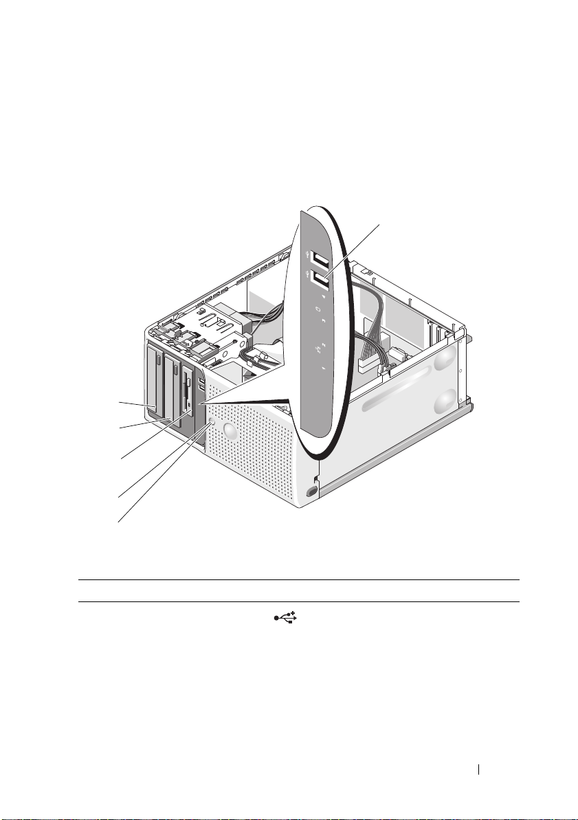
Front-Panel Features and Indicators
1
2
3
5
6
4
Figure 1-1 shows the controls, indicators, and connectors located on the
system's front panel. Table 1-2 provides component descriptions.
Figure 1-1. Front-Panel Features and Indicators
Table 1-2. Front-Panel Components
Item Component Icon Description
1 USB connectors (2) Connects USB 2.0-compliant
devices to the system.
About Your System 11
Page 12
Table 1-2. Front-Panel Components (continued)
Item Component Icon Description
2 power button The power button controls the DC
power supply output to the system.
NOTE: If you turn off the system using
the power button and the system is
running an ACPI-compliant operating
system, the system performs a
graceful shutdown before the power
is turned off. If the system is not
running an ACPI-compliant operating
system, the power is turned off
immediately after the power button is
pressed.
3 power light No light — The system is off.
Steady green — The system is
powered on.
Blinking green — The system is in a
low power state.
Steady amber — A BIOS failure
occurred before Power-On Self Test
(POST). See "Diagnostic Lights" on
page 16.
Blinking amber — There is a
problem with the power supply.
4 flex bay
5 lower 5.25-inch drive
bay
6 upper 5.25-inch drive
bay
Holds an optional diskette drive.
Holds an optional optical or tape
backup unit drive.
Holds an optical drive.
12 About Your System
Page 13
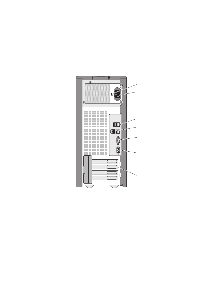
Back-Panel Features and Indicators
1
5
7
4
3
2
6
Figure 1-2 shows the controls, indicators, and connectors located on the
system's back panel.
Figure 1-2. Back-Panel Features and Indicators
1 voltage selection switch 2 power connector
3 USB connectors (5) 4 NIC connector
5 video connector 6 serial connector
7 I/O expansion-card slots (4)
About Your System 13
Page 14
Connecting External Devices
1
2
When connecting external devices to your system, follow these guidelines:
• Most devices must be connected to a specific connector and device drivers
must be installed before the device operates properly. (Device drivers are
normally included with your operating system software or with the device
itself.) See the documentation that accompanied the device for specific
installation and configuration instructions.
• Always attach an external device while your system and the device are
turned off. Next, turn on any external devices before turning on the system
(unless the documentation for the device specifies otherwise).
See "Using the System Setup Program" on page 29 for information about
enabling, disabling, and configuring I/O ports and connectors.
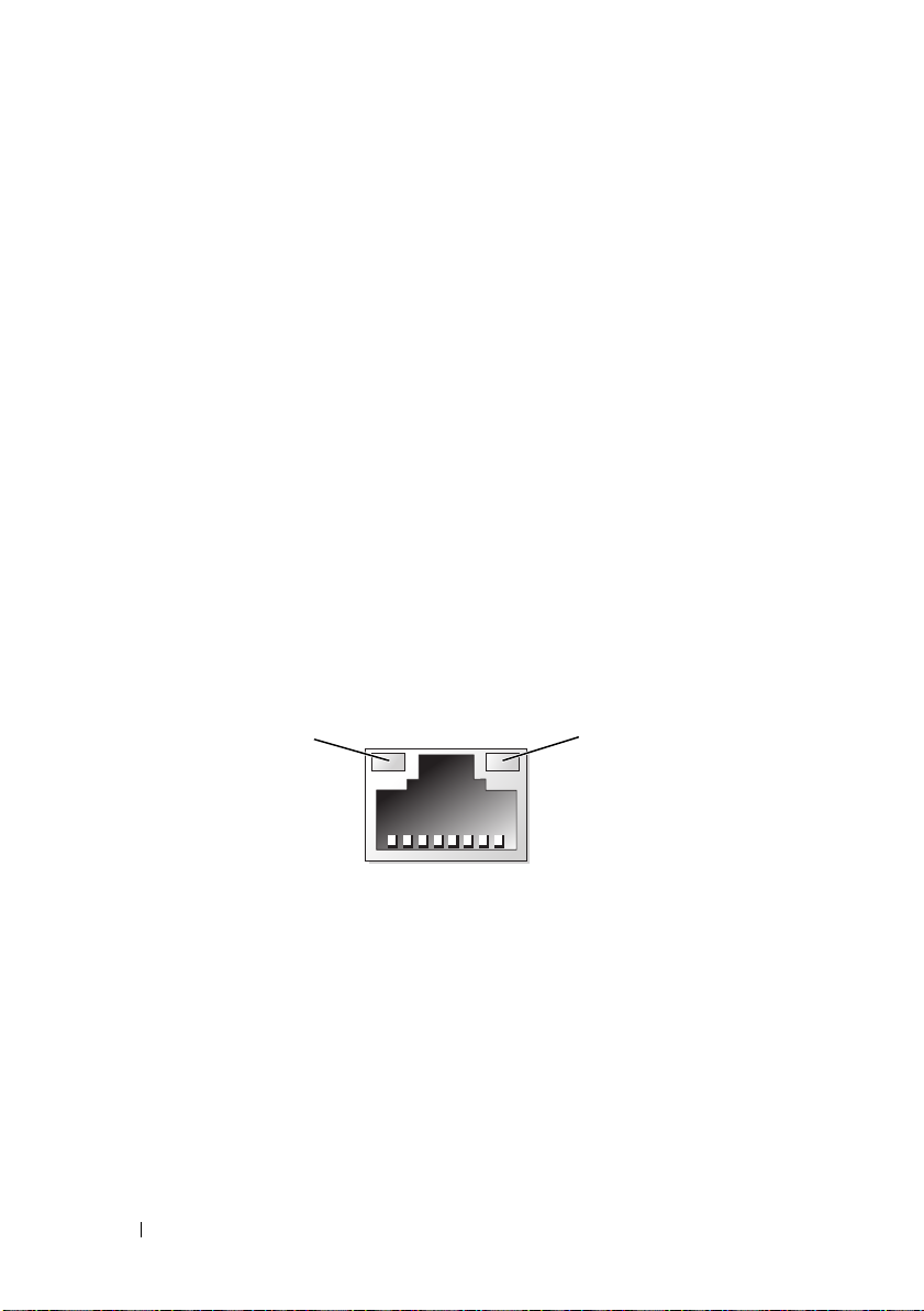
NIC Indicator Codes
The NIC on the back panel has an indicator that provides information on
network activity and link status. See Figure 1-3. Table 1-3 lists the NIC
indicator codes.
Figure 1-3. NIC Indicators
1 link indicator 2 activity indicator
14 About Your System
Page 15

Table 1-3. NIC Indicator Codes
Indicator Type Indicator Code Description
Activity Off When off at the same time that the link indicator
is off, the NIC is not connected to the network or
the NIC is disabled in the System Setup
program. See "Using the System Setup Program"
on page 29.
Blinking Indicates that network data is being sent or
received.
Link Off When off at the same time that the activity
indicator is off, the NIC is not connected to the
network or the NIC is disabled in the System
Setup program. See "Using the System Setup
Program" on page 29.
Yellow 1000-Mbps connection
Orange 100-Mbps connection
Green 10-Mbps connection
Power Supply Indicators
The voltage selection switch on the back panel of the system allows you to
select one of two primary voltage inputs. Ensure that the switch is set to the
proper voltage according to Table 1-4.
Table 1-4. Voltage Selection Switch
If your power source is: The voltage selection switch should be set to:
110 V
220 V
115
230
For information on system power requirements, see "Technical Specifications"
in your Getting Started Guide.
About Your System 15
Page 16
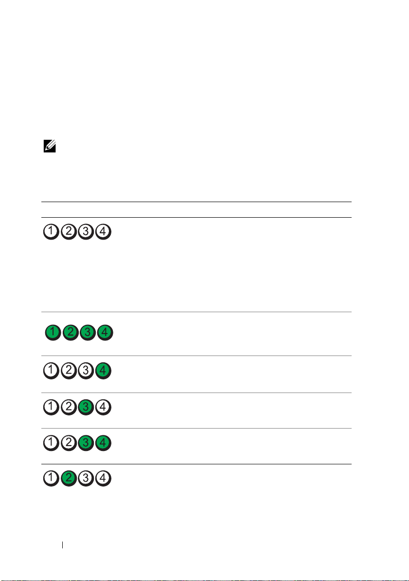
Diagnostic Lights
The four diagnostic indicator lights on the system front panel display error
codes during system startup. Table 1-5 lists the causes and possible corrective
actions associated with these codes. A highlighted circle indicates the light is
on; a non-highlighted circle indicates the light is off.
NOTE: If the power LEDs blink amber, there is a problem with the power supply. If
the power LED shows a solid amber, a BIOS failure occurred before Power-On Self
Test (POST).
Table 1-5. Diagnostic Indicator Codes
Code Causes Corrective Action
The computer is in a
normal off condition or a
possible pre-BIOS failure
has occurred.
The diagnostic lights are
not lit after the system
successfully boots to the
operating system.
The system is in a normal
operating condition after
POST.
Plug the computer into a working
electrical outlet and press the
power button.
Information only.
BIOS checksum failure
detected; system is in
recovery mode.
Possible processor failure. See "Troubleshooting the
Memory failure. See "Troubleshooting System
Possible expansion card
failure.
16 About Your System
See "Getting Help" on page 141.
Microprocessor" on page 129.
Memory" on page 118.
See "Troubleshooting Expansion
Cards" on page 127.
Page 17
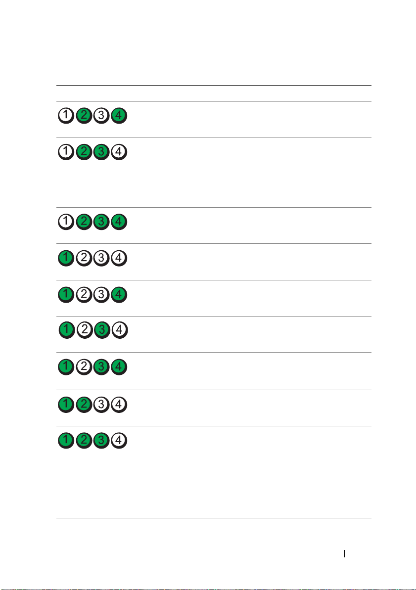
Table 1-5. Diagnostic Indicator Codes
Code Causes Corrective Action
Possible video failure. See "Getting Help" on page 141.
Diskette drive or hard
drive failure.
Possible USB failure. See "Troubleshooting a USB
No memory modules
detected.
System board failure. See "Getting Help" on page 141.
Memory configuration
error.
Possible system board
resource and/or system
board hardware failure.
Possible system resource
configuration error.
Ensure that the diskette drive and
hard drive are properly connected.
See "Hard Drives" on page 64 or
"Diskette Drive" on page 52 for
information on the drives
installed in your system.
Device" on page 110.
See "Troubleshooting System
Memory" on page 118.
See "Troubleshooting System
Memory" on page 118.
See "Getting Help" on page 141.
See "Getting Help" on page 141.
Other failure. Ensure that the diskette drive,
optical drive, and hard drives are
properly connected. See
"Troubleshooting Your System" on
page 105 for the appropriate drive
installed in your system. If the
problem persists, see "Getting
Help" on page 141.
About Your System 17
Page 18
System Messages
System messages appear on the screen to notify you of a possible problem
with the system. Table 1-6 lists the system messages that can occur and the
probable cause and corrective action for each message.
NOTE: If you receive a system message that is not listed in Table 1-6, check the
documentation for the application that is running when the message appears or the
operating system's documentation for an explanation of the message and
recommended action.
CAUTION: Many repairs may only be done by a certified service technician. You
should only perform troubleshooting and simple repairs as authorized in your
product documentation, or as directed by the online or telephone service and
support team. Damage due to servicing that is not authorized by Dell is not covered
by your warranty. Read and follow the safety instructions that came with the
product.
Table 1-6. System Messages
Message Causes Corrective Actions
Attempting to
update Remote
Configuration.
Please wait....
BIOS Update Attempt
Failed!
Caution! NVRAM_CLR
jumper is installed
on system board.
Remote Configuration is in
progress.
Remote BIOS update
attempt failed.
NVRAM_CLR jumper is
installed.
Wait until the process is
complete.
Retry the BIOS update. If
the problem persists, see
"Getting Help" on
page 141.
Check the System Setup
configuration settings. See
"Using the System Setup
Program
Remove the NVRAM_CLR
jumper. See Figure 6-1 for
jumper locations.
" on page 29.
18 About Your System
Page 19

Table 1-6. System Messages (continued)
Message Causes Corrective Actions
Data error The diskette drive or hard
drive cannot read the data.
Decreasing
available memory
Diskette read
failure
Diskette subsystem
reset failed
Drive not ready Diskette missing or
One or more memory
modules might be
improperly seated or faulty.
Faulty or improperly
inserted diskette.
Faulty diskette drive or
optical drive controller.
improperly inserted in
diskette drive.
For the operating system,
run the appropriate utility
to check the file structure
of the diskette drive or hard
drive.
See your operating system
documentation for
information on running
these utilities.
Reinstall the memory
modules and, if necessary,
replace them. See
"Memory" on page 76.
See "Troubleshooting
System Memory" on
page 118.
Replace the diskette.
Ensure that the diskette
drive and optical drive
cables are properly
connected. See
"Troubleshooting a USB
Device" on page 110 and
"Troubleshooting an
Optical Drive" on page 122.
If the problem persists, see
"Getting Help" on
page 141.
Reinsert or replace the
diskette.
About Your System 19
Page 20

Table 1-6. System Messages (continued)
Message Causes Corrective Actions
Error: Incorrect
memory
configuration.
Ensure memory in
slots DIMM1_A and
DIMM1_B, DIMM2_A
and DIMM2_B match
identically in
size, speed and
rank.
Error 8602:
Auxiliary device
failure. Verify
that mouse and
keyboard are
securely attached
to correct
connectors.
Gate A20 failure Faulty keyboard controller
General failure The operating system is
Keyboard controller
failure
Keyboard data line
failure
Keyboard failure
Keyboard stuck key
failure
The installed memory
modules are not matched
pairs.
Loose or improperly
connected mouse or
keyboard cable; faulty
mouse or keyboard.
(faulty system board).
unable to carry out the
command.
Faulty keyboard controller
(faulty system board).
Loose or improperly
connected keyboard cable;
faulty keyboard; faulty
keyboard controller.
See "Memory Module
Installation Guidelines" on
page 76.
Replace the mouse. If the
problem persists, replace
the keyboard.
See "Getting Help" on
page 141.
This message is usually
followed by specific
information. Take the
appropriate action to
resolve the problem.
See "Getting Help" on
page 141.
Ensure that the keyboard is
properly connected. If the
problem persists, replace
the keyboard. If the
problem persists, see
"Getting Help" on
page 141.
20 About Your System
Page 21

Table 1-6. System Messages (continued)
Message Causes Corrective Actions
Keyboard fuse has
failed.
Manufacturing mode
detected
Memory address line
failure at
value
read
expecting
Memory double word
logic failure at
address
expecting
Memory odd/even
logic failure at
start address
address
value
, read
value
value
to
Keyboard fuse has failed. Replace the keyboard.
Faulty system board. If the problem persists, the
system board is faulty. See
"Getting Help" on
page 141.
System is incorrectly
configured.
Faulty or improperly
,
installed memory modules,
or faulty system board.
Ensure that all memory
modules are properly
installed. See
"Troubleshooting System
Memory" on page 118. If
the problem persists, see
"Getting Help" on
page 141.
end address
Memory write/read
failure at
value
read
expecting
Memory tests
terminated by
keystroke
address
value
,
The spacebar was pressed
during POST to terminate
the memory test.
Information only.
About Your System 21
Page 22

Table 1-6. System Messages (continued)
Message Causes Corrective Actions
No boot device
available
No boot sector on
hard-disk drive
No timer tick
interrupt
The system cannot find the
diskette or hard drive.
The system configuration
information in the System
Setup program might be
incorrect.
A chip on the system board
might be malfunctioning.
If the diskette drive is your
boot device, ensure that a
bootable disk is in the drive.
If the hard drive is your
boot device, ensure that the
hard drive is installed,
properly seated, and
partitioned as a boot
device.
Enter the System Setup
program and verify the boot
sequence information. See
"System Setup Options" on
page 30.
Enter the System Setup
program and verify the
system configuration
information for the hard
drive. See "System Setup
Options" on page 30.
If the message continues to
appear after verifying the
information in the System
Setup program, the
operating system might
have been corrupted.
Reinstall the operating
system. See your operating
system documentation for
reinstallation information.
Run the system diagnostics.
See "Running the System
Diagnostics" on page 131.
22 About Your System
Page 23

Table 1-6. System Messages (continued)
Message Causes Corrective Actions
Not a boot diskette The operating system is
trying to boot from a
diskette that does not have
a bootable operating system
installed on it.
Option ROM Checksum
Error
PCIe Degraded Link
Width Error:
Embedded
nn
Bus#
Expected Link Width
is
Actual Link Width
is
PCIe Degraded Link
Width Error: Slot
Expected Link Width
is
Actual Link Width
is
PCIe Training
Error: Embedded
Bus#
/Dev#nn/Func
n
n
n
n
nn
/Dev#nn/Func
PCI device BIOS (Option
ROM) checksum failure is
detected during shadowing.
Faulty or improperly
installed PCIe card.
n
Faulty or improperly
n
installed PCIe card in the
specified slot number.
Faulty or improperly
installed PCIe card.
n
Insert a diskette that has a
bootable operating system.
Ensure that all appropriate
cables are securely
connected to the expansion
cards. If the problem
persists, see
"Troubleshooting
Expansion Cards" on
page 127.
Reseat the PCIe cards. See
"Expansion Cards" on
page 70. If the problem
persists, see "Getting Help"
on page 141.
Reseat the PCIe card in the
specified slot number. See
"Expansion Cards" on
page 70. If the problem
persists, see "Getting Help"
on page 141.
Reseat the PCIe cards. See
"Expansion Cards" on
page 70. If the problem
persists, see "Getting Help"
on page 141.
About Your System 23
Page 24

Table 1-6. System Messages (continued)
Message Causes Corrective Actions
PCIe Training
Error: Slot
Plug & Play
Configuration Error
Read fault
Requested sector
not found
Remote
Configuration
update attempt
failed
SATA port A/B/C/D
hard disk drive
configuration error
n
Faulty or improperly
installed PCIe card in the
specified slot number.
Error encountered in
initializing PCI device;
faulty system board.
The operating system
cannot read from the
diskette or hard drive, the
system could not find a
particular sector on the
disk, or the requested sector
is defective.
System could not
implement Remote
Configuration request.
Faulty drive. Parameters
failure.
Reseat the PCIe card in the
specified slot number. See
"Expansion Cards" on
page 70. If the problem
persists, see "Getting Help"
on page 141.
Install the NVRAM_CLR
jumper and reboot the
system. See Figure 6-1 for
jumper location. Check for
a BIOS update. If the
problem persists, see
"Troubleshooting
Expansion Cards" on
page 127. If the problem
persists, see "Getting Help"
on page 141.
Replace the diskette.
Ensure that the diskette
and hard-drive cables are
properly connected. See
"Troubleshooting a USB
Device" on page 110 or
"Troubleshooting a Hard
Drive" on page 124 for the
appropriate drive(s)
installed in your system.
Retry Remote
Configuration.
Ensure that the hard drive
cables are properly
connected. See
"Troubleshooting a Hard
Drive" on page 124.
24 About Your System
Page 25

Table 1-6. System Messages (continued)
Message Causes Corrective Actions
SATA port A/B/C/D
hard disk drive
failure
SATA port A/B/C/D
hard disk drive
auto-sensing error
SATA Port A/B/C/D
hard disk not found
Sector not found
Seek error
Seek operation
failed
Shutdown failure Shutdown test failure. Ensure that all memory
The amount of
system memory has
changed.
Faulty drive. INT13 call
failure from the drive.
SATA Port A/B/C/D set as
Auto, no disk installed.
Faulty diskette or hard
drive.
Faulty memory module.
Information only, if you
have changed the memory
configuration.
Faulty memory module. See "Troubleshooting
Ensure that the hard drive
cables are properly
connected. See
"Troubleshooting a Hard
Drive" on page 124.
Run the System Setup
program to correct the
settings. See "Using the
System Setup Program" on
page 29.
See "Troubleshooting a
USB Device" on page 110
or "Troubleshooting a Hard
Drive" on page 124 for the
appropriate drive installed
in your system.
modules are properly
installed. See
"Troubleshooting System
Memory" on page 118. If
the problem persists, see
"Getting Help" on
page 141.
See "Troubleshooting
System Memory" on
page 118. If the problem
persists, see "Getting Help"
on page 141.
System Memory" on
page 118. If the problem
persists, see "Getting Help"
on page 141.
About Your System 25
Page 26

Table 1-6. System Messages (continued)
Message Causes Corrective Actions
Time-of-day clock
stopped
Time-of-day not set
- please run SETUP
program
Timer chip counter
2 failed
Unexpected
interrupt in
protected mode
Utility partition
not available
Warning! No micro
code update loaded
for processor 0
Faulty battery; faulty
system board.
Incorrect Time or Date
settings; faulty system
battery.
Faulty system board. See "Getting Help" on
Faulty or improperly
installed memory modules
or faulty system board.
Utility partition is not
available on the hard disk
Micro code update failed. Update the BIOS firmware.
See "Troubleshooting the
System Battery" on
page 114. If the problem
persists, see "Getting Help"
on page 141.
Check the Time and Date
settings. See "Using the
System Setup Program" on
page 29. If the problem
persists, see
"Troubleshooting the
System Battery" on
page 114.
page 141.
Ensure that all memory
modules are properly
installed. See "Memory
Module Installation
Guidelines" on page 76. If
the problem persists, see
"Troubleshooting System
Memory" on page 118. If
the problem persists, see
"Getting Help" on
page 141.
Create a utility partition on
the boot hard drive. See the
CDs that came with your
system.
See "Getting Help" on
page 141.
26 About Your System
Page 27

Table 1-6. System Messages (continued)
Message Causes Corrective Actions
Write fault
Write fault on
selected drive
Faulty diskette, diskette
drive, hard drive.
Replace the diskette.
Ensure that the diskette
drive and hard-drive cables
are properly connected. See
"Troubleshooting a USB
Device" on page 110 or
"Troubleshooting a Hard
Drive" on page 124 for the
appropriate drive(s)
installed in your system.
Warning Messages
A warning message alerts you to a possible problem and prompts you to
respond before the system continues a task. For example, before you format a
diskette, a message will warn you that you may lose all data on the diskette.
Warning messages usually interrupt the task and require you to respond by
typing y (yes) or n (no).
NOTE: Warning messages are generated by either the application or the operating
system. For more information, see the documentation that accompanied the
operating system or application.
Diagnostics Messages
When you run system diagnostics, an error message may result. Diagnostic
error messages are not covered in this section. Record the message on a copy
of the Diagnostics Checklist in "Getting Help" on page 141, and then follow
the instructions in that section for obtaining technical assistance.
Alert Messages
Systems management software generates alert messages for your system. Alert
messages include information, status, warning, and failure messages for drive,
temperature, fan, and power conditions. For more information, see the
systems management software documentation.
About Your System 27
Page 28

28 About Your System
Page 29
Using the System Setup Program
After you set up your system, run the System Setup program to familiarize
yourself with your system configuration and optional settings. Record the
information for future reference.
You can use the System Setup program to:
• Change the system configuration stored in NVRAM after you add, change,
or remove hardware
• Set or change user-selectable options—for example, the time or date
• Enable or disable integrated devices
• Correct discrepancies between the installed hardware and configuration
settings
Entering the System Setup Program
1
Turn on or restart your system.
2
Press <F2> immediately after you see the following message:
<F2> = System Setup
If your operating system begins to load before you press <F2>, allow the
system to finish booting, and then restart your system and try again.
NOTE: To ensure an orderly system shutdown, see the documentation that
accompanied your operating system.
Responding to Error Messages
You can enter the System Setup program by responding to certain error
messages. If an error message appears while the system is booting, make a note
of the message. Before entering the System Setup program, see "System
Messages" on page 18 for an explanation of the message and suggestions for
correcting errors.
NOTE: After installing a memory upgrade, it is normal for your system to send a
message the first time you start your system.
Using the System Setup Program 29
Page 30

Using the System Setup Program
Table 2-1 lists the keys that you use to view or change information on the
System Setup program screens and to exit the program.
Table 2-1. System Setup Program Navigation Keys
Keys Action
Up arrow or <Shift><Tab> Moves to the previous field.
Down arrow or <Tab> Moves to the next field.
Spacebar, <+>, <
right arrows
<Esc> Exits the System Setup program and restarts the
<F1> Displays the System Setup program
NOTE: For most of the options, any changes that you make are recorded but do not
take effect until you restart the system.
–>, left and
Cycles through the settings in a field. In many
fields, you can also type the appropriate value.
system if any changes were made.
's help file.
System Setup Options
Main Screen
When you enter the System Setup program, the main System Setup program
screen appears (see Figure 2-1).
30 Using the System Setup Program
Page 31

Figure 2-1. Main System Setup Program Screen
Table 2-2 lists the options and descriptions for the information fields that
appear on the main System Setup program screen.
NOTE: The System Setup program defaults are listed under their respective
options, where applicable.
Table 2-2. System Setup Program Options
Option Description
System Time Resets the time on the system's internal clock.
System Date Resets the date on the system's internal calendar.
Memory Information See "Memory Information Screen" on page 33.
CPU Information See "CPU Information Screen" on page 33.
SATA Configuration See "SATA Configuration Screen" on page 34
Using the System Setup Program 31
.
Page 32

Table 2-2. System Setup Program Options (continued)
Option Description
Boot Sequence Determines the order in which the system searches for boot
devices during system startup. Available options can
include the diskette drive, CD drive, hard drives, and
network.
Hard-Disk Drive
Sequence
USB Flash Drive
Emulation Type
(
Auto
default)
Boot Sequence Retry
Disabled
(
Integrated Devices See "Integrated Devices Screen" on page 35.
PCI IRQ Assignment Displays a screen to change the IRQ assigned to each of the
Console Redirection See "Console Redirection Screen" on page 36.
System Security Displays a screen to configure the system password and
System Event Log Allows you to display or clear the system event log. The
Keyboard NumLock
(On default)
default)
Determines the order in which the system searches the hard
drives during system startup. The selections depend on the
hard drives installed in your system.
Determines the emulation type for a USB flash drive.
Floppy allows the USB flash drive to act as a removable
floppy disk, and it will be assigned a drive letter of A: or B:.
Hard disk allows the USB flash drive to act as a hard drive.
Auto automatically chooses an emulation type.
Enables or disables retrying the boot sequence that was
specified in the Boot Sequence option.
integrated devices on the PCI bus, and any installed
expansion cards that require an IRQ.
setup password features. See "Using the System Password"
on page 39 and "Using the Setup Password" on page 42 for
more information.
default setting for the Clear System Event Log field is No.
Determines whether your system starts up with the
NumLock mode activated on 101– or 102–key keyboards
(does not apply to 84-key keyboards).
32 Using the System Setup Program
Page 33

Table 2-2. System Setup Program Options (continued)
Option Description
Report Keyboard Errors
(Report default)
Enables or disables reporting of keyboard errors during the
POST. Enable this option for host systems that have
keyboards attached. Select Do Not Report to suppress all
error messages relating to the keyboard or keyboard
controller during POST. This setting does not affect the
operation of the keyboard itself if a keyboard is attached to
the system.
Memory Information Screen
Table 2-3 lists the options and descriptions for the information fields that
appear on the
Table 2-3. Memory Information Screen
Option Description
System Memory Size Displays the amount of main memory in the system.
System Memory Type Displays the type of memory installed in the system.
System Memory Speed Displays the clock frequency of the main memory.
Video Memory Displays the amount of video memory.
System Memory Testing
(Enabled default)
Memory Information
When set to Enabled, system memory tests are
conducted. When set to Disabled, the memory tests are
not performed.
screen.
CPU Information Screen
Table 2-4 lists the options and descriptions for the information fields that
appear on the
Table 2-4. CPU Information Screen
Option Description
64-bit Specifies if the installed processor supports Intel
Core Speed Displays the clock speed of the processor.
Bus Speed Displays the bus speed of the processor.
CPU Information
extensions.
screen.
Using the System Setup Program 33
®
64-bit
Page 34

Table 2-4. CPU Information Screen (continued)
Option Description
Logical Processor
(Enabled default)
Virtualization Technology
(Disabled default)
Adjacent Cache Line
Prefetch
(Enabled default)
Hardware Prefetcher
(Enabled default)
Demand-Based Power
Management
(Enabled default)
Processor 0 ID Displays the family and model number of the processor.
Processor Name
Display
Level 2 Cache
Number of Cores
Displays when the processor supports Hyper-Threading
technology. Enabled permits all logical processors to be
used by the operating system. Only the first logical
processor is used by the operating system if Disabled is
selected.
Displays when the processor(s) support Virtualization
Technology. Enabled permits virtualization software to
use Virtualization Technology incorporated in the
processor design. This feature can only be used by software
that supports Virtualization Technology.
Enables or disables optimal use of sequential memory
access. Disable this option for applications that require
high use of random memory access.
Enables or disables the hardware prefetcher.
When set to Enabled, the CPU Performance State Tables
are reported to the operating system. When set to
Disabled, the Performance State Tables are not reported
to the operating system.
If the processor does not support Demand-Based Power
Management, this field is read-only.
Displays the CPU name of the installed Processor 0.
Displays the amount of cache memory for the processor.
Displays the number of cores in the processor.
SATA Configuration Screen
Table 2-5 lists the options and descriptions for the information fields that
appear on the
34 Using the System Setup Program
SATA Configuration
screen.
Page 35

Table 2-5. SATA Configuration Screen
Option Description
Embedded SATA
Port X
Model
Drive Type
Capacity
Enables (
Enables (
Por tX.
Displays the drive model of the selected hard drive.
Displays the drive type of the selected hard drive.
Displays the total capacity of the selected hard drive.
ATA Mod e
Auto
) or disables (
) or disables (
Off
) the SATA hard drive in
Off
) all SATA ports
.
Integrated Devices Screen
Table 2-6 lists the options and descriptions for the information fields that
appear on the
Table 2-6. Integrated Devices Screen Options
Option Description
Diskette Controller Enables the diskette controller. When set to Auto (the
User Accessible USB Ports
(All Ports On default)
Embedded Gb NIC
(Enabled with PXE
default)
MAC Address
Serial Port 1
(COM1 default)
Speaker
(On default)
Integrated Devices
default), each channel of the diskette controller is enabled
if IDE devices are attached to the channel and the
external diskette controller is not detected.
Enables or disables the user accessible USB ports. Options
are All Ports On, Only Back Ports On, or All Ports Off.
Enables or disables the system's integrated NIC. Options
are Enabled with PXE, Enabled without PXE, and
Disabled. PXE support allows the system to boot from the
network. Changes take effect after the system reboots.
Displays the MAC address for the integrated 10/100/1000
NIC. This field does not have user-selectable settings.
Sets the serial port to OFF or COM1.
If Console Redirection is Enabled, Serial Port 1 is
automatically set to COM1, which becomes locked to
ensure the console redirection function.
Enables or disables the system internal speaker.
screen.
Using the System Setup Program 35
Page 36

Console Redirection Screen
Table 2-7 lists the options and descriptions for the information fields that
appear on the
Table 2-7. Console Redirection Screen Options
Option Description
Console Redirection
(Off default)
Failsafe Baud Rate
115200
(
Remote Terminal Type
(VT 100/VT 220 default)
Redirection After Boot
(Enabled default)
Console Redirection
default)
screen.
Sets the console redirection feature to Off or Serial Port 1.
Displays if the failsafe baud rate is used for console
redirection.
Select either VT 100/VT 220 or ANSI.
Enables or disables console redirection after your system
restarts.
System Security Screen
Table 2-8 lists the options and descriptions for the information fields that
appear on the
NOTE: The Trusted Platform Module (TPM) may not be available in some countries.
Table 2-8. System Security Screen Options
System Security
screen.
Option Description
System Password Displays the current status of your system's password security
feature and allows you to assign and verify a new system
password.
NOTE: See "Using the System Password" on page 39 for
instructions on assigning a system password and using or
changing an existing system password.
Setup Password Restricts access to the System Setup program in the same way
that you restrict access to your system using the system password
feature.
NOTE: See "Using the Setup Password" on page 42 for instructions
on assigning a setup password and using or changing an existing
setup password.
36 Using the System Setup Program
Page 37

Table 2-8. System Security Screen Options (continued)
Option Description
Password Status Setting the Setup Password option to Enabled prevents the
system password from being changed or disabled at system
start-up.
To lock the system password, assign a setup password in the
Setup Password option and then change the Password Status
option to Locked. In this state, you cannot change the system
password using the System Password option and the system
password cannot be disabled at system start-up by pressing
<Ctrl><Enter>.
To unlock the system password, enter the setup password in the
Setup Password field and then change the Password Status
option to Unlocked. In this state, you can disable the system
password at system start-up by pressing <Ctrl><Enter> and
then change the password using the System Password option.
TPM Security
(Off default)
Sets the reporting of the TPM in the system.
NOTE: The TPM is a microchip that is integrated into the system
board, and it can be used by both operating systems and programs.
It is capable of creating, storing, and protecting cryptographic
keys. See support.dell.com for additional TPM documentation.
When set to Off (default), presence of the TPM is not reported
to the operating system.
When set to On with Pre-boot Measurements, the system
reports the TPM to the operating system and stores the pre-boot
measurements (compliant with Trusted Computing Group
standards) to the TPM during POST.
When set to On without Pre-boot Measurements, the system
reports the TPM to the operating system and bypasses pre-boot
measurements.
Using the System Setup Program 37
Page 38

Table 2-8. System Security Screen Options (continued)
Option Description
TPM Activation Changes the operational state of the TPM.
When set to Activate, the TPM is enabled and activated at
default settings.
When set to Deactivate, the TPM is disabled and deactivated.
The No Change state initiates no action. The operational state
of the TPM remains unchanged (all user settings for the TPM
are preserved).
This field is read-only when TPM Security is set to Off.
TPM Clear
(No default)
AC Power Recovery
Last
default)
(
NOTICE: Clearing the TPM will cause loss of all encryption
keys in the TPM. This option will prevent booting to the
operating system and will result in loss of data if the
encryption keys cannot be restored. Be sure to back up the
TPM keys prior to enabling this option.
When set to Ye s, all the contents of the TPM are cleared.
This field is read-only when TPM Security is set to Off.
Determines how the system reacts when power is restored to the
system. If system is set to Last, the system returns to the last
power state. On turns on the system after power is restored.
When set to Off, the system remains off after power is restored.
Exit Screen
After you press <Esc> to exit the System Setup program, the
displays the following options:
•
Save Changes and Exit
•
Discard Changes and Exit
•
Return to Setup
Exit
System and Setup Password Features
NOTICE: The password features provide a basic level of security for the data on
your system. If your data requires more security, use additional forms of protection,
such as data encryption programs.
38 Using the System Setup Program
screen
Page 39

NOTICE: Anyone can access the data stored on your system if you leave the
system running and unattended without having a system password assigned or if
you leave your system unlocked so that someone can disable the password by
changing a jumper setting.
Your system is shipped to you without the system password feature enabled. If
system security is a concern, operate your system only with system password
protection.
To change or delete an existing password, you must know the password (see
"Deleting or Changing an Existing System Password" on page 41). If you forget
your password, you cannot operate your system or change settings in the System
Setup program until a trained service technician changes the password jumper
setting to disable the passwords, and erases the existing passwords. This
procedure is described in "Disabling a Forgotten Password" on page 139.
Using the System Password
After a system password is assigned, only those who know the password have full
use of the system. When the
system prompts you for the system password after the system starts.
Assigning a System Password
Before you assign a system password, enter the System Setup program and check
System Password
the
option.
When a system password is assigned, the setting shown for the
option is
Enabled
. If the setting shown for the
you can change the system password. If the
you cannot change the system password. When the system password feature is
disabled by a jumper setting, the system password is
change or enter a new system password.
When a system password is not assigned and the password jumper on the
system board is in the enabled (default) position, the setting shown for the
System Password option is Not Enabled and the Password Status field is
Unlocked. To assign a system password:
1
Verify that the
2
Highlight the
Password Status
System Password
System Password
option is set to
Password Status is Unlocked
Password Status
option is set to
option and press <Enter>.
option is
Disabled
Unlocked
Enabled
, the
System Password
,
Locked
,
, and you cannot
.
Using the System Setup Program 39
Page 40

3
Type your new system password.
You can use up to 32 characters in your password.
As you press each character key (or the spacebar for a blank space), a
placeholder appears in the field.
The password assignment is not case-sensitive. However, certain key
combinations are not valid. If you enter one of these combinations, the
system beeps. To erase a character when entering your password, press
<Backspace> or the left-arrow key.
NOTE: To escape from the field without assigning a system password, press
<Enter> to move to another field, or press <Esc> at any time prior to
completing step 5.
4
Press <Enter>.
5
To confirm your password, type it a second time and press <Enter>.
The setting shown for the
System Password
changes to
Enabled
. Exit the
System Setup program and begin using your system.
6
Either reboot your system now for your password protection to take effect
or continue working.
NOTE: Password protection does not take effect until you reboot the system.
Using Your System Password to Secure Your System
NOTE: If you have assigned a setup password (see "Using the Setup Password" on
page 42), the system accepts your setup password as an alternate system
password.
When the
Password Status
option is set to
Unlocked
, you have the option to
leave the password security enabled or to disable the password security.
To leave the password security enabled:
1
Turn on or reboot your system by pressing <Ctrl><Alt><Del>.
2
Type your password and press <Enter>.
To disable the password security:
1
Turn on or reboot your system by pressing <Ctrl><Alt><Del>.
2
Type your password and press <Ctrl><Enter>.
40 Using the System Setup Program
Page 41

When the
Password Status
option is set to
Locked
whenever you turn on your
system or reboot your system by pressing <Ctrl><Alt><Del>, type your
password and press <Enter> at the prompt.
After you type the correct system password and press <Enter>, your system
operates as usual.
If an incorrect system password is entered, the system displays a message and
prompts you to re-enter your password. You have three attempts to enter the
correct password. After the third unsuccessful attempt, the system displays an
error message showing the number of unsuccessful attempts and that the
system has halted and will shut down. This message can alert you to an
unauthorized person attempting to use your system.
Even after you shut down and restart the system, the error message continues to
be displayed until the correct password is entered.
NOTE: You can use the Password Status option in conjunction with the System
Password and Setup Password options to further protect your system from
unauthorized changes.
Deleting or Changing an Existing System Password
1
When prompted, press <Ctrl><Enter> to disable the existing system
password.
If you are asked to enter your setup password, contact your network
administrator.
2
Enter the System Setup program by pressing <F2> during POST.
3
Select the
option is set to
4
When prompted, type the system password.
5
Confirm that
If
Not Enabled
password has been deleted. If
Password
System Security
Unlocked
Not Enabled
is displayed for the
screen field to verify that the
.
is displayed for the
System Password
System Password
Enabled
is displayed for the
Password Status
option, the system
option, press the <Alt><b> key combination to restart the
system, and then repeat steps 2 through 5.
Using the System Setup Program 41
option.
System
Page 42

Using the Setup Password
Assigning a Setup Password
You can assign (or change) a setup password only when the
option is set to
Password
Not Enabled
. To assign a setup password, highlight the
option and press the <+> or
<–>
key. The system prompts you to
enter and verify the password. If a character is illegal for password use, the
system beeps.
NOTE: The setup password can be the same as the system password. If the two
passwords are different, the setup password can be used as an alternate system
password. However, the system password cannot be used in place of the setup
password.
You can use up to 32 characters in your password.
As you press each character key (or the spacebar for a blank space), a placeholder
appears in the field.
The password assignment is not case-sensitive. However, certain key
combinations are not valid. If you enter one of these combinations, the system
beeps. To erase a character when entering your password, press <Backspace> or
the left-arrow key.
After you verify the password, the
Setup Password
setting changes to
The next time you enter the System Setup program, the system prompts you for
the setup password.
A change to the
Setup Password
option becomes effective immediately
(restarting the system is not required).
Setup Password
Setup
Enabled
.
Operating With a Setup Password Enabled
If
Setup Password
is set to
Enabled
, you must enter the correct setup password
before you can modify most of the System Setup options. When you start the
System Setup program, the program prompts you to enter a password.
If you do not enter the correct password in three attempts, the system lets you
view, but not modify, the System Setup screens—with the following exception:
If
System Password
Status
option, you can assign a system password (however, you cannot disable or
is not set to
Enabled
and is not locked through the
Passw o rd
change an existing system password).
42 Using the System Setup Program
Page 43

NOTE: You can use the Password Status option in conjunction with the Setup
Password option to protect the system password from unauthorized changes.
Deleting or Changing an Existing Setup Password
1
Enter the System Setup program and select the
2
Highlight the
password window, and press <Enter> twice to clear the existing setup
password.
The setting changes to
3
If you want to assign a new setup password, perform the steps in "Assigning
a Setup Password" on page 42.
Setup Password
Not Enabled
option, press <Enter> to access the setup
.
System Security
Disabling a Forgotten Password
See "Disabling a Forgotten Password" on page 139.
option.
Using the System Setup Program 43
Page 44

44 Using the System Setup Program
Page 45

Installing System Components
This section describes how to install the following system components:
• Front drive bezel
• Diskette drive
• Optical and tape drives
• Hard drives
•Expansion cards
• SAS controller card
•Memory
• Microprocessor
• Cooling fans
• System battery
• Power supply
• Chassis intrusion switch
• Bezel
• I/O panel
• System board
Recommended Tools
You may need the following items to perform the procedures in this section:
• #2 Phillips screwdriver
•W
rist grounding stra
p
Installing System Components 45
Page 46

Inside the System
3
2
1
7
5
10
4
8
9
6
In Figure 3-1, the system cover is opened to provide an interior view of the
system.
Figure 3-1. Inside the System
1 power supply 2 heat sink and shroud assembly
3 system board 4 hard drives (2)
5 3.5-inch drive bay 6 tape backup unit
7 5.25-inch drive bays (2) 8 bezel sliding plate release
9 drive cage 10 processor cooling fan
The system board can accommodate one processor, four expansion cards, and
four memory modules. The hard drive bays provide space for up to two SAS
or SATA hard drives. Drive bays in the front of the system provide space for
an optical drive, an optional tape drive or second optical drive, and an
46 Installing System Components
Page 47

optional diskette drive. A controller expansion card is required for SAS hard
drives. Power is supplied to the system board and internal peripherals through
a single nonredundant power supply.
Opening the System
CAUTION: Many repairs may only be done by a certified service technician. You
should only perform troubleshooting and simple repairs as authorized in your
product documentation, or as directed by the online or telephone service and
support team. Damage due to servicing that is not authorized by Dell is not covered
by your warranty. Read and follow the safety instructions that came with the
product.
1
Turn off the system and attached peripherals, and disconnect the system
from the electrical outlet.
2
Press the power button to ground the system board.
3
Lay the system on its side as shown in Figure 3-2.
4
Open the system by sliding the cover release tab toward the rear of the
system and lifting the cover off. See Figure 3-2.
Closing the System
1
Ensure that all internal cables are connected and folded out of the way.
2
Ensure that no tools or extra parts are left inside the system.
3
Reinstall the system cover:
a
Insert the bottom edge of the cover into the bottom of the system
chassis. See Figure 3-2.
b
Press down on the cover until the cover release tab snaps into place.
4
Reconnect the system to the electrical outlet, and turn on the system and
attached peripherals.
After you open and close the cover, the chassis intrusion detector, if
enabled, causes the following message to appear on the screen at the next
system start-up:
Alert! Cover was previously opened.
Installing System Components 47
Page 48

5
1
To reset the chassis intrusion detector, press <F2> to enter the System
Setup program. See "Using the System Setup Program" on page 29.
NOTE: If a setup password has been assigned by someone else, contact your
network administrator for information on resetting the chassis intrusion
detector.
Figure 3-2. Opening and Closing the System
1 release tab
Front Drive Bezel
The front drive bezel is the cover for the optional diskette and 5.25-inch
drives. To remove or install a drive, you must first remove the front drive
bezel.
48 Installing System Components
Page 49

CAUTION: Many repairs may only be done by a certified service technician. You
should only perform troubleshooting and simple repairs as authorized in your
product documentation, or as directed by the online or telephone service and
support team. Damage due to servicing that is not authorized by Dell is not covered
by your warranty. Read and follow the safety instructions that came with the
product.
Removing the Front Drive Bezel
1
Turn off the system and attached peripherals, and disconnect the system
from the electrical outlet.
2
Open the system. See "Opening the System" on page 47.
NOTE: The sliding plate secures and releases the front drive bezel and helps
to secure the drives.
3
Slide the lever on the sliding plate in the direction of the arrow until it
releases the front drive bezel from its side hinges. See Figure 3-3.
4
Carefully tilt the front drive bezel away from the chassis and lift it out as
shown in Figure 3-3.
5
Close the system. See "Closing the System" on page 47.
Replacing the Front Drive Bezel
1
With the front drive bezel tilted away from the chassis, place the bottom
tabs of the bezel into their slots of the chassis. Refer to the lower arrow in
Figure 3-3.
2
Snap the bezel into place.
Installing System Components 49
Page 50

Figure 3-3. Removing and Replacing the Front Drive Bezel
2
1
1 sliding plate 2 front drive bezel
Removing an Insert on the Front Drive Bezel
If you install a drive in the 3.5-inch or 5.25-inch drive bays, first remove the
corresponding insert on the front drive bezel. Push the insert gently from the
front of the bezel. Then from the back of the bezel, squeeze the tab upward
on the end of the insert and rotate the insert away from the bezel. See
Figure 3-4.
Replacing an Insert on the Front Drive Bezel
If you remove a drive in the 3.5-inch or 5.25-inch drive bays, replace the
corresponding insert on the front drive bezel. From the back of the bezel,
the tab on the end of the insert into the notch on the bezel
end of the insert into place. See
Figure 3-4.
50 Installing System Components
and snap the other
fit
Page 51

Figure 3-4. Removing and Replacing the Front Drive Bezel Insert
1
3
2
4
1 front drive bezel 2 insert tab
3 drive bezel insert 4 screws for an optional
5.25-inch drive (3)
Removing and Inserting Blank Drive Inserts
Depending on the configuration of your system, a blank drive insert might be
installed in place of an optical or diskette drive. These are essential for airflow
efficiency and for keeping dust out of the system.
You must remove the blank drive insert if you decide to replace it with an
optional diskette or optical drive. From the back of the blank drive insert,
slide the lever on the sliding plate in the direction of the arrow until the
shoulder screw is released
insert.
To replace the blank drive insert, align the bottom of it with the sliding plate
and gently push it back until the shoulder screw locks into place. See
Figure 3-5.
. Then pull the PVC tab to remove the blank drive
Installing System Components 51
Page 52

Figure 3-5. Removing and Replacing the Blank Drive Insert
2
3
1
1 tab 2 blank drive insert
3 drive blank alignment screw
Diskette Drive
The 3.5-inch drive bay supports an optional standard diskette drive.
Removing the Diskette Drive
CAUTION: Many repairs may only be done by a certified service technician. You
should only perform troubleshooting and simple repairs as authorized in your
product documentation, or as directed by the online or telephone service and
support team. Damage due to servicing that is not authorized by Dell is not covered
by your warranty. Read and follow the safety instructions that came with the
product.
1
Turn off the system and attached peripherals, and disconnect the system
from the electrical outlet.
2
Open the system. See "Opening the System" on page 47.
52 Installing System Components
Page 53

3
1
2
3
4
Remove the front drive bezel. See "Removing the Front Drive Bezel" on
page 49.
4
Disconnect the power and data cables from the diskette drive. See
Figure 3-6.
5
Slide the lever on the sliding plate in the direction of the arrow. See
Figure 3-6.
6
Hold the lever in position and slowly pull the drive out of the bay.
Figure 3-6. Removing or Installing a Diskette Drive
1 sliding plate 2 drive bay screw slots
3 diskette drive 4 diskette drive shoulder screw
7
If you are permanently removing the drive, replace the 3.5-inch insert on
front drive bezel. See "Replacing an Insert on the Front Drive Bezel" on
page 50.
If you are replacing the diskette drive, see "Installing a Diskette Drive" on
page 54.
Installing System Components 53
Page 54

8
Replace the front drive bezel. See "Replacing the Front Drive Bezel" on
page 49.
9
Close the system. See "Closing the System" on page 47.
10
Reconnect the system to the electrical outlet, and turn on the system and
attached peripherals.
Installing a Diskette Drive
CAUTION: Many repairs may only be done by a certified service technician. You
should only perform troubleshooting and simple repairs as authorized in your
product documentation, or as directed by the online or telephone service and
support team. Damage due to servicing that is not authorized by Dell is not covered
by your warranty. Read and follow the safety instructions that came with the
product.
1
Turn off the system and attached peripherals, and disconnect the system
from the electrical outlet.
2
Open the system. See "Opening the System" on page 47.
3
Unpack the replacement diskette drive, and prepare it for installation.
4
Check the documentation for the drive to verify that it is configured for
your system.
5
Remove the front drive bezel. See "Removing the Front Drive Bezel" on
page 49.
6
Remove the 3.5-inch insert on the front drive bezel. See "Removing an
Insert on the Front Drive Bezel" on page 50.
7
Remove the four shoulder screws from the back of the insert. See
Figure 3-4; the 3.5-inch insert holds four screws.
8
Attach the four screws to the diskette drive as shown in Figure 3-7.
54 Installing System Components
Page 55

Figure 3-7. Installing Diskette Drive Shoulder Screws
1
1 screws (4)
9
From the front of the chassis, slide the drive into the drive bay until the
shoulder screws fit into their slots and snap securely into the sliding plate.
10
Connect the power cable to the drive. See Figure 3-6.
11
Connect the data cable from the drive to the diskette drive connector
(FLOPPY) on the system board. See Figure 3-8 and Figure 6-2.
Installing System Components 55
Page 56

Figure 3-8. Cabling the Optional Diskette Drive to the Hard Drive
2
9
1
3
4
5
8
7
6
1 system board 2 diskette drive connector
3 diskette drive ribbon cable 4 heat sink shroud tab (2)
5 SATA power convert cable 6 front drive bezel
7 diskette drive ribbon cable 8 cable clip
9 SATA hard drive cables (2)
12
Replace the front drive bezel. See "Replacing the Front Drive Bezel" on
page 49.
13
Close the system. See "Closing the System" on page 47.
14
Reconnect the system to the electrical outlet, and turn on the system and
attached peripherals.
15
Enter the System Setup program and ensure that the drive’s controller is
enabled. See "Using the System Setup Program" on page 29.
56 Installing System Components
Page 57

16
(Optional) Test the drive by running the system diagnostics. See "Running
the System Diagnostics" on page 131.
Optical and Tape Drives
In the upper 5.25-inch drive bay, you can install only an optical drive. In the
lower 5.25-inch drive bay, you can install either an optical or a tape backup
unit.
Removing an Optical or Tape Drive
CAUTION: Many repairs may only be done by a certified service technician. You
should only perform troubleshooting and simple repairs as authorized in your
product documentation, or as directed by the online or telephone service and
support team. Damage due to servicing that is not authorized by Dell is not covered
by your warranty. Read and follow the safety instructions that came with the
product.
1
Turn off the system and attached peripherals, and disconnect the system
from the electrical outlet.
2
Open the system. See "Opening the System" on page 47.
3
Remove the front drive bezel. See "Removing the Front Drive Bezel" on
page 49.
4
Disconnect the power and data cables from the back of the drive. See
Figure 3-9 for disconnecting SCSI connections and Figure 3-10 for
disconnecting SATA connections.
5
Slide the lever on the sliding plate in the direction of the arrow to release
the shoulder screw.
6
Slide the drive out to remove it from the drive bay.
Installing System Components 57
Page 58

Figure 3-9. Removing and Installing an Optical or Tape Drive (SCSI Connection)
2
3
1
4
1 sliding plate 2 optical drive shoulder screw
3 optical drive 4 drive bay screw slots
58 Installing System Components
Page 59

Figure 3-10. Removing and Installing an Optical (SATA Connection)
2
3
1
4
1 sliding plate 2 optical drive shoulder screw
3 optical drive 4 drive bay screw slots
7
If you are installing another drive in the bay, see "Installing an Optical or
Tape Drive" on page 60.
8
If the drive is being permanently removed, install an insert on front drive
bezel. See "Replacing an Insert on the Front Drive Bezel" on page 50.
9
Replace the front drive bezel. See "Replacing the Front Drive Bezel" on
page 49.
10
Close the system. See "Closing the System" on page 47.
11
Reconnect the system to the electrical outlet, and turn on the system and
attached peripherals.
Installing System Components 59
Page 60

Installing an Optical or Tape Drive
CAUTION: Many repairs may only be done by a certified service technician. You
should only perform troubleshooting and simple repairs as authorized in your
product documentation, or as directed by the online or telephone service and
support team. Damage due to servicing that is not authorized by Dell is not covered
by your warranty. Read and follow the safety instructions that came with the
product.
1
Unpack the drive and prepare it for installation. For instructions, see the
documentation that accompanied the drive.
If you are installing a SCSI tape drive, you must have a SCSI
card installed. See "Installing an Expansion Card
NOTE: It is recommended that you install the SCSI controller card in
expansion card slot 1 for optimal cable-routing. See Figure 6-2 for the location
of expansion card slot 1.
" on page 73
Configure the tape drive according to the documentation that came
with the tape drive, based on the following guidelines:
a
Each device attached to a SCSI host adapter must have a unique
SCSI ID number (narrow SCSI devices use IDs 0 to 7; wide SCSI
devices use IDs from 0 to 15). Set the drive’s SCSI ID to avoid
conflicts with other devices on the SCSI bus. For the default SCSI ID
setting, see the documentation provided with the drive.
NOTE: There is no requirement that SCSI ID numbers be assigned
sequentially or that devices be attached to the cable in order by ID number.
SCSI logic requires that the two devices at opposite ends of a SCSI
b
chain be terminated and that all devices in between be unterminated.
Therefore, you enable the tape drive’s termination if it is the last
device in a chain of devices (or sole device) connected to the SCSI
controller.
2
Turn off the system, including any attached peripherals, and disconnect
the system from the electrical outlet.
3
Open the system. See "Opening the System" on page 47.
4
Remove the front drive bezel. See "Removing the Front Drive Bezel" on
page 49.
controller
.
60 Installing System Components
Page 61

5
1
If another drive is installed, remove it (see "Removing an Optical or Tape
Drive" on page 57) and remove the three shoulder screws to attach to the
new drive (see Figure 3-11).
6
If the drive bay is empty, remove the insert on the front drive bezel. See
"Removing an Insert on the Front Drive Bezel" on page 50.
7
Remove the three shoulder screws from the insert, and attach one of them
to the row of holes and two to the bottom row of holes on the drive. See
Figure 3-11.
Figure 3-11. Installing Optical or Tape Drive Shoulder Screws
1 screws (3)
8
Gently slide the drive into place until you hear a click or feel the drive
securely installed.
9
Attach the SCSI power cable (see Figure 3-12) or SATA power cable (see
Figure 3-13) to the drive. Ensure that cables are secured in their respective
clips.
Installing System Components 61
Page 62

Figure 3-12. Cabling SCSI to the Tape Drive
5
87 91
2
3
6
4
1 expansion slot 1 2 SCSI connector
3 SCSI card 4 front drive bezel
5 tape drive 6 SATA power convert cable
7 top clip on heat sink shroud 8 SCSI cable
9 system board
62 Installing System Components
Page 63

Figure 3-13. Cabling a SATA Controller to the Optical Disk Drive
6
5
1
4
3
2
1 system board 2 front drive bezel
3 optical disk drive 4 SATA power cable
5 cable clip 6 SATA optical disk cable
10
Attach the data cable. If you are installing a SCSI tape drive, connect the
SCSI interface cable in the drive kit from the SCSI controller card to the
drive. See Figure 3-12.
11
Check all cable connections, and fold cables out of the way to allow for
airflow between the fan and cooling vents.
12
Replace the front drive bezel. See "Replacing the Front Drive Bezel" on
page 49.
13
Close the system. See "Closing the System" on page 47.
14
Reconnect the system to the electrical outlet, and turn on the system and
attached peripherals.
Installing System Components 63
Page 64

15
(Optional) Test the drive by running the system diagnostics. See "Running
the System Diagnostics" on page 131.
Hard Drives
NOTE: The system’s drive configuration must consist of all SATA hard drives or all
SAS hard drives.
Hard Drive Installation Guidelines
Your system contains up to two SATA or SAS hard drives in internal drive
bays. Both drives must be either SAS or SATA; mixed configurations are not
supported. Up to two SATA drives may be connected to the system’s
integrated SATA controller or to an optional SAS controller expansion card.
Up to two SAS drives may be connected to an optional SAS controller
expansion card. Table 3-1 describes the possible drive configurations.
Table 3-1. Hard-Drive Configurations
Drive
Number Drive Type Location Controller Connector
1 SATA HDD0 integrated SATA controller
SAS expansion card
1 SAS HDD0 SAS expansion card HDD0
2 SATA HDD1 integrated SATA
SAS expansion card
2 SAS HDD1 SAS expansion card HDD1
SATA_A
HDD0
SATA_B
HDD1
Removing a Hard Drive
CAUTION: Many repairs may only be done by a certified service technician. You
should only perform troubleshooting and simple repairs as authorized in your
product documentation, or as directed by the online or telephone service and
support team. Damage due to servicing that is not authorized by Dell is not covered
by your warranty. Read and follow the safety instructions that came with the
product.
1
Turn off the system and attached peripherals, and disconnect the system
from the electrical outlet.
64 Installing System Components
Page 65

2
1
2
Open the system. See "Opening the System" on page 47.
3
Disconnect the hard drive power cable from the hard drive that you are
removing.
4
Disconnect the blue data cable from the hard drive that you are removing
by pulling up on the blue tab.
5
Press the blue tabs on each side of the hard-drive bracket toward each
other and slide the drive and its bracket up and out of the bay. See
Figure 3-14.
Figure 3-14. Removing and Installing a Hard Drive in the Drive Carrier
1 hard drive power cable 2 hard drive in primary hard drive bay
NOTE: If you do not intend to replace the drive, it is highly recommended that you
remove the drive from the guide bracket (see Figure 3-15) and insert the empty
guide bracket back into the drive bay. This eliminates the likelihood that the empty
bracket will be misplaced or improperly stored while not in use.
Installing System Components 65
Page 66

6
Close the system. See "Closing the System" on page 47.
7
Reconnect the system to the electrical outlet, and turn on the system and
attached peripherals.
Installing a Hard Drive
CAUTION: Many repairs may only be done by a certified service technician. You
should only perform troubleshooting and simple repairs as authorized in your
product documentation, or as directed by the online or telephone service and
support team. Damage due to servicing that is not authorized by Dell is not covered
by your warranty. Read and follow the safety instructions that came with the
product.
1
Unpack the replacement hard drive and prepare it for installation.
2
Check the documentation for the hard drive to verify that the drive is
configured for your system.
3
Turn off the system and attached peripherals, and disconnect the system
from the electrical outlet.
4
Open the system. See "Opening the System" on page 47.
5
If you are replacing a hard drive, remove the drive that you are replacing
(see "Removing a Hard Drive" on page 64).
If there is a hard-drive bracket in the empty hard-drive bay, remove the
bracket by pressing the two tabs toward each other and pulling it up and
out of the drive bay.
If a replacement hard drive does not have the hard-drive bracket attached,
remove the bracket from the old drive.
6
Snap the new drive into the guide bracket. See Figure 3-15.
7
Insert the guide bracket assembly into the drive bay until it snaps into
place. See Figure 3-14.
66 Installing System Components
Page 67

Figure 3-15. Installing a Hard Drive in a Drive Bracket
1
2
1 hard drive 2 hard drive bracket
NOTICE: SAS drives and SATA drives cannot be mixed in the system. The drives
must be either SATA or SAS hard drives.
NOTE: The SAS controller card must be installed in either PCIe SLOT1 or PCIe
SLOT2. See Figure 6-2.
8
Connect the power cable to the hard drive.
9
Connect the data cable to the hard drive:
• For connection to the integrated SATA controller (SATA hard drives
only), connect the SATA data cable to the SATA_A (first drive) and
SATA_B (second drive) connectors on the system board. See
Figure 3-16. See Figure 6-2 for the location of the hard drive
connectors on the system board.
Installing System Components 67
Page 68

• For connection to a SAS controller expansion card (SAS or SATA hard
3
4
2
1
drives), connect the data cable from the SAS controller card and the
power cable as shown in Figure 3-17.
Card
" on page 74
for instructions about installing the card and
See "SAS Controller Expansion
routing the cables.
Figure 3-16. Cabling a SATA Hard Drive to the Integrated SATA Controller
1 SATA_B data cable to system board 2 SATA_A data cable to system board
3 power cable to hard drive 4 SATA data cable to hard drive
68 Installing System Components
Page 69

Figure 3-17. Attaching a SAS or SATA Hard Drive to a SAS Controller Expansion Card
5
6
3 421
1 power cable to hard drive (female) 2 power cable to hard drive (male)
3 SAS or SATA hard drives (2) 4 data cable to hard drive
5 data cable to SAS controller card 6 SAS controller card
10
Ensure that all connectors are properly cabled and firmly seated.
11
Close the system. See "Closing the System" on page 47.
12
Reconnect the system to the electrical outlet, and turn on the system and
attached peripherals.
See the documentation that came with the drive for instructions on
installing any software required for drive operation.
Installing System Components 69
Page 70

13
Press <F2> to enter the System Setup program (see "Entering the System
Setup Program" on page 29), and ensure that the drive’s controller is
enabled.
14
Exit the System Setup program and reboot the system.
15
Partition and logically format the drive.
See the documentation for your operating system for instructions.
16
(Optional) Test the hard drive by running the system diagnostics. See
"Running the System Diagnostics" on page 131.
17
If the drive you just installed is the primary drive, install your operating
system on the hard drive.
Expansion Cards
The system board can accommodate up to four expansion cards:
• One 3.3-V, half-length 32-bit, 33-MHz PCI (slot 3)
• One PCIe x1 (slot 4)
• One PCIe x4 with x8 slot (slot 1)
• One PCIe x8 (slot 2)
See Figure 6-2 for the location of the expansion card slots.
Removing an Expansion Card
CAUTION: Many repairs may only be done by a certified service technician. You
should only perform troubleshooting and simple repairs as authorized in your
product documentation, or as directed by the online or telephone service and
support team. Damage due to servicing that is not authorized by Dell is not covered
by your warranty. Read and follow the safety instructions that came with the
product.
1
Turn off the system and attached peripherals, and disconnect the system
from the electrical outlet.
2
Open the system. See "Opening the System" on page 47.
3
On the inside of the chassis, press the release tab of the card retention
door, and then pull down on the retention door’s latch on the outside of
the chassis to open the door. See Figure 3-18.
4
If necessary, disconnect any cables from the card.
70 Installing System Components
Page 71

5
Grasp the card by its top corners and ease it out of its connector.
6
If you are removing the card permanently, install a filler bracket in the
empty card slot.
NOTE: Filler brackets must be installed over empty expansion card slots to
maintain Federal Communications Commission (FCC) certification of the
system. The brackets also keep dust and dirt out of the system and aid in
proper cooling and airflow inside the system.
Installing System Components 71
Page 72

Figure 3-18. Removing and Installing an Expansion Card
2
4
3
1
1 expansion card 2 alignment guide
3 card retention door 4 release tab
7
Close the card retention door to secure the remaining card(s) in the
system. See Figure 3-18.
8
Close the system. See "Closing the System" on page 47.
9
Reconnect the system to the electrical outlet, and turn on the system and
attached peripherals.
10
Remove the card’s device driver from the operating system.
72 Installing System Components
Page 73

Installing an Expansion Card
CAUTION: Many repairs may only be done by a certified service technician. You
should only perform troubleshooting and simple repairs as authorized in your
product documentation, or as directed by the online or telephone service and
support team. Damage due to servicing that is not authorized by Dell is not covered
by your warranty. Read and follow the safety instructions that came with the
product.
1
Turn off the system and attached peripherals, and disconnect the system
from the electrical outlet.
2
Open the system. See "Opening the System" on page 47.
3
On the inside of the chassis, press the release tab of the card retention
door, and then pull down on the retention door’s latch on the outside of
the chassis to open the door. See Figure 3-18.
4
If you are installing a new card, remove the filler bracket.
NOTE: Keep this bracket in case you need to remove the expansion card.
Filler brackets must be installed over empty expansion-card slots to maintain
FCC certification of the system. The brackets also keep dust and dirt out of the
system and aid in proper cooling and airflow inside the system.
5
Prepare the card for installation.
See the documentation that came with the card for information on
configuring the card, making internal connections, or otherwise
customizing it for your system.
NOTE: Some NICs automatically start the system when they are connected to
a network.
6
Insert the card into the expansion card connector on the system board
(SLOT1, SLOT2, SLOT3, or SLOT4) and press down firmly. Ensure that
the card is fully seated in the slot and all cards and filler brackets are flush
with the alignment bar.
See Figure 6-2 for the location of the four
expansion card connectors.
7
Close the card retention door to secure the card(s) in the system.
NOTICE: Do not route card cables over or behind the cards. Cables routed over the
cards can prevent the system cover from closing properly or cause damage to the
equipment.
8
Connect any cables that should be attached to the card.
Installing System Components 73
Page 74

See the documentation for the card for information about the card’s cable
connections.
9
Close the system. See "Closing the System" on page 47.
10
Reconnect the system to the electrical outlet, and turn on the system and
attached peripherals.
11
Install any device drivers required for the card as described in the
documentation for the card.
SAS Controller Expansion Card
Read the installation instructions in the documentation for your SAS
controller card. Install the card in expansion card connector SLOT1 or
SLOT2 (see "Installing an Expansion Card" on page 73), and connect the
hard-drive activity indicator cable from the card to the AUXLED connector
on the system board (see Figure 6-2 for the connector location). Fasten the
cables to the slots as indicated in Figure 3-19 to manage the slack.
74 Installing System Components
Page 75

Figure 3-19. Cabling a SAS or SATA Hard Drive to a SAS Controller Expansion Card
1
6
910
5
2
3
4
8
7
1 SAS card 2 clip on hard disk drive fan shroud
3 power cable 4 hard disk drive fan
5 power cable 6 top notch on heat sink fan shroud
7 front drive bezel 8 SAS cable
9 retaining tabs on top of heat sink
shroud
10 retaining clip on top of heat sink fan
shroud
See "Hard Drives" on page 64 for information about connecting hard drives.
Installing System Components 75
Page 76

Memory
The four memory module connectors on the system board can accommodate
from 512 MB to 8 GB of 667-MHz and 800-MHz unbuffered ECC DDR II
single or dual-rank memory modules. See Figure 6-2 for the location of the
four memory module connectors.
NOTE: When installing memory, take care to install it in the proper slots according
to the configuration guidelines in Table 3-2. Installing memory in the wrong slots will
significantly reduce system performance. See Figure 6-2 for slot locations.
Memory Module Upgrade Kits
The system is upgradable to 8 GB by installing combinations of 512-MB,
1-GB, and 2-GB 667-MHz or 800-MHz unbuffered ECC DDR II single or
dual-rank memory modules. You can purchase memory upgrade kits from
Dell.
Memory Module Installation Guidelines
• If only one memory module is installed, it must be installed in connector
DIMM_1A.
• If only one memory module is installed in connector DIMM_1A, its
capacity can be 512 MB, 1 GB, or 2 GB.
• If more than one memory module is installed, the memory modules must
be installed in pairs of matched memory size, speed, and technology.
• Memory modules must be installed in ordered pairs in connectors
DIMM_1A and DIMM_1B, and then DIMM_2A and DIMM_2B.
• Installing three memory modules is not supported.
NOTICE: If you remove your original memory modules from the system during a
memory upgrade, keep them separate from any new memory modules that you may
have, even if you purchased the new memory modules from Dell. Use only
unbuffered ECC DDR II memory modules.
Table 3-2 illustrates memory configuration guidelines. It is important to
follow the slot installation configurations shown here to achieve maximum
memory performance.
76 Installing System Components
Page 77

Table 3-2. Memory Configuration Guidelines
Total Memory DIMM_1A DIMM_1B DIMM_2A DIMM_2B
512 MB 512 MB none none none
1 GB 1 GB none none none
2 GB 2 GB none none none
1 GB 512 MB 512 MB none none
2 GB 512 MB 512 MB 512 MB 512 MB
2 GB 1 GB 1 GB none none
3 GB 1 GB 1 GB 512 MB 512 MB
3 GB 512 MB 512 MB 1 GB 1 GB
4 GB 2 GB 2 GB none none
4 GB 1 GB 1 GB 1 GB 1 GB
5 GB 2 GB 2 GB 512 MB 512 MB
5 GB 512 MB 512 MB 2 GB 2 GB
6 GB 2 GB 2 GB 1 GB 1 GB
6 GB 1 GB 1 GB 2 GB 2 GB
8 GB 2 GB 2 GB 2 GB 2 GB
Addressing Memory With 8-GB Configurations (Microsoft® Windows® Operating System Only)
Your system supports a maximum of 8 GB of memory using four 2-GB
memory modules. Current operating systems can use a maximum of 8 GB of
address space; however, the amount of memory available to the operating
system is slightly less than 8 GB.
NOTE: Depending on the type of PCI/PCIe expansion cards that are installed in
your system, your system may only support a maximum of 7.4 GB of memory or less.
The following components require address space:
• System ROM
• Advanced Programmable Interrupt Controllers (APIC)
Installing System Components 77
Page 78

• Integrated PCI devices (such as NICs) and SCSI controllers
• PCI expansion cards
At start-up, the BIOS identifies the components that require address space.
The BIOS dynamically calculates the amount of reserved address space
required. The BIOS then subtracts the reserved address space from 8 GB to
determine the amount of usable space.
• If the total installed system memory is less than the usable space, all
installed system memory is available for use only by the operating system.
• If the total installed system memory is equal to or greater than the usable
address space, a small portion of installed memory is available for use by
the operating system.
Removing a Memory Module
CAUTION: Many repairs may only be done by a certified service technician. You
should only perform troubleshooting and simple repairs as authorized in your
product documentation, or as directed by the online or telephone service and
support team. Damage due to servicing that is not authorized by Dell is not covered
by your warranty. Read and follow the safety instructions that came with the
product.
1
Turn off the system and attached peripherals, and disconnect the system
from the electrical outlet.
2
Open the system. See "Opening the System" on page 47.
3
Press out on the securing clip at each end of the memory module
connector. See Figure 3-20.
4
Grasp the memory module and pull it out of the connector.
If the module is difficult to remove, gently move the module back and
forth to remove it from the connector.
Installing a Memory Module
CAUTION: Many repairs may only be done by a certified service technician. You
should only perform troubleshooting and simple repairs as authorized in your
product documentation, or as directed by the online or telephone service and
support team. Damage due to servicing that is not authorized by Dell is not covered
by your warranty. Read and follow the safety instructions that came with the
product.
78 Installing System Components
Page 79

1
4
1
3
2
Turn off the system and attached peripherals, and disconnect the system
from the electrical outlet.
2
Open the system. See "Opening the System" on page 47.
3
Press on the securing clip at each end of the memory module connector.
See Figure 3-20.
4
Align the memory module’s edge connector with the alignment key in the
connector.
The memory module connector has an alignment key that allows the
memory module to be installed in the connector in only one way.
5
Applying even pressure to both ends of the module, insert the module into
the connector and carefully press the module into place.
Figure 3-20. Installing and Removing a Memory Module
1 memory module 2 alignment key
3 connector 4 memory module socket ejectors (2)
6
Pull up on the securing clips to lock the module into place.
If you insert the module correctly, the securing clips snap into the cutouts
at each end of the module.
Installing System Components 79
Page 80

When the memory module is properly seated in the connector, the
securing clips on the memory module socket should align with the
securing clips on the other connectors with memory modules installed.
7
Close the system. See "Closing the System" on page 47.
8
Reconnect the system to the electrical outlet, and turn on the system and
attached peripherals.
The system detects that the new memory does not match the existing
configuration information and generates the following message:
The amount of system memory has changed.
Strike the F1 key to continue, F2 to run the setup
utility
9
Press <F2> to enter the System Setup program and check the value for
Memory Information
The system should have changed the value for
reflect the newly installed memory. Verify the new value. If it is correct,
skip to step 13.
10
If the memory value is incorrect, turn off the system and attached
peripherals, and disconnect the system from the electrical outlet.
11
Open the system. See "Opening the System" on page 47.
12
Ensure that the installed memory modules are seated properly in their
connectors, and repeat step 7 through step 9.
13
When the
System Setup program.
14
Run the system diagnostics to verify that the memory modules are
operating properly. See "Running the System Diagnostics" on page 132.
Memory Information
. See "System Setup Options" on page 30.
Memory Information
value is correct, press <Esc> to exit the
to
Microprocessor
You can upgrade the system processor to take advantage of future options in
speed and functionality. The processor and its associated internal cache
memory are contained in a land grid array (LGA) package that is installed in a
ZIF socket on the system board.
80 Installing System Components
Page 81

Removing the Processor
CAUTION: Many repairs may only be done by a certified service technician. You
should only perform troubleshooting and simple repairs as authorized in your
product documentation, or as directed by the online or telephone service and
support team. Damage due to servicing that is not authorized by Dell is not covered
by your warranty. Read and follow the safety instructions that came with the
product.
CAUTION: The processor and heat sink can get very hot during normal operation.
Ensure that they have had sufficient time to cool before you touch them.
1
Turn off the system and attached peripherals, and disconnect the system
from the electrical outlet.
2
Open the system. See "Opening the System" on page 47.
3
Detach the diskette cable that is braced on top of the shroud assembly and
move it aside.
4
Using a #2 Phillips screwdriver, loosen the two captive screws holding the
heat sink and shroud assembly in place.
These captive screws are adjacent to the processor cooling fan housing. See
Figure 3-21.
5
Tilt the heat sink and shroud assembly away from the fan housing on its
pivot bracket and lift it out.
Installing System Components 81
Page 82

Figure 3-21. Installing and Removing the Heat Sink
1
2
3
4
1 heat sink and shroud assembly 2 pivot bracket
3 captive screws (2) 4 diskette cable
6
Release the socket-release lever before opening the processor shield. See
Figure 3-22.
7
Rotate the processor shield upward and out of the way.
8
Lift the processor out of the socket and leave the release lever up so that
the socket is ready for the new processor.
NOTICE: Be careful not to bend any of the pins on the ZIF socket when removing
the processor. Bending the pins can permanently damage the system board.
82 Installing System Components
Page 83

Figure 3-22. Installing and Removing a Processor
1
3
4
5
2
6
1 notch in processor (2) 2 processor
3 socket-release lever 4 ZIF socket
5 processor shield 6 socket key (2)
Replacing the Processor
1
Unpack the new processor.
2 Align the processor with the
Figure 3-22.
3Install the processor in the socket.
socket keys on t
he ZIF socket. See
NOTICE: Positioning the processor incorrectly can permanently damage the
system board or the processor when you turn it on. When placing the processor in
the socket, be careful not to bend the pins in the socket. Avoid touching the socket
pins or the pads on the processor when handling the processor or the system
board.
If the release lever on the processor socket is not positioned all the way
a
up, move it to that position.
b With the
lightly in the socket.
NOTICE: Do not use force to seat the processor. When the processor is positioned
correctly, it engages easily into the socket.
c
Close the processor shield. See Figure 3-22.
p
rocessor and
the
socket
keys
Installing System Components 83
aligned, set the processor
Page 84

d
W
hen the processor is fully seated in the socket, rotate the socket
release lever back down until it snaps into place, securing the
processor.
4
Clean the thermal grease from the bottom of the heat sink.
NOTICE: Ensure that you apply new thermal grease. Applying new thermal grease
is critical to ensuring proper thermal bonding as well as optimal processor
operation.
5
Apply new thermal grease to the top of the processor.
6
Place the heat sink assembly back onto the heat sink assembly bracket and
See Figure 3-22.
tilt the heat sink assembly down on the system board. See Figure 3-21.
7
Align the two captive screws properly with the system board, then tighten
them to secure the heat sink assembly to the system board.
8
Close the system. See "Closing the System" on page 47.
9
Reconnect the system to the electrical outlet, and turn on the system and
attached peripherals.
Cooling Fans
The system contains two cooling fans, one for the processor and one for the
card cage. Each contains a shroud that is part of the cooling fan assembly. The
fan and shroud are replaced as a unit.
NOTE: If you are removing the larger processor cooling fan, you must first remove
the heat sink and shroud assembly. See "Removing the Processor" on page 81
(however, do not remove the processor) and Figure 3-24.
Removing the Cooling Fans
CAUTION: Many repairs may only be done by a certified service technician. You
should only perform troubleshooting and simple repairs as authorized in your
product documentation, or as directed by the online or telephone service and
support team. Damage due to servicing that is not authorized by Dell is not covered
by your warranty. Read and follow the safety instructions that came with the
product.
1
Turn off the system and attached peripherals, and disconnect the system
from the electrical outlet.
2
Open the system. See "Opening the System" on page 47.
84 Installing System Components
Page 85

3
Disconnect the fan’s power cable from the system board.
a
If you are removing the smaller hard drive cooling fan (see
Figure 3-23):
b
Squeeze the two release tabs together at the top of the fan cage that
attaches the fan to the chassis bracket mount.
c
Lift the fan out.
NOTE: The SAS hard drive cooling fan is present only if a SAS 6i/R integrated
controller card is installed.
4
If you are removing the larger processor cooling fan:
a
Remove the heat sink and shroud assembly. See "Removing the
Processor" on page 81. Do not remove the processor, however.
b
Press the side release tab that attaches the processor cooling fan to the
chassis (see Figure 3-24).
c
Press the bottom release tab and shift it forward to guide the bottom
mounting tabs out of their mounting holes (see Figure 3-24).
d
Slide the fan toward the back panel and lift the fan out.
Installing System Components 85
Page 86

Figure 3-23. Removing and Installing the SAS Controller Cooling Fan
1
2
4
3
1 top release tabs 2 cooling fan
3 bottom mounting tabs 4 bracket mount
86 Installing System Components
Page 87

Figure 3-24. Removing and Installing the Heat Sink Cooling Fan
2
3
1
4
1 bottom release tab 2 side release tab
3 bottom mounting tabs 4 bottom mounting holes
Replacing the Cooling Fans
CAUTION: Many repairs may only be done by a certified service technician. You
should only perform troubleshooting and simple repairs as authorized in your
product documentation, or as directed by the online or telephone service and
support team. Damage due to servicing that is not authorized by Dell is not covered
by your warranty. Read and follow the safety instructions that came with the
product.
Installing System Components 87
Page 88

If you are replacing the hard drive cooling fan:
1
Align the bottom mounting tabs on the replacement fan with the
mounting holes in the system chassis.
2
Squeeze the top two release tabs and guide the assembly forward so that it
locks into place.
If you are replacing the processor cooling fan:
1
Align the bottom mounting tabs on the replacement fan with the
mounting holes in the system chassis. Align the slots on the side of the
replacement fan with the securing tabs on the chassis bracket mount.
2
Slide the fan toward the front panel until it snaps into place.
3
Secure the cables into the slots on the heat sink fan shroud to manage
unwanted slack. See Figure 3-25.
4
Attach the fan cable to the system board. See Figure 6-2 for the location of
the connector.
88 Installing System Components
Page 89

Figure 3-25. Cabling the Heat Sink Cooling Fan
3
4
5
1
2
6
1 heat sink fan shroud 2 cable slot
3 tab 4 fan connector cable
5 heat sink fan 6 front drive bezel
5
Replace the heat sink and shroud assembly (see "Removing the Processor"
on page 81).
6
Reconnect the fan power cable to the system board.
7
Close the system. See "Closing the System" on page 47.
System Battery
A coin-cell battery maintains system configuration, date, and time
information. The battery can last several years.
To determine whether you need to replace the battery, see "Troubleshooting
the System Battery" on page 114.
Installing System Components 89
Page 90

You can operate your system without a battery; however, without a battery, the
configuration information is erased if the system is turned off or unplugged
from the electrical outlet. In this case, you must enter the System Setup
program and reset the configuration options.
CAUTION: A new battery can explode if it is incorrectly installed. Replace the
battery only with the same or equivalent type recommended by the manufacturer.
Discard used batteries according to the manufacturer’s instructions.
Removing the System Battery
CAUTION: Many repairs may only be done by a certified service technician. You
should only perform troubleshooting and simple repairs as authorized in your
product documentation, or as directed by the online or telephone service and
support team. Damage due to servicing that is not authorized by Dell is not covered
by your warranty. Read and follow the safety instructions that came with the
product.
1 Enter the System Setup program and record the option settings on the
System Setup screens. See
2
Turn off the system, including any attached peripherals, and disconnect
the system from the electrical outlet.
3 Open the system. See
4
See
Figure 6-2
for the location of the system battery and then remove any
cables that block access to the battery.
5
Grasp the battery with your fingers and pull it out of the battery socket.
See Figure 3-26.
"Using the System Setup Program" on page 29
"Opening the System" on page 47
.
.
90 Installing System Components
Page 91

Figure 3-26. Removing and Installing the System Battery
2
3
1
1 battery socket 2 system battery
3tab
Installing the System Battery
1
Push the new battery into the battery socket as shown in Figure 3-26
NOTE: The side of the battery labeled "+" (plus sign) must face toward the
open side of the battery socket.
2 Close the system. See
3
Reconnect the system to the electrical outlet and turn on the system and
attached peripherals.
4
Enter the System Setup program to confirm that the battery operates
properly.
From the main screen, select
5
See
"Using the System Setup Program" on page 29
date.
6
Re-enter any system configuration information that is no longer displayed
on the System Setup screens, and then exit the System Setup program.
7 To test the newly installed battery, see
Battery" on page 114
8
After an hour, reconnect the system to a power source and turn it on.
"Closing the System" on page 47
System Time
to enter the correct time and
"Troubleshooting the System
.
.
.
.
Installing System Components 91
Page 92

9
Enter the System Setup program. If the time and date are still incorrect,
see "Getting Help" on page 141.
10
Properly dispose of the old battery. For more information, see your
Information Guide
.
Power Supply
Removing the Power Supply
CAUTION: Many repairs may only be done by a certified service technician. You
should only perform troubleshooting and simple repairs as authorized in your
product documentation, or as directed by the online or telephone service and
support team. Damage due to servicing that is not authorized by Dell is not covered
by your warranty. Read and follow the safety instructions that came with the
product.
1
Turn off the system and attached peripherals, and disconnect the system
from the electrical outlet.
2
Open the system. See "Opening the System" on page 47.
3
Depending on your system configuration, disconnect the power cables
from the following components where applicable (see Figure 6-2 for
connector locations):
• PWR_CONN connector on the system board
• 12V connector on the system board
• Hard drives
• Diskette drive
• Tape backup unit
• Optical drives
Product
NOTE: Note the routing of the DC power cables underneath the tabs in the
system frame as you release the tabs and remove the cables from the system
board and drives. You must route these cables properly when you replace
them to prevent their being pinched or crimped.
4
Remove the heat sink and shroud assembly. Loosen the two captive screws
holding the heat sink and shroud assembly in place.
These captive screws are adjacent to the processor cooling fan housing. See
Figure 3-21.
92 Installing System Components
Page 93

5
3
1
2
4
Tilt the heat sink and shroud assembly away from the fan housing and lift
it out.
6
Remove the I/O panel and SATA cables (if present) attached to the routing
clips on the side of the power supply.
7
Using a #2 Phillips screwdriver, remove the four Phillips screws that secure
the power supply to the back panel.
8
Press the power-supply release tab down and slide the power supply toward
the front of the system, then lift it out of the system chassis. See
Figure 3-27.
9
Remove the cable clip and set it aside to attach to the new power supply.
Figure 3-27. Removing the Power Supply
1 power supply release tab 2 power supply
3 screws (4) 4 cable clip
Installing System Components 93
Page 94

Installing the Power Supply
1
Attach the cable clip to the new power supply.
2
Align the power supply mounting holes with the mounting holes on the
back panel.
3
Slide the power supply toward the back panel until it snaps into place over
the power-supply release tab.
4
Using a #2 Phillips screwdriver, install the four Phillips screws that secure
the power supply to the back panel.
5
Reattach the I/O panel and SATA cables (if present) to the routing clip on
the side of the power supply.
6
Depending on your system configuration, connect the following power
cables:
• PWR_CONN connector on the system board
• 12V connector on the system board
• Hard drives
• Diskette drive
• Tape backup unit
• Optical drives
7
Close the system. See "Closing the System" on page 47.
Chassis Intrusion Switch
Removing the Chassis Intrusion Switch
CAUTION: Many repairs may only be done by a certified service technician. You
should only perform troubleshooting and simple repairs as authorized in your
product documentation, or as directed by the online or telephone service and
support team. Damage due to servicing that is not authorized by Dell is not covered
by your warranty. Read and follow the safety instructions that came with the
product.
1
Turn off the system and attached peripherals, and disconnect the system
from the electrical outlet.
2
Open the system. See "Opening the System" on page 47.
94 Installing System Components
Page 95

3
1
2
3
Disconnect the chassis intrusion switch cable from the INTRUSION
SWITCH connector on the system board. See Figure 3-28.
4
Slide the chassis intrusion switch out of the securing bracket notch. See
Figure 3-28.
5
Remove the switch and its attached cable from the system.
Figure 3-28. Removing and Installing the Chassis Intrusion Switch
1 chassis intrusion switch 2 securing bracket notch
3 INTRUSION SWITCH connector
Installing the Chassis Intrusion Switch
1
Align the chassis intrusion switch with the securing bracket notch. See
Figure 3-28.
2
Slide the switch into the securing bracket notch.
Installing System Components 95
Page 96

3
Connect the switch cable to the INTRUSION SWITCH connector on the
system board.
4
Close the system. See "Closing the System" on page 47.
5
Reconnect the system to the electrical outlet, and turn on the system.
Bezel
Removing the Bezel
CAUTION: Many repairs may only be done by a certified service technician. You
should only perform troubleshooting and simple repairs as authorized in your
product documentation, or as directed by the online or telephone service and
support team. Damage due to servicing that is not authorized by Dell is not covered
by your warranty. Read and follow the safety instructions that came with the
product.
1
Turn off the system and attached peripherals, and disconnect the system
from the electrical outlet.
2
Open the system. See "Opening the System" on page 47.
3
Remove the heat sink and shroud assembly. See "Removing the Processor"
on page 81. Do not remove the processor, however.
4
Remove the large processor cooling fan. See "Removing the Cooling Fans"
on page 84.
5
Remove the two bezel release screws. See Figure 3-29.
6
Slide the bezel toward the top of the system, then lift it outward.
96 Installing System Components
Page 97

Figure 3-29. Removing the Bezel
3
2
1
4
1 alignment slot 2 bezel release screws (2)
3 bezel 4 alignment tab
Replacing the Bezel
1
Align the bezel with the chassis frame and slide it into position.
2
Secure the alignment tabs into their alignment slots.
3
Attach the two bezel release screws to secure the bezel to the system
chassis. See Figure 3-29.
4
Replace the processor fan. See "Replacing the Cooling Fans" on page 87.
5
Reinstall the heat sink and shroud assembly. See "Replacing the Processor"
on page 83.
6
Close the system. See "Closing the System" on page 47.
7
Reconnect the system to the electrical outlet, and turn on the system.
Installing System Components 97
Page 98

I/O Panel Assembly
CAUTION: Many repairs may only be done by a certified service technician. You
should only perform troubleshooting and simple repairs as authorized in your
product documentation, or as directed by the online or telephone service and
support team. Damage due to servicing that is not authorized by Dell is not covered
by your warranty. Read and follow the safety instructions that came with the
product.
Removing the I/O Panel Assembly
1
Turn off the system and attached peripherals, and disconnect the system
from the electrical outlet.
2
Open the system. See "Opening the System" on page 47.
3
Remove the heat sink and shroud assembly. See "Removing the Processor"
on page 81. Do not remove the processor, however.
4
Remove the processor cooling fan. See "Removing the Cooling Fans" on
page 84.
5
Remove the front bezel. See "Removing the Bezel" on page 96.
NOTICE: Carefully note the routing of each cable before you disconnect it, so that
you are sure to re-route cables correctly.
6
Disconnect the I/O panel ribbon cable from the I/O panel connector by
pulling the yellow cable loop.
7
Remove the mounting screw holding the I/O panel assembly to the front
chassis. See Figure 3-30.
8
Lift the I/O panel assembly out of the system.
98 Installing System Components
Page 99

Figure 3-30. Removing and Installing the I/O Panel Assembly
1
4
2
3
5
1 screw on the I/O panel 2 I/O panel assembly
3 alignment stop on chassis 4 I/O panel securing slot
5 holding tab on the chassis
Replacing the I/O Panel Assembly
CAUTION: Many repairs may only be done by a certified service technician. You
should only perform troubleshooting and simple repairs as authorized in your
product documentation, or as directed by the online or telephone service and
support team. Damage due to servicing that is not authorized by Dell is not covered
by your warranty. Read and follow the safety instructions that came with the
product.
Installing System Components 99
Page 100

1
Fit the I/O panel assembly so that the holding tab on the front of the
chassis catches at its bottom securing slot and the I/O panel assembly lines
up with the alignment stop. See Figure 3-30.
2
Secure the I/O panel assembly by replacing the screw. See Figure 3-30.
3
Secure the I/O panel ribbon cable through the clips beneath the
3.5 optional diskette drive and on the side of the power supply shroud, and
connect the I/O panel ribbon cable to the new I/O panel connector. See
Figure 3-31.
100 Installing System Components
 Loading...