

Page 1

Dell™ PowerEdge™
SC1435 Systems
Hardware Owner’s Manual
www.dell.com | support.dell.com
Page 2

Notes, Notices, and Cautions
NOTE: A NOTE indicates important information that helps you make better use of your computer.
NOTICE: A NOTICE indicates either potential damage to hardware or loss of data and tells you how to avoid the
problem.
CAUTION: A CAUTION indicates a potential for property damage, personal injury, or death.
____________________
Information in this document is subject to change without notice.
© 2006 Dell Inc. All rights reserved.
Reproduction in any manner whatsoever without the written permission of Dell Inc. is strictly forbidden.
Trademarks used in this text: Dell, the DELL logo, Inspiron, Dell Precision, Dimension, OptiPlex, Latitude, PowerConnect, PowerEdge,
PowerVault, PowerApp, Dell OpenManage, and Dell XPS are trademarks of Dell Inc.; Microsoft, Windows, MS-DOS, and Windows Server are
registered trademarks of Microsoft Corporation; AMD and AMD PowerNow! are trademarks of Advanced Micro Devices, Inc.; EMC is a
registered trademark of EMC Corporation.
Other trademarks and trade names may be used in this document to refer to either the entities claiming the marks and names or their products.
Dell Inc. disclaims any proprietary interest in trademarks and trade names other than its own.
Model SVUA
August 2006 P/N HJ362 Rev. A00
Page 3

Contents
1 About Your System. . . . . . . . . . . . . . . . . . . . . . . . . . . . . 9
Other Information You May Need . . . . . . . . . . . . . . . . . . . . . . . . . 9
Accessing System Features During Startup
Front-Panel Features and Indicators
Back-Panel Features and Indicators
Connecting External Devices
Power Indicator Codes
NIC Indicator Codes
. . . . . . . . . . . . . . . . . . . . . . . . . . . . . . 13
. . . . . . . . . . . . . . . . . . . . . . . . . . . . . . . 14
Diagnostics Indicator Codes
System Messages
Warning Messages
Diagnostics Messages
Alert Messages
. . . . . . . . . . . . . . . . . . . . . . . . . . . . . . . . 16
. . . . . . . . . . . . . . . . . . . . . . . . . . . . . . . 22
. . . . . . . . . . . . . . . . . . . . . . . . . . . . . . 22
. . . . . . . . . . . . . . . . . . . . . . . . . . . . . . . . . 22
. . . . . . . . . . . . . . . . . . . . . . . . 13
. . . . . . . . . . . . . . . . . . . . . . . . . . . 14
. . . . . . . . . . . . . . . . . . . 10
. . . . . . . . . . . . . . . . . . . . . . 11
. . . . . . . . . . . . . . . . . . . . . . 13
2 Using the System Setup Program . . . . . . . . . . . . . . . . . . 23
Entering the System Setup Program . . . . . . . . . . . . . . . . . . . . . . . 23
Responding to Error Messages
Using the System Setup Program
System Setup Options
Main Screen
. . . . . . . . . . . . . . . . . . . . . . . . . . . . . . 24
. . . . . . . . . . . . . . . . . . . . . . . . . . . . . . . . 24
Memory Information Screen
CPU Information Screen
Integrated Devices Screen
System Security Screen
Exit Screen
. . . . . . . . . . . . . . . . . . . . . . . . . . . . . . . . . 30
. . . . . . . . . . . . . . . . . . . . . . . 23
. . . . . . . . . . . . . . . . . . . . . . 24
. . . . . . . . . . . . . . . . . . . . . . . . 27
. . . . . . . . . . . . . . . . . . . . . . . . . . 27
. . . . . . . . . . . . . . . . . . . . . . . . . 28
. . . . . . . . . . . . . . . . . . . . . . . . . . 29
System and Setup Password Features
Using the System Password
Using the Setup Password
. . . . . . . . . . . . . . . . . . . . . . . . 30
. . . . . . . . . . . . . . . . . . . . . . . . . 32
. . . . . . . . . . . . . . . . . . . . . . 30
Contents 3
Page 4

Disabling a Forgotten Password. . . . . . . . . . . . . . . . . . . . . . . . . 33
Baseboard Management Controller Configuration
Entering the BMC Setup Module
BMC Setup Module Options
. . . . . . . . . . . . . . . . . . . . . . 34
. . . . . . . . . . . . . . . . . . . . . . . . 34
. . . . . . . . . . . . . . . 33
3 Installing System Components . . . . . . . . . . . . . . . . . . . . 35
Recommended Tools . . . . . . . . . . . . . . . . . . . . . . . . . . . . . . . 35
Inside the System
Removing and Replacing the Front Bezel
Opening and Closing the System
Opening the System
Closing the System
Cooling Shroud
Removing the Cooling Shroud
Replacing the Cooling Shroud
Cooling Fan Modules
Removing a Cooling Fan Module
Replacing a Cooling Fan Module
Power Supply
Removing the Power Supply
Installing the Power Supply
. . . . . . . . . . . . . . . . . . . . . . . . . . . . . . . . 36
. . . . . . . . . . . . . . . . . . . . 37
. . . . . . . . . . . . . . . . . . . . . . . . 38
. . . . . . . . . . . . . . . . . . . . . . . . . . . . . 38
. . . . . . . . . . . . . . . . . . . . . . . . . . . . . 39
. . . . . . . . . . . . . . . . . . . . . . . . . . . . . . . . . . 39
. . . . . . . . . . . . . . . . . . . . . . . 39
. . . . . . . . . . . . . . . . . . . . . . . 40
. . . . . . . . . . . . . . . . . . . . . . . . . . . . . . 40
. . . . . . . . . . . . . . . . . . . . . . 40
. . . . . . . . . . . . . . . . . . . . . . 41
. . . . . . . . . . . . . . . . . . . . . . . . . . . . . . . . . . 42
. . . . . . . . . . . . . . . . . . . . . . . . 42
. . . . . . . . . . . . . . . . . . . . . . . . . 43
4 Contents
Expansion Cards
. . . . . . . . . . . . . . . . . . . . . . . . . . . . . . . . . 44
Installing an Expansion Card
Removing an Expansion Card
System Memory
. . . . . . . . . . . . . . . . . . . . . . . . . . . . . . . . . 46
Memory Module Installation Guidelines
Sample Memory Configurations
Non-Optimal Memory Configurations
Installing Memory Modules
Removing Memory Modules
Processors
. . . . . . . . . . . . . . . . . . . . . . . . . . . . . . . . . . . . 50
Removing a Processor
Installing a Processor
. . . . . . . . . . . . . . . . . . . . . . . . . . . 50
. . . . . . . . . . . . . . . . . . . . . . . . . . . . 52
. . . . . . . . . . . . . . . . . . . . . . . . 44
. . . . . . . . . . . . . . . . . . . . . . . . 45
. . . . . . . . . . . . . . . . . . 46
. . . . . . . . . . . . . . . . . . . . . . 46
. . . . . . . . . . . . . . . . . . . 48
. . . . . . . . . . . . . . . . . . . . . . . . . 48
. . . . . . . . . . . . . . . . . . . . . . . . 49
Page 5

Optical Drive . . . . . . . . . . . . . . . . . . . . . . . . . . . . . . . . . . . 54
Removing the Optical Drive from the System
Installing the Optical Drive in the System
Removing the Optical Drive from the Drive Tray
. . . . . . . . . . . . . . . . 54
. . . . . . . . . . . . . . . . . . 54
. . . . . . . . . . . . . . 55
Hard Drives
Configuring the Boot Device
Expansion-Card Riser
System Battery
Control Panel Assembly (Service-Only Procedure)
System Board (Service-Only Procedure)
. . . . . . . . . . . . . . . . . . . . . . . . . . . . . . . . . . . . 55
Optional SAS RAID Controller
Before You Begin
. . . . . . . . . . . . . . . . . . . . . . . . . . . . . . 56
Installing a Hard Drive
. . . . . . . . . . . . . . . . . . . . . . . . . . . . . . 58
Removing an Expansion-Card Riser
Installing an Expansion-Card Riser
. . . . . . . . . . . . . . . . . . . . . . . . . . . . . . . . . . 59
Replacing the System Battery
Removing the Control Panel
Installing the Control Panel
Removing the System Board
Installing a System Board
. . . . . . . . . . . . . . . . . . . . . . . 56
. . . . . . . . . . . . . . . . . . . . . . . . . . . 56
. . . . . . . . . . . . . . . . . . . . . . . . . . . 57
. . . . . . . . . . . . . . . . . . . . 58
. . . . . . . . . . . . . . . . . . . . . 59
. . . . . . . . . . . . . . . . . . . . . . . 59
. . . . . . . . . . . . . . . 61
. . . . . . . . . . . . . . . . . . . . . . . . 61
. . . . . . . . . . . . . . . . . . . . . . . . . 62
. . . . . . . . . . . . . . . . . . . . 63
. . . . . . . . . . . . . . . . . . . . . . . . 63
. . . . . . . . . . . . . . . . . . . . . . . . . . 64
4 Troubleshooting Your System . . . . . . . . . . . . . . . . . . . . . 67
Safety First—For You and Your System . . . . . . . . . . . . . . . . . . . . . 67
Start-Up Routine
Checking Basic Power Problems
Checking the Equipment
. . . . . . . . . . . . . . . . . . . . . . . . . . . . . . . . . 67
. . . . . . . . . . . . . . . . . . . . . . . . 68
. . . . . . . . . . . . . . . . . . . . . . . . . . . . . 68
Troubleshooting IRQ Assignment Conflicts
Troubleshooting External Connections
Troubleshooting the Video Subsystem
Troubleshooting the Keyboard
Troubleshooting the Mouse
. . . . . . . . . . . . . . . . . . . . . . . . . 70
. . . . . . . . . . . . . . . . . 68
. . . . . . . . . . . . . . . . . . . 69
. . . . . . . . . . . . . . . . . . . 69
. . . . . . . . . . . . . . . . . . . . . . . 70
Contents 5
Page 6

Troubleshooting Basic I/O Functions . . . . . . . . . . . . . . . . . . . . . . 70
Troubleshooting a Serial I/O Device
Troubleshooting a USB Device
. . . . . . . . . . . . . . . . . . . . 71
. . . . . . . . . . . . . . . . . . . . . . . 71
Troubleshooting a NIC
Troubleshooting a Wet System
Troubleshooting a Damaged System
Troubleshooting the System Battery
Troubleshooting the Power Supply
Troubleshooting System Cooling Problems
Troubleshooting a Fan
Troubleshooting System Memory
Troubleshooting an Optical Drive
Troubleshooting a Hard Drive
Troubleshooting a SAS RAID Controller Card
Troubleshooting an Expansion Card
Troubleshooting the Microprocessors
. . . . . . . . . . . . . . . . . . . . . . . . . . . . . . 72
. . . . . . . . . . . . . . . . . . . . . . . . . . 72
. . . . . . . . . . . . . . . . . . . . . . . 73
. . . . . . . . . . . . . . . . . . . . . . . 74
. . . . . . . . . . . . . . . . . . . . . . . 74
. . . . . . . . . . . . . . . . . . . 75
. . . . . . . . . . . . . . . . . . . . . . . . . . . 75
. . . . . . . . . . . . . . . . . . . . . . . . 76
. . . . . . . . . . . . . . . . . . . . . . . . 78
. . . . . . . . . . . . . . . . . . . . . . . . . . 78
. . . . . . . . . . . . . . . . . . 79
. . . . . . . . . . . . . . . . . . . . . . . 80
. . . . . . . . . . . . . . . . . . . . . 82
5 Running the System Diagnostics . . . . . . . . . . . . . . . . . . . 85
Using Dell PowerEdge Diagnostics . . . . . . . . . . . . . . . . . . . . . . . 85
6 Contents
System Diagnostics Features
. . . . . . . . . . . . . . . . . . . . . . . . . . 85
When to Use the System Diagnostics
Running the System Diagnostics
. . . . . . . . . . . . . . . . . . . . . . . . 86
System Diagnostics Testing Options
Using the Custom Test Options
Selecting Devices for Testing
. . . . . . . . . . . . . . . . . . . . . . . . . 87
. . . . . . . . . . . . . . . . . . . . . . . . 87
Selecting Diagnostics Options
Viewing Information and Results
. . . . . . . . . . . . . . . . . . . . . . 86
. . . . . . . . . . . . . . . . . . . . . . . 86
. . . . . . . . . . . . . . . . . . . . . . . 87
. . . . . . . . . . . . . . . . . . . . . . 87
Page 7

6 Jumpers and Connectors . . . . . . . . . . . . . . . . . . . . . . . . 89
System Board Jumpers. . . . . . . . . . . . . . . . . . . . . . . . . . . . . . 89
Disabling a Forgotten Password
System Board Connectors
Riser Boards
. . . . . . . . . . . . . . . . . . . . . . . . . . . . . . . . . . . 94
. . . . . . . . . . . . . . . . . . . . . . . . . 90
. . . . . . . . . . . . . . . . . . . . . . . . . . . . 92
7 Getting Help . . . . . . . . . . . . . . . . . . . . . . . . . . . . . . . . . 95
Technical Assistance . . . . . . . . . . . . . . . . . . . . . . . . . . . . . . 95
Online Services
AutoTech Service
Automated Order-Status Service
Technical Support Service
Dell Enterprise Training and Certification
Problems With Your Order
Product Information
Returning Items for Warranty Repair or Credit
Before You Call
Contacting Dell
. . . . . . . . . . . . . . . . . . . . . . . . . . . . . . . 95
. . . . . . . . . . . . . . . . . . . . . . . . . . . . . . 96
. . . . . . . . . . . . . . . . . . . . . . 96
. . . . . . . . . . . . . . . . . . . . . . . . . 96
. . . . . . . . . . . . . . . . . . . . 97
. . . . . . . . . . . . . . . . . . . . . . . . . . . . 97
. . . . . . . . . . . . . . . . . . . . . . . . . . . . . . . 97
. . . . . . . . . . . . . . . . . 97
. . . . . . . . . . . . . . . . . . . . . . . . . . . . . . . . . . 98
. . . . . . . . . . . . . . . . . . . . . . . . . . . . . . . . . 100
Glossary . . . . . . . . . . . . . . . . . . . . . . . . . . . . . . . . . . . . . 121
. . . . . . . . . . . . . . . . . . . . . . . . . . . . . . . . . . . . . . . . 129
Index
Contents 7
Page 8

8 Contents
Page 9

About Your System
This section describes the physical, firmware, and software interface features that provide and ensure
the essential functioning of your system. The physical connectors on your system’s front and back
panels provide convenient connectivity and system expansion capability. The system firmware,
applications, and operating systems monitor the system and component status and alert you when a
problem arises. System conditions can be reported by any of the following:
• Front or back panel indicators
• System messages
• Warning messages
• Diagnostics messages
• Alert messages
This section describes each type of message, lists the possible causes, and provides steps to resolve
any problems indicated by a message. The system indicators and features are illustrated in this
section.
Other Information You May Need
CAUTION: The Product Information Guide provides important safety and regulatory information. Warranty
information may be included within this document or as a separate document.
• The
• The
• CDs included with your system provide documentation and tools for configuring and managing
• Systems management software documentation describes the features, requirements, installation,
• Operating system documentation describes how to install (if necessary), configure, and use the
• Documentation for any components you purchased separately provides information to configure
Rack Installation Guide
describes how to install your system into a rack.
Getting Started Guide
technical specifications.
your system.
and basic operation of the software.
operating system software.
and install these options.
or
Rack Installation Instructions
provides an overview of system features, setting up your system, and
included with your rack solution
About Your System 9
Page 10

• Updates are sometimes included with the system to describe changes to the system, software, and/or
documentation.
NOTE: Always check for updates on support.dell.com and read the updates first because they often
supersede information in other documents.
• Release notes or readme files may be included to provide last-minute updates to the system or
documentation or advanced technical reference material intended for experienced users or
technicians.
Accessing System Features During Startup
Table 1-1 describes keystrokes that may be entered during startup to access system features. If your
operating system begins to load before you enter the keystroke, allow the system to finish booting, and
then restart your system and try again.
Table 1-1. Keystrokes for Accessing System Features
Keystroke Description
<F2> Enters the System Setup program. See "Using the System Setup Program" on page 23.
<F10> Enters the System Diagnostics program. See "Running the System Diagnostics" on page 86.
<F11> Enters the boot mode selections screen, allowing you to choose a boot device.
<F12> Exits PXE boot.
<Ctrl+E> Enters the Baseboard Management Controller (BMC) Setup Module, which allows access to the
system event log (SEL). See the BMC User’s Guide for more information on setup and use of BMC.
<Ctrl+C> Enters the SAS Configuration Utility. See your optional SAS adapter User’s Guide for more
information.
<Ctrl+S> Option is displayed only if you have PXE support enabled through the System Setup Program (see
"Integrated Devices Screen" on page 28). This keystroke allows you to configure NIC settings for
PXE boot. For more information, see the documentation for your integrated NIC.
10 About Your System
Page 11
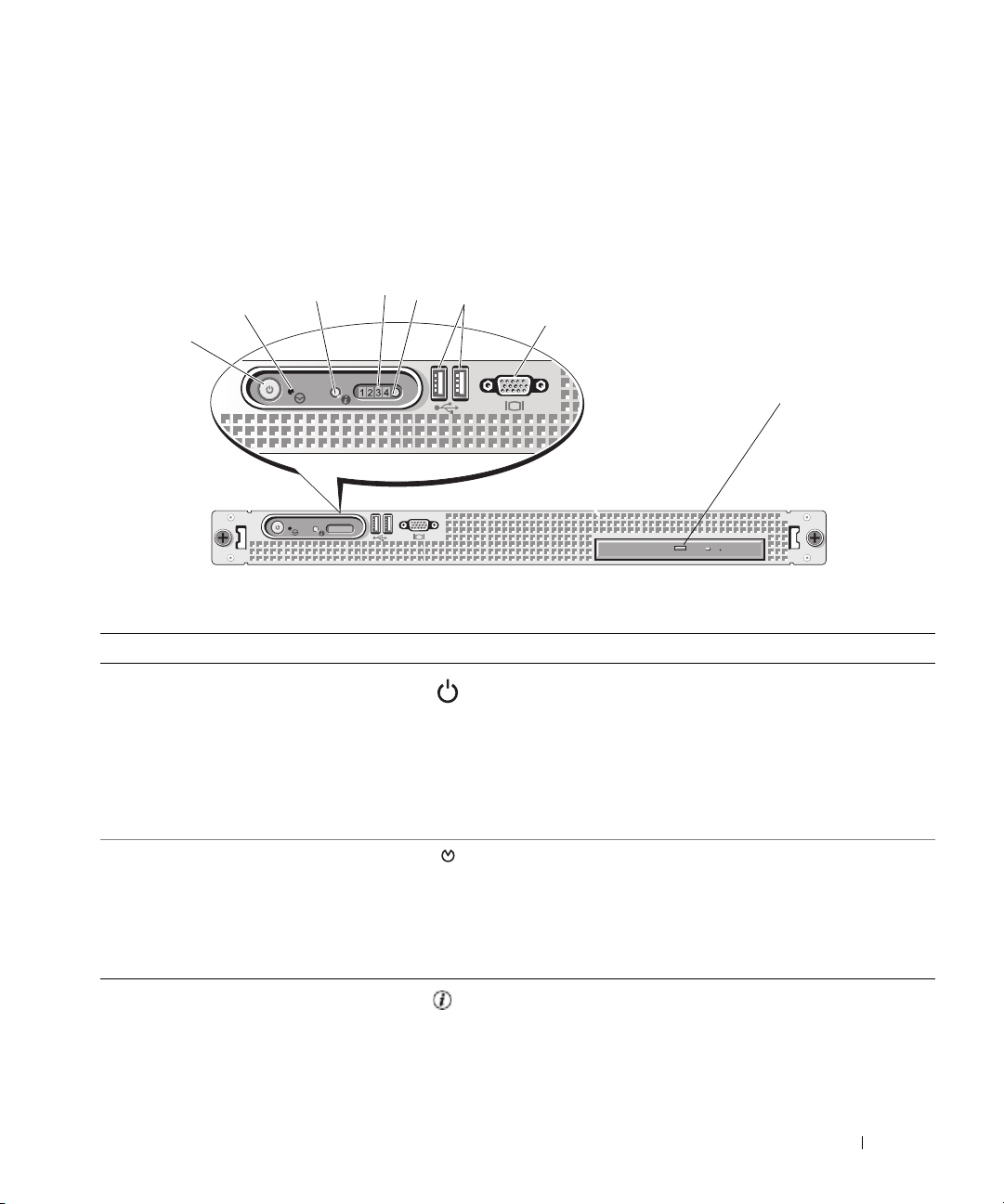
Front-Panel Features and Indicators
Figure 1-1 shows the controls, indicators, and connectors located behind the optional rack bezel on the
system's front panel.
Figure 1-1. Front-Panel Features and Indicators
2
1
Table 1-2. Front-Panel Indicators, Buttons, and Connectors
Item Indicator, Button, or Connector Icon Description
1 Power-on indicator, power
button
2 NMI button Used to troubleshoot software and device driver errors
3 System identification button The identification buttons on the front and back panels
3
4
5
6
7
8
The power button controls the DC power supply output
to the system.
NOTE: If you turn off the system using the power button
and the system is running an ACPI-compliant operating
system, the system performs a graceful shutdown before
the power is turned off. If the system is not running an
ACPI-compliant operating system, the power is turned off
immediately after the power button is pressed.
when using certain operating systems. This button can
be pressed using the end of a paper clip.
Use this button only if directed to do so by qualified
support personnel or by the operating system's
documentation.
can be used to locate a particular system within a rack.
When one of these buttons is pushed, the blue system
status indicator on the front and back blinks until one of
the buttons is pushed again.
About Your System 11
Page 12
Table 1-2. Front-Panel Indicators, Buttons, and Connectors (continued)
Item Indicator, Button, or Connector Icon Description
4 Diagnostics indicator lights (4) The four diagnostic indicator lights on the system front
panel display error codes during system startup.
5 System status indicator light Lights blue during normal system operation.
Both the systems management software and the
identification buttons located on the front and back of
the system can cause the indicator to flash blue to
identify a particular system.
Lights amber when the system needs attention due to a
problem.
6 USB connectors (2) Connects USB 2.0-compliant devices to the system.
7 Video connector Connects a monitor to the system.
8 Optical drive (optional) One optional slimline optical drive
NOTE: DVD devices are data only.
12 About Your System
Page 13
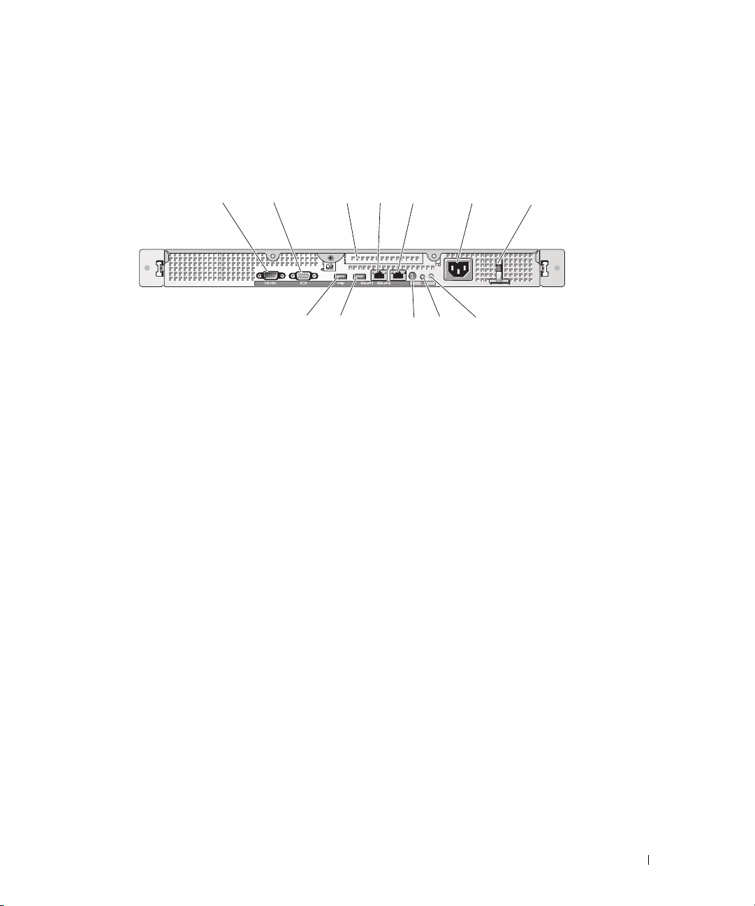
Back-Panel Features and Indicators
Figure 1-2 shows the controls, indicators, and connectors located on the system's back panel.
Figure 1-2. Back-Panel Features and Indicators
721345 6
11
12
1 serial connector 2 video connector 3 expansion slot
4 NIC1 connector 5 NIC2 connector 6 power connector
7 power cable retention bracket 8 system identification button 9 system status indicator
10 system status indicator LED
cable connector
11 USB connector 12 USB connector
10 9
Connecting External Devices
When connecting external devices to your system, follow these guidelines:
• Most devices must be connected to a specific connector and device drivers must be installed before the
device operates properly. (Device drivers are normally included with your operating system software or
with the device itself.) See the documentation that accompanied the device for specific installation
and configuration instructions.
• Always attach external devices while your system is turned off. Next, turn on any external devices
before turning on the system (unless the documentation for the device specifies otherwise).
For information about individual connectors, see "Jumpers and Connectors" on page 89. For information
about enabling, disabling, and configuring I/O ports and connectors, see "Using the System Setup Program"
on page 23.
8
Power Indicator Codes
The power button on the front panel controls the power input to the system's power supply. The power
indicator can provide information on power status (see
indicator codes.
Figure 1-1
). Table 1-3 lists the power button
About Your System 13
Page 14
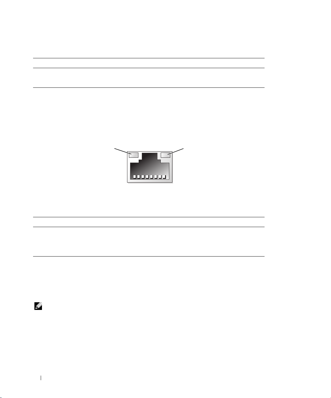
Table 1-3. Power Button Indicators
Indicator Function
On Indicates that power is supplied to the system and the system is operational.
Off Indicates that no power is supplied to the system.
NIC Indicator Codes
Each NIC on the back panel has an indicator that provides information on network activity and link
status. See Figure 1-3. Table 1-4 lists the NIC indicator codes.
Figure 1-3. NIC Indicators
1
1 link indicator 2 activity indicator
Table 1-4. NIC Indicator Codes
Indicator Indicator Code
Link and activity indicators are off The NIC is not connected to the network.
Link indicator is green The NIC is connected to a valid link partner on the network.
Activity indicator is amber blinking Network data is being sent or received.
2
Diagnostics Indicator Codes
The four diagnostic indicator lights on the system front panel display error codes during system startup.
Table 1-5 lists the causes and possible corrective actions associated with these codes. A highlighted circle
indicates the light is on; a non-highlighted circle indicates the light is off.
NOTE: Once the system completes POST, all diagnostic lights will be OFF.
14 About Your System
Page 15
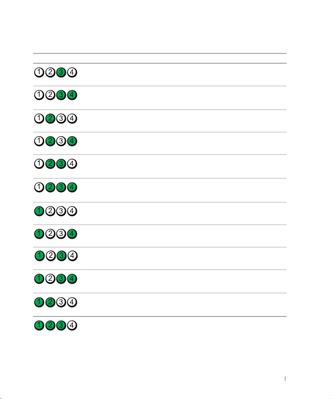
Table 1-5. Diagnostic Indicator Codes
Code Causes Corrective Action
Possible processor failure. See "Troubleshooting the Microprocessors" on page 82.
Memory failure. See "Troubleshooting System Memory" on page 76.
Possible expansion card
failure.
Possible video failure. See "Getting Help" on page 95.
Hard drive failure. Ensure that the hard drive is properly connected. See
Possible USB failure. See ""Troubleshooting a USB Device" on page 71.
No memory modules
detected.
System board failure. See "Getting Help" on page 95.
Memory configuration error. See "Troubleshooting System Memory" on page 76.
Possible system board
resource and/or system board
hardware failure.
Possible system resource
configuration error.
Other failure. Ensure that the optical drive and hard drives are properly
See "Troubleshooting an Expansion Card" on page 80.
"Troubleshooting a Hard Drive" on page 78.
See "Troubleshooting System Memory" on page 76.
See "Troubleshooting IRQ Assignment Conflicts" on
page 68. If the problem persists, see "Getting Help" on
page 95.
See "Troubleshooting IRQ Assignment Conflicts" on
page 68. If the problem persists, see "Getting Help" on
page 95.
connected. See "Troubleshooting an Optical Drive" on
page 78 or "Troubleshooting a Hard Drive" on page 78.
If the problem persists, see "Getting Help" on page 95.
About Your System 15
Page 16
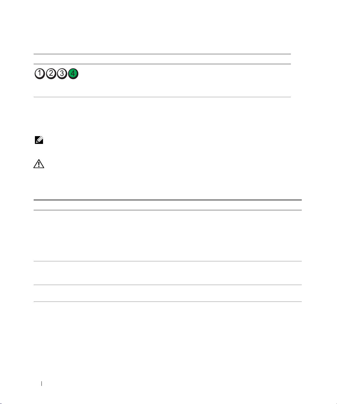
Table 1-5. Diagnostic Indicator Codes (continued)
Code Causes Corrective Action
BIOS checksum failure
detected; system is in
recovery mode.
Ensure that all network connections are functioning
properly. See ""Troubleshooting Your System" on
page 67."
If the problem persists, see ""Getting Help" on page 95."
System Messages
System messages appear on the screen to notify you of a possible problem with the system. Table 1-6 lists
the system messages that can occur and the probable cause and corrective action for each message.
NOTE: If you receive a system message that is not listed in Table 1-6, check the documentation for the application
that is running when the message appears or the operating system's documentation for an explanation of the
message and recommended action.
CAUTION: Only trained service technicians are authorized to remove the system cover and access any of the
components inside the system. See your Product Information Guide for complete information about safety
precautions, working inside the computer, and protecting against electrostatic discharge.
Table 1-6. System Messages
Message Causes Corrective Actions
Alert! Node Interleaving
disabled! Memory configuration does not support
Node Interleaving.
Attempting to update
Remote Configuration.
Please wait...
BIOS Update Attempt
Failed!
Caution! NVRAM_CLR jumper
is installed on system
board.
The memory configuration does not
support node interleaving. The
system will run but with reduced
functionality.
Remote Configuration request has
been detected and is being
processed.
Remote BIOS update attempt
failed.
NVRAM_CLR jumper is installed.
CMOS has been cleared.
Ensure that the memory modules are
installed in a configuration that
supports node interleaving. See
"Memory Module Installation
Guidelines" on page 46. If the problem
persists, see "Troubleshooting System
Memory" on page 76.
Wait until the process is complete.
Retry the BIOS update. If problem
persists, see "Getting Help" on page 95.
Remove the NVRAM_CLR jumper.
See Figure 6-1 for jumper location.
16 About Your System
Page 17

Table 1-6. System Messages (continued)
Message Causes Corrective Actions
Diskette drive n seek
failure
Diskette read failure Faulty or improperly inserted
Diskette subsystem reset
failed
Drive not ready Diskette missing from or improperly
Error: Incorrect memory
configuration.
n
CPU
System Halted!
Error: Memory failure
detected. Memory size
reduced. Replace the
faulty DIMM as soon as
possible.
Remote configuration
update attempt failed
Fatal error caused a
system reset: Please
check the system event
log for details.
Gate A20 failure Faulty keyboard controller; faulty
Incorrect configuration settings in
the System Setup program.
Faulty or improperly installed
diskette drive.
Loose diskette drive interface cable. Reconnect the diskette drive USB
diskette.
Faulty or improperly installed
diskette.
inserted in diskette drive.
Invalid memory configuration. Ensure that the memory modules are
Faulty or improperly seated memory
module(s).
System unable to process Remote
Configuration request.
Fatal system error. Check the system event log for the
system board.
Run the System Setup program to
correct the settings. See "Using the
System Setup Program" on page 23.
Replace the diskette. If the problem
persists, see "Troubleshooting a USB
Device" on page 71.
cable. See "Troubleshooting a USB
Device" on page 71.
Replace the diskette. If the problem
persists, see "Troubleshooting a USB
Device" on page 71.
Replace the diskette. If the problem
persists, see "Troubleshooting a USB
Device" on page 71.
Replace the diskette. If the problem
persists, see "Troubleshooting a USB
Device" on page 71.
installed in a valid configuration. See
"Memory Module Installation
Guidelines" on page 46. If the problem
persists, see "Troubleshooting System
Memory" on page 76.
See "Troubleshooting System Memory"
on page 76.
Retry Remote Configuration.
specific cause, then see the appropriate
section in"Troubleshooting Your
System" on page 67.
See "Getting Help" on page 95.
About Your System 17
Page 18

Table 1-6. System Messages (continued)
Message Causes Corrective Actions
General failure The operating system is unable to
carry out the command.
Invalid NVRAM
configuration, Resource
Re-allocated
Keyboard Controller
failure
Manufacturing mode
detected
Memory address line
failure at
value
expecting
Memory double word logic
failure at
value
expecting
Memory odd/even logic
failure at
value
expecting
Memory write/read failure
address
at
expecting
Memory tests terminated
by keystroke.
No boot device available Faulty or missing optical/diskette
address
address
address,
, read
value
, read
value
, read
value
read
value
value
System detected and corrected a
resource conflict.
Faulty keyboard controller; faulty
system board
System is in manufacturing mode. Reboot to take the system out of
Faulty or improperly installed
memory modules.
POST memory test terminated by
pressing the spacebar.
drive subsystem, hard drive, or harddrive subsystem, or no boot disk in
drive A.
This message is usually followed by
specific information. Note the
information and take the appropriate
action to resolve the problem.
No action is required.
See "Getting Help" on page 95.
manufacturing mode.
See "Troubleshooting System Memory"
on page 76.
Information only.
Use a bootable diskette, CD, or hard
drive. If the problem persists, see
"Troubleshooting a USB Device" on
page 71, "Troubleshooting an Optical
Drive" on page 78, and
"Troubleshooting a Hard Drive" on
page 78. See "Using the System Setup
Program" on page 23 for information
about setting the order of boot devices.
18 About Your System
Page 19

Table 1-6. System Messages (continued)
Message Causes Corrective Actions
No boot sector on hard
drive
No timer tick interrupt Faulty system board. See "Getting Help" on page 95.
Not a boot diskette No operating system on diskette. Use a bootable diskette.
PCIe Degraded Link Width
Error: Embedded
nn
Bus#
Expected Link Width is
Actual Link Width is
PCIe Degraded Link Width
Error: Slot
Expected Link Width is
Actual Link Width is
PCIe Fatal Error caused a
system reset: Slot
or
Embedded
Bus#
Please check the system
event log for details.
PCI BIOS failed to
install
Plug & Play Configuration
Error
/Dev#nn/Func
nn
/Dev#nn/Func
n
n
n
n
Incorrect configuration settings in
System Setup program, or no
operating system on hard drive.
Faulty or improperly installed PCIe
card in the specified slot.
n
n
Faulty or improperly installed PCIe
card in the specified slot.
n
n
Faulty or improperly installed PCIe
card in the specified slot.
PCI device BIOS (Option ROM)
checksum failure is detected during
shadowing. Loose cables to
expansion card(s); faulty or
improperly installed expansion card.
Error encountered in initializing
PCI device; faulty system board.
Check the hard-drive configuration
settings in the System Setup program.
See "Using the System Setup Program"
on page 23. If necessary, install the
operating system on your hard drive.
See your operating system
documentation.
Reseat the PCIe card in the specified
slot number. See "Installing an
Expansion Card" on page 44. If the
problem persists, see "Getting Help"
on page 95.
Reseat the PCIe card in the specified
slot number. See "Installing an
Expansion Card" on page 44. If the
problem persists, see "Getting Help"
on page 95.
Reseat the PCIe card in the specified
slot number. See "Installing an
Expansion Card" on page 44. If the
problem persists, see "Getting Help"
on page 95.
Reseat the expansion cards. Ensure
that all appropriate cables are securely
connected to the expansion cards. If
the problem persists, see
"Troubleshooting an Expansion Card"
on page 80.
Install the NVRAM_CLR jumper and
reboot the system. See Figure 6-1 for
jumper location. If the problem
persists, see "Troubleshooting an
Expansion Card" on page 80.
About Your System 19
Page 20

Table 1-6. System Messages (continued)
Message Causes Corrective Actions
Read fault
Requested sector not
found
Remote configuration
update attempt failed
ROM bad checksum =
address
n
SATA port
drive not found
Sector not found
Seek error
Seek operation failed
Shutdown failure Shutdown test failure. See "Troubleshooting System Memory"
The amount of system
memory has changed
This system supports only
Opteron 2000 series
processors.
Time-of-day clock stopped Faulty battery or faulty chip. See "Troubleshooting the System
hard disk
The operating system cannot read
from the diskette or hard drive, the
system could not find a particular
sector on the disk, or the requested
sector is defective.
System unable to process Remote
Configuration request.
Expansion card improperly installed
or faulty.
SATA cables are not properly seated,
or drive missing.
Faulty diskette or hard drive. See "Troubleshooting a USB Device"
Memory has been added or removed
or a memory module may be faulty.
Microprocessor(s) is not supported
by the system.
Replace the diskette. Ensure that the
diskette and hard drive cables are
properly connected. See
"Troubleshooting a USB Device" on
page 71, "Troubleshooting an Optical
Drive" on page 78, or "Troubleshooting
a Hard Drive" on page 78 for the
appropriate drive(s) installed in your
system.
Retry Remote Configuration.
Reseat the expansion cards. Ensure
that all appropriate cables are securely
connected to the expansion cards. If
the problem persists, see
"Troubleshooting an Expansion Card"
on page 80.
See "Troubleshooting a Hard Drive" on
page 78.
on page 71 or "Troubleshooting a Hard
Drive" on page 78 for the appropriate
drive.
on page 76.
If memory has been added or removed,
this message is informative and can be
ignored. If memory has not been added
or removed, check the SEL to
determine if single-bit or multi-bit
errors were detected and replace the
faulty memory module. See
"Troubleshooting System Memory" on
page 76.
Install a supported microprocessor or
microprocessor combination. See
"Processors" on page 50.
Battery" on page 74.
20 About Your System
Page 21

Table 1-6. System Messages (continued)
Message Causes Corrective Actions
Time-of-day not set please run SETUP program
Timer chip counter 2
failed
Unsupported CPU
combination
Unsupported CPU stepping
detected
Utility partition not
available
n
Warning: DIMM
faulty and disabled.
Total memory size is
reduced!
Warning! No microcode
update loaded for
processor
Warning: One or more
faulty DIMMs found on
n
CPU
Warning: The installed
memory configuration is
not optimal. For more
information on valid
memory configurations,
please see the system
documentation on the
technical support web
site.
Write fault
Write fault on selected
drive
and n are
n
Incorrect Time or Date settings;
faulty system battery.
Faulty system board. See "Getting Help" on page 95.
Microprocessor(s) is not supported
by the system.
The <F10> key was pressed during
POST, but no utility partition exists
on the boot hard drive.
Faulty or improperly seated memory
module(s).
Microcode update failed. Update the BIOS firmware. See
Faulty or improperly seated memory
module(s) used by CPUn.
Invalid memory configuration. The
system will run but with reduced
functionality.
Faulty diskette, optical/diskette
drive assembly, hard drive, or harddrive subsystem.
Check the Time and Date settings. See
"Using the System Setup Program" on
page 23. If the problem persists,
replace the system battery. See "System
Battery" on page 59.
Install a supported microprocessor or
microprocessor combination. See
"Processors" on page 50.
Create a utility partition on the boot
hard drive. See the CDs that came
with your system.
See "Troubleshooting System Memory"
on page 76.
"Getting Help" on page 95.
See "Troubleshooting System Memory"
on page 76.
Ensure that the memory modules are
installed in a valid configuration. See
"Memory Module Installation
Guidelines" on page 46. If the problem
persists, see "Troubleshooting System
Memory" on page 76.
See "Troubleshooting a USB Device"
on page 71, "Troubleshooting an
Optical Drive" on page 78, or
"Troubleshooting a Hard Drive" on
page 78.
NOTE: For the full name of an abbreviation or acronym used in this table, see the "Glossary" on page 121.
About Your System 21
Page 22

Warning Messages
A warning message alerts you to a possible problem and prompts you to respond before the system
continues a task. For example, before you format a diskette, a message will warn you that you may lose all
data on the diskette. Warning messages usually interrupt the task and require you to respond by typing
(yes) or
n (no).
NOTE: Warning messages are generated by either the application or the operating system. For more information,
see the documentation that accompanied the operating system or application.
Diagnostics Messages
When you run system diagnostics, an error message may result. Diagnostic error messages are not
covered in this section. Record the message on a copy of the Diagnostics Checklist in "Getting Help" on
page 95, and then follow the instructions in that section for obtaining technical assistance.
Alert Messages
Systems management software generates alert messages for your system. Alert messages include
information, status, warning, and failure messages for drive, temperature, fan, and power conditions. For
more information, see the systems management software documentation.
y
22 About Your System
Page 23

Using the System Setup Program
After you set up your system, run the System Setup program to familiarize yourself with your system
configuration and optional settings. Record the information for future reference.
You can use the System Setup program to:
• Change the system configuration stored in NVRAM after you add, change, or remove hardware
• Set or change user-selectable options—for example, the time or date
• Enable or disable integrated devices
• Correct discrepancies between the installed hardware and configuration settings
Entering the System Setup Program
1
Turn on or restart your system.
2
Press <F2> immediately after you see the following message (you may have to press the <F2>
key more than once):
<F2> = System Setup
If your operating system begins to load before you press <F2>, allow the system to finish booting,
and then restart your system and try again.
NOTE: To ensure an orderly system shutdown, see the documentation that accompanied your operating
system.
Responding to Error Messages
You can enter the System Setup program by responding to certain error messages. If an error message
appears while the system is booting, make a note of the message. Before entering the System Setup
program, see "System Messages" on page 16 for an explanation of the message and suggestions for
correcting errors.
NOTE: After installing a memory upgrade, it is normal for your system to send a message the first time you
start your system.
Using the System Setup Program 23
Page 24
Using the System Setup Program
Table 2-1 lists the keys that you use to view or change information on the System Setup program screens
and to exit the program.
Table 2-1. System Setup Program Navigation Keys
Keys Action
Up arrow or <Shift><Tab> Moves to the previous field.
Down arrow or <Tab> Moves to the next field.
Spacebar, <+>, <
right arrows
<Enter> From the main menu, selects an option that has a
<Esc> From a submenu, returns the program to the main
<F1> Displays the System Setup program
NOTE: For most of the options, any changes that you make are recorded but do not take effect until you restart the
system.
–>, left and
Cycles through the settings in a field. In many fields,
you can also type the appropriate value.
submenu, such as Memory Information.
menu.
From the main menu, exits the System Setup
program and restarts the system if any changes were
made.
's help file.
System Setup Options
Main Screen
When you enter the System Setup program, the main System Setup program screen appears (see
Figure 2-1).
24 Using the System Setup Program
Page 25
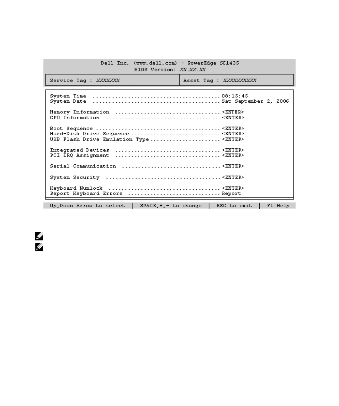
Figure 2-1. Main System Setup Program Screen
Table 2-2 lists the options and descriptions for the information fields that appear on the main System
Setup program screen. For related information, see "System Security Screen Options" on page 29.
NOTE: The options for the System Setup program change based on the system configuration.
NOTE: The System Setup program defaults are listed under their respective options, where applicable.
Table 2-2. System Setup Program Options
Option Description
System Time Resets the time on the system's internal clock.
System Date Resets the date on the system's internal calendar.
Memory Information Displays information related to installed memory. See "Memory Information
Screen" on page 27.
CPU Information Displays information related to microprocessors (speed, cache size, and so on). See
"CPU Information Screen" on page 27.
Using the System Setup Program 25
Page 26

Table 2-2. System Setup Program Options (continued)
Option Description
Boot Sequence Determines the order in which the system searches for boot devices during system
startup. Available options can include the diskette drive, CD drive, hard drives, and
network.
NOTE: System boot is not supported from an external device attached to a SAS or
SCSI adapter. See support.dell.com for the latest support information about booting
from external devices.
Hard-Disk Drive
Sequence
USB Flash Drive
Emulation Type
Auto
default)
(
Boot Sequence Retry If this field is enabled and the system has failed to boot, the system will reattempt
Integrated Devices See "Integrated Devices Screen" on page 28.
PCI IRQ Assignment Displays a screen to change the IRQ assigned to each of the integrated devices on
Serial Communication
(Off default)
System Security Displays a screen to configure the system password and setup password features.
Keyboard NumLock
On
default)
(
Report Keyboard Errors
Report
default)
(
Determines the order in which the system searches the hard drives during system
startup. The selections depend on the hard drives installed in your system.
Determines the emulation type for a USB flash drive. Hard disk allows the USB
flash drive to act as a hard drive. Floppy allows the USB flash drive to act as a
removal diskette drive. Auto automatically chooses an emulation type.
to boot after 30 seconds.
the PCI bus, and any installed expansion card that requires an IRQ.
Options are On with Console Redirection via COM2, and Off.
See "System Security Screen" on page 29, "Using the System Password" on page 30,
and "Using the Setup Password" on page 32 for more information.
Determines whether your system starts up with the NumLock mode activated on
101- or 102-key keyboards (does not apply to 84-key keyboards).
Enables or disables reporting of keyboard errors during the POST. Select Report for
host systems that have keyboards attached. Select Do Not Report to suppress all
error messages relating to the keyboard or keyboard controller during POST. This
setting does not affect the operation of the keyboard itself if a keyboard is attached
to the system.
26 Using the System Setup Program
Page 27

Memory Information Screen
Table 2-3 lists the descriptions for the information fields that appear on the Memory Information
screen.
Table 2-3. Memory Information Screen
Option Description
System Memory Size Displays the amount of system memory.
System Memory Type Displays the type of system memory.
System Memory Speed Displays the system memory speed.
Video Memory Displays the amount of video memory.
System Memory Testing This option determines whether system memory tests are run at
system boot. Options are Enabled and Disabled.
Node Interleaving If this field is enabled, memory interleaving is supported if a
symmetric memory configuration is installed. If this field is set to
disabled (the default), the system can support Non-Uniform
Memory Architecture (NUMA) memory access. See "Memory
Module Installation Guidelines" on page 46.
CPU Information Screen
Table 2-4 lists the options and descriptions for the information fields that appear on the CPU
Information screen.
Table 2-4. CPU Information Screen
Option Description
64-bit Specifies if the installed processor(s) support 64-bit extensions.
Core Speed Displays the clock speed of the processor(s).
Bus Speed Displays the bus speed of the processor(s).
Demand-Based Power
Management
(Disabled default)
Processor X ID Displays the model number of the processor. A submenu displays
Enables or disables demand-based power management. When
enabled, the CPU Performance State tables will be reported to the
operating system; when disabled, the CPU Performance State
tables will not be reported to the operating system. If any of the
CPUs do not support demand-based power management, the field
will become read-only, and automatically set to Disabled.
the amount of level 2 cache and number of cores.
Using the System Setup Program 27
Page 28

Enabling AMD™ PowerNow!™ Technology
PowerNow! technology controls your system’s processor performance automatically, dynamically
adjusting the operating frequency and voltage according to the task at hand. When an application does
not require full performance, significant amounts of power can be saved. Performance is designed to still
be responsive, with maximum processor performance being delivered when required, and automatic
power savings when possible. (PowerNow! support is dependent on the operating system and version
used on your system.)
To enable the PowerNow! feature, run the System Setup Program and enable the Demand-Based Power
Management option on the CPU Information screen.
Additionally, for Microsoft
®
Windows® operating systems, you will need to install the PowerNow! driver
to enable this feature. The driver is available on the Dell OpenManage Service and Diagnostic CD
provided with your system and at support.dell.com.
Integrated Devices Screen
Table 2-5 lists the options and descriptions for the information fields that appear on the Integrated
Devices screen.
Table 2-5. Integrated Devices Screen Options
Option Description
Embedded SATA
Controller (Off default)
IDE CD-ROM Controller
(Auto default)
User-Accessible USB Ports
(All Ports On default)
Embedded Gb NIC1
(Enabled with PXE
default)
MAC Address Displays the MAC address for NIC1. This field does not have user-selectable
Embedded Gb NIC2
(Enabled without PXE
default)
MAC Address Displays the MAC address for NIC2. This field does not have user-selectable
Allows the integrated SATA controller to be set to Off or ATA mode.
Enables the integrated IDE controller. When set to
integrated IDE controller is enabled if IDE devices are attached to the channel and
an external IDE controller is not detected.
Auto
, each channel of the
NOTE: This CD-ROM option will not appear on this menu screen if your system does
not include this optional device.
Enables or disables the system's user-accessible ports. Options are All Ports On or
All Ports Off. Disabling the USB ports makes system resources available for other
devices.
Enables or disables the system's integrated NIC1. Options are Enabled without
PXE, Enabled with PXE, and Disabled. PXE support allows the system to boot
from the network. Changes take effect after the system reboots.
settings.
Enables or disables the system's integrated NIC2. Options are Enabled without
PXE, Enabled with PXE, and Disabled. PXE support allows the system to boot
from the network. Changes take effect after the system reboots.
settings.
28 Using the System Setup Program
Page 29

System Security Screen
Table 2-6 lists the options and descriptions for the information fields that appear on the System Security
screen.
Table 2-6. System Security Screen Options
Option Description
System Password Displays the current status of your system's password security feature and allows
you to assign and verify a new system password.
NOTE: See "Using the System Password" on page 30 for instructions on assigning a
system password and using or changing an existing system password.
Setup Password Restricts access to the System Setup program in the same way that you restrict
access to your system using the system password feature.
NOTE: See "Using the Setup Password" on page 32 for instructions on assigning a
setup password and using or changing an existing setup password.
Password Status Setting the Setup Password option to Enabled prevents the system password from
being changed or disabled at system start-up.
To lock the system password, assign a setup password in the Setup Password option
and then change the Password Status option to Locked. In this state, you cannot
change the system password using the System Password option and cannot be
disabled at system start-up by pressing <Ctrl><Enter>.
To unlock the system password, enter the setup password in the Setup Password
field and then change the Password Status option to Unlocked. In this state, you
can disable the system password at system start-up by pressing <Ctrl><Enter>
and then change the password using the System Password option.
Power Button
NMI Button
Turns system's power off and on.
• If you turn off the system using the power button and the system is running an
ACPI-compliant operating system, the system can perform an orderly shutdown
before power is turned off.
• If the system is not running an ACPI-compliant operating system, power is turned
off immediately after the power button is pressed.
The button is enabled in the System Setup program. When disabled, the button
can only turn on system power.
NOTE: You can still turn on the system by using the power button, even if the Power
Button option is set to Disabled.
NOTICE: Use the NMI button only if directed to do so by qualified support
personnel or by the operating system's documentation. Pressing this button
halts the operating system and displays a diagnostic screen.
Enables or disables the NMI feature.
Using the System Setup Program 29
Page 30

Table 2-6. System Security Screen Options (continued)
Option Description
AC Power Recovery
(Last default)
Determines how the system reacts when power is restored to the system. If system
is set to Last, the system returns to the last power state. On turns on the system
after power is restored. When set to Off, the system remains off after power is
restored.
Exit Screen
After you press <Esc> to exit the System Setup program, the Exit screen displays the following options:
•
Save Changes and Exit
• Discard Changes and Exit
• Return to Setup
System and Setup Password Features
NOTICE: The password features provide a basic level of security for the data on your system. If your data requires
more security, use additional forms of protection, such as data encryption programs.
NOTICE: Anyone can access the data stored on your system if you leave the system running and unattended
without having a system password assigned or if you leave your system unlocked so that someone can disable the
password by changing a jumper setting.
Your system is shipped to you without the system password feature enabled. If system security is a
concern, operate your system only with system password protection.
To change or delete an existing password, you must know the password (see "Deleting or Changing an
Existing System Password" on page 32). If you forget your password, you cannot operate your system or
change settings in the System Setup program until a trained service technician changes the password
jumper setting to disable the passwords, and erases the existing passwords. This procedure is described in
"Disabling a Forgotten Password" on page 90.
Using the System Password
After a system password is assigned, only those who know the password have full use of the system.
When the System Password option is set to Enabled, the system prompts you for the system password
after the system starts.
Assigning a System Password
Before you assign a system password, enter the System Setup program and check the System Password
option.
30 Using the System Setup Program
Page 31

When a system password is assigned, the setting shown for the System Password option is Enabled. If
the setting shown for the Password Status is Unlocked, you can change the system password. If the
Password Status option is Locked, you cannot change the system password. When the system password
feature is disabled by a jumper setting, the system password is Disabled, and you cannot change or enter
a new system password.
When a system password is not assigned and the password jumper on the system board is in the enabled
(default) position, the setting shown for the System Password option is Not Enabled and the Password
Status field is Unlocked. To assign a system password:
1
Verify that the
2
Highlight the
3
Type your new system password.
Password Status
System Password
option is set to
Unlocked
.
option and press <Enter>.
You can use up to 32 characters in your password.
As you press each character key (or the spacebar for a blank space), a placeholder appears in the field.
The password assignment is not case-sensitive. However, certain key combinations are not valid. To
erase a character when entering your password, press <Backspace> or the left-arrow key.
NOTE: To escape from the field without assigning a system password, press <Enter> to move to another field,
or press <Esc> at any time prior to completing step 5.
4
Press <Enter>.
5
To confirm your password, type it a second time and press <Enter>.
The setting shown for the
System Password
changes to
Enabled
. Exit the System Setup program and
begin using your system.
6
Either reboot your system now for your password protection to take effect or continue working.
NOTE: Password protection does not take effect until you reboot the system.
Using Your System Password to Secure Your System
NOTE: If you have assigned a setup password (see "Using the Setup Password" on page 32"), the system accepts
your setup password as an alternate system password.
When the Password Status option is set to Unlocked, you have the option to leave the password security
enabled or to disable the password security.
To leave the password security enabled:
1
Turn on or reboot your system by pressing <Ctrl><Alt><Del>.
2
Type your password and press <Enter>.
To disable the password security:
1
Turn on or reboot your system by pressing <Ctrl><Alt><Del>.
2
Type your password and press <Ctrl><Enter>.
Using the System Setup Program 31
Page 32

When the Password Status option is set to Locked whenever you turn on your system or reboot your
system by pressing <Ctrl><Alt><Del>, type your password and press <Enter> at the prompt.
After you type the correct system password and press <Enter>, your system operates as usual.
If an incorrect system password is entered, the system displays a message and prompts you to re-enter
your password. You have three attempts to enter the correct password. After the third unsuccessful
attempt, the system displays an error message showing the number of unsuccessful attempts and that
the system has halted and will shut down. This message can alert you to an unauthorized person
attempting to use your system.
Even after you shut down and restart the system, the error message continues to be displayed until the
correct password is entered.
NOTE: You can use the Password Status option in conjunction with the System Password and Setup Password
options to further protect your system from unauthorized changes.
Deleting or Changing an Existing System Password
1
When prompted, press <Ctrl><Enter> to disable the existing system password.
If you are asked to enter your setup password, contact your network administrator.
2
Enter the System Setup program by pressing <F2> during POST.
3
Select the
4
When prompted, type the system password.
5
Confirm that
If
Not Enabled
Enabled
System Security
screen field to verify that the
Not Enabled
is displayed for the
is displayed for the
is displayed for the
System Password
System Password
option, press the <Alt><b> key combination to restart
Password Status
System Password
option.
option is set to
option, the system password has been deleted. If
Unlocked
the system, and then repeat steps 2 through 5.
.
Using the Setup Password
Read the information in the following sections to assign or change your setup password.
Assigning a Setup Password
You can assign (or change) a setup password only when the Setup Password option is set to Not Enabled.
To assign a setup password, highlight the Setup Password option and press the <+> or <–> key. The
system prompts you to enter and verify the password. If a character is illegal for password use, the system
beeps.
NOTE: The setup password can be the same as the system password. If the two passwords are different, the setup
password can be used as an alternate system password. However, the system password cannot be used in place of
the setup password.
You can use up to 32 characters in your password.
As you press each character key (or the spacebar for a blank space), a placeholder appears in the field.
32 Using the System Setup Program
Page 33

The password assignment is not case-sensitive. However, certain key combinations are not valid. If you
enter one of these combinations, the system beeps. To erase a character when entering your password,
press <Backspace> or the left-arrow key.
After you verify the password, the Setup Password setting changes to Enabled. The next time you enter
the System Setup program, the system prompts you for the setup password.
A change to the Setup Password option becomes effective immediately (restarting the system is not
required).
Operating With a Setup Password Enabled
If Setup Password is set to Enabled, you must enter the correct setup password before you can modify
most of the System Setup options. When you start the System Setup program, the program prompts you
to enter a password.
If you do not enter the correct password in three attempts, the system lets you view, but not modify, the
System Setup screens—with the following exception: If System Password is not set to Enabled and is not
locked through the Password Status option, you can assign a system password.
NOTE: You can use the Password Status option in conjunction with the Setup Password option to protect the
system password from unauthorized changes.
Deleting or Changing an Existing Setup Password
1
Enter the System Setup program and select the
2
Highlight the
<Enter> twice to clear the existing setup password.
The setting changes to
Setup Password
Not Enabled
option, press <Enter> to access the setup password window, and press
.
System Security
option.
3
If you want to assign a new setup password, perform the steps in "Assigning a Setup Password" on
page 32.
Disabling a Forgotten Password
See "Disabling a Forgotten Password" on page 90.
Baseboard Management Controller Configuration
The Baseboard Management Controller (BMC) enables configuring, monitoring, and recovery of systems
remotely. BMC provides the following features:
• Uses the system’s integrated NIC
• Fault logging and SNMP alerting
• Access to system event log and sensor status
• Control of system functions including power on and off
Using the System Setup Program 33
Page 34

• Support is independent of the system’s power or operating state
• Provides text console redirection for system setup, text-based utilities, and operating system consoles
NOTE: To remotely access the BMC through the integrated NIC, you must connect the network connection to
integrated NIC1.
For additional information on using BMC, see the documentation for the BMC and systems management
applications.
Entering the BMC Setup Module
1
Turn on or restart your system.
2
Press <
If your operating system begins to load before you press <
booting, and then restart your system and try again.
Ctrl-E
> when prompted after POST.
Crtl-E
>, allow the system to finish
BMC Setup Module Options
For information about the BMC Setup Module options and how to configure the emergency management
port (EMP), see the
BMC User’s Guide
.
34 Using the System Setup Program
Page 35

Installing System Components
This section describes how to install the following system components:
• Front bezel
• System cover
• Cooling shroud
• Cooling fan modules
• Power supply
• Expansion cards
• System memory
• Processors
• Optical drive
• Hard drives
• Boot drive
• SAS controller card
• System battery
• Risers
• Control panel assembly
• System board
Recommended Tools
You may need the following items to perform the procedures in this section:
• Key to the system keylock
• #2 Phillips screwdriver
• T10 Torx driver
• Small flat-blade screwdriver
• Wrist grounding strap
Installing System Components 35
Page 36

Inside the System
CAUTION: Only trained service technicians are authorized to remove the system cover and access any of the
components inside the system. See your Product Information Guide for complete information about safety
precautions, working inside the computer, and protecting against electrostatic discharge.
CAUTION: The memory modules can become extremely hot during normal operation. Allow the modules
sufficient time to cool before handling.
In Figure 3-1, the bezel, system cover, and cooling shroud are removed to provide an interior view of the
system.
Figure 3-1. Inside the System
2
1
3
4
5
8
7
1 power supply 2 cooling shroud 3 expansion card
4 memory modules (8) 5 heatsink/microprocessor (2) 6 cooling fan modules (2)
7 optical drive (optional) 8 3.5-inch hard drive bays (2)
6
Several hardware options, such as the microprocessors and memory, are installed directly on the system
board. The riser card accommodates one half-length expansion card. For more information, see
"Expansion Cards" on page 44.
36 Installing System Components
Page 37

The system provides space for one optional slimline optical drive. For more information, see "Installing
the Optical Drive in the System" on page 54.
The hard-drive bays provide space for one or two 3.5-inch hard drives. The hard drives connect to the
SATA controller or the system board, or an optional SAS controller card. For more information, see "Hard
Drives" on page 55.
During an installation or troubleshooting procedure, you may be required to change a jumper setting.
For more information, see "Jumpers and Connectors" on page 89.
NOTE: There are no hot-pluggable components inside this system.
Removing and Replacing the Front Bezel
The system front panel is enclosed by an optional bezel. To access the optional optical drive, you must
remove the bezel.
NOTE: You do not need to remove the front bezel to remove the system cover and access internal components.
1
Using the system key, unlock the bezel.
2
Press the tab at the left end of the bezel.
3
Rotate the left end of the bezel away from the system to release the right end of the bezel.
4
Pull the bezel away from the system. See Figure 3-2.
Figure 3-2. Removing the Bezel
1
1 key lock 2 bezel
To replace the front bezel, perform the preceding steps in reverse.
2
Installing System Components 37
Page 38

Opening and Closing the System
CAUTION: Only trained service technicians are authorized to remove the system cover and access any of the
components inside the system. See your Product Information Guide for complete information about safety
precautions, working inside the computer, and protecting against electrostatic discharge.
CAUTION: Whenever you need to lift the system, get others to assist you. To avoid injury, do not attempt to lift the
system by yourself.
CAUTION: The memory modules can become extremely hot during normal operation. Allow the modules
sufficient time to cool before handling.
Opening the System
To upgrade or troubleshoot the system, remove the system cover to gain access to internal components.
1
Turn off the system and attached peripherals, and disconnect the system from the electrical outlet and
peripherals.
2
Rotate the latch release lock on the latch in a counter clockwise direction to the unlocked position. See
Figure 3-3.
3
Lift up on the latch on top of the system and slide the cover back. See Figure 3-3.
4
Grasp the cover on both sides and carefully lift the cover away from the system.
Figure 3-3. Removing the Cover
1
1 latch 2 latch release lock 3 J hooks
38 Installing System Components
2
3
Page 39

Closing the System
1
Lift up the latch on the cover.
2
Align the cover with the left and right edges of the system and offset it slightly towards the back of the
system, so that the pins on the inner edge of the cover are aligned with the chassis J hooks. See
Figure 3-3.
3
Lower the cover onto the chassis and close the latch.
4
Rotate the latch release lock in a clockwise direction to secure the cover.
Cooling Shroud
The cooling shroud covers the memory modules (DIMMs) and the processor(s).
Removing the Cooling Shroud
CAUTION: Only trained service technicians are authorized to remove the system cover and access any of the
components inside the system. See your Product Information Guide for complete information about safety
precautions, working inside the computer, and protecting against electrostatic discharge.
CAUTION: The memory modules are hot to the touch for some time after the system has been powered down.
Allow time for the memory modules to cool before handling them. Handle the memory modules by the card edges
and avoid touching the components on the memory module.
NOTICE: Never operate your system with the cooling shroud removed. Overheating of the system can develop
quickly resulting in a shutdown of the system and the loss of data.
1
Turn off the system and attached peripherals, and disconnect the system from the electrical outlet and
peripherals.
2
Open the system. See "Opening and Closing the System" on page 38.
3
Grasp the shroud by the blue lift points and carefully lift the shroud straight up and away from the
system. See Figure 3-4.
Installing System Components 39
Page 40

Figure 3-4. Cooling Shroud
1
1 cooling shroud 2 locator pins (6)
Replacing the Cooling Shroud
1
To install the cooling shroud, align the edges of the shroud with the six locator pins on the system
board. See Figure 3-4.
2
Lower the shroud into place over the system board.
3
Close the system. See "Opening and Closing the System" on page 38.
2
Cooling Fan Modules
This system contains two cooling fan modules, each comprised of two dual-rotor fans.
Removing a Cooling Fan Module
CAUTION: Only trained service technicians are authorized to remove the system cover and access any of the
components inside the system. See your Product Information Guide for complete information about safety
precautions, working inside the computer, and protecting against electrostatic discharge.
1
Turn off the system and attached peripherals, and disconnect the system from the electrical outlet and
peripherals.
2
Open the system. See "Opening and Closing the System" on page 38.
3
Remove the cooling shroud. See "Removing the Cooling Shroud" on page 39.
40 Installing System Components
Page 41

4
Unplug the fan module power connector from the system board. See Figure 3-5.
5
Remove the screw from the fan module retention plate and remove the retention plate from the
chassis.
6
Lift the fan module straight up from the chassis.
Figure 3-5. Removing and Installing a Cooling Fan Module
2
1
1 fan module retention plates (2) 2 retention plate screw (2) 3 fan power cable
4 cooling fan modules (2)
3
4
Replacing a Cooling Fan Module
1
With the fan module label facing upwards and the arrow on the fan module pointing towards the back
of the system, place the fan module into the chassis. See Figure 3-5.
2
Reinstall the fan module retention plate. The four pins on the plate fit into the corresponding holes in
the fan modules.
3
Secure the retention plate with the Phillips screw.
4
Connect the fan module power cable to the power connector on the system board.
Ensure that the fan module power cable is resting in the notch in the chassis brace.
Installing System Components 41
Page 42

5
Reinstall the cooling shroud. See "Replacing the Cooling Shroud" on page 40.
6
Close the system. See "Opening and Closing the System" on page 38.
Power Supply
Removing the Power Supply
1
Turn off the system and attached peripherals, and disconnect the system from the electrical outlet and
peripherals.
2
Open the system. See "Opening and Closing the System" on page 38.
3
Disconnect the power cable from the power supply and remove the cable from the cable retention
bracket.
NOTICE: On a rack system, you may need to temporarily unlatch and lift the cable management arm. For
information about the cable management arm, see the system’s Rack Installation Guide.
4
Disconnect the two power supply cables from the POWER1 and POWER2 connectors on the system
board. See Figure 6-1.
5
If applicable, disconnect the hard drive power cables from the hard drive(s).
6
Remove the screw at the front of the power supply that secures the power supply to the chassis. See
Figure 3-6.
7
Slide the power supply toward the front of the system and remove it from the system.
42 Installing System Components
Page 43

Figure 3-6. Removing and Installing a Power Supply
2
1
1 hard-drive power cables (2) 2 retention screw 3 power supply
4 POWER2 connector 5 POWER1 connector
3
5
4
Installing the Power Supply
NOTICE: On a rack system, you may need to temporarily unlatch and lift the cable management arm. For
information about the cable management arm, see the system’s Rack Installation Guide.
NOTICE: For more information about the power cable retention bracket, see Getting Started With Your System.
1
Lower the power supply into the system and slide the power supply into place against the back panel of
the system. See Figure 3-6.
2
Reinstall the screw that secures the power supply to the chassis.
3
Connect the two power supply cables to the POWER1 and POWER2 connectors on the system board.
See Figure 3-6.
4
If applicable, route the hard drive power cables through the oval opening in the chassis brace and
connect them to the hard drives.
5
Close the system. See "Closing the System."
Installing System Components 43
Page 44

Expansion Cards
The system supports one half-length expansion card. Two different PCI riser board configurations are
available:
• The PCIe riser has one x8-lane width PCIe expansion slot.
• The PCI-X riser has one 64-bit/133-MHz expansion slot.
Installing an Expansion Card
CAUTION: Only trained service technicians are authorized to remove the system cover and access any of the
components inside the system. See your Product Information Guide for complete information about safety
precautions, working inside the computer, and protecting against electrostatic discharge.
1
Unpack the expansion card and prepare it for installation.
For instructions, see the documentation accompanying the card.
2
Turn off the system, including any attached peripherals, and disconnect the system from the electrical
outlet.
3
Open the system. See "Opening and Closing the System" on page 38.
4
If you are adding a new card, open the expansion-card latch and remove the filler bracket. See
Figure 3-7.
5
Install the expansion card. See Figure 3-7.
a
Position the expansion card so that the card-edge connector aligns with the expansion-card
connector on the riser board.
b
Insert the card-edge connector firmly into the expansion-card connector until the card is fully
seated.
c
When the card is seated in the connector, close the expansion-card latch.
6
Connect any cables to the expansion card.
NOTICE: If you are installing a SAS RAID controller card, route the SAS cables though the oval opening in the
chassis brace and connect the cables to the SAS connectors on the hard drives. Secure the cables to the
clips on the edge of the cooling shroud.
See the documentation that came with the card for information about its cable connections.
7
Close the system. See "Opening and Closing the System" on page 38.
44 Installing System Components
Page 45

Figure 3-7. Installing an Expansion Card
3
2
1
1 riser board 2 expansion-card connector 3 card-edge connector
4 expansion card 5 expansion-card latch
4
5
Removing an Expansion Card
CAUTION: Only trained service technicians are authorized to remove the system cover and access any of the
components inside the system. See your Product Information Guide for complete information about safety
precautions, working inside the computer, and protecting against electrostatic discharge.
1
Turn off the system, including any attached peripherals, and disconnect the system from the electrical
outlet.
2
Open the system. See "Opening and Closing the System" on page 38.
3
Disconnect all cables from the card.
4
Remove the expansion card:
a
Open the expansion-card latch. See Figure 3-7.
b
Grasp the expansion card by its edges, and carefully remove it from the expansion-card connector.
Installing System Components 45
Page 46

5
If you are removing the card permanently, install a metal filler bracket over the empty expansion slot
opening and close the expansion-card latch.
NOTE: You must install a filler bracket over an empty expansion slot to maintain Federal Communications
Commission (FCC) certification of the system. The brackets also keep dust and dirt out of the system and aid in
proper cooling and airflow inside the system.
6
Close the system. See "Opening and Closing the System" on page 38.
System Memory
You can upgrade your system memory to a maximum of 32 GB by installing 667-MHz registered DDR-II
memory modules (DIMMs) in sets of 512-MB, 1-GB, 2-GB, or 4-GB modules. The eight memory sockets
are located on the system board under the cooling shroud. Each processor has four memory channels,
organized in sets of two channels.
Your system hardware supports Non-Uniform Memory Architecture (NUMA) if two processors are
installed. Each processor has its own memory controller and local memory for reduced access times, but
it can also access memory from another processor. This architecture improves system performance if an
operating system is installed that supports this feature.
NOTICE: To enable NUMA, run the System Setup program and disable the Node Interleaving option. See "Using
the System Setup Program" on page 23.
Memory Module Installation Guidelines
To ensure optimal performance of your system, observe the following guidelines when configuring your
system memory.
• Memory modules m
DIMM5 and DIMM6 (processor 2).
• The memory modules must be identical in speed and technology. The DIMMs in each pair must be
the same size.
ust be installed in pairs
, beginning with DIMM1 and DIMM2 (processor 1), and
Sample Memory Configurations
Dual-Processor Memory Configurations
You can use the following configurations in a dual-processor system.
46 Installing System Components
Page 47

Table 3-1. Dual-Processor Memory Configurations
Total
System
Memory
2 GB 512 MB 512 MB 512 MB 512 MB
4 GB 512 MB 512 MB 512 MB 512 MB 512 MB 512 MB 512 MB 512 MB
4 GB 1 GB 1 GB 1 GB 1 GB
6 GB 1 GB 1 GB 512 MB 512 MB 1 GB 1 GB 512 MB 512 MB
8 GB 1 GB 1 GB 1 GB 1 GB 1 GB 1 GB 1 GB 1 GB
8 GB 2 GB 2 GB 2 GB 2 GB
12 GB 2 GB 2 GB 1 GB 1 GB 2 GB 2 GB 1 GB 1 GB
16 GB 2 GB 2 GB 2 GB 2 GB 2 GB 2 GB 2 GB 2 GB
24 GB 4 GB 4 GB 2 GB 2 GB 4 GB 4 GB 2 GB 2 GB
32 GB 4 GB 4 GB 4 GB 4 GB 4 GB 4 GB 4 GB 4 GB
DIMM1 DIMM2 DIMM3 DIMM4 DIMM5 DIMM6 DIMM7 DIMM8
CPU 1 CPU2
Single-Processor Memory Configurations
You can use the following configurations in a single-processor system.
Table 3-2. Single-Processor Memory Configurations
Total
System
Memory
1 GB 512 MB 512 MB
2 GB 512 MB 512 MB 512 MB 512 MB
2 GB 1 GB 1 GB
3 GB 1 GB 1 GB 512 MB 512 MB
4 GB 1 GB 1 GB 1 GB 1 GB
4 GB 2 GB 2 GB
6 GB 2 GB 2 GB 1 GB 1 GB
8 GB 2 GB 2 GB 2 GB 2 GB
12 GB 4 GB 4 GB 2 GB 2 GB
16 GB 4 GB 4 GB 4 GB 4 GB
DIMM1 DIMM2 DIMM3 DIMM4
CPU 1
Installing System Components 47
Page 48

Non-Optimal Memory Configurations
System performance can be affected if your memory configuration does not conform to the preceding
installation guidelines. Your system may issue an error message during startup stating that your memory
configuration is non-optimal.
Installing Memory Modules
CAUTION: Only trained service technicians are authorized to remove the system cover and access any of the
components inside the system. See your Product Information Guide for complete information about safety
precautions, working inside the computer, and protecting against electrostatic discharge.
CAUTION: The memory modules are hot to the touch for some time after the system has been powered down.
Allow time for the memory modules to cool before handling them. Handle the memory modules by the card edges
and avoid touching the components on the memory module.
1
Open the system. See "Opening and Closing the System" on page 38.
2
Remove the cooling shroud. See "Removing the Cooling Shroud" on page 39.
3
Locate the memory module sockets. See Figure 6-2.
4
Press the ejectors on the memory module socket down and out, as shown in Figure 3-8, to allow the
memory module to be inserted into the socket.
5
Handle each memory module only on either card edge, ensuring not to touch the middle of the
memory module.
Figure 3-8. Installing and Removing a Memory Module
1 memory module 2 memory module socket
ejectors (2)
48 Installing System Components
1
2
3
3 alignment key
Page 49

6
Align the memory module's edge connector with the alignment key of the memory module socket, and
insert the memory module in the socket.
NOTE: The memory module socket has an alignment key that allows you to install the memory module in the
socket in only one way.
7
Press down on the memory module with your thumbs while pulling up on the ejectors with your index
fingers to lock the memory module into the socket.
When the memory module is properly seated in the socket, the ejectors on the memory module socket
align with the ejectors on the other sockets that have memory modules installed.
8
Repeat step 3 through step 7 of this procedure to install the remaining memory modules. See "DualProcessor Memory Configurations" on page 46 or "Single-Processor Memory Configurations" on
page 47 for supported memory configurations.
9
Replace the cooling shroud. See "Replacing the Cooling Shroud" on page 40.
10
Close the system. See "Opening and Closing the System" on page 38.
11
Restart the system, press <F2> when prompted to enter the System Setup program, and check the
System Memory
setting on the main
System Setup
screen.
The system should have already changed the value to reflect the newly installed memory.
12
If the value is incorrect, one or more of the memory modules may not be installed properly. Repeat
step 1 through step 11 of this procedure, checking to ensure that the memory modules are firmly
seated in their sockets.
13
Run the system memory test in the system diagnostics. See "Running the System Diagnostics" on
page 85.
Removing Memory Modules
CAUTION: Only trained service technicians are authorized to remove the system cover and access any of the
components inside the system. See your Product Information Guide for complete information about safety
precautions, working inside the computer, and protecting against electrostatic discharge.
CAUTION: The memory modules are hot to the touch for some time after the system has been powered down.
Allow time for the memory modules to cool before handling them. Handle the memory modules by the card edges
and avoid touching the components on the memory module.
1
Open the system. See "Opening and Closing the System" on page 38.
2
Remove the cooling shroud. See "Removing the Cooling Shroud" on page 39.
3
Locate the memory module sockets. See Figure 6-2.
4
Press down and out on the ejectors on each end of the socket until the memory module pops out of the
socket. See Figure 3-8.
Handle each memory module only on either card edge, ensuring not to touch the middle of the
memory module.
Installing System Components 49
Page 50

5
Replace the cooling shroud. See "Replacing the Cooling Shroud" on page 40.
6
Close the system. See "Opening and Closing the System" on page 38.
Processors
You can upgrade your processor(s) to take advantage of future options in speed and functionality. Each
processor and its associated internal cache memory are contained in a land grid array (LGA) package that is
installed in a ZIF socket on the system board.
Removing a Processor
CAUTION: Only trained service technicians are authorized to remove the system cover and access any of the
components inside the system. See your Product Information Guide for complete information about safety
precautions, working inside the computer, and protecting against electrostatic discharge.
1
Prior to upgrading your system, download and install the latest system BIOS version on
support.dell.com
2
Turn off the system, including any attached peripherals, and disconnect the system from the electrical
outlet.
3
Open the system. See "Opening and Closing the System" on page 38.
4
Remove the cooling shroud. See "Removing the Cooling Shroud" on page 39.
NOTICE: When you remove the heat sink, the possibility exists that the processor might adhere to the heat sink
and be removed from the socket. It is recommended that you remove the heat sink while the processor is warm.
NOTICE: Never remove the heat sink from a processor unless you intend to remove the processor. The heat sink is
necessary to maintain proper thermal conditions.
.
NOTICE: The processor and heat sink can become extremely hot. Be sure the processor has had sufficient time to
cool before handling.
5
Use a Phillips-head screwdriver to loosen the two retention screws on the heat sink. See Figure 3-9.
50 Installing System Components
Page 51

Figure 3-9. Installing and Removing the Heat Sink
1
1 heat sink 2 heat-sink retention screw (2) 3 thermal grease protective
2
3
cover
6
Wait 30 seconds for the heat sink to loosen from the processor.
7
If the heat sink has not separated from the processor, carefully rotate the heat sink in a clockwise, then
counterclockwise, direction until it releases from the processor. Do not pry the heat sink from the
processor.
8
Lift the heat sink off of the processor and set the heat sink on the work surface so it rests on the ends of
the retention screws.
9
Use a clean lint-free cloth to remove any thermal grease from the surface of the processor shield.
10
Pull the socket-release lever 90 degrees upward until the processor is released from the socket. See
Figure 3-10.
Installing System Components 51
Page 52

Figure 3-10. Installing and Removing the Processor
2
1
6
3
4
5
1 processor shield 2 socket cover (remove before
adding second processor)
4 processor 5 ZIF socket 6 socket key (2)
11
Open the processor shield and then lift the processor out of the socket. Leave the release lever up so
3 socket-release lever
that the socket is ready for the new processor.
NOTICE: Be careful not to bend any of the pins on the LGA socket when removing the processor. Bending the pins
can permanently damage the socket and system board.
Installing a Processor
1
Unpack the new processor.
2 Align the processor with the
3
If you are adding a second processor to an empty socket, perform the following steps:
a
Remove the protective cover from the processor socket. See Figure 3-10.
b
Pull the socket-release lever 90 degrees upward. See Figure 3-10.
c
Lift the processor shield. See Figure 3-10.
52 Installing System Components
socket keys on t
he ZIF socket
. See Figure 3-10.
Page 53

4Install the processor in the socket.
NOTICE: Positioning the processor incorrectly can permanently damage the system board or the processor when
you turn the system on.
If the release lever on the processor socket is not fully open, move it to that position.
a
b With the
NOTICE: Do not use force to seat the processor. When the processor is positioned correctly, it fits easily into the
socket.
Close the processor shield. See Figure 3-10.
c
d
R
otate the socket release lever back down until it snaps into place, securing the processor.
p
rocessor and
the
socket
keys
aligned, set the processor lightly in the socket.
Figure 3-10.
5
Install the heat sink.
NOTE: If you did not receive a replacement heat sink, use the heat sink that you removed in step 8.
If you receive a heat sink and pre-applied thermal grease with your processor kit, remove the
a
protective sheet from the thermal grease layer on top of the heat sink. See Figure 3-9.
If you did not receive a replacement heat sink with your processor kit, do the following:
• Using a clean lint-free cloth, remove the existing thermal grease from the heat sink you
removed in step 8.
• Open the grease packet included with your processor kit and apply thermal grease evenly to
the top of the processor.
b Place the heat sink onto the processor. See
c Tighten the two heat-sink retention screws. See
6
Close the system. See "Closing the System" on page 39.
Figure 3-9
Figure 3-9
.
.
As the system boots, it detects the presence of the new processor and automatically changes the system
configuration information in the System Setup program.
See
7
Press <F2> to enter the System Setup program, and check that the processor information matches the
new system configuration.
See "Using the System Setup Program" on page 23 for instructions about using the System Setup
program.
8
Run the system diagnostics to verify that the new processor operates correctly.
See "Running the System Diagnostics" on page 85 for information about running the diagnostics.
Installing System Components 53
Page 54

Optical Drive
The optional slimline optical drive is mounted on a tray that slides into the front panel.
NOTE: DVD devices are data only.
Removing the Optical Drive from the System
CAUTION: Only trained service technicians are authorized to remove the system cover and access any of the
components inside the system. See your Product Information Guide for complete information about safety
precautions, working inside the computer, and protecting against electrostatic discharge.
1
Turn off the system, including any attached peripherals, and disconnect the system from its electrical
outlet.
2
If applicable, remove the optional bezel. See "Removing and Replacing the Front Bezel" on page 37.
3
Open the system. See "Opening and Closing the System" on page 38.
4
Disconnect the optical-drive cable from the back of the drive. See Figure 3-11.
5
To remove the optical drive tray, lift the blue tray release tab and slide the drive tray out of the system.
See Figure 3-11.
Installing the Optical Drive in the System
1
Align the optical drive tray with its opening in the front panel.
2
Slide in the drive tray until the release tab snaps into place. See Figure 3-11.
3
Connect the optical-drive cable from the back of the drive. See Figure 3-11.
4
Close the system. See "Opening and Closing the System" on page 38.
5
If applicable, replace the bezel. See "Removing and Replacing the Front Bezel" on page 37.
6
Reconnect your system and peripherals to their electrical outlets, and turn on the system.
54 Installing System Components
Page 55

Figure 3-11. Removing and Installing the Optical Drive
3
2
1
1 drive tray 2 optical drive 3 tray release tab
4 interposer board retention
tabs (2)
5 interposer board 6 optical-drive cable
4
5
6
Removing the Optical Drive from the Drive Tray
1
Remove the interposer board from the drive by deflecting the tab at each end of the board.
2
To remove the drive from the tray, push outward on the left retention tab at the back of the tray so as
to bend the tray wall out slightly and then pull up on the left side of the drive to disengage.
To install a new drive in the tray, fit the drive into the tray, then fit the interposer board onto the back of
the drive.
Hard Drives
This subsection describes how to install and configure SAS or SATA hard drives in the system's two
internal hard-drive bays.
Installing System Components 55
Page 56

Optional SAS RAID Controller
If you install the optional SAS RAID controller card, you can install two SAS or SATA hard drives and
configure them for RAID 0 or RAID 1 operation.
• See "Expansion Cards" on page 44 for information on installing the optional SAS RAID controller card.
• See the RAID controller card documentation for information about the RAID configuration utility.
Before You Begin
You may need to use different programs than those provided with the operating system to partition and
format SAS or SATA hard drives.
NOTICE: Do not turn off or reboot your system while the drive is being formatted. Doing so can cause a drive
failure.
When you format a high-capacity hard drive, allow enough time for the formatting to be completed. Long
format times for these drives are normal.
Installing a Hard Drive
1
If you are replacing an existing hard drive, disconnect the data and power cables from the back of the
drive. See Figure 3-12.
2
To remove the drive carrier from the system, press inwards on the release tabs on each side of the
carrier and lift the carrier from the system. See Figure 3-12.
3
If you are replacing an existing hard drive, deflect the sides of the carrier outward and separate the hard
drive from the carrier.
4
To install the new hard drive in the carrier, fit the left edge of the drive into the carrier, then lower the
right edge of the drive into the carrier until the pins fit into the corresponding holes in the drive.
Figure 3-12
5
Reinstall the drive carrier into the system.
6
Connect the data cable to the back of the drive.
7
Connect the other end of the cable to the drive controller:
• If you are connecting the drive to the optional SAS controller card, route the SAS data cable
• If you are connecting the drive to the SATA controller on the system board, route the SATA data
8
Connect the power cable to the back of the drive. See Figure 3-12.
.
though the oval opening in the chassis brace and connect the cable to the data connector on the
controller card. Secure the data cable to the clips on the edge of the cooling shroud.
cable though the oval opening in the chassis brace and connect the cable to SATA connector SATA
A or SATA B. See Figure 6-2.
See
56 Installing System Components
Page 57

Figure 3-12. Installing a Hard-Drive
2
1
5
3
1
4
1 hard drive 2 drive carrier release tabs (2) 3 drive power and data cables
4 hard drive bay 1 5 hard drive bay 0
Configuring the Boot Device
If you plan to boot the system from a hard drive, the drive must be attached to the primary (or boot)
controller. The device that the system boots from is determined by the boot order specified in the
System Setup program.
The System Setup program provides options that the system uses to scan for installed boot devices. See
"Using the System Setup Program" on page 23 for information about the System Setup program.
Installing System Components 57
Page 58

Expansion-Card Riser
Removing an Expansion-Card Riser
CAUTION: Only trained service technicians are authorized to remove the system cover and access any of the
components inside the system. See your Product Information Guide for complete information about safety
precautions, working inside the computer, and protecting against electrostatic discharge.
1
Turn off the system and attached peripherals, and disconnect the system from the electrical outlet.
2
Open the system. See "Opening and Closing the System" on page 38.
3
If applicable, remove the expansion card from the riser.
4
Press the release latch on the riser board and lift the riser board straight up from the system board. See
Figure 3-13.
Figure 3-13. Expansion-Card Riser Removal
2
1
4
3
1 riser board 2 riser board release latch 3 riser board connector on
system board
4 riser board alignment pins (2)
58 Installing System Components
Page 59

Installing an Expansion-Card Riser
CAUTION: Only trained service technicians are authorized to remove the system cover and access any of the
components inside the system. See your Product Information Guide for complete information about safety
precautions, working inside the computer, and protecting against electrostatic discharge.
1
Align the riser board with the two alignment pins on the system board, then lower the board onto the
pins. See Figure 3-13.
2
Press down on the riser board until the edge connector on the board is fully seated in the riser board
connector on the system board.
3
If applicable, install the expansion card in the expansion-card slot.
4
Close the system. See "Opening and Closing the System" on page 38.
5
Reconnect your system and peripherals to their electrical outlets, and turn on the system.
System Battery
The system battery is a 3.0-volt (V), coin-cell battery.
Replacing the System Battery
CAUTION: Only trained service technicians are authorized to remove the system cover and access any of the
components inside the system. See your Product Information Guide for complete information about safety
precautions, working inside the computer, and protecting against electrostatic discharge.
CAUTION: There is a danger of a new battery exploding if it is incorrectly installed. Replace the battery only
with the same or equivalent type recommended by the manufacturer. Discard used batteries according to the
manufacturer's instructions. See your System Information Guide for additional information.
1
Turn off the system, including any attached peripherals, and disconnect the system from the electrical
outlet.
2
Open the system. See "Opening and Closing the System" on page 38.
3
To improve access to the battery, disconnect the power cable from the POWER1 connector on the
system board. See Figure 3-6.
4
Locate the battery socket. See Figure 6-2.
NOTICE: If you pry the battery out of its socket with a blunt object, be careful not to touch the system board with
the object. Ensure that the object is inserted between the battery and the socket before you attempt to pry out the
battery. Otherwise, you may damage the system board by prying off the socket or by breaking circuit traces on the
system board.
NOTICE: To avoid damage to the battery connector, you must firmly support the connector while installing or
removing a battery.
Installing System Components 59
Page 60

5
Remove the system battery.
a
Support the battery connector by pressing down firmly on the positive side of the connector.
b
While supporting the battery connector, press the battery toward the positive side of the
connector and pry it up out of the securing tabs at the negative side of the connector.
Figure 3-14. Replacing the System Battery
1
1 positive side of battery
connector
NOTICE: To avoid damage to the battery connector, you must firmly support the connector while installing or
removing a battery.
6
Install the new system battery.
a
Support the battery connector by pressing down firmly on the positive side of the connector.
b
Hold the battery with the "+" facing up, and slide it under the securing tabs at the positive side of
2 system battery 3 negative side of battery
2
3
connector
the connector.
c
Press the battery straight down into the connector until it snaps into place.
7
If you disconnected the power cable from connector POWER1 in step 3, reconnect the power cable
now.
8
Close the system. See "Opening and Closing the System" on page 38.
9
Reconnect the system to its electrical outlet and turn the system on, including any attached
peripherals.
10
Enter the System Setup program to confirm that the battery is operating properly. See "Using the
System Setup Program" on page 23.
11
Enter the correct time and date in the System Setup program's
12
Exit the System Setup program.
13
To test the newly installed battery, turn off the system and disconnect it from the electrical outlet for
Time
and
Date
fields.
at least an hour.
60 Installing System Components
Page 61

14
After an hour, reconnect the system to its electrical outlet and turn it on.
15
Enter the System Setup program and if the time and date are still incorrect, see "Getting Help" on
page 95 for instructions on obtaining technical assistance.
Control Panel Assembly (Service-Only Procedure)
Removing the Control Panel
CAUTION: Only trained service technicians are authorized to remove the system cover and access any of the
components inside the system. See your Product Information Guide for complete information about safety
precautions, working inside the computer, and protecting against electrostatic discharge.
1
Turn off the system and attached peripherals, and disconnect the system from the electrical outlet.
2
Open the system. See "Opening and Closing the System" on page 38.
3
Disconnect the control panel cable from the control panel board. See Figure 3-15.
NOTICE: Do not pull on the cable to unseat the connector. Doing so can damage the cable.
Squeeze the metal tabs on the ends of the cable connector.
a
b
Gently work the connector out of the socket.
4
Remove the two screws securing the control panel board, and remove the board. See Figure 3-15.
Installing System Components 61
Page 62

Figure 3-15. Control Panel Removal and Installation
3
1
2
3
4
1 control panel cable 2 control-panel circuit board
securing screws (2)
4tabs (3)
3 control panel circuit board
Installing the Control Panel
CAUTION: Only trained service technicians are authorized to remove the system cover and access any of the
components inside the system. See your Product Information Guide for complete information about safety
precautions, working inside the computer, and protecting against electrostatic discharge.
5
Place the new control panel board in the system and secure it with the two Phillips screws. See
Figure 3-15.
The front edge of the board fits under the three L-shaped tabs on the chassis.
6
Connect the control panel cable to the control panel board.
7
Close the system. See "Opening and Closing the System" on page 38.
8
Reconnect the system to the power source and turn on the system and attached peripherals.
62 Installing System Components
Page 63

System Board (Service-Only Procedure)
Removing the System Board
CAUTION: Only trained service technicians are authorized to remove the system cover and access any of the
components inside the system. See your Product Information Guide for complete information about safety
precautions, working inside the computer, and protecting against electrostatic discharge.
1
Turn off the system and attached peripherals, and disconnect the system from the electrical outlet.
2
Open the system. See "Opening and Closing the System" on page 38.
3
Disconnect any cables from the system board back panel.
4
Remove the cooling shroud. See "Removing the Cooling Shroud" on page 39.
5
Remove the expansion-card riser from the system board. See "Removing an Expansion-Card Riser" on
page 58.
6
Disconnect the two fan module power cables from the system board. See Figure 3-5.
7
Remove the power supply. See "Removing the Power Supply" on page 42.
8
If applicable, disconnect the optical drive cable from the system board. See Figure 6-2.
NOTICE: Do not pull on the cable to unseat the connector. Doing so can damage the cable.
Squeeze the metal tabs on the ends of the cable connector.
a
b
Gently work the connector out of the socket.
9
Disconnect the control panel cable from the system board. See Figure 6-2.
NOTICE: Do not pull on the cable to unseat the connector. Doing so can damage the cable.
Squeeze the metal tabs on the ends of the cable connector.
a
b
Gently work the connector out of the socket.
10
Remove the system board:
a
Pull the system-board release pin. See Figure 3-16.
b
While pulling the release pin, slide the system-board tray toward the front of the chassis.
c
Lift up the system-board tray and remove it from the chassis.
CAUTION: The memory modules and processor heat sink are hot to the touch for some time after the system has
been powered down. Allow time for these components to cool before handling them. Handle the memory modules
by the card edges and avoid touching the components on the memory module.
NOTE: While removing the memory modules, record the memory module socket locations to ensure proper
installation.
11
Remove the memory modules. See "Removing Memory Modules" on page 49.
12
Remove the heatsink(s) and microprocessor(s). See "Removing a Processor" on page 50.
Installing System Components 63
Page 64

Figure 3-16. System Board Removal
1
1
1 system board release pin 2 system board attached to
system-board tray
2
2
Installing a System Board
1
Install the heatsink(s) and microprocessor(s). See "Installing a Processor" on page 52
2
Install the memory modules in their original locations. See "Installing Memory Modules" on page 48.
3
Lower the system-board tray into the system until the tray sits flat on the bottom of the chassis.
4
Slide the system-board tray toward the back of the chassis until the system board release pin locks into
position.
5
Connect the control panel cable to the system board. See Figure 6-2.
6
If applicable, connect the optical drive cable to the system board. See Figure 6-2.
7
Reinstall the power supply. See "Installing the Power Supply" on page 43.
8
Replace the riser board. See "Installing an Expansion-Card Riser" on page 59.
9
Replace any expansion card(s). See "Installing an Expansion Card" on page 44.
10
Reconnect the two fan module power cables to the system board. See "Removing and Installing a
Cooling Fan Module" on page 41.
11
Replace the cooling shroud. See "Replacing the Cooling Shroud" on page 40.
64 Installing System Components
Page 65

12
Close the system. See "Opening and Closing the System" on page 38.
13
Connect the external cables to the system.
14
Reconnect the system to the power source and turn on the system and attached peripherals.
Installing System Components 65
Page 66

66 Installing System Components
Page 67

Troubleshooting Your System
Safety First—For You and Your System
To perform certain procedures in this document, you must remove the system cover and work inside
the system. While working inside the system, do not attempt to service the system except as
explained in this guide and elsewhere in your system documentation.
CAUTION: Only trained service technicians are authorized to remove the system cover and access any of
the components inside the system. Before performing any procedure, see your Product Information Guide for
complete information about safety precautions, working inside the computer and protecting against
electrostatic discharge.
Start-Up Routine
Look and listen during the system's start-up routine for the indications described in Table 1-1.
Table 4-1. Start-Up Routine Indications
Look/listen for: Action
A status code displayed by the
lights on the system front panel
An error message displayed on the monitor. See "System Messages" on page 16.
Alert messages from the systems management
software.
The monitor's power indicator. See "Troubleshooting the Video Subsystem" on
The keyboard indicators. See "Troubleshooting the Keyboard" on page 70.
The USB CD drive activity indicator. See "Troubleshooting a USB Device" on page 71.
The CD drive activity indicator. See "Troubleshooting an Optical Drive" on page 78.
The hard-drive activity indicator. See "Troubleshooting a Hard Drive" on page 78.
An unfamiliar constant scraping or grinding sound
when you access a drive.
diagnostic indicator
.
See "Diagnostics Indicator Codes" on page 14.
See the systems management software
documentation.
page 69.
See "Getting Help" on page 95.
Troubleshooting Your System 67
Page 68

Checking Basic Power Problems
1
If the power indicator on the system front panel or power supply does not indicate that power is
available to the system, ensure that the power cable is securely connected to the power supply.
2
If the system is connected to a PDU or UPS, turn the PDU or UPS off and then on.
3
If the PDU or UPS is not receiving power, plug it into another electrical outlet. If it still is not receiving
power, try another PDU or UPS.
4
Reconnect the system to the electrical outlet and turn on the system.
5
If the system still is not working properly, see "Troubleshooting the Power Supply" on page 74.
Checking the Equipment
This section provides troubleshooting procedures for external devices attached to the system, such as the
monitor, keyboard, or mouse. Before you perform any of the procedures, see "Troubleshooting External
Connections" on page 69.
Troubleshooting IRQ Assignment Conflicts
Most PCI devices can share an IRQ with another device, but they cannot use an IRQ simultaneously. To
avoid this type of conflict, see the documentation for each PCI device for specific IRQ requirements.
Table 4-2 lists the IRQ assignments.
Table 4-2. IRQ Assignment Defaults
IRQ Line Assignment
IRQ0 System timer
IRQ1 Keyboard controller
IRQ2 Interrupt controller 1 to enable IRQ8 through IRQ15
IRQ3 Available
IRQ4 Serial port 1 (COM1 and COM3)
IRQ5 Available
IRQ6 Reserved
IRQ7 Reserved
IRQ8 Real-time clock
IRQ9 ACPI functions (used for power management)
IRQ10 Available
IRQ11 Available
IRQ12 Available
68 Troubleshooting Your System
Page 69

Table 4-2. IRQ Assignment Defaults (continued)
IRQ Line Assignment
IRQ13 Math coprocessor
IRQ14 IDE CD drive controller
IRQ15 Available
Troubleshooting External Connections
Loose or improperly connected cables are the most likely source of problems for the system, monitor, and
other peripherals (such as a printer, keyboard, mouse, or other external device). Ensure that all external
cables are securely attached to the external connectors on your system. See "Front-Panel Features and
Indicators" on page 11 and "Back-Panel Features and Indicators" on page 13 for the front- and back-panel
connectors on your system.
Troubleshooting the Video Subsystem
Problem
• Monitor is not working properly.
• Video memory is faulty.
Action
1
Check the system and power connections to the monitor.
2
Determine whether the system has an expansion card with a video output connector.
In this system configuration, the monitor cable should normally be connected to the connector on the
expansion card,
not
to the system’s integrated video connector.
To verify that the monitor is connected to the correct video connector, turn off the system and wait for
1 minute, then connect the monitor to the other video connector and turn the system on again.
3
Determine whether the system has monitors attached to both the front and rear video connectors.
The system supports only one monitor attached to either the front or rear video connector. When a
monitor is connected to the front panel, the back-panel video connector is disabled.
If two monitors are attached to the system, disconnect one monitor. If the problem is not resolved,
continue to the next step.
4
Run the appropriate online diagnostic test. See "Using Dell PowerEdge Diagnostics" on page 85.
If the tests run successfully, the problem is not related to video hardware.
If the tests fail, see "Getting Help" on page 95.
Troubleshooting Your System 69
Page 70

Troubleshooting the Keyboard
Problem
• System message indicates a problem with the keyboard
• Keyboard is not functioning properly
Action
1
Enter the System Setup program and ensure that the USB ports are enabled. See "Using the System
Setup Program" on page 23.
2
Examine the keyboard and its cable for signs of damage.
3
Swap the faulty keyboard with a working keyboard.
If the problem is resolved, replace the faulty keyboard. See "Getting Help" on page 95.
4
Run the appropriate online diagnostic test. See "Using Dell PowerEdge Diagnostics" on page 85.
If the problem is not resolved, see "Getting Help" on page 95.
Troubleshooting the Mouse
Problem
• System message indicates a problem with the mouse.
• Mouse is not functioning properly.
Action
1
Enter the System Setup program and ensure that the USB ports are enabled. See "Using the System
Setup Program" on page 23.
2
Examine the mouse and its cable for signs of damage.
3
Swap the faulty mouse with a working mouse.
If the problem is resolved, replace the faulty mouse. See "Getting Help" on page 95.
4
Run the appropriate online diagnostic test. See "Using Dell PowerEdge Diagnostics" on page 85.
If the test fails, see "Getting Help" on page 95.
Troubleshooting Basic I/O Functions
Problem
• Error message indicates a problem with a serial port.
• Device connected to a serial port is not operating properly.
70 Troubleshooting Your System
Page 71

Action
1
Enter the System Setup program and ensure that the serial port is enabled, and the serial port/COM
ports are configured appropriately for any applications you are using. See "Using the System Setup
Program" on page 23.
2
If the problem is confined to a particular application, see the application documentation for specific
port configuration requirements that the program may require.
3
Run the appropriate online diagnostic test. See "Using Dell PowerEdge Diagnostics" on page 85.
If the tests run successfully but the problem persists, see "Troubleshooting a Serial I/O Device" on
page 71.
Troubleshooting a Serial I/O Device
Problem
• Device connected to the serial port is not operating properly.
Action
1
Turn off the system and any peripheral devices connected to the serial port.
2
Swap the serial interface cable with a working cable, and turn on the system and the serial device.
If the problem is resolved, replace the interface cable.
3
Turn off the system and the serial device, and swap the device with a comparable device.
4
Turn on the system and the serial device.
If the problem is resolved, replace the serial device. See "Getting Help" on page 95.
If the problem persists, see "Getting Help" on page 95.
Troubleshooting a USB Device
Problem
• System message indicates a problem with a USB device.
• Device connected to a USB port is not operating properly.
Action
1
Enter the System Setup program, and ensure that the USB ports are enabled. See "Using the System
Setup Program" on page 23.
2
Turn off the system and any USB devices.
3
Disconnect the USB devices, and connect the malfunctioning device to the other USB connector.
4
Turn on the system and the reconnected device.
If the problem is resolved, the USB connector might be defective. See "Getting Help" on page 95.
Troubleshooting Your System 71
Page 72

5
If possible, swap the interface cable with a working cable.
If the problem is resolved, replace the interface cable. See "Getting Help" on page 95.
6
Turn off the system and the USB device, and swap the device with a comparable device.
7
Turn on the system and the USB device.
If the problem is resolved, replace the USB device. See "Getting Help" on page 95.
If the problem persists, see "Getting Help" on page 95.
Troubleshooting a NIC
Problem
• NIC cannot communicate with network.
Action
1
Run the appropriate online diagnostic test. See "Running the System Diagnostics" on page 85.
2
Check the appropriate indicator on the NIC connector. See "NIC Indicator Codes" on page 14.
• If the link indicator does not light, check all cable connections.
• If the activity indicator does not light, the network driver files might be damaged or missing.
Remove and reinstall the drivers if applicable. See the NIC documentation.
• Change the autonegotiation setting, if possible.
• Use another connector on the switch or hub.
If you are using a NIC card instead of an integrated NIC, see the documentation for the NIC card.
3
Ensure that the appropriate drivers are installed and the protocols are bound. See the NIC
documentation.
4
Enter the System Setup program and confirm that the NICs are enabled. See "Using the System Setup
Program" on page 23.
5
Ensure that the NICs, hubs, and switches on the network are all set to the same data transmission
speed. See the network equipment documentation.
6
Ensure that all network cables are of the proper type and do not exceed the maximum length. See
Network Cable Requirements in your
Troubleshooting a Wet System
Problem
• Liquid spilled on the system.
• Excessive humidity.
72 Troubleshooting Your System
Getting Started Guide
.
Page 73

Action
CAUTION: Only trained service technicians are authorized to remove the system cover and access any of the
components inside the system. Before performing any procedure, see your Product Information Guide for
complete information about safety precautions, working inside the computer and protecting against electrostatic
discharge.
1
Turn off the system and attached peripherals, and disconnect the system from the electrical outlet.
2
Open the system. See "Opening and Closing the System" on page 38.
3
Remove any expansion card installed in the system. See "Removing an Expansion Card" on page 45.
4
Let the system dry thoroughly for at least 24 hours.
5
Close the system. See "Opening and Closing the System" on page 38.
6
Reconnect the system to the electrical outlet, and turn on the system and attached peripherals.
If the system does not start properly, see "Getting Help" on page 95.
7
If the system starts properly, shut down the system and reinstall any expansion card that you removed.
See "Installing an Expansion Card" on page 44.
8
Run the appropriate online diagnostic test. See "Using Dell PowerEdge Diagnostics" on page 85.
If the tests fail, see "Getting Help" on page 95.
Troubleshooting a Damaged System
Problem
• System was dropped or damaged.
Action
CAUTION: Only trained service technicians are authorized to remove the system cover and access any of the
components inside the system. Before performing any procedure, see your Product Information Guide for
complete information about safety precautions, working inside the computer and protecting against electrostatic
discharge.
1
Open the system. See "Opening and Closing the System" on page 38.
2
Ensure that the following components are properly installed:
• Cooling shroud
• Expansion card and riser
• Processor(s) and heatsink(s)
• Memory modules
•Fans
3
Ensure that all cables are properly connected.
4
Close the system. See "Opening and Closing the System" on page 38.
Troubleshooting Your System 73
Page 74

5
Run the system board tests in the system diagnostics. See "Running the System Diagnostics" on
page 86.
If the tests fail, see "Getting Help" on page 95.
Troubleshooting the System Battery
Problem
• System message indicates a problem with the battery.
• System Setup program loses system configuration information.
• System date and time do not remain current.
NOTE: If the system is turned off for long periods of time (for weeks or months), the NVRAM may lose its system
configuration information. This situation is caused by a defective battery.
Action
1
Re-enter the time and date through the System Setup program. See "Using the System Setup Program"
on page 23.
2
Turn off the system and disconnect it from the electrical outlet for at least one hour.
3
Reconnect the system to the electrical outlet and turn on the system.
4
Enter the System Setup program.
If the date and time are not correct in the System Setup program, replace the battery. See "System
Battery" on page 59.
If the problem is not resolved by replacing the battery, see "Getting Help" on page 95.
NOTE: Some software may cause the system time to speed up or slow down. If the system seems to operate
normally except for the time kept in the System Setup program, the problem may be caused by software rather than
by a defective battery.
Troubleshooting the Power Supply
Problem
• Power button indicator is off.
Action
1
Ensure that the power supply is properly installed by reconnecting the power cables to the system
board. See "Installing the Power Supply" on page 43.
If the problem persists, continue to the next step.
74 Troubleshooting Your System
Page 75

2
Replace the faulty power supply with a new power supply. See "Power Supply" on page 42.
If the problem is not resolved, see ""Getting Help" on page 95."
Problem
• Power button is not blinking green and the system does not power up.
Action
1
Ensure that the power cable is properly connected between the power supply and electrical outlet.
2
If you have a UPS, make sure that it is connected properly both to the power supply and to the
electrical outlet.
3
Ensure that the power supply is properly installed by reconnecting the power cables to the system
board. See "Installing the Power Supply" on page 43.
4
Replace the power supply with a new power supply. See "Power Supply" on page 42.
5
If the problem persists, see ""Getting Help" on page 95."
Troubleshooting System Cooling Problems
Problem
• Systems management software issues a fan-related error message.
Action
Ensure that none of the following conditions exist:
• System cover or cooling shroud is removed.
• Ambient temperature is too high.
• External airflow is obstructed.
• Cables inside the system obstruct airflow.
• A cooling fan has failed. See "Troubleshooting a Fan" on page 75.
Troubleshooting a Fan
Problem
• System-status indicator is amber.
• Systems management software issues a fan-related error message.
Troubleshooting Your System 75
Page 76

Action
CAUTION: Only trained service technicians are authorized to remove the system cover and access any of the
components inside the system. Before performing any procedure, see your Product Information Guide for
complete information about safety precautions, working inside the computer and protecting against electrostatic
discharge.
1
Run the appropriate diagnostic test. See "Using Dell PowerEdge Diagnostics" on page 85.
2
Turn off the system and attached peripherals, and disconnect the system from the electrical outlet.
3
Open the system. See "Opening and Closing the System" on page 38.
4
Locate the faulty fan module indicated by the diagnostic software. For the identification number of
each fan, see "Removing and Installing a Cooling Fan Module" on page 41.
5
Ensure that the faulty fan module’s power cable is firmly attached to the fan power connector on the
system board. See "Cooling Fan Modules" on page 40.
6
If the problem is not resolved, install a new fan module. See "Cooling Fan Modules" on page 40.
7
Close the system. See "Opening and Closing the System" on page 38.
8
Run the appropriate diagnostic test. See "Using Dell PowerEdge Diagnostics" on page 85.
If the replacement fan module does not operate, see "Getting Help" on page 95.
Troubleshooting System Memory
Problem
• Faulty memory module.
• Faulty system board.
• Diagnostic indicator code indicates a problem with system memory.
Action
CAUTION: Only trained service technicians are authorized to remove the system cover and access any of the
components inside the system. Before performing any procedure, see your Product Information Guide for
complete information about safety precautions, working inside the computer and protecting against electrostatic
discharge.
1
If the system is operational, run the appropriate online diagnostic test. See "Using Dell PowerEdge
Diagnostics" on page 85.
If diagnostics indicates a fault, follow the corrective action(s) provided by the diagnostic program. If
the problem is not resolved or if the system is not operational, proceed to step 2.
2
Turn off the system and attached peripherals, unplug the system from the power source and press the
power button, and reconnect the system to power.
76 Troubleshooting Your System
Page 77

3
Turn on the system and attached peripherals and, as the system boots, note the messages on the
screen.
If the amount of system memory detected during POST does not match the amount of memory
installed, proceed to the next step.
If an error message appears, go to step 12.
4
Enter the System Setup program and check the system memory setting. See "Using the System Setup
Program" on page 23.
If the amount of memory installed matches the system memory setting, go to step 12.
5
Turn off the system and attached peripherals, and disconnect the system from the electrical outlet.
6
Open the system. See "Opening and Closing the System" on page 38.
7
Ensure that the memory banks are populated correctly. See "Memory Module Installation Guidelines"
on page 46.
If the memory modules are populated correctly, continue to the next step.
8
Reseat the memory modules in their sockets. See "Installing Memory Modules" on page 48.
9
Close the system. See "Opening and Closing the System" on page 38.
10
Reconnect the system to its electrical outlet, and turn on the system and attached peripherals.
11
Enter the System Setup program and check the system memory setting. See "Using the System Setup
Program" on page 23. If the amount of memory installed still does not match the system memory
setting, proceed to the next step.
12
Turn off the system and attached peripherals, and disconnect the system from its electrical outlet.
13
Open the system. See "Opening and Closing the System" on page 38.
14
If a diagnostic test or error message indicates a specific memory module as faulty, swap or replace the
module. Otherwise, swap the memory module in socket 1 with a module of the same type and capacity
that is known to be good. See "Installing Memory Modules" on page 48.
15
Close the system. See "Opening and Closing the System" on page 38.
16
Reconnect the system to its electrical outlet, and turn on the system and attached peripherals.
17
As the system boots, observe any error message that appears and the diagnostic indicators on the front
of the system.
18
If the memory problem is still indicated, repeat step 12 through step 17 for each memory module
installed until the faulty memory module is replaced.
If the problem persists after all memory modules have been checked, see "Getting Help" on page 95.
Troubleshooting Your System 77
Page 78

Troubleshooting an Optical Drive
Problem
• System cannot read data from a CD or DVD in an optical drive.
• Optical drive indicator does not blink during boot.
NOTE: DVD devices are data only.
Action
CAUTION: Only trained service technicians are authorized to remove the system cover and access any of the
components inside the system. Before performing any procedure, see your Product Information Guide for
complete information about safety precautions, working inside the computer and protecting against electrostatic
discharge.
1
Try using a different CD or DVD that you know works properly.
2
Enter the System Setup program and ensure that the drive’s IDE controller is enabled. See "Using the
System Setup Program" on page 23.
3
Run the appropriate online diagnostic test. See "Using Dell PowerEdge Diagnostics" on page 85.
4
Turn off the system and attached peripherals, and disconnect the system from the electrical outlet.
5
Open the system. See "Opening and Closing the System" on page 38.
6
Ensure that the interface cable is securely connected to the optical drive.
7
Close the system. See "Opening and Closing the System" on page 38.
8
Reconnect the system to the electrical outlet, and turn on the system and attached peripherals.
If the problem is not resolved, see "Getting Help" on page 95.
Troubleshooting a Hard Drive
Problem
• Device driver error.
• One or more hard drives not recognized by the system.
Action
CAUTION: Only trained service technicians are authorized to remove the system cover and access any of the
components inside the system. Before performing any procedure, see your Product Information Guide for
complete information about safety precautions, working inside the computer and protecting against electrostatic
discharge.
78 Troubleshooting Your System
Page 79

NOTICE: This troubleshooting procedure can destroy data stored on the hard drive. Before you proceed, back up
all files on the hard drive.
1
Run the appropriate online diagnostic test. See "Using Dell PowerEdge Diagnostics" on page 85.
Depending on the results of the diagnostics test, proceed as needed through the following steps.
2
If your system has a SAS RAID controller card, perform the following steps.
a
Restart the system and press <Ctrl><C> to enter the RAID configuration utility program.
See the documentation supplied with the RAID controller for information about the
configuration utility.
b
Ensure that the hard drive has been configured correctly for the RAID controller.
c
Exit the configuration utility and allow the system to boot to the operating system.
3
If your system has a SAS controller card, ensure that the required device drivers are installed and are
configured correctly. See the operating system documentation for more information.
4
Check the cable connections inside the system:
a
Turn off the system, including any attached peripherals, and disconnect the system from the
electrical outlet.
b
Open the system. See "Opening and Closing the System" on page 38.
c
Verify that the cable connections between the hard drive(s) and the drive controller are correct,
whether the connections are to the SATA connectors on the system board (see Figure 6-2) or a
SAS expansion card.
d
Verify that the drive cables are seated in their connectors.
e
Close the system. See "Opening and Closing the System" on page 38.
f
Reconnect the system to the electrical outlet, and turn on the system and attached peripherals.
If the problem persists,
see
"Getting Help" on page 95
.
Troubleshooting a SAS RAID Controller Card
NOTE: When troubleshooting a SAS RAID controller card, also see the documentation for your operating system
and the controller card.
Problem
• Error message indicates a problem with the SAS RAID controller card.
• SAS RAID controller card performs incorrectly or not at all.
Troubleshooting Your System 79
Page 80

Action
CAUTION: Only trained service technicians are authorized to remove the system cover and access any of the
components inside the system. Before performing any procedure, see your Product Information Guide for
complete information about safety precautions, working inside the computer and protecting against electrostatic
discharge.
1
Run the appropriate online diagnostic test. See "Using Dell PowerEdge Diagnostics" on page 85.
2
Enter the System Setup program and ensure that the SAS RAID controller card is enabled and drivers
are loaded. See "Using the System Setup Program" on page 23.
3
Restart the system and press <Ctrl><C> to enter the SAS RAID controller configuration utility
program.
See the controller's documentation for information about configuration settings.
4
Check the configuration settings, make any necessary corrections, and restart the system.
If the problem is not resolved, continue to the next step.
5
Turn off the system and attached peripherals, and disconnect the system from its electrical outlet.
6
Open the system. See "Opening and Closing the System" on page 38.
7
Ensure that the controller card is firmly seated in its connector. See "Expansion Cards" on page 44.
8
If you have a SAS RAID controller card, ensure that the memory module is properly installed.
9
Verify that the cable connections between the drives and the SAS controller card are correct. See
"Installing a Hard Drive" on page 56.
10
Close the system. See "Opening and Closing the System" on page 38.
11
Reconnect the system to its electrical outlet, and turn on the system and attached peripherals. If the
problem persists,
see "Getting Help" on page 95.
Troubleshooting an Expansion Card
NOTE: When troubleshooting an expansion card, see the documentation for your operating system and the
expansion card.
Problem
• Error message indicates a problem with an expansion card.
• Expansion card performs incorrectly or not at all.
80 Troubleshooting Your System
Page 81

Action
CAUTION: Only trained service technicians are authorized to remove the system cover and access any of the
components inside the system. Before performing any procedure, see your Product Information Guide for
complete information about safety precautions, working inside the computer and protecting against electrostatic
discharge.
1
Run the appropriate online diagnostic test. See "Using Dell PowerEdge Diagnostics" on page 85.
2
Turn off the system and attached peripherals, and disconnect the system from the electrical outlet.
3
Open the system. See "Opening and Closing the System" on page 38.
4
Ensure that the riser board and expansion card are firmly seated in their connectors. See "Installing an
Expansion Card" on page 44 and "Expansion-Card Riser" on page 58.
5
Close the system. See "Opening and Closing the System" on page 38.
6
Reconnect the system to the electrical outlet, and turn on the system and attached peripherals.
If the problem persists, go to the next step.
7
Turn off the system and attached peripherals, and disconnect the system from the electrical outlet.
8
Open the system. See "Opening and Closing the System" on page 38.
9
Remove the expansion card.
10
Close the system. See "Opening and Closing the System" on page 38.
11
Reconnect the system to the electrical outlet, and turn on the system and attached peripherals.
12
Run the appropriate online diagnostic test.
If the tests fail,
see "Getting Help" on page 95.
13
Turn off the system and attached peripherals, and disconnect the system from the electrical outlet.
14
Open the system. See "Opening and Closing the System" on page 38.
15
Reinstall the expansion card.
16
Close the system. See "Opening and Closing the System" on page 38.
17
Run the appropriate diagnostic test.
If the tests fail,
see "Getting Help" on page 95.
Troubleshooting Your System 81
Page 82

Troubleshooting the Microprocessors
Problem
• Error message indicates a processor problem.
• A heat sink is not installed for each processor.
Action
CAUTION: Only trained service technicians are authorized to remove the system cover and access any of the
components inside the system. Before performing any procedure, see your Product Information Guide for
complete information about safety precautions, working inside the computer and protecting against electrostatic
discharge.
1
If possible, run the appropriate online diagnostics test. See "Using Dell PowerEdge Diagnostics" on
page 85.
2
Turn off the system and attached peripherals, and disconnect the system from the electrical outlet.
3
Open the system. See "Opening and Closing the System" on page 38.
4
Ensure that each processor and heat sink are properly installed. See "Removing a Processor" on page 50.
5
Close the system. See "Opening and Closing the System" on page 38.
6
Reconnect the system to the electrical outlet, and turn on the system and attached peripherals.
7
Run the appropriate online diagnostic test.
If the tests fail or the problem persists, continue to the next step.
8
Turn off the system and attached peripherals, and disconnect the system from the electrical outlet.
9
Open the system. See "Opening and Closing the System" on page 38.
10
Remove processor 2, leaving only processor 1 installed. See "Removing a Processor" on page 50.
If only one processor is installed,
see "Getting Help" on page 95.
Close the system. See "Opening and Closing the System" on page 38.
11
12
Reconnect the system to the electrical outlet, and turn on the system and attached peripherals.
13
Run the appropriate online diagnostic test.
If the tests complete successfully, go to step 19.
14
Turn off the system and attached peripherals, and disconnect the system from the electrical outlet.
15
Open the system. See "Opening and Closing the System" on page 38.
16
Replace processor 1 with another processor of the same capacity. See "Removing a Processor" on
page 50.
17
Close the system. See "Opening and Closing the System" on page 38.
82 Troubleshooting Your System
Page 83

18
Run the appropriate online diagnostic test.
If the tests complete successfully, replace processor 1.
Turn off the system and attached peripherals, and disconnect the system from the electrical outlet.
19
20
Open the system. See "Opening and Closing the System" on page 38.
21
Reinstall the processor that you removed in step 10. See "Removing a Processor" on page 50.
22
Close the system. See "Opening and Closing the System" on page 38.
23
Reconnect the system to the electrical outlet, and turn on the system and attached peripherals.
If the problem persists,
see "Getting Help" on page 95.
See "Getting Help" on page 95.
Troubleshooting Your System 83
Page 84

84 Troubleshooting Your System
Page 85

Running the System Diagnostics
If you experience a problem with your system, run the diagnostics before calling for technical assistance.
The purpose of the diagnostics is to test your system's hardware without requiring additional equipment
or risking data loss. If you are unable to fix the problem yourself, service and support personnel can use
diagnostics test results to help you solve the problem.
Using Dell PowerEdge Diagnostics
To assess a system problem, first use the online Dell™ PowerEdge™ Diagnostics. Dell PowerEdge
Diagnostics is a suite of diagnostic programs, or test modules, that include diagnostic tests on chassis
and storage components such as hard drives, physical memory, communications and printer ports,
NICs, CMOS, and more. If you are unable to identify the problem using the PowerEdge Diagnostics,
then use the system diagnostics.
The files required to run PowerEdge Diagnostics for systems running supported Microsoft
and Linux operating systems are available at
system. For information about using diagnostics, see the
support.dell.com
Dell PowerEdge Diagnostics User's Guide
and on the CDs that came with your
System Diagnostics Features
The system diagnostics provides a series of menus and options for particular device groups or devices.
The system diagnostics menus and options allow you to:
• Run tests individually or collectively.
• Control the sequence of tests.
• Repeat tests.
• Display, print, or save test results.
• Temporarily suspend testing if an error is detected or terminate testing when a user-defined error
limit is reached.
• View help messages that briefly describe each test and its parameters.
• View status messages that inform you if tests are completed successfully.
• View error messages that inform you of problems encountered during testing.
®
Windows®
.
Running the System Diagnostics 85
Page 86

When to Use the System Diagnostics
If a major component or device in the system does not operate properly, component failure may be
indicated. As long as the microprocessor and the system's input/output devices (monitor, keyboard, and
diskette drive) are functioning, you can use the system diagnostics to help identify the problem.
Running the System Diagnostics
The system diagnostics is run from the utility partition on your hard drive.
NOTICE: Use the system diagnostics to test only your system. Using this program with other systems may cause
invalid results or error messages. In addition, use only the program that came with your system (or an updated
version of that program).
1
As the system boots, press <F10> during POST.
2
From the utility partition main menu, select
Diagnostics
When you start the system diagnostics, a message is displayed stating that the diagnostics are initializing.
Next, the
the system diagnostics.
NOTE: Before you read the rest of this section, start the system diagnostics so that you can see the utility on your
screen.
if you are troubleshooting memory.
Diagnostics
menu appears. The menu allows you to run all or specific diagnostics tests or to exit
Run System Diagnostics
, or select
Run Memory
System Diagnostics Testing Options
Click the testing option in the
options.
Table 5-1. System Diagnostics Testing Options
Testing Option Function
Express Test Performs a quick check of the system. This option runs device tests
Extended Test Performs a more thorough check of the system. This test can take an
Custom Test Tests a particular device.
Information Displays test results.
86 Running the System Diagnostics
Main Menu
that do not require user interaction. Use this option to quickly identify
the source of your problem.
hour or longer.
window. Table 5-1 provides a brief explanation of testing
Page 87

Using the Custom Test Options
When you select
to select the device(s) to be tested, select specific options for testing, and view the test results.
Custom Test
in the
Main Menu
window, the
Customize
window appears and allows you
Selecting Devices for Testing
The left side of the
or by module, depending on the option you select. Click the
components. Click
its components, selects all of the components of the device for testing.
Customize
(+)
on any component to view the tests that are available. Clicking a device, rather than
window lists devices that can be tested. Devices are grouped by device type
(+)
next to a device or module to view its
Selecting Diagnostics Options
Use the
Diagnostics Options
•
Non-Interactive Tests Only
Quick Tests Only
•
run when you select this option.
•
Show Ending Timestamp
Test Iterations
•
•
Log output file pathname
— When checked, runs only the quick tests on the device. Extended tests will not
— Selects the number of times the test is run.
area to select how you want to test a device. You can set the following options:
— When checked, runs only tests that require no user intervention.
— When checked, time stamps the test log.
— When checked, enables you to specify where the test log file is saved.
Viewing Information and Results
The tabs in the
tabs are available:
•
Results
•
Errors
Help
•
•
Configuration
•
Parameters
Customize
— Displays the test that ran and the result.
— Displays any errors that occurred during the test.
— Displays information about the currently selected device, component, or test.
— If applicable, displays parameters that you can set for the test.
window provide information about the test and the test results. The following
— Displays basic configuration information about the currently selected device.
Running the System Diagnostics 87
Page 88

88 Running the System Diagnostics
Page 89

Jumpers and Connectors
This section provides specific information about the system jumpers. It also provides some basic
information on jumpers and switches and describes the connectors on the various boards in the
system.
System Board Jumpers
Figure 6-1 shows the location of the configuration jumpers on the system board. Table 6-1 lists the
jumper settings.
Figure 6-1. System Board Jumpers
Jumpers and Connectors 89
Page 90

Table 6-1. System Board Jumper Settings
Jumper Setting Description
1 PWRD_EN
(default)
The password feature is enabled.
The password feature is disabled.
2 NVRM_CLR
NOTE: For the full name of an abbreviation or acronym used in this table, see the "Glossary" on page 121.
(default)
The configuration settings are retained at system boot.
The configuration settings are cleared at the next system
boot. (If the configuration settings become corrupted to
the point where the system will not boot, install the
jumper and boot the system. Remove the jumper before
restoring the configuration information.)
Disabling a Forgotten Password
The system's software security features include a system password and a setup password, which are discussed
in detail in "Using the System Setup Program" on page 23. The password jumper enables these password
features or disables them and clears any password(s) currently in use.
NOTICE: See "Protecting Against Electrostatic Discharge" in the safety instructions in your Product Information
Guide.
1
Turn off the system, including any attached peripherals, and disconnect the system from the electrical
outlet.
2
Open the system. See "Opening and Closing the System" on page 38.
3
Lift up the memory module shroud.
4
Remove the jumper plug from the password jumper.
See Figure 6-1 to locate the password jumper on the system board.
5
Close the system.
6
Reconnect your system and peripherals to their electrical outlets, and turn on the system.
The existing passwords are not disabled (erased) until the system boots with the password jumper plug
removed. However, before you assign a new system and/or setup password, you must install the jumper
plug.
NOTE: If you assign a new system and/or setup password with the jumper plug still removed, the system
disables the new password(s) the next time it boots.
90 Jumpers and Connectors
Page 91

7
Turn off the system, including any attached peripherals, and disconnect the system from the electrical
outlet.
8
Open the system. See "Opening and Closing the System" on page 38.
9
Install the jumper plug on the password jumper.
10
Lower the memory module shroud.
11
Close the system.
12
Reconnect your system and peripherals to their electrical outlets, and turn on the system.
13
Assign a new system and/or setup password.
To assign a new password using the System Setup program, see "Assigning a System Password" on
page 30.
Jumpers and Connectors 91
Page 92

System Board Connectors
See Figure 6-2 and Table 6-2 for the location and description of system board connectors.
Figure 6-2. System Board Connectors
1
22
21
19
18
22034 5
6
7
8
9
10
17
16
15
92 Jumpers and Connectors
14 111213
Page 93

Table 6-2. System Board Connectors
Connector Description
1 RISER Riser board connector
2 DIMM5 Memory module connector, slot 5
3 DIMM6 Memory module connector, slot 6
4 DIMM7 Memory module connector, slot 7
5 DIMM8 Memory module connector, slot 8
6CPU2 Microprocessor 2 connector
7 DIMM1 Memory module connector, slot 1
8 DIMM2 Memory module connector, slot 2
9 DIMM3 Memory module connector, slot 3
10 DIMM4 Memory module connector, slot 4
11 FAN_MOD2 System cooling fan module 2 connector
12 CPU1 Microprocessor 1 connector
13 FAN_MOD1 System cooling fan module 1 connector
14 IDE Optical drive connector
15 CTRL_PNL Control panel connector
16 POWER1 Power connector
17 SATA_B SATA B connector
18 SATA_A SATA A connector
19 BATTERY Connector for the 3.0-V battery
20 POWER2 Power connector
21 NVRM_CLR NVRAM clear jumper
22 PWRD_EN Password enable jumper
NOTE: For the full name of an abbreviation or acronym used in this table, see the "Glossary" on page 121.
Jumpers and Connectors 93
Page 94

Riser Boards
This system supports a riser board with one PCIe expansion slot (Figure 6-3), or a riser board with one
PCI-X expansion slot (Figure 6-4).
Figure 6-3. PCIe Riser Board
Figure 6-4. PCI-X Riser Board
94 Jumpers and Connectors
Page 95

Getting Help
Technical Assistance
If you need assistance with a technical problem, perform the following steps:
1
Complete the procedures in "Troubleshooting Your System" on page 67.
2
Run the system diagnostics and record any information provided.
3
Make a copy of the Diagnostics Checklist, and fill it out.
4
Use Dell's extensive suite of online services available at Dell Support at
with installation and troubleshooting procedures.
For more information, see "Online Services" on page 95.
5
If the preceding steps have not resolved the problem, call Dell for technical assistance.
NOTE: Call technical support from a phone near or at the system so that technical support can assist you with
any necessary procedures.
NOTE: Dell’s Express Service Code system may not be available in all countries.
When prompted by Dell's automated telephone system, enter your Express Service Code to route the
call directly to the proper support personnel. If you do not have an Express Service Code, open the
Accessories
For instructions on using the technical support service, see "Technical Support Service" on page 96 and
"Before You Call" on page 98.
folder, double-click the
Express Service Code
icon, and follow the directions.
support.dell.com
for help
Dell
NOTE: Some of the following services are not always available in all locations outside the continental U.S.
Call your local Dell representative for information on availability.
Online Services
You can access Dell Support at
SUPPORT
You can contact Dell electronically using the following addresses:
• World Wide Web
page, and fill in the requested details to access help tools and information.
www.dell.com/
www.dell.com/ap/
www.dell.com/jp
(Asian/Pacific countries only)
(Japan only)
support.dell.com
. Select your region on the
WELCOME TO DELL
Getting Help 95
Page 96

www.euro.dell.com
(Europe only)
www.dell.com/la
www.dell.ca
• Anonymous file transfer protocol (FTP)
ftp.dell.com/
Log in as
• Electronic Support Service
support@us.dell.com
apsupport@dell.com (Asian/Pacific countries only)
support.jp.dell.com
support.euro.dell.com
• Electronic Quote Service
apmarketing@dell.com (Asian/Pacific countries only)
sales_canada@dell.com (Canada only)
user:anonymous
(Latin American countries)
(Canada only)
, and use your e-mail address as your password.
(Japan only)
(Europe only)
AutoTech Service
Dell's automated technical support service—AutoTech—provides recorded answers to the questions most
frequently asked by Dell customers about their portable and desktop computer systems.
When you call AutoTech, use your touch-tone telephone to select the subjects that correspond to your
questions.
The AutoTech service is available 24 hours a day, 7 days a week. You can also access this service through the
technical support service. See the contact information for your region.
Automated Order-Status Service
To check on the status of any Dell™ products that you have ordered, you can go to
can call the automated order-status service. A recording prompts you for the information needed to locate
and report on your order. See the contact information for your region.
support.dell.com
, or you
Technical Support Service
Dell's technical support service is available 24 hours a day, 7 days a week, to answer your questions about
Dell hardware. Our technical support staff use computer-based diagnostics to provide fast, accurate answers.
To contact Dell's technical support service, see "Before You Call" on page 98 and then see the contact
information for your region.
96 Getting Help
Page 97

Dell Enterprise Training and Certification
Dell Enterprise Training and Certification is available; see
This service may not be offered in all locations.
www.dell.com/training
for more information.
Problems With Your Order
If you have a problem with your order, such as missing parts, wrong parts, or incorrect billing, contact Dell
for customer assistance. Have your invoice or packing slip available when you call. See the contact
information for your region.
Product Information
If you need information about additional products available from Dell, or if you would like to place an order,
visit the Dell website at
contact information for your region.
www.dell.com
. For the telephone number to call to speak to a sales specialist, see the
Returning Items for Warranty Repair or Credit
Prepare all items being returned, whether for repair or credit, as follows:
1
Call Dell to obtain a Return Material Authorization Number, and write it clearly and prominently on
the outside of the box.
For the telephone number to call, see the contact information for your region.
2
Include a copy of the invoice and a letter describing the reason for the return.
3
Include a copy of any diagnostic information (including the Diagnostics Checklist) indicating the tests
you have run and any error messages reported by the system diagnostics.
4
Include any accessories that belong with the item(s) being returned (such as power cables, media such
as CDs and diskettes, and guides) if the return is for credit.
5
Pack the equipment to be returned in the original (or equivalent) packing materials.
You are responsible for paying shipping expenses. You are also responsible for insuring any product
returned, and you assume the risk of loss during shipment to Dell. Collect-on-delivery (C.O.D.)
packages are not accepted.
Returns that are missing any of the preceding requirements will be refused at our receiving dock and
returned to you.
Getting Help 97
Page 98

Before You Call
NOTE: Have your Express Service Code ready when you call. The code helps Dell's automated-support telephone system
direct your call more efficiently.
Remember to fill out the Diagnostics Checklist. If possible, turn on your system before you call Dell for
technical assistance and call from a telephone at or near the computer. You may be asked to type some
commands at the keyboard, relay detailed information during operations, or try other troubleshooting steps
possible only at the computer system itself. Ensure that the system documentation is available.
CAUTION: Before servicing any components inside your computer, see your Product Information Guide for
important safety information.
98 Getting Help
Page 99

Diagnostics Checklist
Name:
Date:
Address:
Phone number:
Service Tag (bar code on the back of the computer):
Express Service Code:
Return Material Authorization Number (if provided by Dell support technician):
Operating system and version:
Peripherals:
Expansion cards:
Are you connected to a network? Yes No
Network, version, and network card:
Programs and versions:
See your operating system documentation to determine the contents of the system’s start-up
files. If possible, print each file. Otherwise, record the contents of each file before calling Dell.
Description of problem and troubleshooting procedures you performed:
Getting Help 99
Page 100

Contacting Dell
To contact Dell electronically, you can access the following websites:
• www.dell.com
•
support.dell.com
For specific web addresses for your country, find the appropriate country section in the table below.
NOTE: Toll-free numbers are for use within the country for which they are listed.
NOTE: In certain countries, support specific to Dell XPS™ portable computers is available at a separate telephone
number listed for participating countries. If you do not see a telephone number listed that is specific for XPS
portable computers, you may contact Dell through the support number listed and your call will be routed
appropriately.
When you need to contact Dell, use the electronic addresses, telephone numbers, and codes provided in
the following table. If you need assistance in determining which codes to use, contact a local or an
international operator.
NOTE: The contact information provided was deemed correct at the time that this document went to print and is
subject to change.
(support)
Country (City)
International Access Code
Country Code
City Code
Anguilla We bs it e: www.dell.com.ai
E-mail: la-techsupport@dell.com
General Support
Antigua and Barbuda We bsi t e: www.dell.com.ag
E-mail: la-techsupport@dell.com
General Support
Aomen Technical Support (Dell™ Dimension™, Dell
Inspiron™, Dell OptiPlex™, Dell Latitude™, and
Dell Precision™)
Technical Support (servers and storage)
Department Name or Service Area,
Website and E-Mail Address
Area Codes,
Local Numbers, and
Toll-Free Numbers
toll-free: 800-335-0031
1-800-805-5924
0800-105
0800-105
100 Getting Help
 Loading...