

Page 1

Dell™ PowerEdge™
Expandable RAID Controller x
Removing and Installing the
Battery and Battery Cable
on PERC Controllers
在 PERC 控制器上拆装电池和电池电缆
拆裝 PERC 控制器的電池和電池電纜
Retrait et installation de la batterie
et de son câble sur les contrôleurs PERC
Entfernen und Installieren des Akkus und
des Akkukabels bei PERC-Controllern
PERC コントローラのバッテリーとバッテ
リーケーブルの取り外しと取り付け
컨트롤러의 전지 및 전지
PERC
케이블 제거 / 설치
Установка и удаление батареи и кабеля
батареи на контроллерах
Extracción e instalación de la batería y el cable
de la batería en controladoras PERC
Model UCP-50 and UCP-51
PERC
Page 2

Page 3

Dell™ PowerEdge™
Expandable RAID Controller x
Removing and Installing the
Battery and Battery Cable
on PERC Controllers
Page 4

Notes, Notices, and Cautions
NOTE: A NOTE indicates important information that helps you make better use
of your computer.
NOTICE: A NOTICE indicates either potential damage to hardware or loss of data
and tells you how to avoid the problem.
CAUTION: A CAUTION indicates a potential for property damage, personal injury,
or death.
____________________
Information in this document is subject to change without notice.
© 2007 Dell Inc. All rights reserved.
Reproduction in any manner whatsoever without the written permission of Dell Inc. is strictly forbidden.
Trademarks used in this text: Dell, the DELL logo, Dell Precision, and PowerEdge, are trademarks
of Dell Inc.
Other trademarks and trade names may be used in this document to refer to either the entities claiming
the marks and names or their products. Dell Inc. disclaims any proprietary interest in trademarks
and trade names other than its own.
Model UCP-50 and UCP-51
November 2007 P/N XR434 Rev. A00
Page 5
Removing and Installing the Battery and Battery Cable on PERC Controllers
This document contains information on removing and installing the battery,
battery cable, and memory module on Dell™ PowerEdge™ Expandable RAID
Controllers (PERC).
• See page 4 for PERC
battery removal and installation procedures
• See page 10 for PERC
Important Safety Information
CAUTION: Any installation that requires removal of the system cover is intended solely
to be performed by trained service technicians. See the Product Information Guide that
came with your system for complete information about safety precautions, working
inside the computer, and protecting against electrostatic discharge.
NOTE: See the Product Information Guide that came with your system for complete
information about U.S. Terms and Conditions of Sale, Limited Warranties and
Returns, Export Regulations, Software License Agreement, Safety, Environmental
and Ergonomic Instructions, Regulatory Notices, and Recycling Information.
x
/E, where x is the generation of the card (i.e., 5, 6, etc.)
x
/i battery removal and installation procedures
Removing and Installing the Battery and Battery Cable on PERC Controllers 3
Page 6
Removing the Transportable Battery Backup Unit (TBBU) from a PERC x/E Adapter
This section describes the procedure to remove the TBBU from a PERC x/E
Adapter installed in a system.
NOTE: The TBBU on the PERC x/E Adapter consists of a dual in-line memory
module (DIMM) and a battery backup unit (BBU).
1
Perform a controlled shutdown of the system in which the PERC x/E
Adapter is installed, as well as any attached storage enclosures, and remove
the PERC
RAID Controller x/i and x/E User’s Guide
2
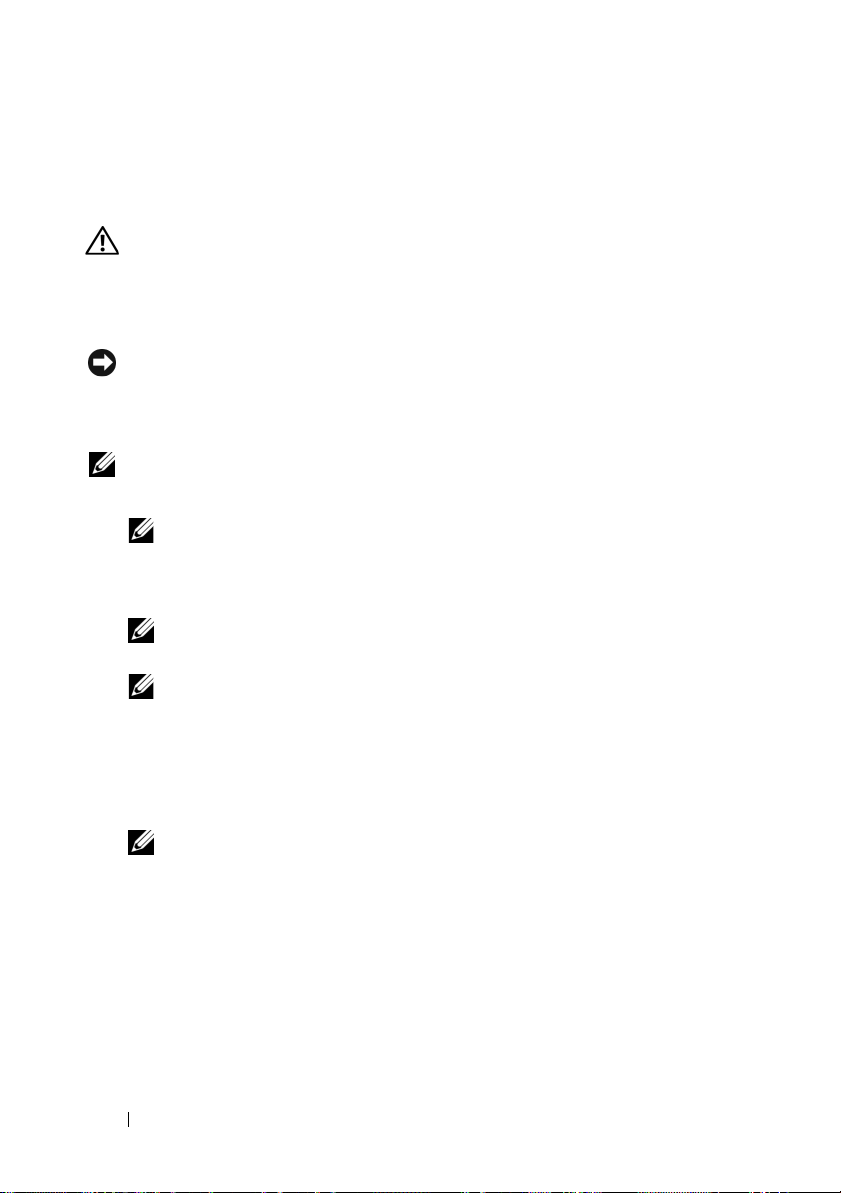
Visually inspect the controller and determine whether the dirty cache LED
on the memory module is turned on. See Figure 1. If the LED is turned on,
reinsert the controller into the system, replace the system cover, reconnect
the system to the electrical outlet, turn on the system, and repeat step 1.
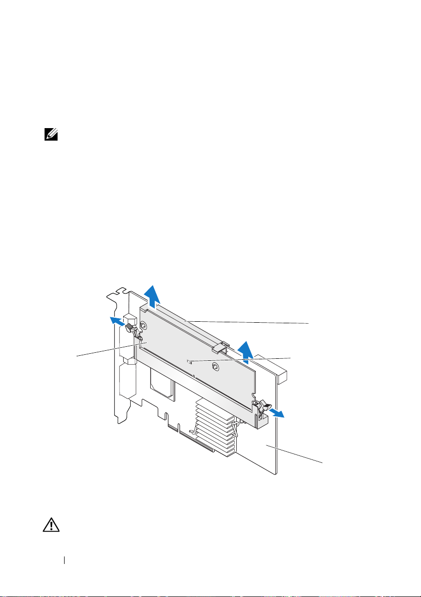
Figure 1. PERC x/E Adapter Dirty Cache LED Location
x
/E Adapter from the system. See the
for more information.
Dell PowerEdge Expandable
2
1
1 memory module 2 battery
3 dirty cache LED 4 PERC x/E Adapter
CAUTION: Running a system without the system cover installed may cause
damage due to improper cooling.
3
4
4 Removing and Installing the Battery and Battery Cable on PERC Controllers
Page 7
3
Remove the TBBU assembly from the PERC x/E Adapter by pressing down
on the tabs at each edge of the memory module connector and lifting the
TBBU off the adapter.
4
Disconnect the battery cable from the memory module.
NOTE: Do not exert excessive pressure on the connector on the memory
module while removing the memory module.
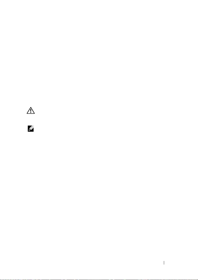
5
Detach the battery from the memory module by pressing out on the
battery clips inserted through the memory module and rotating the
battery off the memory module. See Figure 2.
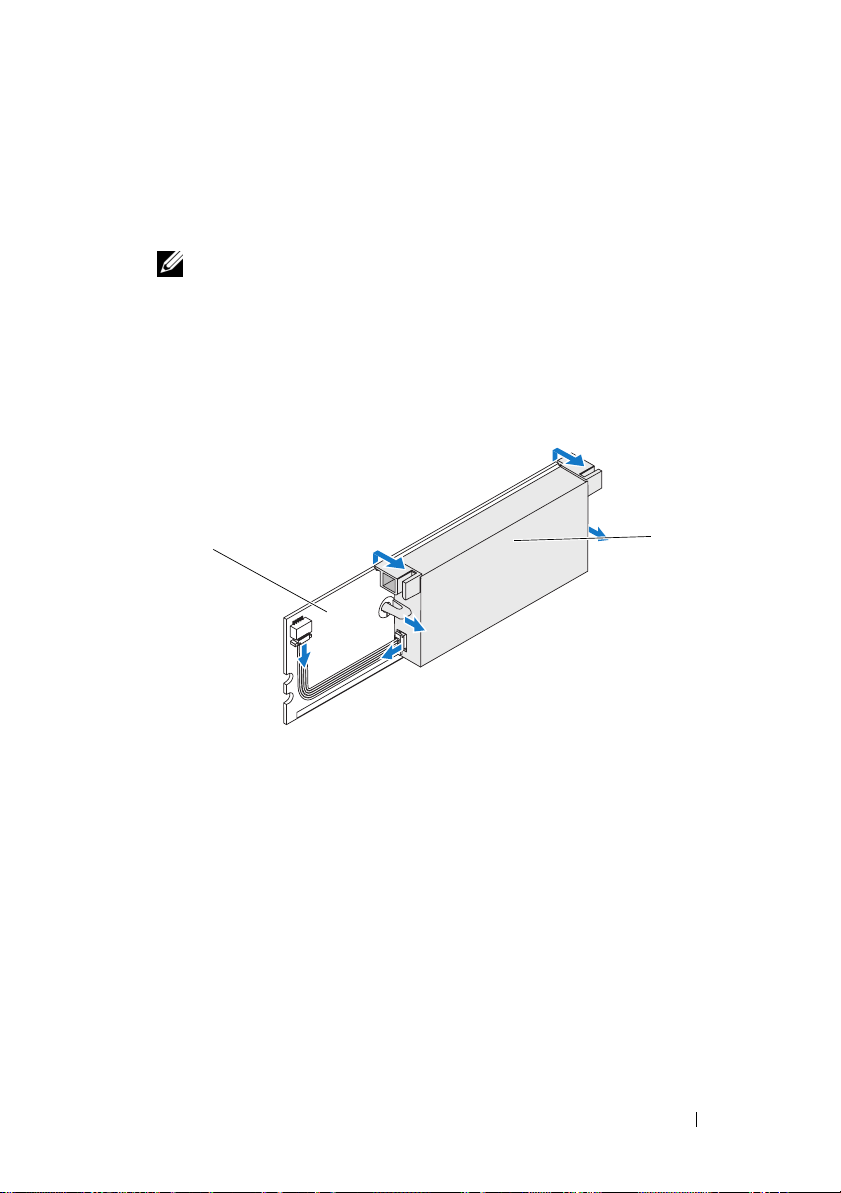
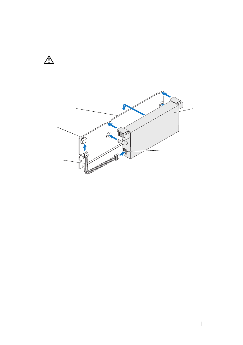
Figure 2. Removing the BBU
1
1 memory module 2 battery
2
Removing and Installing the Battery and Battery Cable on PERC Controllers 5
Page 8
Installing the New BBU and Battery Cable
This section describes the installation of the BBU and battery cable onto the DIMM
of a PERC
1
2
x
/E Adapter.
CAUTION: Only trained service technicians are authorized to remove the system
cover and access any of the components inside the system. Before performing any
procedure, see your Product Information Guide for complete information about
safety precautions, working inside the computer, and protecting against
electrostatic discharge
.
Unpack the BBU and follow all antistatic procedures.
NOTE: All work must be performed at an Electrostatic Discharge (ESD)-safe
workstation to meet the requirements of EIA-625—"Requirements For
Handling Electrostatic Discharge Sensitive Devices." All actions must be
performed following the IPC-A-610 latest revision ESD recommended
practices.
NOTE: Handle all sensitive components in a static-safe area. If possible,
use antistatic floor pads and work bench pads.
NOTE: When unpacking a static sensitive component from its shipping
carton, do not remove the component from the antistatic packing material
until you are ready to install the component. Just before unwrapping the
antistatic package, be sure to discharge static electricity from your body.
With the memory module removed from the controller, insert one end
of the battery cable (the red, white, yellow, and green wires) into the
connector on the memory module and the other end into the connector
on the battery.
NOTE: Do not exert excessive pressure on the connector on the memory
module while installing the memory module.
6 Removing and Installing the Battery and Battery Cable on PERC Controllers
Page 9
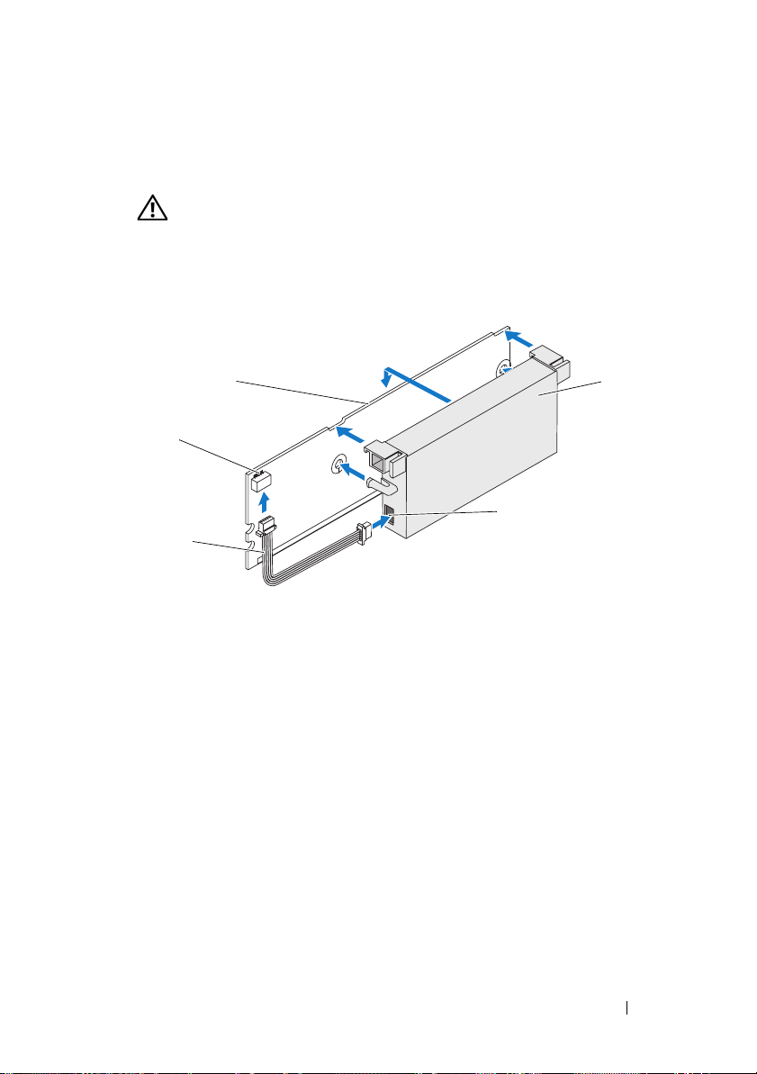
3
Place the top edge of the battery over the top edge of the memory module
so that the arms on the side of the battery fit into their sockets on the
memory module. See Figure 3.
CAUTION: Electrostatic discharge can damage sensitive components.
Always use proper antistatic protection when handling components.
Touching components without proper grounding can damage the equipment.
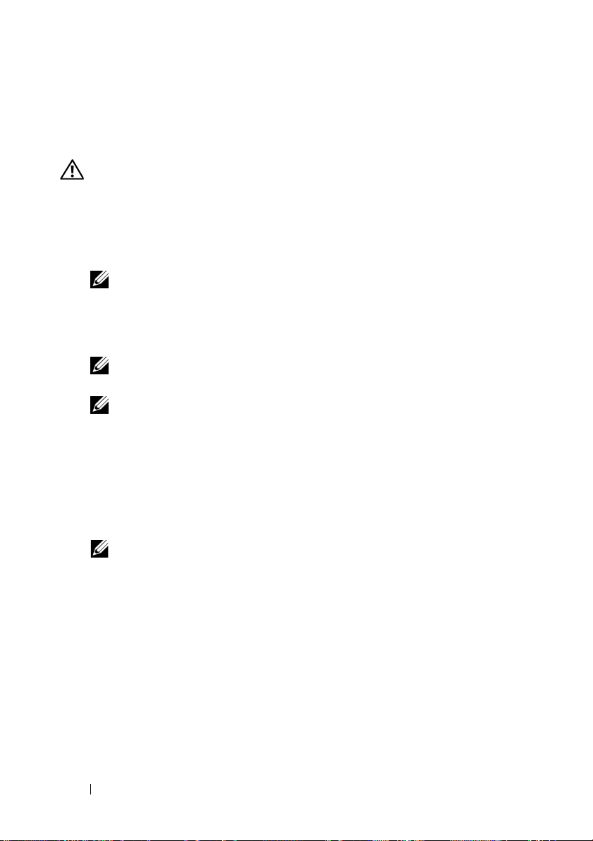
Figure 3. Installing the BBU and Battery Cable
1
2
5
3
1 memory module 2 connector on the memory module 3 battery cable
4 battery 5 connector on the battery
4
Place the PERC x/E Adapter on a flat, clean, and static–free surface.
5
Mount the memory module on the controller memory socket like a
4
standard DIMM. See the section "Installing the TBBU on a PERC x/E
Adapter" for more information.
The memory module is mounted flush with the board so that the memory
module is parallel to the board when installed.
6
Press the memory module firmly into the memory socket. As you press the
memory module into the socket, the BBU clicks into place, indicating that
the controller is firmly seated in the socket, and the arms on the socket fit
into the notches to hold the memory module securely.
Removing and Installing the Battery and Battery Cable on PERC Controllers 7
Page 10
Installing the TBBU on a PERC x/E Adapter
This section describes the procedure to install the memory module on a PERC
x
/E Adapter.
CAUTION: Only trained service technicians are authorized to remove the system
cover and access any of the components inside the system. Before performing any
procedure, see your Product Information Guide for complete information about
safety precautions, working inside the computer, and protecting against
electrostatic discharge.
NOTE: The TBBU on the PERC x/E Adapter consists of a dual in-line memory
module (DIMM) and a battery backup unit (BBU).
1
Remove the memory module in an antistatic environment.
NOTE: When unpacking a static-sensitive component from its shipping
carton, do not remove the component from the antistatic packing material
until you are ready to install the component. Just before unwrapping the
antistatic package, be sure to discharge static electricity from your body.
NOTE: Handle all sensitive components in a static-safe area. If possible,
use antistatic floor pads and work bench pads.
NOTE: Never touch the gold leads and do not bend the memory module.
2
Align the memory module so that the keyed edge of the memory module is
placed exactly on top of the physical divider on the memory socket of the
controller. This will avoid damage to the memory module.
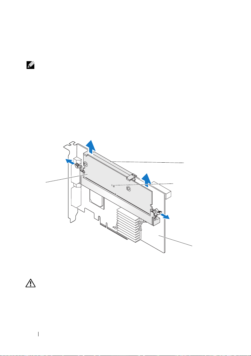
3
Insert the memory module on the memory socket of the controller and
apply a smooth, downward pressure on both ends or on the middle of the
memory module until the retention clips fall into the allotted slots on
either side of the memory module. Figure 4 displays the installation of
a memory module on a PERC
x
/E Adapter.
8 Removing and Installing the Battery and Battery Cable on PERC Controllers
Page 11

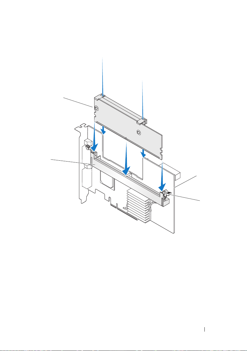
Figure 4. Installing a Dual In-line Memory Module
1
2
3
4
1 memory module 2 memory socket
3PERC x/E Adapter 4 retention clip
Removing and Installing the Battery and Battery Cable on PERC Controllers 9
Page 12
Removing the DIMM from a PERC x/i Controller
This section describes the procedure to remove the memory module from
aPERC
x
/i Adapter or PERCx/i Integrated controller installed in a system.
CAUTION: Only trained service technicians are authorized to remove the system
cover and access any of the components inside the system. Before performing any
procedure, see your Product Information Guide for complete information about
safety precautions, working inside the computer, and protecting against
electrostatic discharge.
NOTICE: Depending on the generation of your PERC card, the DIMM memory
module may not be removable. PERC 5/i cards include a removable DIMM module.
PERC 6/i cards have an integrated DIMM module which cannot be removed. Do not
attempt the following procedure on a PERC 6/i adapter or integrated controller card.
1
Perform a controlled shutdown of the system in which the PERC x/i
x
controller is installed and remove the PERC
See the
Guide
2
Remove the memory module by pressing down on the tabs at each edge
Dell PowerEdge Expandable RAID Controller x/i and x/E User’s
for more information.
CAUTION: Running a system without the system cover installed may cause
damage due to improper cooling.
/i controller from the system.
of the memory module connector and lifting the memory module off the
controller.
NOTE: Do not exert excessive pressure on the connector on the memory
module while removing the memory module.
NOTE: The location of the PERC x/i Integrated controller varies from system
to system. See the Hardware Owner’s Manual included with the system for
specific information on where the PERC x/i Integrated controller is located.
10 Removing and Installing the Battery and Battery Cable on PERC Controllers
Page 13
Disconnecting the BBU from a PERC x/i Controller
This section describes the procedure to disconnect the BBU on a PERC x/i
Adapter or PERC
CAUTION: Only trained service technicians are authorized to remove the system
cover and access any of the components inside the system. Before performing any
procedure, see your Product Information Guide for complete information about
safety precautions, working inside the computer, and protecting against
electrostatic discharge.
NOTE: PERC x/i Adapters installed in Dell Precision™ workstations or PowerEdge
SC servers do not have a BBU.
1
Perform a controlled shutdown of the system in which the PERC x/i
controller is installed.
2
Disconnect the system from the electrical outlet and remove the system
cover.
NOTE: See the Hardware Owner’s Manual included with the system for more
3
Locate the PERC x/i controller in the system and visually inspect the
controller to determine whether the dirty cache LED on the controller is
turned on. If the LED is turned on, replace the system cover, reconnect
the system to power, turn the system on and repeat steps 1 and 2.
CAUTION: Running a system without the system cover installed may cause
4
Locate the battery cable connection next to the memory module on the
controller, and disconnect the battery.
See the
on removing the BBU from the system chassis. The location of the TBBU
for the PERC
x
/i Integrated controller while it is installed in a system.
information on removing and reinstalling the system cover.
damage due to improper
Hardware Owner’s Manual
x
/i controller varies from system to system.
cooling.
included with the system for information
Removing and Installing the Battery and Battery Cable on PERC Controllers 11
Page 14
Installing the DIMM and BBU to a PERC x/i controller
This section describes the installation of the TBBU on a PERC x/i Adapter or
PERC
x
/i Integrated controller.
CAUTION: Only trained service technicians are authorized to remove the system
cover and access any of the components inside the system. Before performing any
procedure, see your Product Information Guide for complete information about
safety precautions, working inside the computer, and protecting against
electrostatic discharge.
NOTICE: Depending on the generation of your PERC card, the DIMM memory
module may not be removable. PERC 5/i cards include a removable DIMM module.
PERC 6/i cards have an integrated DIMM module which cannot be removed. Do not
attempt the following procedure on a PERC 6/i adapter or integrated controller card.
NOTE: Charge the PERC x battery before initial use to attain full functionality.
1
Unpack the DIMM and BBU and follow all antistatic procedures.
NOTE: All work must be performed at an Electrostatic Discharge (ESD)-safe
workstation to meet the requirements of EIA-625—"Requirements For Handling
Electrostatic Discharge Sensitive Devices." All actions must be performed
following the IPC-A-610 latest revision ESD recommended practices.
NOTE: Handle all sensitive components in a static-safe area. If possible,
use antistatic floor pads and work bench pads.
NOTE: When unpacking a static sensitive component from its shipping
carton, do not remove the component from the antistatic packing material
until you are ready to install the component. Just before unwrapping the
antistatic package, be sure to discharge static electricity from your body.
2
Locate the battery cable connection next to the memory module on the
controller, and connect the battery.
NOTE: Do not use excessive pressure on the connector on the memory
module while installing the memory module.
3
Align the memory module so that the keyed edge of the memory module
is placed exactly on top of the physical divider on the memory socket of the
controller. This will avoid damage to the memory module.
4
Insert the memory module on the memory socket of the controller and
apply a smooth, downward pressure on both ends or on the middle of the
memory module until the retention clips fall into the allotted slots on
either side of the memory module.
12 Removing and Installing the Battery and Battery Cable on PERC Controllers
Page 15

Dell™ PowerEdge™
可扩充
在
PERC
RAID
控制器
x
控制器上拆装电
池和电池电缆
Page 16

注、注意和警告
注:“注”表示可以帮助您更好地使用计算机的重要信息。
注意:“注意”表示可能会损坏硬件或导致数据丢失,并告诉您如何避免
此类问题。
警告:“警告”表示可能会出现导致财产损失、人身伤害甚至死亡的情况。
____________________
本说明文件中的信息如有更改,恕不另行通知。
© 2007 Dell Inc.
未经
Dell Inc.
本文中使用的商标:
本文件中述及的其它商标和产品名称是指拥有相应商标和名称的公司或其制造的产品。
Dell Inc.
型号
UCP-50 和 UCP-51
2007 年 11
版权所有,翻印必究。
书面许可,严禁以任何形式进行复制。
Dell、DELL
对本公司的商标和产品名称之外的其它商标和产品名称不拥有任何专有权。
月
P/N XR434
徽标、
Dell Precision 和 PowerEdge 是 Dell Inc.
修订版
A00
的商标。
Page 17
在
PERC
池电缆
控制器上拆装电池和电
本说明文件介绍如何在
上拆装电池、电池电缆和内存模块的信息。
•
有关
PERC x/E
息,请参阅第
•
有关
PERC x/i
Dell™ PowerEdge™
(其中
16
电池拆装过程的信息,请参阅第
表示第几代卡,如 5、6 等)电池拆装过程的信
x
页
可扩充
RAID
22
控制器
页
(PERC)
重要安全信息
警告: 任何需要拆卸系统护盖的安装均只限经过培训的维修技术人员进行。
有关安全预防措施、拆装计算机内部组件以及防止静电释放的完整信息,
请参阅随系统提供的 《产品信息指南》。
注:有关美国销售条款和条件、有限保修与退回规定、出口法规、软件许
可协议以及安全、环境和人机工程学说明、管制通告、循环利用信息等的完
整内容,请参阅随系统提供的《产品信息指南》。
在
控制器上拆装电池和电池电缆 15
PERC
Page 18
从
PERC x/E
本节介绍从安装在系统中的
注:
电池备用单元
1
对安装了
关闭,并从系统中卸下
适配器上卸下移动式电池备用单元
适配器上卸下
由一块双列直插式内存模块
适配器。有关详细信息,请参阅
PERC x/E
PERC x/E
PERC x/E
适配器上的
(BBU)
TBBU
构成。
适配器的系统以及任何连接的存储设备执行从容
PERC x/E
(TBBU)
TBBU
的过程。
(DIMM)
Dell PowerEdge Expandable RAID Controller x/i and x/E User’s Guide
(
Dell PowerEdge
2
通过外观来检查控制器,并确定内存模块上的已占用高速缓存
否亮起。请参阅图
可扩充
。如果
1
RAID
LED
控制器
x/i 和 x/E
用户指南)。
已亮起,则将控制器重新插入系统中,
装回系统护盖,将系统重新连接至电源插座,打开系统,然后重复
步骤 1。
和一个
LED
是
图
1. PERC x/E
1
警告:如果运行系统时未安装系统护盖,则可能会由于冷却不当而导致设
备损坏。
适配器已占用高速缓存
内存模块
1
已占用高速缓存
3
LED
LED
位置
2
4
电池
PERC x/E
3
适配器
2
4
16 在
控制器上拆装电池和电池电缆
PERC
Page 19
3
按下内存模块连接器两侧的卡舌并从适配器中提起内存模块
从
PERC x/E
4
从内存模块上断开电池电缆连接。
注:卸下内存模块时,请勿过度用力挤压内存模块上的连接器。
5
向外按压插入内存模块中的电池固定夹并旋转电池使之脱离内存
模块,从内存模块中卸下电池。请参阅图
图
卸下
2.
BBU
适配器中卸下
TBBU
部件。
。
2
TBBU
,
1
1
内存模块
电池
2
2
在
控制器上拆装电池和电池电缆 17
PERC
Page 20
安装新
本节介绍如何将
警告:只有经过培训的维修技术人员才有权卸下系统护盖并拆装系统内部
的任何组件。在执行任何过程之前,请参阅《产品信息指南》,获取有关安
全预防措施、拆装计算机内部组件以及防止静电释放的完整信息
打开
1
2
从控制器中卸下内存模块后,将电池电缆(红、白、黄和绿线)的一
和电池电缆
BBU
和电池电缆安装到
BBU
PERC x/E
适配器的
DIMM
。
包装,并遵循所有防静电过程。
BBU
注: 所有工作均必须在无静电释放
“处理静电释放敏感设备需求”的要求。执行所有操作时,必须遵循
IPC-A-610
注:请在无静电的工作区内处理所有的敏感组件。如果可能,
请使用防静电的地板垫和工作台垫。
注:打开包装箱取出静电敏感组件时,如果不准备安装此组件,请不
要将其从防静电包装材料中取出。打开防静电包装之前,应确保已导
去身上的静电。
最新版本
建议的方法。
ESD
的工作站上执行,以满足
(ESD)
端插入内存模块上的连接器中,将另一端插入电池上的连接器中。
注: 安装内存模块时,请勿过度用力挤压内存模块上的连接器。
中。
EIA-625 -
18 在
控制器上拆装电池和电池电缆
PERC
Page 21
3
将电池的顶部边缘放在内存模块的顶部边缘之上,以便电池一侧的支
臂可装入内存模块上的插槽中。请参阅图
警告:静电释放可能会损坏敏感组件。拿放组件时,应始终采用正确
的静电防护措施。在未正确接地的情况下触摸组件可能会损坏设备。
图
安装
3.
BBU
和电池电缆
。
3
1
2
3
内存模块
1
电池
4
4
将
PERC x/E
5
在控制器内存插槽中安装内存模块,如标准
请参阅“在
适配器放置在平坦、整洁、无静电的平面上。
PERC x/E
内存模块上的连接器
2
5
电池上的连接器
适配器上安装
TBBU
5
DIMM
”一节。
电池电缆
3
。有关详情,
4
安装内存模块,应使模块与系统板平齐,以便内存模块在安装后与系
统板平行。
6 将内存模块牢固地按入内存插槽中。随着将内存模块按入插槽中,
将卡入到位,这表示控制器已稳固地插入插槽中,同时插槽上的
BBU
支臂也插入槽口中,以确保牢固地把持内存模块。
在
控制器上拆装电池和电池电缆 19
PERC
Page 22
在
PERC x/E
本节介绍在
警告:只有经过培训的维修技术人员才有权卸下系统护盖并拆装系统内部
的任何组件。在执行任何过程之前,请参阅《产品信息指南》,获取有关安
全预防措施、拆装计算机内部组件以及防止静电释放的完整信息。
注:
电池备用单元
1
在防静电环境中卸下内存模块。
2
对齐内存模块,以便内存模块的键槽边缘正好放在控制器内存插槽上
适配器上安装
PERC x/E
PERC x/E
注: 打开包装箱取出静电敏感组件时,如果不准备安装此组件,请不
要将其从防静电包装材料中取出。打开防静电包装之前,应确保已导
去身上的静电。
注:请在无静电的工作区内处理所有的敏感组件。如果可能,
请使用防静电的地板垫和工作台垫。
注:请勿触摸镀金导线,也不要弯曲内存模块。
适配器上的
(BBU)
TBBU
适配器上安装内存模块的过程。
由一块双列直插式内存模块
TBBU
构成。
(DIMM)
的物理分隔架顶部。这样可以避免损坏内存模块。
3
在控制器的内存插槽上插入内存模块,并在内存模块两侧或中间施
加平稳向下的力,直至固定夹插入内存模块任一侧上分配的插槽中。
显示了如何在
图
4
PERC x/E
适配器上安装内存模块。
和一个
20 在
控制器上拆装电池和电池电缆
PERC
Page 23
图
安装双列直插式内存模块
4.
1
2
3
4
1
3
内存模块
PERC x/E
适配器
在
内存插槽
2
固定夹
4
控制器上拆装电池和电池电缆 21
PERC
Page 24
从
PERC x/i
本节介绍从安装在系统中的
控制器中卸下 内存模块
PERC x/i
适配器或集成的
PERC x/i
控制器上卸
下内存模块的过程。
警告:只有经过培训的维修技术人员才有权卸下系统护盖并拆装系统内部
的任何组件。在执行任何过程之前,请参阅《产品信息指南》,获取有关安
全预防措施、拆装计算机内部组件以及防止静电释放的完整信息。
注意:
PERC 5/i
成
DIMM
1
对安装了
PERC
Controller x/i and x/E User’s Guide
和
x/i
x/E
警告: 如果运行系统时未安装系统护盖,则可能会由于冷却不当而导
致设备损坏。
2
按下内存模块连接器两侧的卡舌并从控制器中提起内存模块,从而卸
内存模块可能不可拆卸,具体视您的
DIMM
卡包括一个可拆卸的
模块。请勿在
PERC x/i
控制器。有关详情,请参阅
x
/i
控制器的系统执行从容关闭,并从系统中卸下
DIMM
PERC 6/i
适配器或集成的控制器卡上尝试以下过程。
(
用户指南)。
模块。
PERC 6/i
Dell PowerEdge Expandable RAID
Dell PowerEdge
卡是第几代而定。
PERC
卡拥有一个不可拆卸的集
可扩充
RAID
下内存模块。
注: 卸下内存模块时,请勿过度用力挤压内存模块上的连接器。
注:
PERC x/i
制器位置的具体信息,请参阅系统附带的《硬件用户手册》。
集成控制器的位置随系统不同而异。有关
PERC x/i
控制器
集成控
22 在
控制器上拆装电池和电池电缆
PERC
Page 25
从
PERC x/i
本节介绍从安装在系统中的
连接的过程。
BBU
警告: 只有经过培训的维修技术人员才有权卸下系统护盖并拆装系统内部
的任何组件。在执行任何过程之前,请参阅《产品信息指南》,获取有关安
全预防措施、拆装计算机内部组件以及防止静电释放的完整信息。
注:安装在
器不配备
1
对安装了
2
断开系统与电源插座的连接,并卸下系统护盖。
3
找到系统中的
器上的已占用高速缓存
控制器中断开
Dell Precision™
。
BBU
PERC x/i
注:有关卸下和重新安装系统护盖的详情,请参阅随系统附带的
《硬件用户手册》。
控制器的系统执行从容关闭。
PERC x/i
连接
BBU
PERC x/i
工作站或
适配器或
PERC x/i
PowerEdge SC
集成控制器上断开
服务器中的
PERC x/i
控制器,通过外观来检查控制器,以确定控制
是否亮起。如果
LED
已亮起,则装回系
LED
统护盖,将系统重新连接至电源插座,打开系统,然后重复步骤
警告:如果运行系统时未安装系统护盖,则可能会由于冷却不当而导
致设备损坏。
4
找到控制器上内存模块旁边的电池电缆连接,然后断开电池连接。
有关从系统机箱中卸下
手册》。
PERC x/i
控制器的
的信息,请参阅随系统附带的《硬件用户
BBU
TBBU
的位置随系统不同而异。
1 和 2
适配
。
在
控制器上拆装电池和电池电缆 23
PERC
Page 26
将
DIMM 和 BBU
本节介绍在
警告:只有经过培训的维修技术人员才有权卸下系统护盖并拆装系统内部
1
2
3
PERC x/i
的任何组件。在执行任何过程之前,请参阅《产品信息指南》,获取有关安
全预防措施、拆装计算机内部组件以及防止静电释放的完整信息。
注意:
PERC 5/i
成
DIMM
注:首次使用
打开
DIMM 和 BBU
注: 所有工作均必须在无静电释放
“处理静电释放敏感设备需求”的要求。执行所有操作时,必须遵循
IPC-A-610
注:请在无静电的工作区内处理所有的敏感组件。如果可能,请使用
防静电的地板垫和工作台垫。
注:打开包装箱取出静电敏感组件时,如果不准备安装此组件,请不
要将其从防静电包装材料中取出。打开防静电包装之前,应确保已导
去身上的静电。
找到控制器上内存模块旁边的电池电缆连接,然后连接电池。
注: 安装内存模块时,请勿过度用力挤压内存模块上的连接器。
对齐内存模块,以便内存模块的键槽边缘正好放在控制器内存插槽上
安装到
PERC x/i
适配器或
内存模块可能不可拆卸,具体视您的
DIMM
卡包括一个可拆卸的
模块。请勿在
PERC x
PERC 6/i
电池之前,请先充电,以获得最佳性能。
控制器
PERC x/i
模块。
DIMM
适配器或集成的控制器卡上尝试以下过程。
的包装,并遵循所有防静电过程。
最新版本
建议的方法。
ESD
集成控制器上安装
PERC
PERC 6/i
(ESD)
卡拥有一个不可拆卸的集
的工作站上执行,以满足
TBBU
卡是第几代而定。
的物理分隔架顶部。这样可以避免损坏内存模块。
4
在控制器的内存插槽上插入内存模块,并在内存模块两侧或中间施加
平稳向下的力,直至固定夹插入内存模块任一侧上分配的插槽中。
的信息。
EIA-625 -
24 在
控制器上拆装电池和电池电缆
PERC
Page 27

Dell™ PowerEdge™ 可擴充
RAID 控制器 x
拆裝 PERC 控制器的
電池和電池電纜
Page 28

註、注意及警告
註:「註」會提供您更有效使用電腦的重要資訊。
注意:「注意」表示可能會損壞硬體或導致資料遺失,並告訴您如何避免
此類問題的發生。
警告:「警告」指出財產、人身可能遭受損害甚或造成死亡。
____________________
本文件中的資訊如有變更,恕不另行通知。
©2007DellInc.版權所有,翻印必究。
未經 Dell Inc. 的書面許可,不得以任何形式進行複製。
本文所用商標:Dell、DELL 標誌、Dell Precision 和 Powe rEd ge 是 Dell Inc. 的商標。
本文件所述及之其他商標或品牌名稱,均各自分屬其商標或產品名稱之申請者或擁
有者所擁有。Dell Inc. 對本公司之外的商標和產品名稱不擁有任何專有權。
型號 UCP-50 和 UCP-51
2007 年 11 月 P/N XR434 Rev. A00
Page 29

拆裝 PERC 控制器的電池和電池 電纜
本文件提供如何在
電池、電池電纜和記憶體模組的資訊。
•
請參閱第
(即 5、6 等)
請參閱第
•
Dell™ PowerEdge™
28
頁以瞭解
34
頁以瞭解
PERC x/E
PERC x/i
可擴充
RAID
控制器
(PERC)
電池拆裝程序,其中 x 表示第幾代的卡
電池拆裝程序
重要安全說明資訊
警告: 如果有任何安裝動作需要將系統機殼卸下,只能由專業的服務人員來
執行。請參閱系統隨附的產品資訊指南以獲得有關安全措施、在電腦內部工作
以及避免靜電釋放的完整資訊。
註:請參閱系統隨附的產品資訊指南以獲得有關美國銷售的條款與條件、
有限擔保與退貨、出口規定、軟體授權合約、安全說明、環境與人類工程的
指示、管制通告以及回收資訊。
上拆裝
拆裝 PERC 控制器的電池和電池電纜 27
Page 30
從 PERC x/E 配接卡上卸下移動式電池備援單元 (TBBU)
本節說明從系統中安裝的
註: PERC x/E 配接卡上的 TBBU 由一塊雙排直插式記憶體模組 (DIMM) 和一
個電池備援單元 (BBU) 構成。
1
正常關閉安裝有
然後從系統中卸下
控制器
x/i 和 x/E
2
目測檢查控制器,看記憶體模組上的已佔用快取
1
。如果
閱圖
殼,將系統重新連接至電源插座,開啟系統,然後重複步驟
圖 1. PERC x/E 配接卡已佔用快取記憶體 LED 位置
PERC x/E
PERC x/E
x/E
配接卡。請參閱《
配接卡上卸下
TBBU
的程序。
配接卡的系統以及任何連接的儲存裝置,
Dell PowerEdge
可擴充
使用者指南》以獲得更多資訊。
LED
是否亮起。請參
LED
已亮起,則將控制器重新插入系統中,裝回系統機
2
RAID
1
。
1
記憶體模組
1
已佔用快取記憶體 LED
3
警告:不安裝系統機殼而執行系統,可能會由於冷卻不當而損壞裝置。
電池
2
PERC x/E 配接卡
4
28 拆裝 PERC 控制器的電池和電池電纜
3
4
Page 31

3
按下記憶體模組控制器兩側的舌片並將
以從
PERC x/E
4
從記憶體模組上拔下電池電纜。
註:卸下記憶體模組時,請勿過度用力按壓記憶體模組上的連接器。
5
向外按壓插入記憶體模組中的電池固定夾並將電池旋出記憶體模組,
配接卡中卸下
TBBU
以從記憶體模組中卸下電池。請參閱圖
圖 2. 卸下 BBU
TBBU
總成。
2
。
提離配接卡,
1
1
記憶體模組
電池
2
2
拆裝 PERC 控制器的電池和電池電纜 29
Page 32

安裝新的 BBU 和電池電纜
本節說明如何將
警告:只有受過專業訓練的服務技術人員才能卸除系統機殼並拆裝任何內部
元件。在執行任何程序之前,請參閱產品資訊指南以獲得有關安全措施、
在電腦內部工作以及避免靜電釋放的完整資訊
開啟
1
註:
2
從控制器中卸下記憶體模組後,將電池電纜 (紅、白、黃和綠線) 的一
端插入記憶體模組上的連接器,將另一端插入電池上的連接器。
註: 安裝記憶體模組時,請勿過度用力按壓記憶體模組上的連接器。
BBU
和電池電纜安裝到
PERC x/E
配接卡的
DIMM
。
BBU
包裝,並遵循所有防靜電程序。
所有工作均必須在無靜電釋放 (ESD) 的工作站上執行 , 以滿 足 EIA-625 -
「處理靜電釋放敏感裝置需求」的要求。執行所有操作時,必須遵循
IPC-A-610 最新版本 ESD 建議的方法。
註:請在無靜電的工作區域處理所有的敏感元件。如有可能,請使用
防靜電地板墊和工作檯墊。
註:打開對靜電敏感之元件的運送紙箱時,在您已準備好將它安裝到
電腦內之前,請勿將元件從防靜電的包裝材料中取出。打開抗靜電包
裝前,請確定已釋放出您體內的靜電。
中。
30 拆裝 PERC 控制器的電池和電池電纜
Page 33

3
將電池的頂邊放在記憶體模組的頂邊之上,以便電池一側的支臂可裝
入記憶體模組上的插槽中。請參閱圖
警告:靜電釋放可能會損壞敏感元件。處理元件時,請務必遵循正確
的靜電防護措施。在未正確接地的情況下觸摸元件可能會損壞設備。
圖 3. 安裝 BBU 和電池電纜
3
。
2
3
記憶體模組
1
電池
4
4將 x/E
1
5
記憶體模組上的連接器
2
電池上的連接器
5
3
配接卡放置在平坦、整潔、無靜電的平面上。
電池電纜
4
5 在控制器記憶體插槽中安裝記憶體模組,如標準 DIMM。請參閱
「在
PERC x/E
配接卡上安裝
TBBU」
以獲得更多資訊。
安裝記憶體模組,應使模組與主機板平齊,以便記憶體模組在安裝時
與主機板平行。
6
將記憶體模組穩固地按入記憶體插槽中。將記憶體模組按入插槽時,
BBU
會卡入到位,這表示控制器已穩固地插入插槽中,同時插槽上的
支臂也插入槽口中,以確保固定記憶體模組。
拆裝 PERC 控制器的電池和電池電纜 31
Page 34

在 PERC x/E 配接卡上安裝 TBBU
本節說明在
警告:只有受過專業訓練的服務技術人員才能卸除系統機殼並拆裝任何內部
1
2
3
PERC x/E
元件。在執行任何程序之前,請參閱產品資訊指南以獲得有關安全措施、
在電腦內部工作以及避免靜電釋放的完整資訊。
配接卡上安裝記憶體模組的程序。
註:PERC x/E 配接卡上的 TBBU 由一塊雙排直插式記憶體模組 (DIMM)
和一個電池備援單元 (BBU) 構成。
在防靜電環境中卸下記憶體模組。
註: 打開對靜電敏感之元件的運送紙箱時,在您已準備好將它安裝到
電腦內之前,請勿將元件從防靜電的包裝材料中取出。打開抗靜電包
裝前,請確定已釋放出您體內的靜電。
註:請在無靜電的工作區域處理所有的敏感元件。如有可能,請使用
防靜電地板墊和工作檯墊。
註:請勿觸摸鍍金導線,也不要彎曲記憶體模組。
對齊記憶體模組,以便記憶體模組的鍵槽邊緣正好放在控制器記憶體
插槽上物理隔板的頂部。這樣可以避免損壞記憶體模組。
在控制器的記憶體插槽上插入記憶體模組,並在記憶體模組兩側或中
間平穩向下按壓,直至固定夾插入記憶體模組任一側的指定插槽中。
4
顯示了如何在
圖
PERC x/E
配接卡上安裝記憶體模組。
32 拆裝 PERC 控制器的電池和電池電纜
Page 35

圖 4. 安裝雙排直插式記憶體模組
1
2
3
4
記憶體模組
1
PERC x/E 配接卡
3
記憶體插槽
2
固定夾
4
拆裝 PERC 控制器的電池和電池電纜 33
Page 36

從 PERC x/i 控制器中卸下 DIMM
本節說明從系統中安裝的
記憶體模組的程序。
警告:只有受過專業訓練的服務技術人員才能卸除系統機殼並拆裝任何內部
元件。在執行任何程序之前,請參閱產品資訊指南以獲得有關安全措施、
在電腦內部工作以及避免靜電釋放的完整資訊。
注意:根據您是第幾代的 PERC 卡,DIMM 記憶體模組或許可能無法卸下。
PERC 5/i 卡包括可卸下的 DIMM 模組。PERC 6/i 卡為整合式 DIMM 模組,將無
法卸下。在 PERC 6/i 配接卡或整合式控制器卡上,請勿嘗試以下程序。
1
正常關閉安裝有
控制器。請參閱《
指南》以獲得更多資訊。
警告: 不安裝系統機殼而執行系統,可能會由於冷卻不當而損壞裝置。
2 按下記憶體模組連接器兩邊的舌片並從控制器中提起記憶體模組,
以卸下記憶體模組。
註: 卸下記憶體模組時,請勿過度用力按壓記憶體模組上的連接器。
註:PERC x/i 整合式控制器的位置因系統而異。請參閱系統隨附的
《硬體使用者手冊》以獲得有關 PERC x/i 整合式控制器位置的具體資訊。
PERC x/i
PERC x/i
控制器的系統,然後從系統中卸下
Dell PowerEdge
配接卡或整合式
可擴充
RAID
PERCx/i
控制器
x/i 和 x/E
控制器上卸下
PERC x/i
使用者
34 拆裝 PERC 控制器的電池和電池電纜
Page 37

從 PERC x/i 控制器中卸下 BBU
本節說明從系統中安裝的
BBU
卸下
1
2
3
的程序。
警告: 只有受過專業訓練的服務技術人員才能卸除系統機殼並拆裝任何內部
元件。在執行任何程序之前,請參閱產品資訊指南以獲得有關安全措施、
在電腦內部工作以及避免靜電釋放的完整資訊。
註:Dell Precision™ 工作站或 PowerEdge SC 伺服器中安裝的 PERC x/i 配接卡
沒有 BBU。
正常關閉安裝有
從電源插座拔下系統的電源插頭,然後卸下系統機殼。
註:請參閱系統隨附的《硬體使用者手冊》以獲得有關卸下和重新安
裝系統機殼的更多資訊。
找到系統中的
亮起。如果
LED
插座,開啟系統,然後重複步驟
警告:不安裝系統機殼而執行系統,可能會由於冷卻不當而損壞裝置。
4
找到控制器上記憶體模組旁邊的電池電纜連接,然後斷開電池連接。
請參閱系統隨附的《硬體使用者手冊》以獲得有關從系統機箱中卸下
BBU
的資訊。
PERC x/i
PERC x/i
PERC x/i
配接卡或整合式
PERC x/i
整合控制器上
控制器的系統。
控制器,觀察控制器上的已佔用快取
已亮起,則裝回系統機殼,將系統重新連接至電源
1 和 2
。
PERC x/i
整合式控制器的
TBBU
位置因系統而異。
LED
是否
拆裝 PERC 控制器的電池和電池電纜 35
Page 38

將 DIMM 和 BBU 安裝至 PERC x/i 控制器
本節說明在
警告:只有受過專業訓練的服務技術人員才能卸除系統機殼並拆裝任何內部
1
2
3
4
PERC x/i
元件。在執行任何程序之前,請參閱產品資訊指南以獲得有關安全措施、
在電腦內部工作以及避免靜電釋放的完整資訊。
配接卡或
PERC x/i
整合式控制器上安裝
TBBU
注意:根據您是第幾代的 PERC 卡,DIMM 記憶體模組或許可能無法卸下。
PERC 5/i 卡包括可卸下的 DIMM 模組。PERC 6/i 卡為整合式 DIMM 模組,將無
法卸下。在 PERC 6/i 配接卡或整合式控制器卡上,請勿嘗試以下程序。
註:第一次使用 PERC x 電池之前,請先充電,以獲得最佳效能。
開啟
DIMM 和 BBU
註:
所有工作均必須在無靜電釋放 (ESD) 的工作站上執行 , 以滿 足 EIA-625 -
「處理靜電釋放敏感裝置需求」的要求。執行所有操作時,必須遵循
IPC-A-610 最新版本 ESD 建議的方法。
註:請在無靜電的工作區域處理所有的敏感元件。如有可能,請使用
防靜電地板墊和工作檯墊。
註:打開對靜電敏感之元件的運送紙箱時,在您已準備好將它安裝到
電腦內之前,請勿將元件從防靜電的包裝材料中取出。打開抗靜電包
裝前,請確定已釋放出您體內的靜電。
包裝,並遵循所有防靜電程序。
找到控制器上記憶體模組旁邊的電池電纜連接,然後連接電池。
註: 安裝記憶體模組時,請勿過度用力按壓記憶體模組上的連接器。
對齊記憶體模組,以便記憶體模組的鍵槽邊緣正好放在控制器記憶體
插槽上物理隔板的頂部。這樣可以避免損壞記憶體模組。
在控制器的記憶體插槽上插入記憶體模組,並在記憶體模組兩側或中
間平穩向下按壓,直至固定夾插入記憶體模組任一側的指定插槽中。
的資訊。
36 拆裝 PERC 控制器的電池和電池電纜
Page 39

Contrôleurs Dell™ PERC x
Retrait et installation de la
batterie et de son câble sur
les contrôleurs PERC
Page 40

Remarques, avis et précautions
REMARQUE : Une REMARQUE indique des informations importantes qui peuvent
vous aider à mieux utiliser votre ordinateur.
AVIS : Un AVIS vous avertit d'un dommage ou d'une perte de données potentiels
et vous indique comment éviter ce problème.
PRÉCAUTION : Une PRÉCAUTION indique un risque potentiel d'endommagement
du matériel, de blessure corporelle ou de mort.
____________________
Les informations contenues dans ce document peuvent être modifiées sans préavis.
© 2007 Dell Inc. Tous droits réservés.
La reproduction de ce document de quelque manière que ce soit sans l'autorisation écrite de Dell Inc.
est strictement interdite.
Marques utilisées dans ce document : Dell, le logo DELL, Dell Precision et PowerEdge sont
des marques de Dell Inc.
D'autres marques et noms de marques peuvent être utilisés dans ce document pour faire référence aux
entités se réclamant de ces marques et de ces noms ou à leurs produits. Dell Inc. dénie tout intérêt
propriétaire vis-à-vis des marques et des noms de marque autres que les siens.
Modèles UCP-50 et UCP-51
Novembre 2007 N/P XR434 Rév. A00
Page 41

Retrait et installation de la batterie et de son câble sur les contrôleurs PERC
Ce document contient des informations concernant l'installation et le retrait
de la batterie, de son câble et de la barrette de mémoire sur un contrôleur Dell™
PERC (PowerEdge™ Expandable RAID Controller).
• Voir page 40 pour obtenir les instructions de retrait et d'installation de
la batterie sur les contrôleurs PERC
de la carte (5, 6, etc.).
• Voir page 47 pour obtenir les instructions de retrait et d'installation
de la batterie sur les contrôleurs PERC
Informations importantes concernant la sécurité
PRÉCAUTION : Toute procédure d'installation nécessitant le retrait du capot du
système doit être effectuée uniquement par des techniciens de maintenance qualifiés.
Consultez le document Product Information Guide (Guide d'informations sur le produit)
fourni avec le système pour obtenir des informations détaillées sur les consignes de
sécurité, les interventions dans l'ordinateur et la protection contre les décharges
électrostatiques.
REMARQUE : Reportez-vous au document Product Information Guide
(Guide d'informations sur le produit) fourni avec le système pour obtenir des
informations complètes sur les sujets suivants : termes et conditions de vente
(États-Unis uniquement), garanties limitées et règles de retour, règlementations
pour l'exportation, contrat de licence des logiciels, consignes de sécurité,
instructions relatives à l'environnement et à l'ergonomie, notes relatives
à la réglementation et informations concernant le recyclage.
x
/E, où x représente la génération
x
/i.
Retrait et installation de la batterie et de son câble sur les contrôleurs PERC 39
Page 42

Retrait de la TBBU d'une carte PERC x/E
Cette section indique comment retirer la TBBU (Transportable Battery Backup
Unit, unité de batterie de sauvegarde transportable) d'une carte PERC
installée dans un système.
x
/E
REMARQUE :
DIMM et d'une BBU (Battery Backup Unit, unité de batterie de sauvegarde).
1
Arrêtez (à l'aide de l'option appropriée du système d'exploitation) le système
contenant la carte PERC
connectées, puis retirez la carte PERC
d'informations, consultez le document
Controller x/i and x/E User's Guide
La TBBU connectée à une carte PERC x/E se compose d'une barrette
x
/E, ainsi que toutes les baies de stockage
x
/E du système. Pour plus
Dell PowerEdge Expandable RAID
(Contrôleur Dell PERC x/i et x/E -
Guide d'utilisation).
2
Inspectez la carte et vérifiez si le voyant de la barrette de mémoire
indiquant que la mémoire cache contient des fichiers en attente d'écriture
(“dirty cache”) est allumé. Voir figure 1. Si le voyant est allumé, réinsérez
la carte dans le système, remettez le capot en place, rebranchez le système,
mettez-le sous tension puis reprenez à l'étape 1.
Figure 1. Emplacement du voyant “dirty cache” sur l'adaptateur PERC x/E
2
1
3
4
1 Barrette de mémoire 2 Batterie
3 Voyant de la mémoire cache 4 Carte PERC x/E
40 Retrait et installation de la batterie et de son câble sur les contrôleurs PERC
Page 43

PRÉCAUTION : Vous ne devez pas faire fonctionner l'ordinateur lorsque le capot
est retiré. Cela risquerait de provoquer une surchauffe et d'endommager le
système.
3
Pour retirer la TBBU de la carte PERCx/E, appuyez sur les pattes situées
à chaque extrémité du connecteur de la barrette de mémoire et soulevez
la TBBU.
4
Déconnectez le câble de la batterie de la barrette de mémoire.
REMARQUE : N'appuyez pas trop fort sur le connecteur lorsque vous retirez
la barrette de mémoire.
5
Pour retirer la batterie de la barrette de mémoire, appuyez sur les clips
de fixation et faites pivoter la batterie. Voir figure 2.
Figure 2. Retrait de la BBU
1
1 Barrette de mémoire 2 Batterie
Retrait et installation de la batterie et de son câble sur les contrôleurs PERC 41
2
Page 44

Installation d'une nouvelle BBU et du câble de la batterie
Cette section décrit l'installation d'une BBU et du câble de la batterie sur la barrette
DIMM d'une carte PERC
PRÉCAUTION : Seuls les techniciens de maintenance qualifiés sont habilités
à retirer le capot du système pour accéder aux composants internes. Avant de
commencer toute intervention, consultez le document Product Information Guide
(Guide d'informations sur le produit) pour obtenir des informations complètes sur
les consignes de sécurité, les interventions dans l'ordinateur et la protection contre
les décharges électrostatiques
1
Déballez la BBU et suivez toutes les procédures requises pour éliminer
l'électricité statique.
REMARQUE : La conformité à la norme EIA-625 relative à la manipulation
des appareils sensibles aux décharges électrostatiques exige que le poste
de travail soit protégé contre les décharges électrostatiques (ESD). Toutes les
procédures doivent être conformes aux recommandations les plus récentes
de la norme IPC-A-610 concernant les décharges électrostatiques.
REMARQUE : Manipulez les composants sensibles dans une zone protégée
contre l'électricité statique. Dans la mesure du possible, utilisez des tapis
de sol et des revêtements antistatiques pour le plan de travail.
REMARQUE : Lorsque vous sortez un composant sensible à l'électricité
statique de son carton, ne le retirez de l'emballage antistatique que si vous
êtes prêt à l'installer. Juste avant de retirer l'emballage antistatique,
déchargez bien l'électricité statique accumulée dans votre organisme.
2
Une fois la barrette de mémoire retirée de la carte, insérez l'une des
extrémités du câble de la batterie (fils rouge, blanc, jaune et vert) dans
le connecteur de la barrette et l'autre extrémité dans le connecteur de
la batterie.
x
/E.
.
REMARQUE : N'appuyez pas trop fort sur le connecteur lorsque vous
installez la barrette de mémoire.
3
Placez le bord supérieur de la batterie par-dessus celui de la barrette de
mémoire, de sorte que les pattes latérales de la batterie s'emboîtent dans
les trous correspondants situés sur la barrette de mémoire. Voir figure 3.
PRÉCAUTION : Les décharges électrostatiques peuvent endommager les
composants sensibles. Utilisez toujours une protection antistatique lorsque
vous manipulez des composants. Si vous touchez des composants sans être
relié à la terre, vous risquez de les endommager.
42 Retrait et installation de la batterie et de son câble sur les contrôleurs PERC
Page 45

Figure 3. Installation d'une nouvelle BBU et du câble de la batterie
1
2
5
3
1 Barrette de
mémoire
4 Batterie 5 Connecteur sur la batterie
4
Placez la carte PERCx/E sur une surface propre et stable sans électricité
2 Connecteur sur la barrette
de mémoire
3 Câble de la batterie
statique.
5
Montez la barrette de mémoire sur le logement correspondant du
contrôleur, de la même façon qu'une barrette DIMM standard. Pour plus
d'informations, voir “Installation de la TBBU sur une carte PERC x/E”.
La barrette de mémoire étant montée au même niveau que la carte,
elle est parallèle à cette dernière une fois installée.
6
Appuyez fermement sur la barrette pour l'enclencher dans le support
de mémoire. Au cours de cette opération, vous devez entendre un déclic
indiquant que la BBU est en place et que le contrôleur est correctement
emboîté. Les pattes du support s'enclenchent dans les trous
correspondants et maintiennent la barrette de mémoire en place.
4
Retrait et installation de la batterie et de son câble sur les contrôleurs PERC 43
Page 46

Installation de la TBBU sur une carte PERC x/E
Cette section décrit l'installation de la barrette de mémoire sur une carte
PERC
x
/E.
PRÉCAUTION : Seuls les techniciens de maintenance qualifiés sont habilités
à retirer le capot du système pour accéder aux composants internes. Avant de
commencer toute intervention, consultez le document Product Information Guide
(Guide d'informations sur le produit) pour obtenir des informations complètes sur
les consignes de sécurité, les interventions dans l'ordinateur et la protection contre
les décharges électrostatiques.
REMARQUE : La TBBU connectée à une carte PERC x/E se compose
d'une barrette DIMM et d'une BBU.
1
Retirez la barrette de mémoire dans un environnement antistatique.
REMARQUE : Lorsque vous sortez un composant sensible à l'électricité
statique de son carton, ne le retirez de l'emballage antistatique que si
vous êtes prêt à l'installer. Juste avant de retirer l'emballage antistatique,
déchargez bien l'électricité statique accumulée dans votre organisme.
REMARQUE : Manipulez les composants sensibles dans une zone protégée
contre l'électricité statique. Dans la mesure du possible, utilisez des tapis
de sol et des revêtements antistatiques pour le plan de travail.
REMARQUE : Ne touchez jamais les fils dorés et ne pliez pas la barrette
de mémoire.
2
Positionnez la barrette de mémoire de sorte que son encoche soit placée
exactement au-dessus du séparateur situé sur le support mémoire du
contrôleur. Cela évite d'endommager la barrette.
3
Insérez la barrette dans le support mémoire du contrôleur et enfoncez-la
en appuyant sur les deux extrémités ou sur le milieu de la barrette, jusqu'à
ce que les clips de fixation s'enclenchent dans les encoches situées des
deux côtés de la barrette. La figure 4 montre comment installer une
barrette de mémoire sur une carte PERC
x
/E.
44 Retrait et installation de la batterie et de son câble sur les contrôleurs PERC
Page 47

Figure 4. Installation d'une barrette DIMM
1
2
3
4
1 Barrette de mémoire 2 Support mémoire
3 Carte PERC x/E 4 Clip de fixation
Retrait et installation de la batterie et de son câble sur les contrôleurs PERC 45
Page 48

Retrait de la barrette DIMM d'un contrôleur PERC x/i
Cette section indique comment retirer la barrette de mémoire d'une
carte PERC
PRÉCAUTION : Seuls les techniciens de maintenance qualifiés sont habilités
1
2
x
/i ou d'un contrôleur PERCx/i intégré installé dans un système.
à retirer le capot du système pour accéder aux composants internes. Avant de
commencer toute intervention, consultez le document Product Information Guide
(Guide d'informations sur le produit) pour obtenir des informations complètes sur
les consignes de sécurité, les interventions dans l'ordinateur et la protection contre
les décharges électrostatiques.
AVIS : Selon la génération de votre carte PERC, il est possible que la barrette
DIMM ne soit pas amovible. Les cartes PERC 5/i incluent une barrette DIMM
amovible. Les cartes PERC 6/i sont équipées d'une barrette DIMM intégrée qui ne
peut pas être retirée. N'essayez pas d'appliquer la procédure suivante à une carte
PERC 6/i ou à une carte contrôleur intégrée.
Arrêtez (à l'aide de l'option appropriée du système d'exploitation) le système
contenant le contrôleur PERC
d'informations, consultez le document
Controller x/i and x/E User's Guide
x
/i et retirez ce dernier du système. Pour plus
Dell PowerEdge Expandable RAID
(Contrôleur Dell PERC x/i et x/E -
Guide d'utilisation).
PRÉCAUTION : Vous ne devez pas faire fonctionner l'ordinateur lorsque le
capot est retiré. Cela risquerait de provoquer une surchauffe et d'endommager
le système.
Pour retirer la barrette de mémoire, appuyez sur les pattes situées à chaque
extrémité du connecteur correspondant, puis soulevez la barrette pour la
retirer du contrôleur.
REMARQUE : N'appuyez pas trop fort sur le connecteur lorsque vous retirez
la barrette de mémoire.
REMARQUE : L'emplacement du contrôleur PERC x/i intégré varie
d'un système à l'autre. Consultez le document Hardware Owner's Manual
(Manuel du propriétaire) fourni avec le système pour identifier cet
emplacement.
46 Retrait et installation de la batterie et de son câble sur les contrôleurs PERC
Page 49

Retrait de la BBU d'un contrôleur PERC x/i
Cette section indique comment retirer la BBU d'une carte PERCx/i ou d'un
contrôleur PERC
PRÉCAUTION : Seuls les techniciens de maintenance qualifiés sont habilités
à retirer le capot du système pour accéder aux composants internes. Avant de
commencer toute intervention, consultez le document Product Information Guide
(Guide d'informations sur le produit) pour obtenir des informations complètes sur
les consignes de sécurité, les interventions dans l'ordinateur et la protection contre
les décharges électrostatiques.
REMARQUE : Les cartes PERC x/i installées dans des stations de travail Dell
Precision™ ou des serveurs PowerEdge SC ne sont pas équipées d'une BBU.
1
Arrêtez (à l'aide de l'option appropriée du système d'exploitation) le
système contenant le contrôleur PERC
2
Débranchez le système de la prise secteur, puis retirez le capot.
REMARQUE : Consultez le document Hardware Owner's Manual (Manuel
3
Recherchez le contrôleur PERCx/i installé sur le système et inspectez-le
pour vérifier si le voyant indiquant que la mémoire cache contient des
fichiers en attente d'écriture (“dirty cache”) est allumé. Si tel est le cas,
remettez le capot en place, rebranchez le système sur le secteur, mettez-le
sous tension puis recommencez les étapes 1 et 2.
x
/i intégré installé dans un système.
x
/i.
du propriétaire) fourni avec le système pour plus d'informations sur le retrait
et la réinstallation du capot.
PRÉCAUTION : L'utilisation du système sans son capot risque de provoquer
des dommages dus à un refroidissement insuffisant.
4
Recherchez le connecteur du câble de la batterie (près de la barrette
de mémoire du contrôleur), puis déconnectez la batterie.
Consultez le document
Hardware Owner's Manual
(Manuel du
propriétaire) fourni avec le système pour savoir comment retirer la BBU du
châssis du système. L'emplacement de la TBBU du contrôleur PERC
x
/i
varie d'un système à l'autre.
Retrait et installation de la batterie et de son câble sur les contrôleurs PERC 47
Page 50

Installation de la barrette DIMM et de la BBU sur un contrôleur PERC x/i
Cette section décrit l'installation de la TBBU sur une carte PERCx/i ou un
contrôleur PERC
PRÉCAUTION : Seuls les techniciens de maintenance qualifiés sont habilités
à retirer le capot du système pour accéder aux composants internes. Avant de
commencer toute intervention, consultez le document Product Information Guide
(Guide d'informations sur le produit) pour obtenir des informations complètes sur
les consignes de sécurité, les interventions dans l'ordinateur et la protection contre
les décharges électrostatiques.
AVIS : Selon la génération de votre carte PERC, il est possible que la barrette
DIMM ne soit pas amovible. Les cartes PERC 5/i incluent une barrette DIMM
amovible. Les cartes PERC 6/i sont équipées d'une barrette DIMM intégrée qui ne
peut pas être retirée. N'essayez pas d'appliquer la procédure suivante à une carte
PERC 6/i ou à une carte contrôleur intégrée.
REMARQUE : Pour optimiser le fonctionnement de la carte PERC x, chargez
sa batterie avant de l'utiliser.
1
Déballez la barrette DIMM et la BBU ; suivez toutes les procédures
requises pour éliminer l'électricité statique.
REMARQUE : La conformité à la norme EIA-625 relative à la manipulation
x
/i intégré.
des appareils sensibles aux décharges électrostatiques exige que le poste
de travail soit protégé contre les décharges électrostatiques (ESD). Toutes
les procédures doivent être conformes aux recommandations les plus récentes
de la norme IPC-A-610 concernant les décharges électrostatiques.
REMARQUE : Manipulez les composants sensibles dans une zone protégée
contre l'électricité statique. Dans la mesure du possible, utilisez des tapis
de sol et des revêtements antistatiques pour le plan de travail.
REMARQUE : Lorsque vous sortez un composant sensible à l'électricité
statique de son carton, ne le retirez de l'emballage antistatique que si vous
êtes prêt à l'installer. Juste avant de retirer l'emballage antistatique,
déchargez bien l'électricité statique accumulée dans votre organisme.
48 Retrait et installation de la batterie et de son câble sur les contrôleurs PERC
Page 51

2
Recherchez le connecteur du câble de la batterie (près de la barrette
de mémoire du contrôleur), puis connectez la batterie.
REMARQUE : N'appuyez pas trop fort sur le connecteur lorsque vous
installez la barrette de mémoire.
3
Positionnez la barrette de mémoire de sorte que son encoche soit placée
exactement au-dessus du séparateur situé sur le support mémoire du
contrôleur. Cela évite d'endommager la barrette.
4
Insérez la barrette dans le support mémoire du contrôleur et enfoncez-la
en appuyant sur les deux extrémités ou sur le milieu de la barrette, jusqu'à
ce que les clips de fixation s'enclenchent dans les encoches situées des
deux côtés de la barrette.
Retrait et installation de la batterie et de son câble sur les contrôleurs PERC 49
Page 52

50 Retrait et installation de la batterie et de son câble sur les contrôleurs PERC
Page 53

Dell™ PowerEdge™
Expandable RAID Controller x
Entfernen und Installieren
des Akkus und des
Akkukabels bei PERC-
Controllern
Page 54

Anmerkungen, Hinweise und Vorsichtshinweise
ANMERKUNG: Eine ANMERKUNG macht auf wichtige Informationen aufmerksam,
die die Arbeit mit dem Computer erleichtern.
HINWEIS: Ein HINWEIS warnt vor möglichen Beschädigungen der Hardware oder
vor Datenverlust und zeigt auf, wie derartige Probleme vermieden werden können.
VORSICHT: Hiermit werden Sie auf eine potentiell gefährliche Situation
hingewiesen, die zu Sachschäden, Verletzungen oder zum Tod führen könnte.
____________________
Irrtümer und technische Änderungen vorbehalten.
© 2007 Dell Inc. Alle Rechte vorbehalten.
Die Vervielfältigung oder Wiedergabe in jeglicher Weise ohne vorherige schriftliche Genehmigung
von Dell Inc. sind strengstens untersagt.
In diesem Text verwendete Marken: Dell, das DELL Logo, Dell Precision und PowerEdge
sind Marken von Dell Inc.
Alle anderen in dieser Dokumentation genannten Marken und Handelsbezeichnungen sind Eigentum
der jeweiligen Hersteller und Firmen. Dell Inc. erhebt keinen Anspruch auf Besitzrechte an Marken
und Handelsbezeichnungen mit Ausnahme der eigenen.
Modelle UCP-50 und UCP-51
November 2007 Teilenr. XR434 Rev. A00
Page 55

Entfernen und Installieren des Akkus und des Akkukabels bei PERC-Controllern
Dieses Dokument enthält Informationen über das Entfernen und Installieren
des Akkus, des Akkukabels und des Speichermoduls bei PERC-Controllern
(Dell™ PowerEdge™ Expandable RAID Controllern).
• Auf Seite 54 finden Sie die Vorgehensweisen für das Entfernen und
Installieren des Akkus bei PERC
Kartengeneration, d. h. 5, 6 usw.).
• Auf Seite 60 finden Sie die Vorgehensweisen für das Entfernen
und Installieren des Akkus bei PERC
Wichtige Sicherheitshinweise
VORSICHT: Alle Installationsvorgänge, bei denen die Systemabdeckung entfernt
werden muss, sind ausschließlich von qualifizierten Servicetechnikern durchzuführen.
Ausführliche Informationen zu den Sicherheitsvorkehrungen, über das Arbeiten im
Innern des Computers und zum Schutz vor elektrischer Entladung finden Sie im
mitgelieferten Produktinformationshandbuch.
ANMERKUNG: Ausführliche Informationen über Verkaufsbedingungen,
eingeschränkte Garantien und Rücksendungen, Exportbestimmungen, SoftwareLizenzvereinbarungen, Sicherheit, Umwelt und Ergonomie, Betriebsbestimmungen
und Recycling finden Sie im mitgelieferten Produktinformationshandbuch.
x
/E-Controllern (x steht für die
x
/i-Controllern.
Entfernen und Installieren des Akkus und des Akkukabels bei PERC-Controllern 53
Page 56

Entfernen der Akkubaugruppe (TBBU) von einem PERC x/E-Adapter
In diesem Abschnitt ist beschrieben, wie die Akkubaugruppe von einem
im System installierten PERC
ANMERKUNG: Die Akkubaugruppe am PERC x/E-Adapter besteht aus
einem DIMM-Speichermodul und dem eigentlichen Pufferakku.
1
Fahren Sie das System mit dem installierten PERC x/E-Adapter sowie
angeschlossene Speichergeräte normal herunter, und entfernen Sie den
PERC
x
/E-Adapter aus dem System. Weitere Informationen erhalten Sie
im
Benutzerhandbuch für Dell PowerEdge Expandable RAID Controller x/i
und x/E
.
2
Überprüfen Sie den Controller visuell und stellen Sie fest, ob die DirtyCache-LED am Speichermodul leuchtet. Siehe Abbildung 1. Wenn die
LED leuchtet, setzen Sie den Controller wieder im System ein und setzen
Sie die Systemabdeckung auf. Verbinden Sie das System mit dem
Netzstrom, schalten Sie das System ein und wiederholen Sie Schritt 1.
Abbildung 1. Position der Dirty-Cache-LED am PERC x/E-Adapter
x
/E-Adapter entfernt wird.
2
54
1
1 Speichermodul 2 Batterie
3 Dirty-Cache-LED 4 PERC x/E-Adapter
Entfernen und Installieren des Akkus und des Akkukabels bei PERC-Controllern
3
4
Page 57

VORSICHT: Beim Betrieb des Systems ohne aufgesetzte Systemabdeckung
kann es zu Schäden aufgrund unzureichender Kühlung kommen.
3
Entfernen Sie die Akkubaugruppe vom PERC x/E-Adapter, indem Sie
die Klammern auf beiden Seiten des Speichermodulsockels lösen und
die Akkubaugruppe vom Adapter abheben.
4
Trennen Sie das Akkukabel vom Speichermodul.
ANMERKUNG: Üben Sie beim Entfernen des Speichermoduls keinen
übermäßigen Druck auf den Anschluss am Speichermodul aus.
5
Lösen Sie den Akku vom Speichermodul, indem Sie die in das Speichermodul eingeführten Akkuclips herausdrücken und den Akku vom
Speichermodul abdrehen. Siehe Abbildung 2.
Abbildung 2. Akku entfernen
1
1 Speichermodul 2 Batterie
Entfernen und Installieren des Akkus und des Akkukabels bei PERC-Controllern 55
2
Page 58

Installation des neuen Akkus und des Akkukabels
In diesem Abschnitt ist beschrieben, wie die Akkubaugruppe und das Akkukabel
am DIMM-Modul eines PERC
VORSICHT: Das Entfernen der Gehäuseabdeckung sowie die Wartung der
Bauteile im Inneren des Systems darf nur von zugelassenen Servicetechnikern
vorgenommen werden. Beachten Sie bei sämtlichen Vorgängen die Sicherheitsvorkehrungen und die Hinweise für das Arbeiten im Innern des Computers und
zum Schutz vor elektrischer Entladung, die im Produktinformationshandbuch
beschrieben sind.
1
Entnehmen Sie den Akku der Verpackung und befolgen Sie alle
Vorsichtsmaßnahmen gegen statische Elektrizität.
ANMERKUNG: Alle Vorgänge müssen an einem elektrostatisch
abgesicherten Arbeitsplatz durchgeführt werden, um die Anforderungen
nach EIA-625 zu erfüllen („Requirements For Handling Electrostatic Discharge
Sensitive Devices“). Alle Vorgänge müssen nach den aktuellen IPC-A-610Empfehlungen für elektrostatisch abgesichertes Arbeiten durchgeführt
werden.
ANMERKUNG: Empfindliche Komponenten sollten ausschließlich in
einer antistatischen Umgebung gehandhabt werden. Verwenden Sie
nach Möglichkeit antistatische Bodenmatten und Arbeitsflächen.
ANMERKUNG: Entfernen Sie beim Auspacken einer elektrostatisch
empfindlichen Komponente aus dem Versandkarton erst dann die
antistatische Verpackung, wenn Sie die Komponente tatsächlich installieren.
Achten Sie darauf, sich unmittelbar vor dem Entfernen der antistatischen
Schutzhülle zu erden und somit die statische Elektrizität aus dem Körper
abzuleiten.
2
Während das Speichermodul und der Controller noch getrennt sind,
verbinden Sie das eine Ende des Akkukabels (roter, weißer, gelber und
grüner Draht) mit dem Anschluss am Speichermodul und das andere
Ende mit dem Anschluss am Akku.
x
/E-Adapters installiert werden.
56
ANMERKUNG: Üben Sie beim Installieren des Speichermoduls keinen
übermäßigen Druck auf den Anschluss am Speichermodul aus.
Entfernen und Installieren des Akkus und des Akkukabels bei PERC-Controllern
Page 59

3
Positionieren Sie den oberen Rand des Akkus über der oberen Kante
des Speichermoduls, so dass die Arme auf den Seiten des Akkus in die
entsprechenden Löcher im Speichermodul eingreifen. Siehe Abbildung 3.
VORSICHT: Empfindliche Komponenten können durch elektrostatische
Entladung beschädigt werden. Achten Sie bei der Arbeit mit Komponenten
stets auf ordnungsgemäßen Schutz gegen elektrostatische Elektrizität.
Wenn Sie Komponenten ohne ausreichende Erdung berühren, kann
es zu Beschädigungen kommen.
Abbildung 3. Akku und Akkukabel installieren
1
2
5
3
1 Speichermodul 2 Anschluss am Speichermodul 3 Akkukabel
4 Batterie 5 Anschluss am Akku
4
Legen Sie den PERC x/E-Adapter auf einer ebenen, sauberen
und antistatischen Arbeitsfläche ab.
5
Installieren Sie das Speichermodul im Sockel des Controllers wie
ein DIMM-Standardmodul. Weitere Informationen finden Sie
unter „Installation der Akkubaugruppe am PERC x/E-Adapter“.
Das Speichermodul schließt mit der Platine ab, so dass sich das
Speichermodul im installierten Zustand parallel zur Platine befindet.
4
Entfernen und Installieren des Akkus und des Akkukabels bei PERC-Controllern 57
Page 60

6
Drücken Sie das Speichermodul fest in den Speichersockel. Während Sie
das Speichermodul in den Sockel drücken, rastet die Akkubaugruppe ein.
Damit ist der Controller vollständig mit dem Sockel verbunden, und die
Arme am Sockel greifen in die Kerben am Speichermodul und halten
dieses in Position.
Installation der Akkubaugruppe am PERC x/E-Adapter
In diesem Abschnitt ist beschrieben, wie das Speichermodul
am PERC
1
x
/E-Adapter installiert wird.
VORSICHT: Das Entfernen der Gehäuseabdeckung sowie die Wartung der
Bauteile im Inneren des Systems darf nur von zugelassenen Servicetechnikern
vorgenommen werden. Beachten Sie bei sämtlichen Vorgängen die Sicherheitsvorkehrungen und die Hinweise für das Arbeiten im Innern des Computers und
zum Schutz vor elektrischer Entladung, die im Produktinformationshandbuch
beschrieben sind.
ANMERKUNG: Die Akkubaugruppe am PERC x/E-Adapter besteht aus
einem DIMM-Speichermodul und dem eigentlichen Pufferakku.
Entfernen Sie das Speichermodul in einer antistatischen Umgebung.
ANMERKUNG: Entfernen Sie beim Auspacken einer elektrostatisch
empfindlichen Komponente aus dem Versandkarton erst dann die
antistatische Verpackung, wenn Sie die Komponente tatsächlich installieren.
Achten Sie darauf, sich unmittelbar vor dem Entfernen der antistatischen
Schutzhülle zu erden und somit die statische Elektrizität aus dem Körper
abzuleiten.
ANMERKUNG: Empfindliche Komponenten sollten ausschließlich in
einer antistatischen Umgebung gehandhabt werden. Verwenden Sie
nach Möglichkeit antistatische Bodenmatten und Arbeitsflächen.
ANMERKUNG: Berühren Sie niemals die Goldkontakte, und biegen Sie
das Speichermodul nicht.
2
Richten Sie das Speichermodul so aus, dass sich die kodierte Kante
des Speichermoduls genau über dem Vorsprung im Speichersockel
des Controllers befindet. Dadurch vermeiden Sie eine Beschädigung
des Speichermoduls.
58
Entfernen und Installieren des Akkus und des Akkukabels bei PERC-Controllern
Page 61

3
Führen Sie das Speichermodul in den Sockel des Controllers ein, und
drücken Sie das Speichermodul auf beiden Seiten oder in der Mitte
gleichmäßig nach unten, bis die seitlichen Halteclips am Sockel einrasten.
In Abbildung 4 ist die Installation eines Speichermoduls an einem PERC
x
/E-Adapter dargestellt.
Abbildung 4. DIMM-Speichermodul installieren
1
2
3
4
1 Speichermodul 2 Speichersockel
3PERC x/E-Adapter 4 Halteclip
Entfernen und Installieren des Akkus und des Akkukabels bei PERC-Controllern 59
Page 62

Entfernen des DIMM-Moduls von einem PERC x/i-Controller
In diesem Abschnitt ist beschrieben, wie das Speichermodul von einem
im System installierten PERC
x
PERC
/i-Controller entfernt wird.
VORSICHT: Das Entfernen der Gehäuseabdeckung sowie die Wartung der
Bauteile im Inneren des Systems darf nur von zugelassenen Servicetechnikern
vorgenommen werden. Beachten Sie bei sämtlichen Vorgängen die Sicherheitsvorkehrungen und die Hinweise für das Arbeiten im Innern des Computers und
zum Schutz vor elektrischer Entladung, die im Produktinformationshandbuch
beschrieben sind.
HINWEIS: Das DIMM-Speichermodul kann nicht bei allen PERC-Karten-
Generationen entfernt werden. PERC 5/i-Karten sind mit einem entfernbaren
DIMM-Speichermodul ausgestattet. PERC 6/i-Karten verfügen über ein integriertes
DIMM-Speichermodul, das nicht entfernt werden kann. Bei Adapterkarten oder
integrierten Controllerkarten des Typs PERC6/i darf das nachfolgende Verfahren
nicht angewandt werden.
1
Fahren Sie das System, in dem der PERC x/i-Controller installiert ist,
ordnungsgemäß herunter und entfernen Sie den PERC
dem System. Weitere Informationen erhalten Sie im
für Dell PowerEdge Expandable RAID Controller x/i und x/E
VORSICHT: Beim Betrieb des Systems ohne aufgesetzte Systemabdeckung
kann es zu Schäden aufgrund unzureichender Kühlung kommen.
2
Entfernen Sie das Speichermodul vom Controller, indem Sie die
Sicherungsklammern an den Enden des Speichermodulsockels
herunterdrücken und das Speichermodul abziehen.
x
/i-Adapter oder einem integrierten
x
/i-Controller aus
Benutzerhandbuch
.
60
ANMERKUNG: Üben Sie beim Entfernen des Speichermoduls keinen
übermäßigen Druck auf den Anschluss am Speichermodul aus.
ANMERKUNG: Die Position des integrierten PERC x/i-Controllers hängt
vom System ab. Spezifische Informationen über die Position des integrierten
PERC x/i-Controllers erhalten Sie im Hardware-Benutzerhandbuch zum
System.
Entfernen und Installieren des Akkus und des Akkukabels bei PERC-Controllern
Page 63

Entfernen der Akkueinheit von einem PERC x/i-Controller
In diesem Abschnitt ist beschrieben, wie die Akkueinheit von einem im System
installierten PERC
entfernt wird.
VORSICHT: Das Entfernen der Gehäuseabdeckung sowie die Wartung der
Bauteile im Inneren des Systems darf nur von zugelassenen Servicetechnikern
vorgenommen werden. Beachten Sie bei sämtlichen Vorgängen die Sicherheitsvorkehrungen und die Hinweise für das Arbeiten im Innern des Computers und
zum Schutz vor elektrischer Entladung, die im Produktinformationshandbuch
beschrieben sind.
ANMERKUNG: PERC x/i-Adapter in Dell Precision™-Workstations oder
PowerEdge SC-Servern sind nicht mit einer Akkueinheit ausgestattet.
1
Fahren Sie das System, in dem der PERC x/i-Controller installiert ist,
ordnungsgemäß herunter.
2
Trennen Sie das System vom Netzstrom und entfernen Sie die
Systemabdeckung.
ANMERKUNG: Weitere Informationen über das Entfernen und Installieren
der Systemabdeckung erhalten Sie im Hardware-Benutzerhandbuch.
3
Bestimmen Sie die Position des PERC x/i-Controllers im System und
stellen Sie visuell fest, ob am Controller die Dirty-Cache-LED leuchtet.
Falls die LED leuchtet, setzen Sie die Systemabdeckung auf, verbinden
Sie das System mit dem Netzstrom, schalten Sie das System ein, und
wiederholen Sie die Schritte 1 und 2.
x
/i-Adapter oder einem integrierten PERC x/i-Controller
VORSICHT: Der Betrieb des Systems ohne aufgesetzte Systemabdeckung
kann zu Schäden aufgrund von unzureichender Kühlung führen.
4
Bestimmen Sie die Anschlussposition des Akkukabels neben dem
Speichermodul am Controller, und trennen Sie das Akkukabel vom
Controller.
Weitere Informationen über das Entfernen der Akkueinheit aus dem
Systemgehäuse erhalten Sie im
Die Position der Akkubaugruppe für den PERC
Hardware-Benutzerhandbuch
x
/i-Controller ist vom
zum System.
System abhängig.
Entfernen und Installieren des Akkus und des Akkukabels bei PERC-Controllern 61
Page 64

Installieren des DIMM-Moduls und der Akkueinheit an einem x/i-Controller
In diesem Abschnitt ist die Installation der Akkubaugruppe an einem
x
PERC
/-Adapter oder einem integrierten PERC x/i-Controller beschrieben.
VORSICHT: Das Entfernen der Gehäuseabdeckung sowie die Wartung der
Bauteile im Inneren des Systems darf nur von zugelassenen Servicetechnikern
vorgenommen werden. Beachten Sie bei sämtlichen Vorgängen die Sicherheitsvorkehrungen und die Hinweise für das Arbeiten im Innern des Computers und
zum Schutz vor elektrischer Entladung, die im Produktinformationshandbuch
beschrieben sind.
HINWEIS: Das DIMM-Speichermodul kann nicht bei allen PERC-Karten-
Generationen entfernt werden. PERC 5/i-Karten sind mit einem entfernbaren
DIMM-Speichermodul ausgestattet. PERC 6/i-Karten verfügen über ein integriertes
DIMM-Speichermodul, das nicht entfernt werden kann. Bei Adapterkarten oder
integrierten Controllerkarten des Typs PERC6/i darf das nachfolgende Verfahren
nicht angewandt werden.
ANMERKUNG: Laden Sie den PERC-x-Akku vor der ersten Verwendung auf,
damit die volle Funktion gewährleistet ist.
1
Entnehmen Sie das DIMM-Modul und die Akkueinheit der Verpackung,
und befolgen Sie alle Vorsichtsmaßnahmen gegen statische Elektrizität.
ANMERKUNG: Alle Vorgänge müssen an einem elektrostatisch
abgesicherten Arbeitsplatz durchgeführt werden, um die Anforderungen
nach EIA-625 zu erfüllen („Requirements For Handling Electrostatic Discharge
Sensitive Devices“). Alle Vorgänge müssen nach den aktuellen IPC-A-610Empfehlungen für elektrostatisch abgesichertes Arbeiten durchgeführt werden.
62
ANMERKUNG: Empfindliche Komponenten sollten ausschließlich in
einer antistatischen Umgebung gehandhabt werden. Verwenden Sie
nach Möglichkeit antistatische Bodenmatten und Arbeitsflächen.
ANMERKUNG: Entfernen Sie beim Auspacken einer elektrostatisch
empfindlichen Komponente aus dem Versandkarton erst dann die
antistatische Verpackung, wenn Sie die Komponente tatsächlich installieren.
Achten Sie darauf, sich unmittelbar vor dem Entfernen der antistatischen
Schutzhülle zu erden und somit die statische Elektrizität aus dem Körper
abzuleiten.
Entfernen und Installieren des Akkus und des Akkukabels bei PERC-Controllern
Page 65

2
Bestimmen Sie die Anschlussposition für das Akkukabel neben dem
Speichermodul am Controller, und schließen Sie das Akkukabel an.
ANMERKUNG: Üben Sie beim Installieren des Speichermoduls keinen
übermäßigen Druck auf den Anschluss am Speichermodul aus.
3
Richten Sie das Speichermodul so aus, dass sich die kodierte Kante
des Speichermoduls genau über dem Vorsprung im Speichersockel
des Controllers befindet. Dadurch vermeiden Sie eine Beschädigung
des Speichermoduls.
4
Führen Sie das Speichermodul in den Sockel des Controllers ein,
und drücken Sie das Speichermodul auf beiden Seiten oder in der Mitte
gleichmäßig nach unten, bis die Sicherungsklammern in den Kerben
am Sockel einrasten.
Entfernen und Installieren des Akkus und des Akkukabels bei PERC-Controllern 63
Page 66

64
Entfernen und Installieren des Akkus und des Akkukabels bei PERC-Controllern
Page 67

Dell™ PowerEdge™
Expandable RAID Controller x
PERC コントローラの
バッテリーとバッテリー
ケーブルの取り外しと取
り付け
Page 68

メモ、注意、警告
メモ: コンピュータを使いやすくするための重要な情報を
説明しています。
注意: ハードウェアの損傷やデータの損失の可能性を示し、
その危険を回避するための方法を説明しています。
警告: 物的損害、けが、または死亡の原因となる可能性が
あることを示しています。
____________________
本書の内容は予告なく変更されることがあります。
© 2007 すべての著作権は Dell Inc. にあります。
Dell Inc. の書面による許可のない複製は、いかなる形態においても厳重に禁じられてい
ます。
本書に使用されている商標:Dell、DELL ロゴ、Dell Precision、および PowerEdge は
Dell Inc. の商標です。
本書では、必要に応じて上記以外の商標や会社名が使用されている場合がありますが、
それらの商標や会社名は、一切 Dell Inc. に帰属するものではありません。
モデル UCP-50 および UCP-51
2007 年 11 月 P/N XR434 Rev. A00
Page 69

PERC コントローラのバッテ リーとバッテリーケーブルの取 り外しと取り付け
本書では、
のバッテリー、バッテリーケーブル、およびメモリモジュールの取り外し
と取り付けについて説明します。
•
(
•
Dell™ PowerEdge™ Expandable RAID Controller(PERC
PERC x/E
4
ページ を参照してください。x
5、6
PERC x/i
12
バッテリーの取り外しと取り付けの手順については、
はカードのシリーズ
など)を示します。
バッテリーの取り外しと取り付けの手順については、
ページ を参照してください。
)
安全に関する重要な注意
警告: システムカバーの取り外しが必要な取り付け作業は、トレーニング
を受けたサービス技術者のみが行ってください。安全上の注意、コンピュー
タ内部の作業、および静電気障害への対処の詳細については、システムに付
属の『製品情報ガイド』を参照してください。
メモ: 米国における販売条件、デル製品の保証および返品、輸出規制、
ソフトウェア使用許諾契約、安全、環境、および人間工学に関する注意、
規制情報、およびリサイクル情報の詳細については、システムに付属の
『製品情報ガイド』を参照してください。
PERC コントローラのバッテリーとバッテリーケーブルの取り外しと取り付け 67
Page 70

PERC x/E アダプタからの可搬式バッテリーバックアップユニット
(TBBU)の取り外し
本項では、システムに取り付けられた
り外す手順を説明します。
メモ: PERC x/E アダプタの TBBU は、DIMM とバッテリーバックアップユ
ニット(BBU)で構成されています。
1
PERC x/E
アダプタが取り付けられているシステム、および接続されて
いるストレージエンクロージャがあればそれらを含めて、制御された
シャットダウンを行い、システムから
ます。詳細については、
Controller x/i
および
Dell PowerEdge Expandable RAID
x/E
の『ユーザーズガイド』を参照してくだ
さい。
2
コントローラを目視点検して、メモリモジュールのダーティー
LED
キャッシュ
してください。
が点灯しているかどうかを確認します。図1 を参照
LED
が点灯している場合は、コントローラをもう一
度システムに挿入し、システムカバーを取り付け、システムをコン
セントに接続し、システムの電源を入れ、手順
図 1 PERC x/E アダプタのダーティーキャッシュ LED の位置
PERC x/E
PERC x/E
アダプタから
TBBU
アダプタを取り外し
1
を繰り返します。
2
を取
1
1
メモリモジュール
3
ダーティーキャッシュ LED
2
バッテリー
4
PERC x/E アダプタ
3
4
68 PERC コントローラのバッテリーとバッテリーケーブルの取り外しと取り付け
Page 71

警告: システムカバーを取り付けずにシステムを使用すると、過熱で故
障するおそれがあります。
3
メモリモジュールコネクタの両端にあるタブを押し下げ、
ダプタから持ち上げて、
PERC x/E
アダプタから
TBBU
アセンブリを
取り外します。
4
バッテリーケーブルをメモリモジュールから外します。
メモ: メモリモジュールを取り外すときに、メモリモジュールのコ
ネクタに力をかけ過ぎないように注意してください。
5
メモリモジュールにはめ込まれたバッテリークリップを押し開き、
バッテリーを回すようにしてメモリモジュールから取り外します。
図
2
を参照してください。
図 2 BBU の取り外し
TBBU
をア
1
1
メモリモジュール
PERC コントローラのバッテリーとバッテリーケーブルの取り外しと取り付け 69
2
バッテリー
2
Page 72

新しい BBU とバッテリーケーブルの取り付け
本項では、
り付ける手順を説明します。
警告: システムカバーを取り外して内部の部品に手を触れる作業は、
1
2
BBU
とバッテリーケーブルを
トレーニングを受けたサービス技術者のみが行ってください。安全上の
注意、コンピュータ内部の作業、および静電気障害への対処の詳細につい
ては、手順を実行する前に『製品情報ガイド』を参照してください。
BBU
を開梱して、静電気防止に関するすべての手順を実行します。
メモ: すべての作業は、EIA-625「静電気に敏感な装置の取り扱いに
関する要件」を満たすように、静電気(ESD)が発生しない作業場所
で行ってください。すべての作業は、ESD 推奨手順に関する IPC-A-
610 の最新の改訂版に従って行ってください。
メモ: 静電気に敏感な部品の取り扱いは、静電気の発生しない場所
で行ってください。なるべく静電気防止用のフロアパッドと作業台
パッドを使用してください。
メモ: 静電気に敏感な部品を梱包箱から取り出す場合は、部品を取
り付ける用意ができるまで、その部品を静電気防止梱包材から取り
出さないでください。静電気防止パッケージを開梱する直前に、
必ず身体から静電気を逃がしてください。
PERC x/E
アダプタの
DIMM
メモリモジュールをコントローラから取り外した状態で、バッテ
リーケーブルの一端(赤、白、黄、緑のワイヤー)をメモリモ
ジュールのコネクタに、もう一方の端をバッテリーのコネクタに挿
入します。
メモ: メモリモジュールを取り付けるときに、メモリモジュールの
コネクタに力をかけ過ぎないように注意してください。
に取
70 PERC コントローラのバッテリーとバッテリーケーブルの取り外しと取り付け
Page 73

3
バッテリー側面のアームがメモリモジュール上のソケットに入るよ
うに、バッテリーの上端をメモリモジュールの上端に揃えます。
図
3
を参照してください。
警告: 静電気に敏感なコンポーネントは、静電気によって損傷するお
それがあります。部品を取り扱う際には必ず、静電気防止のために適
切な手段を講じてください。 正しくアースせずに部品に触れると、
装置が損傷するおそれがあります。
図 3 BBU とバッテリーケーブルの取り付け
1
2
3
1
メモリモジュール
4
バッテリー
4
静電気の発生しない、汚れていない水平な面に
2
メモリモジュールのコネクタ
5
バッテリーのコネクタ
5
3
バッテリーケーブル
PERC x/E
4
アダプタを
置きます。
5
メモリモジュールを標準的な
ケットに取り付けます。詳細については、「
TBBU
の取り付け」を参照してください。
DIMM
のようなコントローラメモリソ
PERC x/E
アダプタへの
メモリモジュールは、取り付けた際にシステム基板に対して平行に
なるように、フラッシュマウント式に取り付けます。
PERC コントローラのバッテリーとバッテリーケーブルの取り外しと取り付け 71
Page 74

6
メモリモジュールをメモリソケットにしっかりと押し込みます。
メモリモジュールをソケットに押し込むと、
BBU
がカチッと所定の
位置にはまります。これは、コントローラがソケットに確実に装着
されたことを示します。そして、ソケットのアームが切り込みに
入ってメモリモジュールが固定されます。
PERC x/E アダプタへの TBBU の取り付け
本項では、メモリモジュールを
明します。
警告: システムカバーを取り外して内部の部品に手を触れる作業は、
トレーニングを受けたサービス技術者のみが行ってください。安全上の
注意、コンピュータ内部の作業、および静電気障害への対処の詳細につい
ては、手順を実行する前に『製品情報ガイド』を参照してください。
メモ: PERC x/E アダプタの TBBU は、DIMM とバッテリーバックアップユ
ニット(BBU)で構成されています。
1
静電気が発生しない場所でメモリモジュールを取り外します。
メモ: 静電気に敏感な部品を梱包箱から取り出す場合は、部品を取
り付ける用意ができるまで、その部品を静電気防止梱包材から取り
出さないでください。静電気防止パッケージを開梱する直前に、必
ず身体から静電気を逃がしてください。
メモ: 静電気に敏感な部品の取り扱いは、静電気の発生しない場所
で行ってください。なるべく静電気防止用のフロアパッドと作業台
パッドを使用してください。
メモ: 金色のリード線には決して触れないでください。
また、メモリモジュールを曲げないように注意してください。
2
メモリモジュールの切り込み部分がコントローラのメモリソケット
の物理的な仕切りの上にきちんと収まるように、メモリモジュール
を置いてください。これはメモリモジュールの損傷を防ぐための仕組
みです。
3
メモリモジュールをコントローラのメモリソケットに挿入し、
固定クリップがメモリモジュールの左右どちらかの側の割り当てら
れたスロットに入るまで、メモリモジュールの両端または中央を下
方向にゆっくりと押します。図
アダプタに取り付けるところを示したものです。
PERC x/E
4
は、メモリモジュールを
アダプタに取り付ける手順を説
PERC x/E
72 PERC コントローラのバッテリーとバッテリーケーブルの取り外しと取り付け
Page 75

図 4 DIMM の取り付け
1
2
3
4
1
メモリモジュール
3
PERC x/E アダプタ
PERC コントローラのバッテリーとバッテリーケーブルの取り外しと取り付け 73
2
メモリソケット
4
固定クリップ
Page 76

PERC x/i コントローラから DIMM を取り外す方法
本項では、システムに取り付けられた
Integrated
ます。
警告: システムカバーを取り外して内部の部品に手を触れる作業は、
1
コントローラからメモリモジュールを取り外す手順を説明し
トレーニングを受けたサービス技術者のみが行ってください。安全上の
注意、コンピュータ内部の作業、および静電気障害への対処の詳細につい
ては、手順を実行する前に『製品情報ガイド』を参照してください。
注意: PERC カードのシリーズによっては、DIMM メモリモジュールの取
り外しができない場合があります。PERC 5/i カードには、取り外し可能な
DIMM モジュールが装備されています。PERC 6/i カードには内蔵 DIMM モ
ジュールが装備されており、これは取り外しができません。PERC 6/i アダ
プタまたは内蔵コントローラカードに対して次の手順を行わないでくだ
さい。
PERC x/i
コントローラが取り付けられているシステムで、制御された
シャットダウンを行い、システムから
外すこと。詳細については、
および
x/E
Controller x/i
の『ユーザーズガイド』を参照してくだ
さい。
警告: システムカバーを取り付けずにシステムを使用すると、
過熱で故障するおそれがあります。
2
メモリモジュールコネクタの両端にあるタブを押し下げ、メモリモ
ジュールをコントローラから持ち上げて取り外します。
メモ: メモリモジュールを取り外すときに、メモリモジュールのコ
ネクタに力をかけ過ぎないように注意してください。
メモ: PERC x/i Integrated コントローラの位置は、システムごとに異
なります。PERC x/i Integrated コントローラの位置について詳しくは、
システムに付属の『ハードウェアオーナーズマニュアル』を参照し
てください。
PERC x/i
アダプタまたは
PERC x/i
コントローラを取り
Dell PowerEdge Expandable RAID
PERCx/i
74 PERC コントローラのバッテリーとバッテリーケーブルの取り外しと取り付け
Page 77

PERC x/i コントローラから BBU を取り外す方法
本項では、システムに取り付けられた
Integrated
警告: システムカバーを取り外して内部の部品に手を触れる作業は、
1
コントローラから
トレーニングを受けたサービス技術者のみが行ってください。安全上の
注意、コンピュータ内部の作業、および静電気障害への対処の詳細につい
ては、手順を実行する前に『製品情報ガイド』を参照してください。
メモ: Dell Precision™ ワークステーションまたは PowerEdge SC サーバー
に取り付けられた PERC x/i アダプタには、BBU がありません。
PERC x/i
コントローラが取り付けられているシステムで、制御され
BBU
たシャットダウンを行います。
2
システムを電源コンセントから外し、システムカバーを取り外し
ます。
メモ: システムカバーの取り外しと取り付けの詳細については、シ
ステムに付属の『ハードウェアオーナーズマニュアル』を参照して
ください。
3
システム内の
PERC x/i
コントローラの位置を確認し、コントローラ
を目視点検して、コントローラのダーティーキャッシュ
になっているかどうかを確認します。
システムカバーを取り付け、システムを電源に接続して電源を入れ、
1 と 2
手順
警告: システムカバーを取り付けずにシステムを使用すると、
を繰り返します。
過熱で故障するおそれがあります。
4
コントローラ上のメモリモジュールの隣にあるバッテリーのケーブ
ル接続の位置を確認し、バッテリーを取り外します。
システムシャーシから
BBU
システムに付属の『ハードウェアオーナーズマニュアル』を参照して
ください。
PERC x/i
コントローラ上の
とに異なります。
PERC x/i
アダプタまたは
PERC x/i
を取り外す手順を説明します。
LED
LED
がオンになっていたら、
を取り外す手順の詳細については、
TBBU
の位置は、システムご
がオン
PERC コントローラのバッテリーとバッテリーケーブルの取り外しと取り付け 75
Page 78

DIMM および BBU を PERC x/i コントローラに取り付ける方法
本項では、
TBBU
警告: システムカバーを取り外して内部の部品に手を触れる作業は、
1
PERC x/i
アダプタまたは
PERC x/i Integrated
コントローラに
を取り付ける手順を説明します。
トレーニングを受けたサービス技術者のみが行ってください。安全上の
注意、コンピュータ内部の作業、および静電気障害への対処の詳細につい
ては、手順を実行する前に『製品情報ガイド』を参照してください。
注意: PERC カードのシリーズによっては、DIMM メモリモジュールの取
り外しができない場合があります。PERC 5/i カードには、取り外し可能な
DIMM モジュールが装備されています。PERC 6/i カードには内蔵 DIMM モ
ジュールが装備されており、これは取り外しができません。PERC 6/i アダ
プタまたは内蔵コントローラカードに対して次の手順を行わないでくだ
さい。
メモ: 十分に機能するよう、PERC x のバッテリーを初めて使用する場合
は事前に充電してください。
DIMM と BBU
を開梱して、静電気防止に関するすべての手順を実行
します。
メモ: すべての作業は、EIA-625「静電気に敏感な装置の取り扱いに
関する要件」を満たすように、静電気(ESD)が発生しない作業場所
で行ってください。すべての作業は、ESD 推奨手順に関する IPC-A-610
の最新の改訂版に従って行ってください。
メモ: 静電気に敏感な部品の取り扱いは、静電気の発生しない場所
で行ってください。なるべく静電気防止用のフロアパッドと作業台
パッドを使用してください。
メモ: 静電気に敏感な部品を梱包箱から取り出す場合は、部品を取
り付ける用意ができるまで、その部品を静電気防止梱包材から取り
出さないでください。静電気防止パッケージを開梱する直前に、
必ず身体から静電気を逃がしてください。
76 PERC コントローラのバッテリーとバッテリーケーブルの取り外しと取り付け
Page 79

2
コントローラ上のメモリモジュールの隣にあるバッテリーのケーブル
接続の位置を確認し、バッテリーを取り付けます。
メモ: メモリモジュールを取り付けるときに、メモリモジュールの
コネクタに力をかけ過ぎないように注意してください。
3
メモリモジュールの切り込み部分がコントローラのメモリソケット
の物理的な仕切りの上にきちんと収まるように、メモリモジュール
を置いてください。これはメモリモジュールの損傷を防ぐための仕組
みです。
4
メモリモジュールをコントローラのメモリソケットに挿入し、
固定クリップがメモリモジュールの左右どちらかの側の割り当てら
れたスロットに入るまで、メモリモジュールの両端または中央を下
方向にゆっくりと押します。
PERC コントローラのバッテリーとバッテリーケーブルの取り外しと取り付け 77
Page 80

78 PERC コントローラのバッテリーとバッテリーケーブルの取り外しと取り付け
Page 81

Dell™ PowerEdge™
Expandable RAID Controller x
PERC 컨트롤러의 전지 및
전지 케이블 제거 / 설치
Page 82

주 , 주의사항 및 주의
주: 참고는 컴퓨터를 보다 효율적으로 사용하는데 도움이 되는
중요 정보를 제공합니다.
주의사항: 알림은 하드웨어의 손상 또는 데이터 유실 위험을 설명하며,
이러한 문제를 방지할 수 있는 방법을 알려줍니다.
주의: 주의는 재산상의 피해나 심각한 부상 또는 사망을 유발할
수 있는 위험이 있음을 나타냅니다.
____________________
본 설명서에 수록된 정보는 사전 통보 없이 변경될 수 있습니다.
© 2007 Dell Inc. All rights reserved.
어떠한 경우에도 Dell Inc.의 사전 승인 없이 무단 복제하는 행위는 엄격하게 금지되어 있습니다.
본 설명서에 사용된 상표인 Dell, DELL 로고, Dell Precision 및 PowerEdge는 Dell Inc.의 상표입
니다.
본 설명서에서 특정 회사의 표시나 제품 이름을 지칭하기 위해 기타 상표나 상호를 사용할 수
도 있습니다
대한 어떠한 소유권도 보유하지 않습니다.
모델 UCP-50 및 UCP-51
2007 년 11 월 P/N XR434 Rev. A00
. Dell Inc.는 자사가 소유하고 있는 것 이외에 기타 모든 등록 상표 및 상표 이름에
Page 83

PERC 컨트롤러의 전지 및 전지 케 이블 제거 / 설치
이 설명서에서는
전지, 전지 케이블 및 메모리 모듈을 제거 및 설치하는 방법을 설명합니다
•PERC
치
절차의 생성(예
•PERC
Dell™ PowerEdge™ Expandable RAID Controller (PERC)의
x/E는 페이지4를 참조하십시오. 여기서 x는 카드 전지 제거 및
: 5, 6, etc.)
x
/i
전지 제거 및 설치 절차는 페이지10을 참조하십시오
입니다
.
.
안전에 대한 중요 정보
주의 : 시스템 덮개를 열어야 하는 설치 작업은 숙련된 서비스 기술자만이 수행
할 수 있습니다 . 안전 지침 , 컴퓨터 내부 작업 및 정전기 방전 보호에 대한 자세
한 내용은 시스템과 함께 제공되는 시스템 정보 안내를 참조하십시오 .
주: 미국 제품 판매 조건, 제한 보증 및 반품, 수출 규제, 소프트웨어 라이센스
계약, 안전, 환경 및 인체공학 관련 지침, 규제 사항, 재활용 정보 등에 관한 자
세한 내용은 시스템과 함께 제공되는 시스템 정보 안내를 참조하십시오.
.
설
PERC 컨트롤러의 전지 및 전지 케이블 제거 / 설치 81
Page 84

PERC x/E 어댑터에서 TBBU (Transportable Battery Backup Unit) 제거
이 항목에서는 시스템에 설치되어 있는
절차를 설명합니다
하는
주: PERC x/E 어댑터의 TBBU는 DIMM (Dual In-line Memory Module)과 BBU
(Battery Backup Unit)로 구성되어 있습니다.
연결된 스토리지 인클로저뿐만 아니라
1
템의
제어 종료
합니다
.
자세한 내용은 Dell PowerEdge Expandable RAID Controller x/i
및
x/E 사용
2
컨트롤러를 육안으로 검사하여 메모리 모듈의 더티 캐쉬
설명서를 참조하십시오
.
절차를 수행한 다음 시스템에서
있는지 확인합니다. 그림1을 참조하십시오. 이
트롤러를
리고
반복합니다
그림 1. PERC x/E 어댑터 더티 캐쉬 LED 위치
시스템에 다시 삽입하고 시스템 덮개를 다시 장착합니다. 그
시스템을 전원 콘센트에 다시 연결하고 시스템을 켭니다
.
PERC x/E
PERC x/E
.
어댑터에서
TBBU를
어댑터가 설치된 시스
PERC x/E
어댑터를 제거
LED가 켜져
LED가
켜져 있으면 컨
. 1
2
제거
단계를
1
1
메모리 모듈
3
더티 캐쉬 LED
주의 : 시스템 덮개를 설치하지 않고 시스템을 실행하면 부적절한 냉각 때문
에 시스템이 손상될 수 있습니다 .
2
전지
4
PERC x/E 어댑터
3
82 PERC 컨트롤러의 전지 및 전지 케이블 제거 / 설치
4
Page 85

3
메모리 모듈 커넥터의 각 모서리에 있는 탭을 아래로 눌러
어댑터에서
4
메모리 모듈에서 전지 케이블을 분리합니다
주: 메모리 모듈을 제거하는 과정에서 메모리 모듈 커넥터에 과도한
5
메모리 모듈에 삽입된 전지 클립을 누르고 전지를 돌려서 메모리 모듈
에서
그림2를 참조하십시오
그림 2. BBU 제거
TBBU
조립품을 분리합니다
.
.
힘을 가하지 마십시오.
제거하는 방식으로 메모리 모듈에서 전지를 분리합니다
.
PERC x/E
.
1
1
메모리 모듈
2
전지
2
PERC 컨트롤러의 전지 및 전지 케이블 제거 / 설치 83
Page 86

새 BBU 및 전지 케이블 설치
이 항목에서는
방법을 설명합니다
주의 : 숙련된 서비스 기술자만이 시스템 덮개를 열고 시스템 내부의 구성부
품에 액세스할 수 있습니다 . 절차를 수행하기 전에 제품 정보 안내에서 안전
지침 , 컴퓨터 내부 작업 및 정전기 방전 보호에 대한 자세한 내용을 참조하십
시오
1
BBU의
컨트롤러에서 메모리 모듈을 분리한 채 전지 케이블의 한쪽 끝(적색
2
흰색, 황색, 녹색 와이어)을 메모리 모듈 커넥터에 삽입하고 반대쪽 끝
을
전지 측면의 암이 메모리 모듈의 해당 소켓에 맞도록 전지의 상단을
3
메모리 모듈의 상단에 올려놓습니다. 그림3을 참조하십시오
BBU 및 전지
케이블을
PERC x/E
어댑터의
DIMM에
.
.
포장을 풀고 모든 정전기 방지 절차를 준수합니다
주: EIA-625 - "정전기 방전 민감 장치 취급 요구사항"의 요건에 부합하도
록 ESD(정전기 방전)가 없는 워크스테이션에서 모든 작업을 수행해야 합
니다. 가장 최근에 개정된 IPC-A-610의 ESD 권장항목에 따라 모든 조치가
취해져야 합니다.
주: 모든 구성부품은 정전기가 발생하지 않는 장소에서 취급하십시오.
가능하면 정전기 방지용 바닥 깔개나 작업대 깔개를 사용하십시오.
주: 정전기에 민감한 구성부품의 포장을 푸는 경우, 설치 준비가 되기 전
까지는 해당 구성부품의 정전기 방지 포장을 풀지 마십시오. 정전기 방
지 포장을 제거하기 전에 사용자 몸에 있는 정전기를 없애십시오.
전지 커넥터에 삽입합니다
주: 메모리 모듈을 설치하는 과정에서 메모리 모듈 커넥터에 과도한
힘을 가하지 마십시오.
주의 : 정전기 방전으로 인해 민감한 구성부품이 손상될 수 있습니다 . 구
성부품을 취급할 때에는 항상 정전기 방지를 위한 적절한 보호책을 사용
하십시오 . 제대로 접지하지 않은 상태에서 부품에 접촉하면 장비가 손
상될 수 있습니다 .
.
.
설치하는
,
.
84 PERC 컨트롤러의 전지 및 전지 케이블 제거 / 설치
Page 87

그림 3. BBU 및 전지 케이블 설치
1
2
5
3
1
4
4
PERC x/E
5
표준
DIMM과
자세한 내용은
메모리 모듈
전지
어댑터를 평평하고 깨끗한 정전기가 없는 표면에 놓습니다
같이 메모리 모듈을 컨트롤러 메모리 소켓에 장착합니다
"PERC x/E
2
메모리 모듈 커넥터
5
전지 커넥터
어댑터에
TBBU
3
전지 케이블
설치" 를 참조하십시오
메모리 모듈은 보드와 같은 높이에 장착됩니다. 따라서 설치되면 메모
리
모듈은 보드와 평행을 이룹니다
6
메모리 모듈을 눌러서 메모리 소켓에 단단히 끼워지도록 합니다. 메모
모듈을 소켓에 장착하기 위해 누를 때
리
제자리에 장착됩니다. 이 소리가 나면 컨트롤러가 소켓에 단단히 꽂
서
히고
소켓 암이
노치에 맞물려 메모리 모듈이 단단히 고정됩니다
.
BBU는
딸깍하는 소리가 나면
4
.
.
.
.
PERC 컨트롤러의 전지 및 전지 케이블 제거 / 설치 85
Page 88

PERC x/E 어댑터에 TBBU 설치
이 항목에서는 메모리 모듈을
.
합니다
주의 : 숙련된 서비스 기술자만이 시스템 덮개를 열고 시스템 내부의 구성부
품에 액세스할 수 있습니다. 절차를 수행하기 전에 시스템 정보 안내에서 안전
지침 , 컴퓨터 내부 작업 및 정전기 방전 보호에 대한 자세한 내용을 참조하십
시오 .
주: PERC x/E 어댑터의 TBBU는 DIMM (Dual In-line Memory Module)과 BBU
(Battery Backup Unit)로 구성되어 있습니다.
정전기 방지 환경에서 메모리 모듈을 제거합니다
1
주: 정전기에 민감한 구성부품의 포장을 푸는 경우, 설치 준비가 되기 전
까지는 해당 구성부품의 정전기 방지 포장을 풀지 마십시오. 정전기 방
지 포장을 제거하기 전에 사용자 몸에 있는 정전기를 없애십시오.
주: 모든 구성부품은 정전기가 발생하지 않는 장소에서 취급하십시오.
가능하면 정전기 방지용 바닥 깔개나 작업대 깔개를 사용하십시오.
주: 금도금부에 절대로 접촉하지 마십시오. 그리고 메모리 모듈을 구부
리지 마십시오.
메모리 모듈의 표시된 모서리가 컨트롤러의 메모리 소켓에 있는 물리적
2
구분판의 상부에 놓여지도록 메모리 모듈을 맞춥니다. 그러면 메모리 모
듈
손상을 방지할 수 있습니다
3
컨트롤러의 메모리 소켓에 메모리 모듈을 삽입하고 고정 클립이 메모
리
모듈 양쪽의 해당 슬롯으로 내려가도록 메모리 모듈의 양쪽 끝이나
가운데를 부드럽게 아래로 누릅니다. 그림4는
리
모듈을 설치하는 것을 보여줍니다
PERC x/E
.
어댑터에 설치하는 절차를 설명
.
PERC x/E
어댑터에 메모
.
86 PERC 컨트롤러의 전지 및 전지 케이블 제거 / 설치
Page 89

그림 4. DIMM (Dual In-line Memory Module) 설치
1
2
3
4
1
메모리 모듈
3
PERC x/E 어댑터
PERC 컨트롤러의 전지 및 전지 케이블 제거 / 설치 87
2
메모리 소켓
4
고정 클립
Page 90

PERC x/i 컨트롤러에서 DIMM 제거
이 절에서는 시스템에 설치되어 있는
트롤러에서
주의 : 숙련된 서비스 기술자만이 시스템 덮개를 열고 시스템 내부의 구성부
1
메모리 모듈을 제거하는 절차에 대해 설명합니다
품에 액세스할 수 있습니다. 절차를 수행하기 전에 시스템 정보 안내에서 안전
지침 , 컴퓨터 내부 작업 및 정전기 방전 보호에 대한 자세한 내용을 참조하십
시오 .
주의사항:
있습니다
도
카드에는 제거 불가능한 내장형
6/i
어댑터 또는 내장형 컨트롤러 카드에 다음 절차를 시도하지 마십시오
PERC x/i
템에서
PERC
카드의 생성에 따라
. PERC 5/i
카드에는 이동식
컨트롤러가 설치된 시스템의 제어 종료 절차를 수행하고 시스
PERC x/i
컨트롤러를 제거합니다. 자세한 내용은 Dell PowerEdge
Expandable RAID Controller x/i
주의 : 시스템 덮개를 설치하지 않고 시스템을 실행하면 부적절한 냉각
때문에 시스템이 손상될 수 있습니다 .
메모리 모듈 커넥터의 각각의 모서리에 있는 탭을 누르고 컨트롤러에
2
서
메모리 모듈을 들어 올려 메모리 모듈을 제거합니다
주: 메모리 모듈을 제거하는 과정에서 메모리 모듈 커넥터에 과도한 힘
을 가하지 마십시오.
주: PERC x/i 통합 컨트롤러의 위치는 시스템마다 다양합니다. PERC x/i
통합 컨트롤러의 위치에 대한 자세한 내용은 시스템과 함께 제공되는
하드웨어 소유자 설명서를 참조하십시오.
PERC x/i
DIMM
DIMM
DIMM
및
x/E 사용
어댑터 또는
PERCx/i 통합
.
메모리 모듈을 제거하지 못할 수
모듈이 포함되어 있습니다
모듈이 포함되어 있습니다
설명서를 참조하십시오
.
컨
. PERC
. PERC 6/i
.
.
88 PERC 컨트롤러의 전지 및 전지 케이블 제거 / 설치
Page 91

PERC x/i 컨트롤러에서 BBU 분리
이 절에서는 시스템에 설치되어 있을 때
컨트롤러에서
주의 : 숙련된 서비스 기술자만이 시스템 덮개를 열고 시스템 내부의 구성부
품에 액세스할 수 있습니다. 절차를 수행하기 전에 시스템 정보 안내에서 안전
지침 , 컴퓨터 내부 작업 및 정전기 방전 보호에 대한 자세한 내용을 참조하십
시오 .
주: Dell Precision™ 워크스테이션 또는 PowerEdge SC 서버에 설치된 PERC x/i
어댑터에는 BBU가 없습니다.
PERC x/i
1
2
전원 콘센트에서 시스템을 분리하고 시스템 덮개를 제거합니다
시스템에서
3
의
템
단계 및 2단계를 반복합니다
1
4
컨트롤러에서 메모리 모듈 옆의 전지 케이블 연결을 찾은 다음 전지를
분리합니다
시스템 섀시에서
BBU를
분리하는 절차에 대해 설명합니다
컨트롤러가 설치된 시스템에 제어 종료 절차를 수행합니다
주: 시스템 덮개를 제거 및 재설치하는 방법에 대한 자세한 내용은 시스
템과 함께 제공되는 하드웨어 소유자 설명서를 참조하십시오.
PERC x/i
더티 캐쉬
덮개를 교체하고, 시스템에 전원을 다시 연결한 다음 시스템을 켜고
주의 : 시스템 덮개를 설치하지 않고 시스템을 실행하면 부적절한 냉각
때문에 시스템이 손상될 수 있습니다 .
LED가 켜져
컨트롤러를 찾고 컨트롤러를 점검하여 컨트롤러
있는지 확인합니다
.
BBU를
제거하는 방법에 대한 자세한 내용은 시스템과
함께 제공되는 하드웨어 소유자 설명서를 참조하십시오
롤러의
TBBU
위치는 시스템마다 다양합니다
.
PERC x/i
어댑터 또는
.
. LED가
켜져 있으면 시스
.
PERC x/i
. PERC x/i
.
통합
.
컨트
PERC 컨트롤러의 전지 및 전지 케이블 제거 / 설치 89
Page 92

PERC x/I 컨트롤러에 DIMM 및 BBU 설치
이 절에서는
하는
주의 : 숙련된 서비스 기술자만이 시스템 덮개를 열고 시스템 내부의 구성부
주: 전체적인 기능을 사용할 수 있도록 처음 사용하기 전에 PERC x 전지를
1
2
3
4
PERC x/i
방법에 대해 설명합니다
품에 액세스할 수 있습니다. 절차를 수행하기 전에 시스템 정보 안내에서 안전
지침 , 컴퓨터 내부 작업 및 정전기 방전 보호에 대한 자세한 내용을 참조하십
시오 .
주의사항:
있습니다
도
카드에는 제거 불가능한 내장형
6/i
어댑터 또는 내장형 컨트롤러 카드에 다음 절차를 시도하지 마십시오
충전합니다.
DIMM 및 BBU의
주: EIA-625 - "정전기 방전 민감 장치 취급 요구사항"의 요건에 부합하도록
ESD(정전기 방전)가 없는 워크스테이션에서 모든 작업을 수행해야 합니
다. 가장 최근에 개정된 IPC-A-610의 ESD 권장항목에 따라 모든 조치가 취
해져야 합니다.
주: 모든 구성부품은 정전기가 발생하지 않는 장소에서 취급하십시오.
가능하면 정전기 방지용 바닥 깔개나 작업대 깔개를 사용하십시오.
주: 정전기에 민감한 구성부품의 포장을 푸는 경우, 설치 준비가 되기 전
까지는 해당 구성부품의 정전기 방지 포장을 풀지 마십시오. 정전기 방
지 포장을 제거하기 전에 사용자 몸에 있는 정전기를 없애십시오.
어댑터 또는
PERC x/i
통합 컨트롤러에
.
PERC
카드의 생성에 따라
. PERC 5/i
카드에는 이동식
DIMM
메모리 모듈을 제거하지 못할 수
DIMM
모듈이 포함되어 있습니다
DIMM
모듈이 포함되어 있습니다
포장을 풀고 모든 정전기 방지 절차를 준수합니다
TBBU를
컨트롤러에서 메모리 모듈 옆의 전지 케이블 연결을 찾은 다음 전지를
연결합니다
주: 메모리 모듈을 설치하는 과정에서 메모리 모듈 커넥터에 과도한 힘
.
을 가하지 마십시오.
메모리 모듈의 표시된 모서리가 컨트롤러의 메모리 소켓에 있는 물리적
구분판의 상부에 놓여지도록 메모리 모듈을 맞춥니다. 그러면 메모리 모
손상을 방지할 수 있습니다
듈
.
컨트롤러의 메모리 소켓에 메모리 모듈을 삽입하고 고정 클립이 메모
리
모듈 양쪽의 해당 슬롯으로 내려가도록 메모리 모듈의 양쪽 끝이나
가운데를 부드럽게 아래로 누릅니다
.
설치
. PERC
. PERC 6/i
.
.
90 PERC 컨트롤러의 전지 및 전지 케이블 제거 / 설치
Page 93

Расширяемый RAID-
контроллер Dell™
PowerEdge™ x
Установка и удаление
батареи и кабеля
батареи на
контроллерах PERC
Page 94

Примечания, предупреждения
и символы внимания
ПРИМЕЧАНИЕ: Подзаголовок ПРИМЕЧАНИЕ указывает на важную
информацию, которая поможет использовать компьютер более
эффективно.
ВНИМАНИЕ: ВНИМАНИЕ указывает на возможность повреждения
оборудования или потери данных и объясняет, как этого избежать.
ПРЕДУПРЕЖДЕНИЕ: ПРЕДУПРЕЖДЕНИЕ указывает на
потенциальную опасность повреждения, получения легких травм
или угрозу для жизни.
____________________
Информация в настоящем документе может быть изменена без предварительного
уведомления.
© Корпорация Dell Inc. , 2007. Все права защищены.
Воспроизведение любой части настоящего документа любым способом без письменного
разрешения корпорации Dell Inc. строго воспрещается.
Ниже перечислены товарные знаки, использованные в этом документе. Dell, логотип
DELL, Dell Precision иPowerEdge являются товарными знаками корпорации Dell Inc.
Остальные товарные знаки и торговые наименования могут использоваться в этом руководстве
для обозначения компаний, заявляющих права на товарные знаки и наименования, или
продуктов этих компаний. Корпорация Dell Inc. не заявляет прав ни на какие товарные знаки
и наименования, кроме собственных.
Модели UCP-50 и UCP-51
Ноябрь 2007 г. P/N XR434 Ред. A00
Page 95

Установка и удаление батареи и кабеля батареи на контроллерах PERC
В данном документе содержится информация о демонтаже и установки батареи,
кабеля батареи и модуля памяти расширяемого RAID-контроллера серии Dell™
PowerEdge™ (PERC).
•
Инструкции для модели PERC x/E, где x — номер поколения карты
(напр., 5, 6 и т.д.), см. на стр. 94.
•
Инструкции для модели PERC x/i см. на стр. 100.
Важная информация о безопасности
ПРЕДУПРЕЖДЕНИЕ: Любая процедура установки, требующая
снятия крышки системы, должна выполняться только обученными
техническими специалистами сервисной службы. Полная
информация о мерах предосторожности, работе внутри компьютера
и защите от электростатических разрядов содержится в документе
Информационное руководство по продуктам, поставляемом вместе
с системой.
ПРИМЕЧАНИЕ: Полные сведения об условиях и сроках продажи
в США, ограниченной гарантии и правилах возврата, экспортном
законодательстве, лицензионном соглашении по программному
обеспечению, мерах безопасности, инструкциях по эксплуатации и
эргономической информации, законодательству и стандартам, а также
информации об утилизации содержатся в документе Информационное
руководство по продуктам, поставляемом вместе с системой.
Установка и удаление батареи и кабеля батареи на контроллерах PERC 93
Page 96

Снятие переносного блока резервного питания (Transportable Battery Backup Unit — TBBU) адаптера PERC x/E
В этом разделе описывается процедура демонтажа блока TBBU из адаптера PERC x/E,
установленного в системе.
ПРИМЕЧАНИЕ: Блок TBBU адаптера PERC x/E состоит из модуля
памяти с двухрядным расположением контактов (dual in-line memory
module – DIMM) и модуля резервного батарейного питания (BBU).
1
Выполните управляемое выключение системы, в которой установлен адаптер
x
/E, а также всех подключенных корпусов систем хранения, затем
PERC
x
извлеките адаптер PERC
содержится в документе
RAID-контроллерам Dell PowerEdge x/i и x/E
2
Выполните визуальный осмотр контроллера и определите, горит ли индикатор
наличия измененных кэш-буферов, не записанных на диск. См. рис. 1. Если
индикатор светится, вставьте контроллер обратно в систему, поставьте на место
крышку, подключите систему к электропитанию, включите систему и повторите
пункт 1.
Рисунок 1. Расположение индикатора наличия измененных кэш-
буферов, не записанных на диск, адаптера PERC x/E
/E из системы. Дополнительная информация
Руководство пользователя по расширяемым
.
2
1
1 модуль памяти 2 батарея
3 индикатор наличия измененных кэш-
буферов, не записанных на диск
4 адаптер PERC x/E
3
4
94 Установка и удаление батареи и кабеля батареи на контроллерах PERC
Page 97

ПРЕДУПРЕЖДЕНИЕ: Работа системы без установленной крышки
может привести к выходу из строя в результате неправильного
охлаждения.
3
Извлеките блок TBBU из адаптера PERC x/E. Для этого нажмите на защелки,
расположенные по обеим сторонам разъема модуля памяти, затем извлеките
блок TBBU из адаптера.
4
Отсоедините кабель батареи от модуля памяти.
ПРИМЕЧАНИЕ: При извлечении модуля памяти не следует
прикладывать чрезмерное усилие к разъему.
5
Отсоедините батарею от модуля памяти, отжав фиксаторы батареи, вставленные
в модуль памяти, и повернув батарею таким образом, чтобы отделить ее от
модуля памяти. См. рис. 2.
Рисунок 2. Снятие модуля резервного питания BBU
1
1 модуль памяти 2 батарея
Установка и удаление батареи и кабеля батареи на контроллерах PERC 95
2
Page 98

Установка нового модуля резервного питания и кабеля батареи
В этом разделе описывается процедура установки модуля резервного батарейного
x
питания (BBU) и кабеля батареи на модуль DIMM адаптера PERC
ПРЕДУПРЕЖДЕНИЕ: Снятие крышки системы и доступ к
внутренним компонентам системы разрешены только обученным
техническим специалистам сервисной службы. Перед
выполнением описанных процедур необходимо ознакомиться
с полной информацией о мерах предосторожности, работе
внутри компьютера и защите от электростатических разрядов,
содержащейся в документе Информационное руководство
по продуктам
Распакуйте модуль BBU, соблюдая все процедуры по защите
1
от электростатических разрядов.
ПРИМЕЧАНИЕ: Все работы должны производиться на рабочем
месте, защищенном от электростатических разрядов, которое
соответствует требованиям стандарта EIA-625 (“Требования к
работе с устройствами, чувствительными к электростатическим
разрядам”). Все действия должны выполняться в соответствии
с рекомендациями последней редакции стандарта IPC-A-610
относительно защиты от электростатических разрядов.
ПРИМЕЧАНИЕ: Выполняйте любую работу с чувствительными
компонентами только в местах, защищенных от статического
электричества. По возможности используйте специальные
напольные и настольные антистатические коврики.
.
/E.
ПРИМЕЧАНИЕ: Вынимая из упаковочной коробки компоненты,
чувствительные к статическому электричеству, не снимайте с них
антистатическую упаковку до тех пор, пока не будете готовы
к установке. Прежде чем удалять антистатическую упаковку,
не забудьте снять с себя статическое электричество.
2
Сняв с контроллера модуль памяти, вставьте один конец кабеля батареи
(красный, белый, желтый и зеленый провода) в разъем на модуле памяти,
а другой конец – в разъем батареи.
ПРИМЕЧАНИЕ: При установке модуля памяти не следует
прикладывать чрезмерное усилие к разъему.
96 Установка и удаление батареи и кабеля батареи на контроллерах PERC
Page 99

3
Совместите верхний край батареи с верхним краем модуля памяти таким
образом, чтобы кронштейны, расположенные по бокам батареи, вошли в
гнезда модуля памяти. См. рис. 3.
ПРЕДУПРЕЖДЕНИЕ: Электростатический разряд может
повредить чувствительные компоненты. При работе с такими
компонентами следует всегда использовать соответствующую
антистатическую защиту. Контакт с этими компонентами
без соответствующего заземления может привести
к повреждению оборудования.
Рисунок 3. Установка блока резервного питания и кабеля батареи
1
2
5
3
1 модуль памяти 2 разъем на модуле памяти 3 кабель батареи
4 батарея 5 разъем на батарее
4
Поместите адаптер PERC x/E на ровную, чистую и защищенную
от электростатического электричества поверхность.
5
Установите модуль памяти в разъем для модуля памяти контроллера как
стандартный модуль DIMM. Более подробные сведения можно найти
в разделе “Установка блока TBBU в адаптер PERC x/E”.
Модуль памяти устанавливается на одном уровне с платой. Таким образом,
при установке модуль памяти оказывается параллельным плате.
6
Вставьте модуль памяти в разъем до упора. При этом модуль BBU защелкнется,
указывая на то, что контроллер до упора вставлен в разъем, а кронштейны
разъема вошли в пазы и надежно закрепили модуль.
4
Установка и удаление батареи и кабеля батареи на контроллерах PERC 97
Page 100

Установка блока TBBU в адаптер PERC x/E
В этом разделе описывается процедура установки модуля памяти адаптера PERC x/E.
ПРЕДУПРЕЖДЕНИЕ: Снятие крышки системы и доступ
к внутренним компонентам системы разрешены только
обученным техническим специалистам сервисной службы.
Перед выполнением описанных процедур необходимо
ознакомиться с полной информацией о мерах предосторожности,
работе внутри компьютера и защите от электростатических
разрядов, содержащейся в документе Информационное
руководство по продуктам.
ПРИМЕЧАНИЕ: Блок TBBU адаптера PERC x/E состоит из модуля
памяти DIMM и модуля резервного батарейного питания (BBU).
1
Извлеките модуль памяти, соблюдая меры антистатической защиты.
ПРИМЕЧАНИЕ: Вынимая из упаковочной коробки компоненты,
чувствительные к статическому электричеству, не снимайте с
них антистатическую упаковку до тех пор, пока не будете готовы
установить эти компоненты. Прежде чем удалять
антистатическую упаковку, не забудьте снять с себя статическое
электричество.
ПРИМЕЧАНИЕ: Выполняйте любую работу с чувствительными
компонентами только в местах, защищенных от статического
электричества. По возможности используйте специальные
напольные и настольные антистатические коврики.
ПРИМЕЧАНИЕ: Не дотрагивайтесь до контактов с золотым
покрытием и не сгибайте модуль памяти!
2
Расположите модуль памяти таким образом, чтобы край с контактами
располагался точно над физическим разделителем разъема для модуля
памяти контроллера. В противном случае модуль может быть поврежден.
3
Вставьте модуль памяти в разъем на контроллере и осторожно нажмите на
оба конца или середину модуля, чтобы фиксаторы попали в специальные пазы,
расположенные по обеим сторонам модуля памяти. На рисунке рис. 4 показана
x
установка модуля памяти в адаптер PERC
.
98 Установка и удаление батареи и кабеля батареи на контроллерах PERC
 Loading...