

Dell PowerEdge RAID Controller 6E User Manual [en, ru, de, es, fr]

Dell™ PowerEdge™
Expandable RAID Controller x
Removing and Installing the
Battery and Battery Cable
on PERC Controllers
在 PERC 控制器上拆装电池和电池电缆
拆裝 PERC 控制器的電池和電池電纜
Retrait et installation de la batterie
et de son câble sur les contrôleurs PERC
Entfernen und Installieren des Akkus und
des Akkukabels bei PERC-Controllern
PERC コントローラのバッテリーとバッテ
リーケーブルの取り外しと取り付け
컨트롤러의 전지 및 전지
PERC
케이블 제거 / 설치
Установка и удаление батареи и кабеля
батареи на контроллерах
Extracción e instalación de la batería y el cable
de la batería en controladoras PERC
Model UCP-50 and UCP-51
PERC


Dell™ PowerEdge™
Expandable RAID Controller x
Removing and Installing the
Battery and Battery Cable
on PERC Controllers

Notes, Notices, and Cautions
NOTE: A NOTE indicates important information that helps you make better use
of your computer.
NOTICE: A NOTICE indicates either potential damage to hardware or loss of data
and tells you how to avoid the problem.
CAUTION: A CAUTION indicates a potential for property damage, personal injury,
or death.
____________________
Information in this document is subject to change without notice.
© 2007 Dell Inc. All rights reserved.
Reproduction in any manner whatsoever without the written permission of Dell Inc. is strictly forbidden.
Trademarks used in this text: Dell, the DELL logo, Dell Precision, and PowerEdge, are trademarks
of Dell Inc.
Other trademarks and trade names may be used in this document to refer to either the entities claiming
the marks and names or their products. Dell Inc. disclaims any proprietary interest in trademarks
and trade names other than its own.
Model UCP-50 and UCP-51
November 2007 P/N XR434 Rev. A00
Removing and Installing the Battery and Battery Cable on PERC Controllers
This document contains information on removing and installing the battery,
battery cable, and memory module on Dell™ PowerEdge™ Expandable RAID
Controllers (PERC).
• See page 4 for PERC
battery removal and installation procedures
• See page 10 for PERC
Important Safety Information
CAUTION: Any installation that requires removal of the system cover is intended solely
to be performed by trained service technicians. See the Product Information Guide that
came with your system for complete information about safety precautions, working
inside the computer, and protecting against electrostatic discharge.
NOTE: See the Product Information Guide that came with your system for complete
information about U.S. Terms and Conditions of Sale, Limited Warranties and
Returns, Export Regulations, Software License Agreement, Safety, Environmental
and Ergonomic Instructions, Regulatory Notices, and Recycling Information.
x
/E, where x is the generation of the card (i.e., 5, 6, etc.)
x
/i battery removal and installation procedures
Removing and Installing the Battery and Battery Cable on PERC Controllers 3
Removing the Transportable Battery Backup Unit (TBBU) from a PERC x/E Adapter
This section describes the procedure to remove the TBBU from a PERC x/E
Adapter installed in a system.
NOTE: The TBBU on the PERC x/E Adapter consists of a dual in-line memory
module (DIMM) and a battery backup unit (BBU).
1
Perform a controlled shutdown of the system in which the PERC x/E
Adapter is installed, as well as any attached storage enclosures, and remove
the PERC
RAID Controller x/i and x/E User’s Guide
2
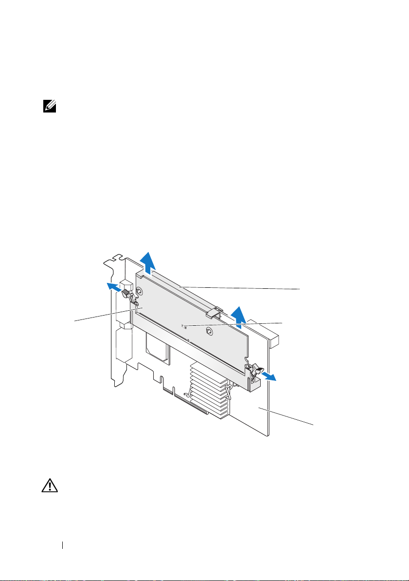
Visually inspect the controller and determine whether the dirty cache LED
on the memory module is turned on. See Figure 1. If the LED is turned on,
reinsert the controller into the system, replace the system cover, reconnect
the system to the electrical outlet, turn on the system, and repeat step 1.
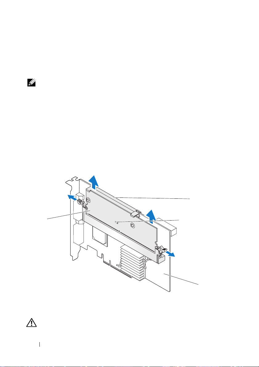
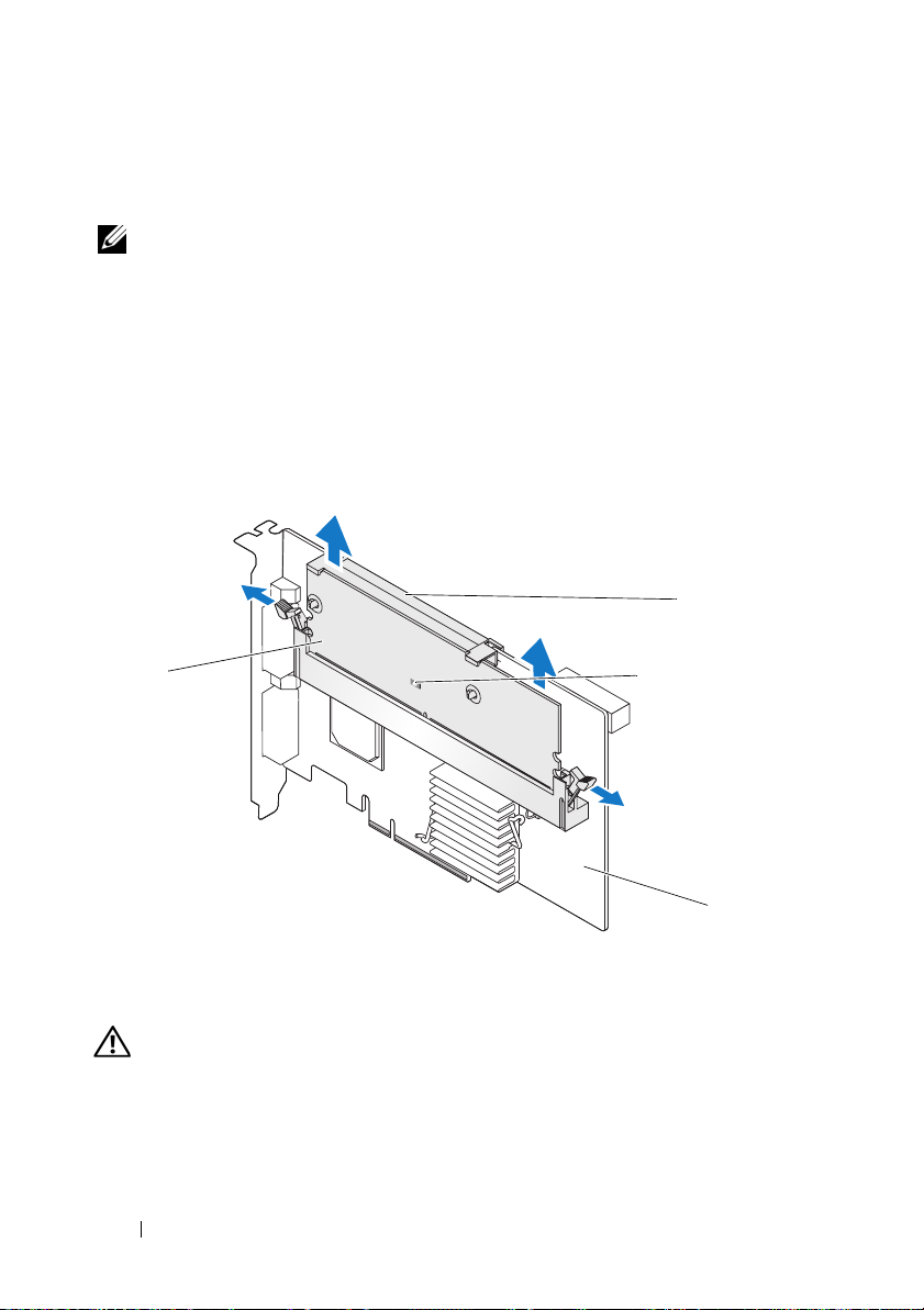
Figure 1. PERC x/E Adapter Dirty Cache LED Location
x
/E Adapter from the system. See the
for more information.
Dell PowerEdge Expandable
2
1
1 memory module 2 battery
3 dirty cache LED 4 PERC x/E Adapter
CAUTION: Running a system without the system cover installed may cause
damage due to improper cooling.
3
4
4 Removing and Installing the Battery and Battery Cable on PERC Controllers
3
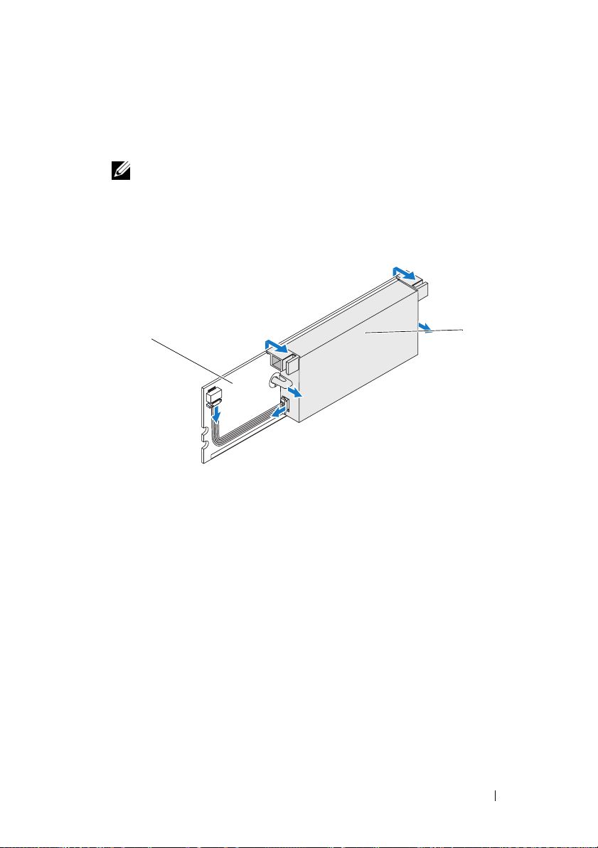
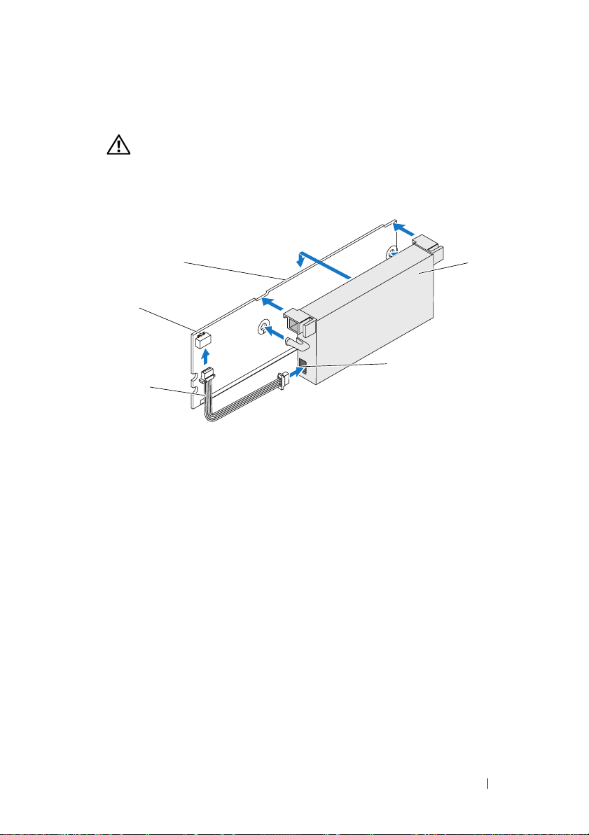
Remove the TBBU assembly from the PERC x/E Adapter by pressing down
on the tabs at each edge of the memory module connector and lifting the
TBBU off the adapter.
4
Disconnect the battery cable from the memory module.
NOTE: Do not exert excessive pressure on the connector on the memory
module while removing the memory module.
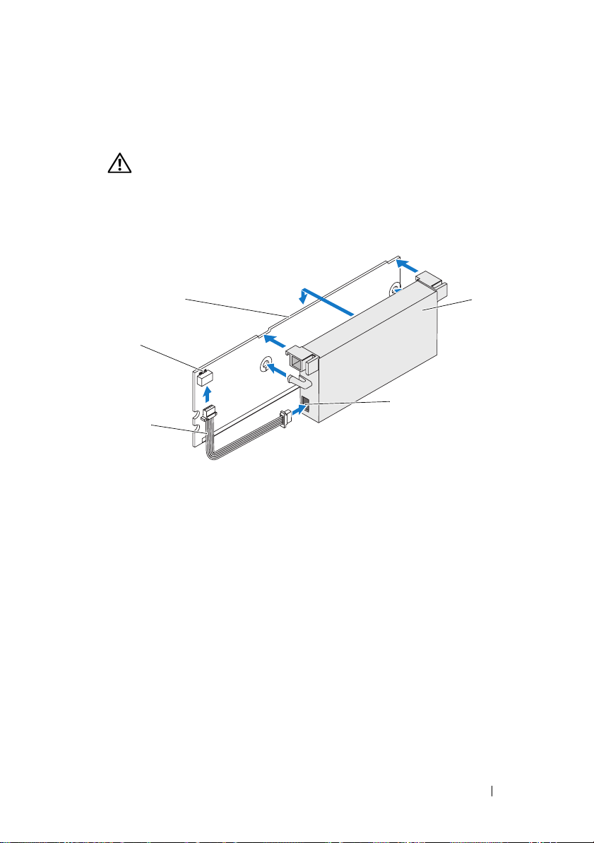
5
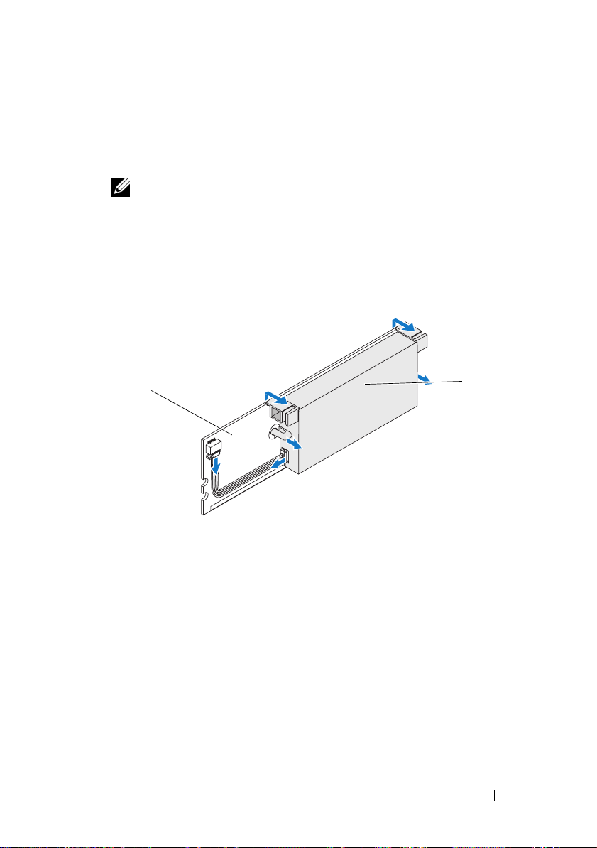
Detach the battery from the memory module by pressing out on the
battery clips inserted through the memory module and rotating the
battery off the memory module. See Figure 2.
Figure 2. Removing the BBU
1
1 memory module 2 battery
2
Removing and Installing the Battery and Battery Cable on PERC Controllers 5
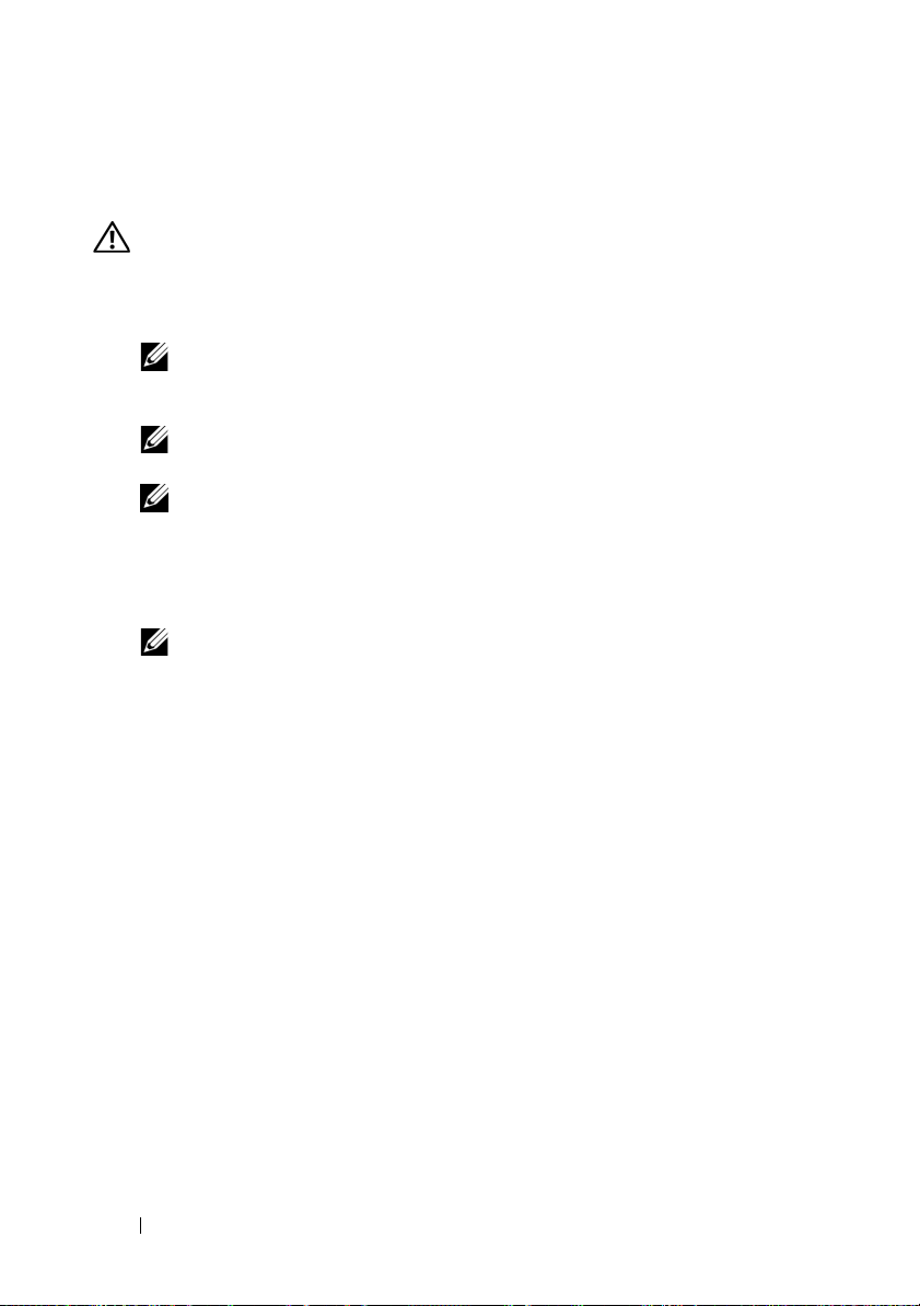
Installing the New BBU and Battery Cable
This section describes the installation of the BBU and battery cable onto the DIMM
of a PERC
1
2
x
/E Adapter.
CAUTION: Only trained service technicians are authorized to remove the system
cover and access any of the components inside the system. Before performing any
procedure, see your Product Information Guide for complete information about
safety precautions, working inside the computer, and protecting against
electrostatic discharge
.
Unpack the BBU and follow all antistatic procedures.
NOTE: All work must be performed at an Electrostatic Discharge (ESD)-safe
workstation to meet the requirements of EIA-625—"Requirements For
Handling Electrostatic Discharge Sensitive Devices." All actions must be
performed following the IPC-A-610 latest revision ESD recommended
practices.
NOTE: Handle all sensitive components in a static-safe area. If possible,
use antistatic floor pads and work bench pads.
NOTE: When unpacking a static sensitive component from its shipping
carton, do not remove the component from the antistatic packing material
until you are ready to install the component. Just before unwrapping the
antistatic package, be sure to discharge static electricity from your body.
With the memory module removed from the controller, insert one end
of the battery cable (the red, white, yellow, and green wires) into the
connector on the memory module and the other end into the connector
on the battery.
NOTE: Do not exert excessive pressure on the connector on the memory
module while installing the memory module.
6 Removing and Installing the Battery and Battery Cable on PERC Controllers
3
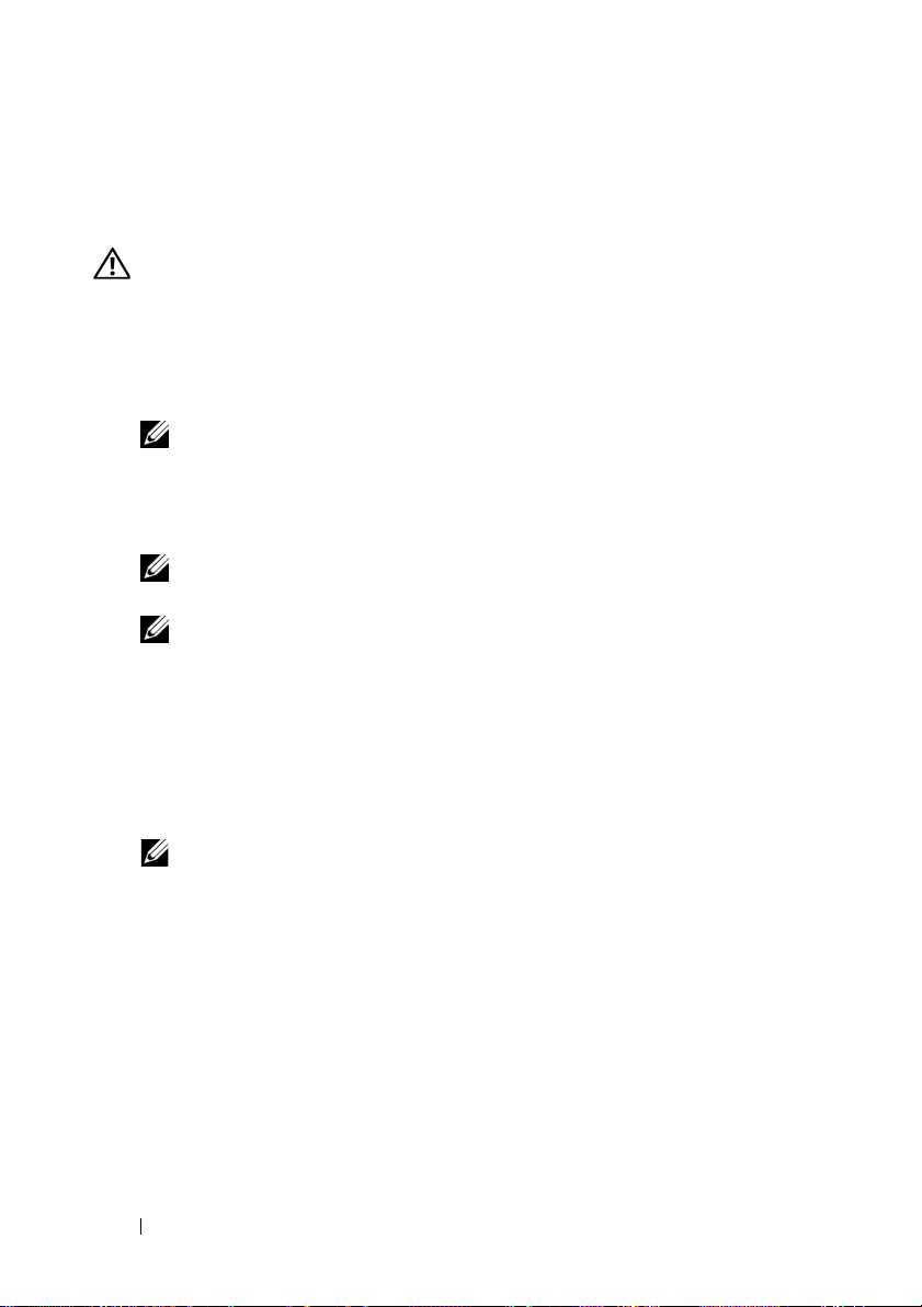
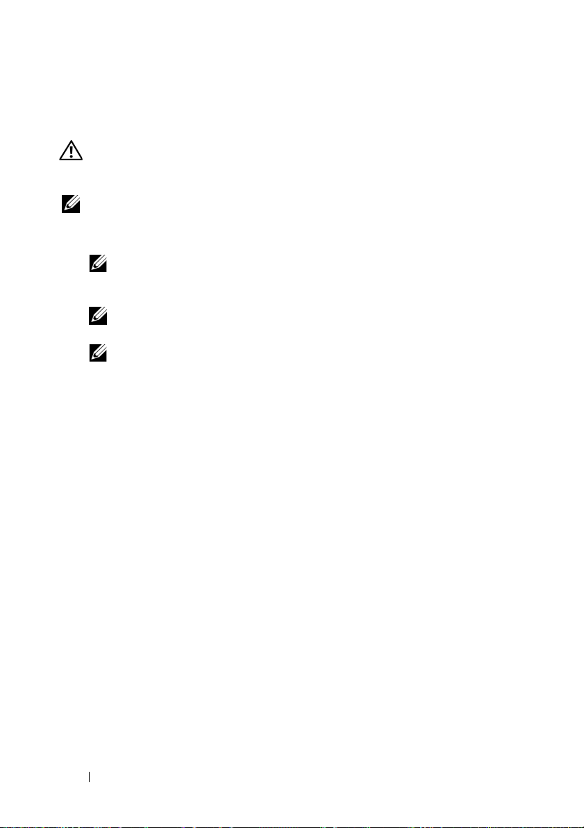
Place the top edge of the battery over the top edge of the memory module
so that the arms on the side of the battery fit into their sockets on the
memory module. See Figure 3.
CAUTION: Electrostatic discharge can damage sensitive components.
Always use proper antistatic protection when handling components.
Touching components without proper grounding can damage the equipment.
Figure 3. Installing the BBU and Battery Cable
1
2
5
3
1 memory module 2 connector on the memory module 3 battery cable
4 battery 5 connector on the battery
4
Place the PERC x/E Adapter on a flat, clean, and static–free surface.
5
Mount the memory module on the controller memory socket like a
4
standard DIMM. See the section "Installing the TBBU on a PERC x/E
Adapter" for more information.
The memory module is mounted flush with the board so that the memory
module is parallel to the board when installed.
6
Press the memory module firmly into the memory socket. As you press the
memory module into the socket, the BBU clicks into place, indicating that
the controller is firmly seated in the socket, and the arms on the socket fit
into the notches to hold the memory module securely.
Removing and Installing the Battery and Battery Cable on PERC Controllers 7
Installing the TBBU on a PERC x/E Adapter
This section describes the procedure to install the memory module on a PERC
x
/E Adapter.
CAUTION: Only trained service technicians are authorized to remove the system
cover and access any of the components inside the system. Before performing any
procedure, see your Product Information Guide for complete information about
safety precautions, working inside the computer, and protecting against
electrostatic discharge.
NOTE: The TBBU on the PERC x/E Adapter consists of a dual in-line memory
module (DIMM) and a battery backup unit (BBU).
1
Remove the memory module in an antistatic environment.
NOTE: When unpacking a static-sensitive component from its shipping
carton, do not remove the component from the antistatic packing material
until you are ready to install the component. Just before unwrapping the
antistatic package, be sure to discharge static electricity from your body.
NOTE: Handle all sensitive components in a static-safe area. If possible,
use antistatic floor pads and work bench pads.
NOTE: Never touch the gold leads and do not bend the memory module.
2
Align the memory module so that the keyed edge of the memory module is
placed exactly on top of the physical divider on the memory socket of the
controller. This will avoid damage to the memory module.
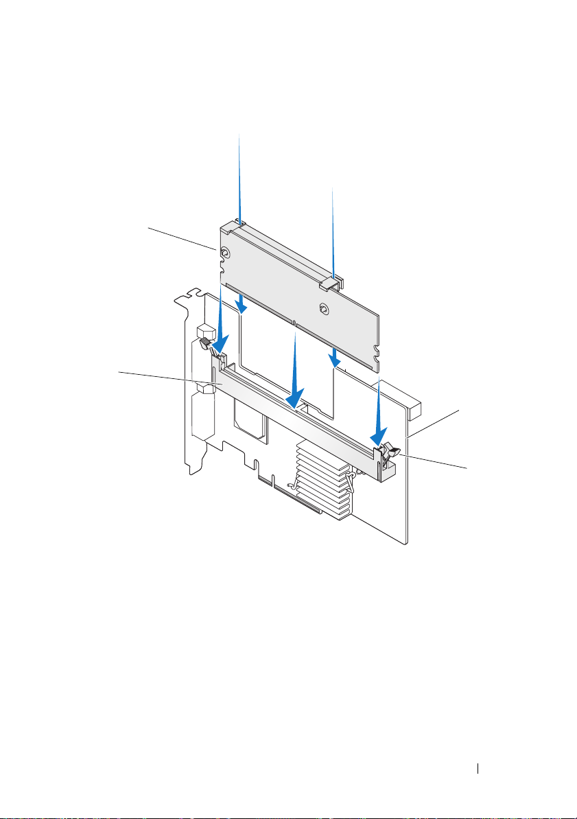
3
Insert the memory module on the memory socket of the controller and
apply a smooth, downward pressure on both ends or on the middle of the
memory module until the retention clips fall into the allotted slots on
either side of the memory module. Figure 4 displays the installation of
a memory module on a PERC
x
/E Adapter.
8 Removing and Installing the Battery and Battery Cable on PERC Controllers

Figure 4. Installing a Dual In-line Memory Module
1
2
3
4
1 memory module 2 memory socket
3PERC x/E Adapter 4 retention clip
Removing and Installing the Battery and Battery Cable on PERC Controllers 9
Removing the DIMM from a PERC x/i Controller
This section describes the procedure to remove the memory module from
aPERC
x
/i Adapter or PERCx/i Integrated controller installed in a system.
CAUTION: Only trained service technicians are authorized to remove the system
cover and access any of the components inside the system. Before performing any
procedure, see your Product Information Guide for complete information about
safety precautions, working inside the computer, and protecting against
electrostatic discharge.
NOTICE: Depending on the generation of your PERC card, the DIMM memory
module may not be removable. PERC 5/i cards include a removable DIMM module.
PERC 6/i cards have an integrated DIMM module which cannot be removed. Do not
attempt the following procedure on a PERC 6/i adapter or integrated controller card.
1
Perform a controlled shutdown of the system in which the PERC x/i
x
controller is installed and remove the PERC
See the
Guide
2
Remove the memory module by pressing down on the tabs at each edge
Dell PowerEdge Expandable RAID Controller x/i and x/E User’s
for more information.
CAUTION: Running a system without the system cover installed may cause
damage due to improper cooling.
/i controller from the system.
of the memory module connector and lifting the memory module off the
controller.
NOTE: Do not exert excessive pressure on the connector on the memory
module while removing the memory module.
NOTE: The location of the PERC x/i Integrated controller varies from system
to system. See the Hardware Owner’s Manual included with the system for
specific information on where the PERC x/i Integrated controller is located.
10 Removing and Installing the Battery and Battery Cable on PERC Controllers
Disconnecting the BBU from a PERC x/i Controller
This section describes the procedure to disconnect the BBU on a PERC x/i
Adapter or PERC
CAUTION: Only trained service technicians are authorized to remove the system
cover and access any of the components inside the system. Before performing any
procedure, see your Product Information Guide for complete information about
safety precautions, working inside the computer, and protecting against
electrostatic discharge.
NOTE: PERC x/i Adapters installed in Dell Precision™ workstations or PowerEdge
SC servers do not have a BBU.
1
Perform a controlled shutdown of the system in which the PERC x/i
controller is installed.
2
Disconnect the system from the electrical outlet and remove the system
cover.
NOTE: See the Hardware Owner’s Manual included with the system for more
3
Locate the PERC x/i controller in the system and visually inspect the
controller to determine whether the dirty cache LED on the controller is
turned on. If the LED is turned on, replace the system cover, reconnect
the system to power, turn the system on and repeat steps 1 and 2.
CAUTION: Running a system without the system cover installed may cause
4
Locate the battery cable connection next to the memory module on the
controller, and disconnect the battery.
See the
on removing the BBU from the system chassis. The location of the TBBU
for the PERC
x
/i Integrated controller while it is installed in a system.
information on removing and reinstalling the system cover.
damage due to improper
Hardware Owner’s Manual
x
/i controller varies from system to system.
cooling.
included with the system for information
Removing and Installing the Battery and Battery Cable on PERC Controllers 11
Installing the DIMM and BBU to a PERC x/i controller
This section describes the installation of the TBBU on a PERC x/i Adapter or
PERC
x
/i Integrated controller.
CAUTION: Only trained service technicians are authorized to remove the system
cover and access any of the components inside the system. Before performing any
procedure, see your Product Information Guide for complete information about
safety precautions, working inside the computer, and protecting against
electrostatic discharge.
NOTICE: Depending on the generation of your PERC card, the DIMM memory
module may not be removable. PERC 5/i cards include a removable DIMM module.
PERC 6/i cards have an integrated DIMM module which cannot be removed. Do not
attempt the following procedure on a PERC 6/i adapter or integrated controller card.
NOTE: Charge the PERC x battery before initial use to attain full functionality.
1
Unpack the DIMM and BBU and follow all antistatic procedures.
NOTE: All work must be performed at an Electrostatic Discharge (ESD)-safe
workstation to meet the requirements of EIA-625—"Requirements For Handling
Electrostatic Discharge Sensitive Devices." All actions must be performed
following the IPC-A-610 latest revision ESD recommended practices.
NOTE: Handle all sensitive components in a static-safe area. If possible,
use antistatic floor pads and work bench pads.
NOTE: When unpacking a static sensitive component from its shipping
carton, do not remove the component from the antistatic packing material
until you are ready to install the component. Just before unwrapping the
antistatic package, be sure to discharge static electricity from your body.
2
Locate the battery cable connection next to the memory module on the
controller, and connect the battery.
NOTE: Do not use excessive pressure on the connector on the memory
module while installing the memory module.
3
Align the memory module so that the keyed edge of the memory module
is placed exactly on top of the physical divider on the memory socket of the
controller. This will avoid damage to the memory module.
4
Insert the memory module on the memory socket of the controller and
apply a smooth, downward pressure on both ends or on the middle of the
memory module until the retention clips fall into the allotted slots on
either side of the memory module.
12 Removing and Installing the Battery and Battery Cable on PERC Controllers

Dell™ PowerEdge™
可扩充
在
PERC
RAID
控制器
x
控制器上拆装电
池和电池电缆

注、注意和警告
注:“注”表示可以帮助您更好地使用计算机的重要信息。
注意:“注意”表示可能会损坏硬件或导致数据丢失,并告诉您如何避免
此类问题。
警告:“警告”表示可能会出现导致财产损失、人身伤害甚至死亡的情况。
____________________
本说明文件中的信息如有更改,恕不另行通知。
© 2007 Dell Inc.
未经
Dell Inc.
本文中使用的商标:
本文件中述及的其它商标和产品名称是指拥有相应商标和名称的公司或其制造的产品。
Dell Inc.
型号
UCP-50 和 UCP-51
2007 年 11
版权所有,翻印必究。
书面许可,严禁以任何形式进行复制。
Dell、DELL
对本公司的商标和产品名称之外的其它商标和产品名称不拥有任何专有权。
月
P/N XR434
徽标、
Dell Precision 和 PowerEdge 是 Dell Inc.
修订版
A00
的商标。

在
PERC
池电缆
控制器上拆装电池和电
本说明文件介绍如何在
上拆装电池、电池电缆和内存模块的信息。
•
有关
PERC x/E
息,请参阅第
•
有关
PERC x/i
Dell™ PowerEdge™
(其中
16
电池拆装过程的信息,请参阅第
表示第几代卡,如 5、6 等)电池拆装过程的信
x
页
可扩充
RAID
22
控制器
页
(PERC)
重要安全信息
警告: 任何需要拆卸系统护盖的安装均只限经过培训的维修技术人员进行。
有关安全预防措施、拆装计算机内部组件以及防止静电释放的完整信息,
请参阅随系统提供的 《产品信息指南》。
注:有关美国销售条款和条件、有限保修与退回规定、出口法规、软件许
可协议以及安全、环境和人机工程学说明、管制通告、循环利用信息等的完
整内容,请参阅随系统提供的《产品信息指南》。
在
控制器上拆装电池和电池电缆 15
PERC
从
PERC x/E
本节介绍从安装在系统中的
注:
电池备用单元
1
对安装了
关闭,并从系统中卸下
适配器上卸下移动式电池备用单元
适配器上卸下
由一块双列直插式内存模块
适配器。有关详细信息,请参阅
PERC x/E
PERC x/E
PERC x/E
适配器上的
(BBU)
TBBU
构成。
适配器的系统以及任何连接的存储设备执行从容
PERC x/E
(TBBU)
TBBU
的过程。
(DIMM)
Dell PowerEdge Expandable RAID Controller x/i and x/E User’s Guide
(
Dell PowerEdge
2
通过外观来检查控制器,并确定内存模块上的已占用高速缓存
否亮起。请参阅图
可扩充
。如果
1
RAID
LED
控制器
x/i 和 x/E
用户指南)。
已亮起,则将控制器重新插入系统中,
装回系统护盖,将系统重新连接至电源插座,打开系统,然后重复
步骤 1。
和一个
LED
是
图
1. PERC x/E
1
警告:如果运行系统时未安装系统护盖,则可能会由于冷却不当而导致设
备损坏。
适配器已占用高速缓存
内存模块
1
已占用高速缓存
3
LED
LED
位置
2
4
电池
PERC x/E
3
适配器
2
4
16 在
控制器上拆装电池和电池电缆
PERC
3
按下内存模块连接器两侧的卡舌并从适配器中提起内存模块
从
PERC x/E
4
从内存模块上断开电池电缆连接。
注:卸下内存模块时,请勿过度用力挤压内存模块上的连接器。
5
向外按压插入内存模块中的电池固定夹并旋转电池使之脱离内存
模块,从内存模块中卸下电池。请参阅图
图
卸下
2.
BBU
适配器中卸下
TBBU
部件。
。
2
TBBU
,
1
1
内存模块
电池
2
2
在
控制器上拆装电池和电池电缆 17
PERC
安装新
本节介绍如何将
警告:只有经过培训的维修技术人员才有权卸下系统护盖并拆装系统内部
的任何组件。在执行任何过程之前,请参阅《产品信息指南》,获取有关安
全预防措施、拆装计算机内部组件以及防止静电释放的完整信息
打开
1
2
从控制器中卸下内存模块后,将电池电缆(红、白、黄和绿线)的一
和电池电缆
BBU
和电池电缆安装到
BBU
PERC x/E
适配器的
DIMM
。
包装,并遵循所有防静电过程。
BBU
注: 所有工作均必须在无静电释放
“处理静电释放敏感设备需求”的要求。执行所有操作时,必须遵循
IPC-A-610
注:请在无静电的工作区内处理所有的敏感组件。如果可能,
请使用防静电的地板垫和工作台垫。
注:打开包装箱取出静电敏感组件时,如果不准备安装此组件,请不
要将其从防静电包装材料中取出。打开防静电包装之前,应确保已导
去身上的静电。
最新版本
建议的方法。
ESD
的工作站上执行,以满足
(ESD)
端插入内存模块上的连接器中,将另一端插入电池上的连接器中。
注: 安装内存模块时,请勿过度用力挤压内存模块上的连接器。
中。
EIA-625 -
18 在
控制器上拆装电池和电池电缆
PERC
3
将电池的顶部边缘放在内存模块的顶部边缘之上,以便电池一侧的支
臂可装入内存模块上的插槽中。请参阅图
警告:静电释放可能会损坏敏感组件。拿放组件时,应始终采用正确
的静电防护措施。在未正确接地的情况下触摸组件可能会损坏设备。
图
安装
3.
BBU
和电池电缆
。
3
1
2
3
内存模块
1
电池
4
4
将
PERC x/E
5
在控制器内存插槽中安装内存模块,如标准
请参阅“在
适配器放置在平坦、整洁、无静电的平面上。
PERC x/E
内存模块上的连接器
2
5
电池上的连接器
适配器上安装
TBBU
5
DIMM
”一节。
电池电缆
3
。有关详情,
4
安装内存模块,应使模块与系统板平齐,以便内存模块在安装后与系
统板平行。
6 将内存模块牢固地按入内存插槽中。随着将内存模块按入插槽中,
将卡入到位,这表示控制器已稳固地插入插槽中,同时插槽上的
BBU
支臂也插入槽口中,以确保牢固地把持内存模块。
在
控制器上拆装电池和电池电缆 19
PERC
在
PERC x/E
本节介绍在
警告:只有经过培训的维修技术人员才有权卸下系统护盖并拆装系统内部
的任何组件。在执行任何过程之前,请参阅《产品信息指南》,获取有关安
全预防措施、拆装计算机内部组件以及防止静电释放的完整信息。
注:
电池备用单元
1
在防静电环境中卸下内存模块。
2
对齐内存模块,以便内存模块的键槽边缘正好放在控制器内存插槽上
适配器上安装
PERC x/E
PERC x/E
注: 打开包装箱取出静电敏感组件时,如果不准备安装此组件,请不
要将其从防静电包装材料中取出。打开防静电包装之前,应确保已导
去身上的静电。
注:请在无静电的工作区内处理所有的敏感组件。如果可能,
请使用防静电的地板垫和工作台垫。
注:请勿触摸镀金导线,也不要弯曲内存模块。
适配器上的
(BBU)
TBBU
适配器上安装内存模块的过程。
由一块双列直插式内存模块
TBBU
构成。
(DIMM)
的物理分隔架顶部。这样可以避免损坏内存模块。
3
在控制器的内存插槽上插入内存模块,并在内存模块两侧或中间施
加平稳向下的力,直至固定夹插入内存模块任一侧上分配的插槽中。
显示了如何在
图
4
PERC x/E
适配器上安装内存模块。
和一个
20 在
控制器上拆装电池和电池电缆
PERC
图
安装双列直插式内存模块
4.
1
2
3
4
1
3
内存模块
PERC x/E
适配器
在
内存插槽
2
固定夹
4
控制器上拆装电池和电池电缆 21
PERC
从
PERC x/i
本节介绍从安装在系统中的
控制器中卸下 内存模块
PERC x/i
适配器或集成的
PERC x/i
控制器上卸
下内存模块的过程。
警告:只有经过培训的维修技术人员才有权卸下系统护盖并拆装系统内部
的任何组件。在执行任何过程之前,请参阅《产品信息指南》,获取有关安
全预防措施、拆装计算机内部组件以及防止静电释放的完整信息。
注意:
PERC 5/i
成
DIMM
1
对安装了
PERC
Controller x/i and x/E User’s Guide
和
x/i
x/E
警告: 如果运行系统时未安装系统护盖,则可能会由于冷却不当而导
致设备损坏。
2
按下内存模块连接器两侧的卡舌并从控制器中提起内存模块,从而卸
内存模块可能不可拆卸,具体视您的
DIMM
卡包括一个可拆卸的
模块。请勿在
PERC x/i
控制器。有关详情,请参阅
x
/i
控制器的系统执行从容关闭,并从系统中卸下
DIMM
PERC 6/i
适配器或集成的控制器卡上尝试以下过程。
(
用户指南)。
模块。
PERC 6/i
Dell PowerEdge Expandable RAID
Dell PowerEdge
卡是第几代而定。
PERC
卡拥有一个不可拆卸的集
可扩充
RAID
下内存模块。
注: 卸下内存模块时,请勿过度用力挤压内存模块上的连接器。
注:
PERC x/i
制器位置的具体信息,请参阅系统附带的《硬件用户手册》。
集成控制器的位置随系统不同而异。有关
PERC x/i
控制器
集成控
22 在
控制器上拆装电池和电池电缆
PERC
从
PERC x/i
本节介绍从安装在系统中的
连接的过程。
BBU
警告: 只有经过培训的维修技术人员才有权卸下系统护盖并拆装系统内部
的任何组件。在执行任何过程之前,请参阅《产品信息指南》,获取有关安
全预防措施、拆装计算机内部组件以及防止静电释放的完整信息。
注:安装在
器不配备
1
对安装了
2
断开系统与电源插座的连接,并卸下系统护盖。
3
找到系统中的
器上的已占用高速缓存
控制器中断开
Dell Precision™
。
BBU
PERC x/i
注:有关卸下和重新安装系统护盖的详情,请参阅随系统附带的
《硬件用户手册》。
控制器的系统执行从容关闭。
PERC x/i
连接
BBU
PERC x/i
工作站或
适配器或
PERC x/i
PowerEdge SC
集成控制器上断开
服务器中的
PERC x/i
控制器,通过外观来检查控制器,以确定控制
是否亮起。如果
LED
已亮起,则装回系
LED
统护盖,将系统重新连接至电源插座,打开系统,然后重复步骤
警告:如果运行系统时未安装系统护盖,则可能会由于冷却不当而导
致设备损坏。
4
找到控制器上内存模块旁边的电池电缆连接,然后断开电池连接。
有关从系统机箱中卸下
手册》。
PERC x/i
控制器的
的信息,请参阅随系统附带的《硬件用户
BBU
TBBU
的位置随系统不同而异。
1 和 2
适配
。
在
控制器上拆装电池和电池电缆 23
PERC
将
DIMM 和 BBU
本节介绍在
警告:只有经过培训的维修技术人员才有权卸下系统护盖并拆装系统内部
1
2
3
PERC x/i
的任何组件。在执行任何过程之前,请参阅《产品信息指南》,获取有关安
全预防措施、拆装计算机内部组件以及防止静电释放的完整信息。
注意:
PERC 5/i
成
DIMM
注:首次使用
打开
DIMM 和 BBU
注: 所有工作均必须在无静电释放
“处理静电释放敏感设备需求”的要求。执行所有操作时,必须遵循
IPC-A-610
注:请在无静电的工作区内处理所有的敏感组件。如果可能,请使用
防静电的地板垫和工作台垫。
注:打开包装箱取出静电敏感组件时,如果不准备安装此组件,请不
要将其从防静电包装材料中取出。打开防静电包装之前,应确保已导
去身上的静电。
找到控制器上内存模块旁边的电池电缆连接,然后连接电池。
注: 安装内存模块时,请勿过度用力挤压内存模块上的连接器。
对齐内存模块,以便内存模块的键槽边缘正好放在控制器内存插槽上
安装到
PERC x/i
适配器或
内存模块可能不可拆卸,具体视您的
DIMM
卡包括一个可拆卸的
模块。请勿在
PERC x
PERC 6/i
电池之前,请先充电,以获得最佳性能。
控制器
PERC x/i
模块。
DIMM
适配器或集成的控制器卡上尝试以下过程。
的包装,并遵循所有防静电过程。
最新版本
建议的方法。
ESD
集成控制器上安装
PERC
PERC 6/i
(ESD)
卡拥有一个不可拆卸的集
的工作站上执行,以满足
TBBU
卡是第几代而定。
的物理分隔架顶部。这样可以避免损坏内存模块。
4
在控制器的内存插槽上插入内存模块,并在内存模块两侧或中间施加
平稳向下的力,直至固定夹插入内存模块任一侧上分配的插槽中。
的信息。
EIA-625 -
24 在
控制器上拆装电池和电池电缆
PERC

Dell™ PowerEdge™ 可擴充
RAID 控制器 x
拆裝 PERC 控制器的
電池和電池電纜

註、注意及警告
註:「註」會提供您更有效使用電腦的重要資訊。
注意:「注意」表示可能會損壞硬體或導致資料遺失,並告訴您如何避免
此類問題的發生。
警告:「警告」指出財產、人身可能遭受損害甚或造成死亡。
____________________
本文件中的資訊如有變更,恕不另行通知。
©2007DellInc.版權所有,翻印必究。
未經 Dell Inc. 的書面許可,不得以任何形式進行複製。
本文所用商標:Dell、DELL 標誌、Dell Precision 和 Powe rEd ge 是 Dell Inc. 的商標。
本文件所述及之其他商標或品牌名稱,均各自分屬其商標或產品名稱之申請者或擁
有者所擁有。Dell Inc. 對本公司之外的商標和產品名稱不擁有任何專有權。
型號 UCP-50 和 UCP-51
2007 年 11 月 P/N XR434 Rev. A00
拆裝 PERC 控制器的電池和電池 電纜
本文件提供如何在
電池、電池電纜和記憶體模組的資訊。
•
請參閱第
(即 5、6 等)
請參閱第
•
Dell™ PowerEdge™
28
頁以瞭解
34
頁以瞭解
PERC x/E
PERC x/i
可擴充
RAID
控制器
(PERC)
電池拆裝程序,其中 x 表示第幾代的卡
電池拆裝程序
重要安全說明資訊
警告: 如果有任何安裝動作需要將系統機殼卸下,只能由專業的服務人員來
執行。請參閱系統隨附的產品資訊指南以獲得有關安全措施、在電腦內部工作
以及避免靜電釋放的完整資訊。
註:請參閱系統隨附的產品資訊指南以獲得有關美國銷售的條款與條件、
有限擔保與退貨、出口規定、軟體授權合約、安全說明、環境與人類工程的
指示、管制通告以及回收資訊。
上拆裝
拆裝 PERC 控制器的電池和電池電纜 27
從 PERC x/E 配接卡上卸下移動式電池備援單元 (TBBU)
本節說明從系統中安裝的
註: PERC x/E 配接卡上的 TBBU 由一塊雙排直插式記憶體模組 (DIMM) 和一
個電池備援單元 (BBU) 構成。
1
正常關閉安裝有
然後從系統中卸下
控制器
x/i 和 x/E
2
目測檢查控制器,看記憶體模組上的已佔用快取
1
。如果
閱圖
殼,將系統重新連接至電源插座,開啟系統,然後重複步驟
圖 1. PERC x/E 配接卡已佔用快取記憶體 LED 位置
PERC x/E
PERC x/E
x/E
配接卡。請參閱《
配接卡上卸下
TBBU
的程序。
配接卡的系統以及任何連接的儲存裝置,
Dell PowerEdge
可擴充
使用者指南》以獲得更多資訊。
LED
是否亮起。請參
LED
已亮起,則將控制器重新插入系統中,裝回系統機
2
RAID
1
。
1
記憶體模組
1
已佔用快取記憶體 LED
3
警告:不安裝系統機殼而執行系統,可能會由於冷卻不當而損壞裝置。
電池
2
PERC x/E 配接卡
4
28 拆裝 PERC 控制器的電池和電池電纜
3
4
 Loading...