

Dell N3024, N2048 User Manual

Using MLAG in Dell Networks
A deployment guide for Dell Networking switches
Victor Teeter
Dell Engineering
January 2014
January 2014
A Dell Deployment and Configuration Guide

Revisions
Date
Description
January, 2014
Initial Release
PAPER IS FOR INFORMATIONAL PURPOSES ONLY, AND MAY CONTAIN TYPOGRAPHICAL ERRORS AND TECHNICAL
INACCURACIES. THE CONTENT IS PROVIDED AS IS, WITHOUT EXPRESS OR IMPLIED WARRANTIES OF ANY KIND.
© 2014 Dell Inc. All rights reserved. Reproduction of this material in any manner whatsoever without the express written permission
of Dell Inc. is strictly forbidden. For more information, contact Dell.
PRODUCT WARRANTIES APPLICABLE TO THE DELL PRODUCTS DESCRIBED IN THIS DOCUMENT MAY BE FOUND AT:
http://www.dell.com/learn/us/en/19/terms-of-sale-commercial-and-public-sector Performance of network reference
architectures discussed in this document may vary with differing deployment conditions, network loads, and the like. Third party
products may be included in reference architectures for the convenience of the reader. Inclusion of such third party products does
not necessarily constitute Dell’s recommendation of those products. Please consult your Dell representative for additional
information.
Trademarks used in this text: Dell™, the Dell logo, PowerConnect™, OpenManage™, EqualLogic™, Compellent™, and Force10™
are trademarks of Dell Inc. Other Dell trademarks may be used in this document. Cisco Nexus®, Cisco MDS®, Cisco NX-0S®, and
other Cisco Catalyst® are registered trademarks of Cisco System Inc. Microsoft®, Windows®, Windows Server®, Internet Explorer®,
MS-DOS®, Windows Vista® and Active Directory® are either trademarks or registered trademarks of Microsoft Corporation in the
United States and/or other countries. Broadcom® and NetXtreme® are registered trademarks of Broadcom Corporation. Qlogic is a
registered trademark of QLogic Corporation. Other trademarks and trade names may be used in this document to refer to either
the entities claiming the marks and/or names or their products and are the property of their respective owners. Dell disclaims
proprietary interest in the marks and names of others.
2 Using MLAG in Dell Networks
.

Table of Contents
Revisions ............................................................................................................................................................................................. 2
Executive Summary .......................................................................................................................................................................... 4
1 Introduction ................................................................................................................................................................................ 5
2 Caveats for Enabling MLAG ..................................................................................................................................................... 6
3 Supported Topologies .............................................................................................................................................................. 8
4 Single-Tier Example .................................................................................................................................................................. 9
5 Two-Tier Example ................................................................................................................................................................... 13
6 Using MLAG with VLT or Cisco vPC ..................................................................................................................................... 19
A Additional Resources............................................................................................................................................................... 21
B Configuration details ............................................................................................................................................................... 22
3 Using MLAG in Dell Networks
.

Executive Summary
Multi-switch Link Aggregation or MLAG is a feature that allows two Dell Networking switches to act as a
single switch, provides multiple paths across the network with benefits like:
Failover in cases of failed cables or switches
Increased bandwidth of up to double the bandwidth of a single switch
Elimination of port blocking as well as reconvergence delays of spanning tree
MLAGs are created by connecting a Dell Networking switch to another Dell Networking switch through
Peer-Link ports to create MLAG peers (the two connected switches). Other switches directly connected to
the MLAG peers are unaware that they are connecting to two switches. Two switches appear as a single
switch on the network.
All links in the MLAG can carry data traffic across many physically diverse topologies. In the case of a link
or switch failure, traffic continues to flow with minimal disruption. MLAG optimnizes availability and
bandwidth between attached devices in Dell’s Datacenter and Campus networking solutions.
The following Dell Networking N-series switches support MLAG and may be used in building the
configurations in this white paper:
N2024 N3024 N4032
N2024P N3024P N4032F
N2048 N3024F N4064
N2048P N3048 N4064F
N3048P
4 Using MLAG in Dell Networks
.
MLAG
Secondary MLAG peer
Peer-Link
MLAG
Secondary MLAG peer
Peer-Link
MLAG
Primary MLAG peer
Primary MLAG peer
Partner Switch
Partner Switch Partner Switch
MLAG peers appear
as a single logical
switch to partner
switches on the
network
Simple L2 MLAG
L3 MLAG with mulitple
partner switches
1 Introduction
MLAGs provide an active-active split aggregation deployment across two switches acting as one. MLAG
creates a more resilient network with higher bandwidth capabilities. This white paper discusses MLAGs,
how and when they are used, caveats to look out for, and instructions on how to implement MLAG into
your network.
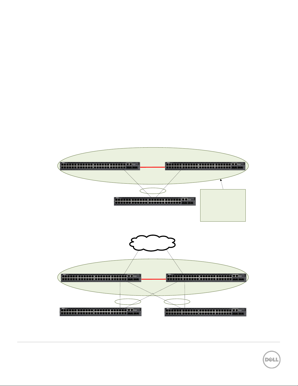
Figure 1 below shows two very basic examples of MLAG domains. In both examples, peer switches are
linked together with a special LAG (one or more cables as denoted by the red line in the pictures below),
called a Peer-Link. With the Peer-Link configured, the two switches appear as a single switch to partner
switches upstream and downstream. Each partner switch contains MLAGs that are simply LAGs (ling
aggregation groups) whose cables are split between the two peers. Primary and secondary peer roles are
chosen automatically by the program when MLAG is enabled.
5 Using MLAG in Dell Networks
Two examples of a single-tier MLAG topology Figure 1
.
MLAG peer
peer
link
MLAG peer
Link Aggregation
MLAG Port-channels
Interfaces
VLANs
Firmware
Spanning Tree
Link Aggregation
MLAG Port-channels
Interfaces
VLANs
Firmware
Spanning Tree
=
=
=
=
=
=
2 Caveats for Enabling MLAG
There are a few limitations in implementing MLAGs:
Two identical switch models are required to create MLAG peers. This means an N2048 can only be
peered with another N2048, an N3024 with another N3024, and so on.
Peer devices must use the same expansion module type if ports from the expansion module are to
be part of the MLAG interface.
Neither of the two switches used as MLAG peers may be stacked with other switches.
MLAG status using the show vpc brief command is only run from the primary MLAG peer
when both the primary and secondary peer information is required.
See the switch User Guide for additional information.
Note: Run the show vpc brief command only from the Primary MLAG peer. This provides
information on both peer switches.
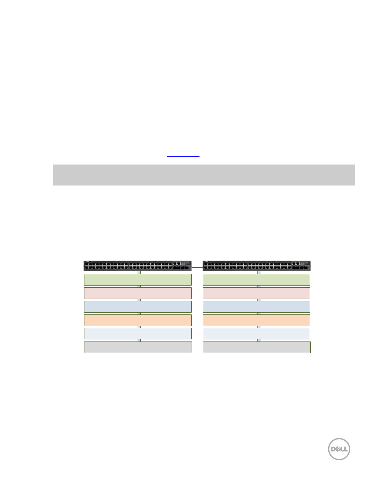
2.1 Consistency of MLAG Peers
As mentioned in the section above, the two switches to be used as MLAG peers must be identical models,
as well as any expansion module that is used in the MLAG peer-link setup. There are also six areas in the
software configuration that must be given special attention to ensure they contain identical information
prior to enabling the MLAG. These areas are reflected in Figure 2.
Figure 2
Consistent MLAG peer configurations
6 Using MLAG in Dell Networks
.
Option category
Settings that need to match on both MLAG peers
Link Aggregation
Hashing mode
Minimum links
Static/dynamic LAG
LACP parameters
o Actor parameters
o Admin key
o Collector max-delay
o Partner parameters
Spanning Tree
Bpdufilter
Bpduflood
Auto-edge
TCN-guard
Cost
Edgeport
Root guard
Loop guard
STP Version
STP MST VLAN configuration
port priority, port cost/mode)
MLAG Port-channels
Port-channel mode
Link speed
Duplex mode
MTU
Bandwidth
VLAN configuration
Interfaces
PFC configuration
CoS queue assignments
VLANs
MLAG VLANs must be configured on both
MLAG peers, and connect to two partner LAGs.
Firmware
Both peers require the same firmware version
to operate correctly.
Misc.
FDB entry aging timers
Static MAC entries
ACL configuration
Change any settings mentioned below on both the MLAG peers when required. Enable MLAG only after
the above settings are configured on the two peer switches.
It is also recommended for MLAG to be temporarily disabled in order to make subsequent changes to the
above settings.
Note: Be sure to schedule down time if making changes that impact traffic or cause data loss.
Note: Failure to make these areas identical may cause sporadic traffic issues on the network which are
difficult to troubleshoot.
7 Using MLAG in Dell Networks
.
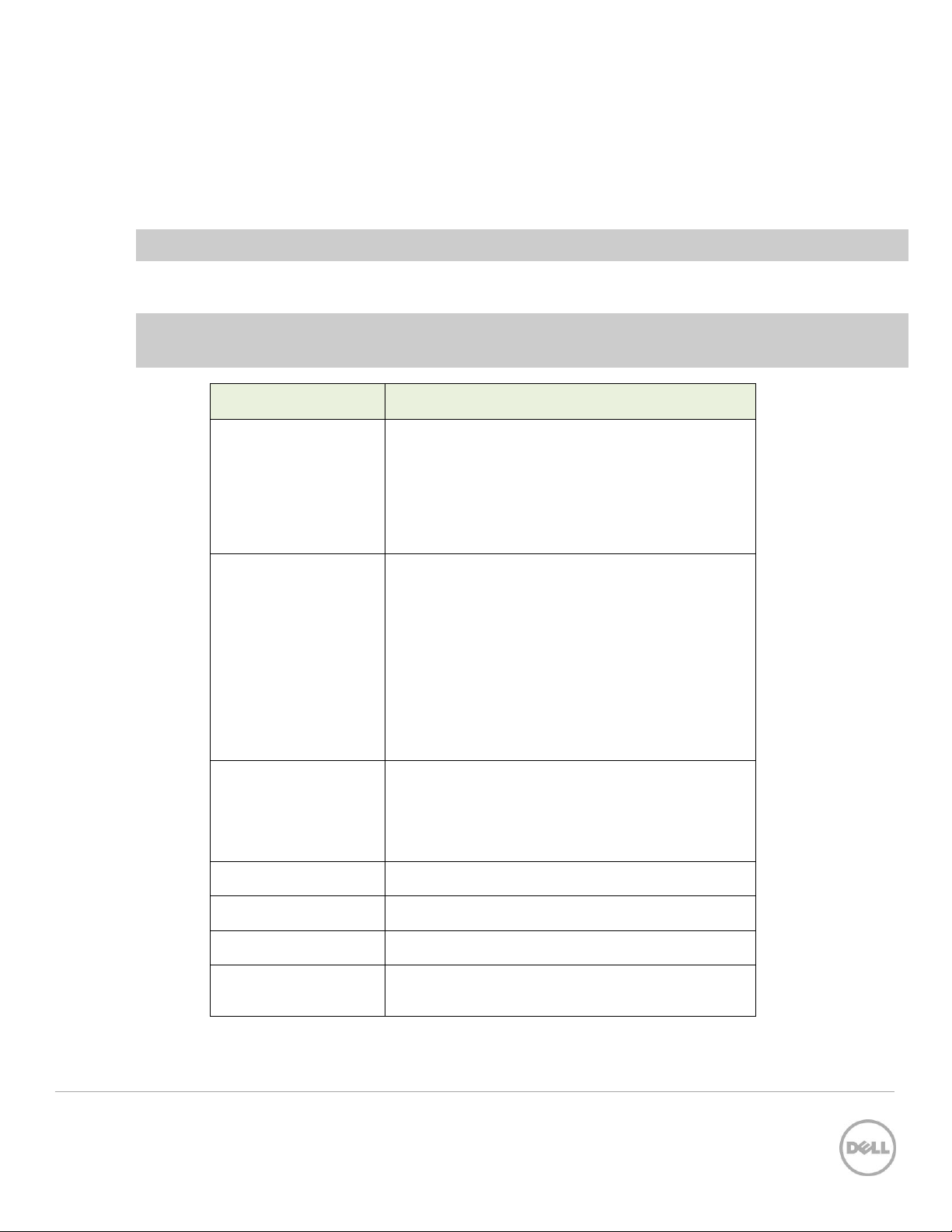
Table 1 Specific configuration options to be equal among MLAG peers
 Loading...