

Page 1

MXG610s Fibre Channel Switch
Module Setup Guide
Supporting fabric OS 8.1.0_Inx
Page 2

Notes, cautions, and warnings
NOTE: A NOTE indicates important information that helps you make better use of
your product.
CAUTION: A CAUTION indicates either potential damage to hardware or loss of
data and tells you how to avoid the problem.
WARNING: A WARNING indicates a potential for property damage, personal injury,
or death.
Copyright © 2018 Dell Inc. or its subsidiaries. All rights reserved. Dell, EMC, and other trademarks
are trademarks of Dell Inc. or its subsidiaries. Other trademarks may be trademarks of their respective
owners.
2018 -07
Rev. A00
Page 3

Contents
1 About this guide.............................................................................. 4
2 MXG610s Setup Guide................................................................... 5
Blade server preparation......................................................................... 5
Switch module installation.......................................................................5
Serial connection...................................................................................... 8
Static IP addresses...................................................................................9
Optical transceivers and cabling installation........................................ 12
Port-side LEDs........................................................................................ 13
Additional country-specic IEEE notices............................................. 14
3 Dell EMC support.......................................................................... 17
Contents 3
Page 4
About this guide
This guide provides site preparation recommendations, step-by-step procedures for rack
mounting and desk mounting, inserting modules, and connecting to a power source.
CAUTION: To avoid electrostatic discharge (ESD) damage, wear grounding wrist
straps when handling this equipment.
WARNING: Only trained and qualied personnel can install this equipment. Read
this guide before you install and power up this equipment. This equipment contains
two power cords. Disconnect both power cords before servicing.
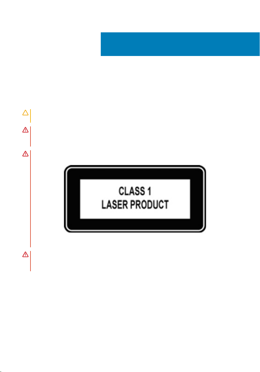
WARNING: This equipment contains optical transceivers, which comply with the
limits of Class 1 laser radiation.
1
Figure 1. Class 1 laser product tag
WARNING: When no cable is connected, visible and invisible laser radiation may be
emitted from the aperture of the optical transceiver ports. Avoid exposure to laser
radiation and do not stare into open apertures.
4 About this guide
Page 5

2
MXG610s Setup Guide
Topics:
• Blade server preparation
• Switch module installation
• Serial connection
• Static IP addresses
• Optical transceivers and cabling installation
• Port-side LEDs
• Additional country-specic IEEE notices
Blade server preparation
Before you insert the switch module in the blade server chassis, meet the following
conditions:
• The blade server is powered up.
• The blade server chassis meets all its specic power requirements.
• The I/O module bay C1 or C2 is empty and ready to receive the switch module.
• If you are replacing an existing switch module, to maintain the proper cooling level in the
chassis, insert the replacement switch module within one minute.
Switch module installation
Insert the switch modules in the blade server chassis slots and check that the modules are
functioning properly.
MXG610s Setup Guide 5
Page 6
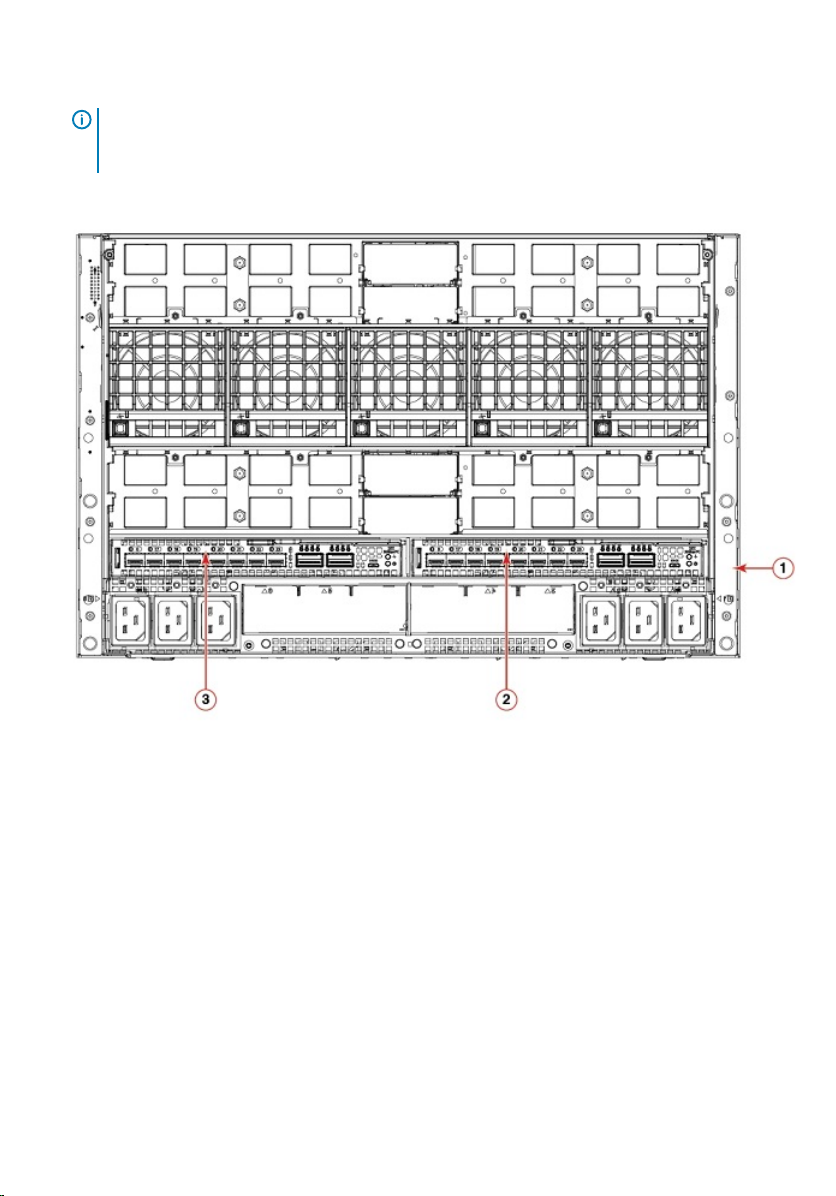
NOTE: The switch module works in switch module slots C1 and C2 in the blade
server chassis. Do not insert the switch module in any other slot because this
action may damage the chassis or switch module connector pins.
1 Remove the orange plastic protective cover for the backplane connector.
Figure 2. Dell EMC PowerEdge MX7000 chassis back view with switch module slots
marked
1
PowerEdge MX7000 chassis back
2 Switch module slot C2
view
3 Switch module slot C1
2 Orient the switch module port side facing you.
The module latch is on the right side.
6
MXG610s Setup Guide
Page 7
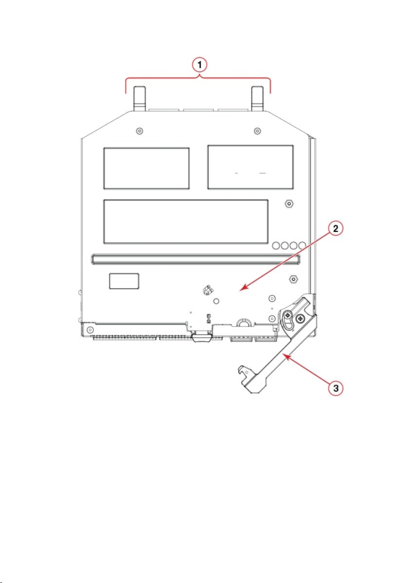
Figure 3. Switch module orientation
1
Backplane connectors 2 Switch module top view
3 Switch module latch in open
position
3 Open the release lever, and slide the switch module into the blade server chassis slot
completely.
MXG610s Setup Guide
7
Page 8

You hear a click when the switch module is locked in the blade server chassis I/O
module bay. If the power is on in the blade server chassis, locking the switch module in
the module bay provides power and turn-ons the switch module and the LEDs.
The switch module then runs POSTs. These tests can take up to two minutes to
complete. After the power/status LED light is steady green for at least two minutes,
the module is ready to use.
4 Start from port 0, then port 17, and then the rest of the ports when cabling the SFP+
ports.
If you use QSFP ports instead of SFP+ ports, transfer the port license from port 0 and
17 to the desired QSFP ports. The QSFP ports must be unused and no additional port
licenses are available. Ports 0 and 17 are prelicensed at the factory.
You are now ready to insert more SFP+/QSFP optical transceivers, if needed. Be sure to
use only Brocade-branded SFP+/QSFP optical transceivers. The FC switch module does
not recognize unapproved products.
Serial connection
To log in to the switch module through the serial connection on the front panel, port-side
view, perform the following steps:
1 Connect the console cable with the micro-USB connector to the console port on the
switch module and to a USB port on the workstation.
2 Disable any serial communication programs running on the workstation such as
synchronization programs.
3 Open a terminal emulator application such as PuTTY, XShell, or SecureCRT on a
Windows PC, or TERM, TIP, or C-Kermit in a LINUX environment. Congure the
application as follows:
• In a WIndows environment, use the following values:
– Bits per second—9600
– Databits—8
– Parity—None
– Stop bits—1
– Flow control—None; must be disabled on the host side
NOTE
: Flow control is not supported on the serial connection when attached
to a remote terminal. You must disable ow control on the customer-side
remote terminal server in addition to the host-side clients.
8 MXG610s Setup Guide
Page 9
• In a UNIX environment using TIP, enter tip /dev/ttyb -9600. at the prompt.
• If you are already using ttyb, use ttya instead and enter tip /dev/ttya -9600
at the prompt.
4 Press enter when the terminal emulator application stops reporting information to
display the login prompt.
Switch Console Login:
Log in to the switch module as admin, using the default password: password.
5
You are prompted to change the default admin and user passwords at initial login. Write
down the new passwords, and keep this information in a secure location.
Fabric OS (swDir)
swDir login: admin
Password:
Please change your passwords now.
Use Control-C to exit or press 'Enter' key to proceed.
swDir:admin>
6 (Optional) Modify passwords.
To skip modifying the password, press Ctrl+C.
NOTE: Passwords are 8 to 40 characters long. They must begin with an
alphabetic character. They can include numeric characters, the period (.), and
the underscore (_) only. Passwords are case-sensitive, and do display when
you enter them on the command line.
Static IP addresses
Dell EMC recommends conguring the switch module through the blade server chassis
management GUI, namely, Dell EMC OpenManage Enterprise Modular. Use this
management GUI to congure the switch IP address and perform advanced conguration
tasks. By default, the IP address mode is set to DHCP. Use this GUI to assign a static IP
address. To congure the FC switch module, follow these steps:
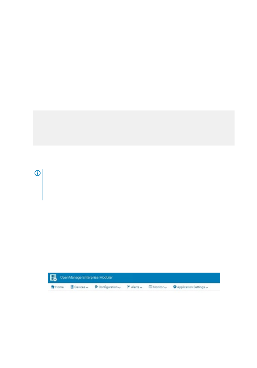
1 Log in to the blade server chassis management GUI application.
Figure 4. OpenManage Enterprise modular
2 Select Devices > I/O modules.
MXG610s Setup Guide
9
Page 10
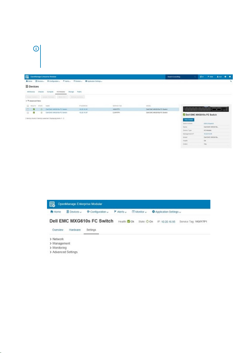
The I/O modules display.
NOTE: You may also access the WebTools conguration UI to manage the
switch module by typing the switch module IP address into any supported web
browser.
Figure 5. I/O modules list
3 Select the I/O module name, IP address, or View Details on the right side of the
display.
The Overview tab is displayed. Select the Settings tab.
Figure 6. Settings tab
4 Click and expand the Network option. Select the required check boxes, and complete
the IPv4 or IPv6 settings, DNS server settings, and optionally the management VLAN
ID. Click
10
Apply.
MXG610s Setup Guide
Page 11
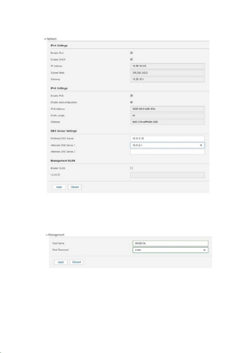
Figure 7. Networking settings
5 Click and expand the Management option. Specify a hostname and root password.
Click Apply.
Figure 8. Management settings
6 Click and expand the Monitoring option. Select the Enable SNMP check box, the
SNMP version, and enter a read community string. Click Apply.
MXG610s Setup Guide
11
Page 12
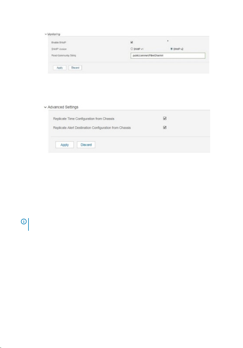
Figure 9. Monitoring settings
7 Click and expand the Advanced Settings option. Select the needed check boxes.
Figure 10. Advanced settings
8 Click Apply.
You have congured the IP address and other settings for the switch module.
Optical transceivers and cabling installation
: When cabling SFP+ optical transceivers, start from port 0, then port 17, and
NOTE
then the other ports.
To insert the optical transceivers and the cable connections:
1 Insert the optical transceiver in an external port on the switch module until it is rmly
seated and the latching mechanism clicks.
Transceivers are keyed to ensure correct orientation. If a transceiver does not install
easily, ensure that it is correctly oriented.
2 Insert the ber optic cable in the SFP+ or QSFP optical transceiver until the latching
mechanism clicks.
Cable connectors are keyed to ensure correct orientation. If a cable connector does not
install easily, ensure that it is correctly oriented.
12
MXG610s Setup Guide
Page 13
For instructions specic to a cable type, see the cable manufacturer’s documentation.
Port-side LEDs
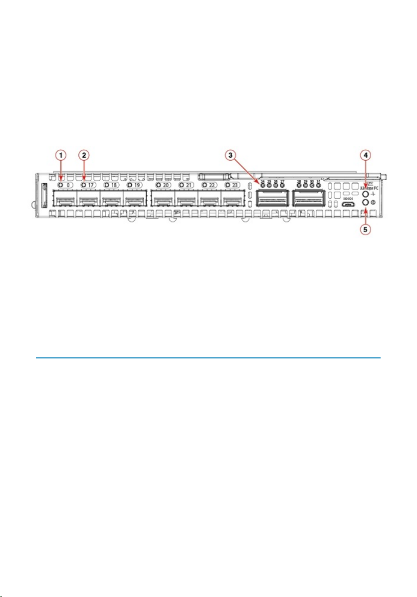
Each switch module uses bicolored external LEDs to indicate operation status. After you
install the switch module in a blade server chassis I/O module, the LEDs become active.
Figure 11. Switch module front panel LEDs
1 FC port 0 status LED 2 FC port 17 status LED
3 FC port 24 status LED 4 Module power status LED
5 Module identication LED
Table 1. Port-side LEDs
LED Description
Module power and status LED
Module identication LED
• Solid green—The switch is working
correctly.
• Blinking amber—The switch is working
incorrectly. The temperature may be too
high, a software error has occurred, or
another error is discovered.
• O—There is no power supplied to the
FC switch module. Reseat the module
and ensure that the chassis power is on
and it has adequate power for the I/O
module.
• O—Module is not identied.
MXG610s Setup Guide 13
Page 14
LED Description
• Blinking blue—Module is being
identied.
FC port status LED
• Both o—No light or signal carrier—no
module, no cable—for the media
interface
• Solid amber—Receiving light or signal
carrier, but not yet online
• Slow ashing amber, 2-second intervals
—Disabled; results of diagnostics or the
portdisable command.
• Fast ashing amber, 1/2-second
intervals—Error occurred, fault with
port.
• Solid green—Online; connected with
external device over cable
• Slow ashing green, 2-second intervals
—Online but segmented; Loopback
cable or incompatible switch.
• Fast ashing green, 1/2-second intervals
—Internal loopback, diagnostic.
• Flickering green—Online and frames
owing through the port.
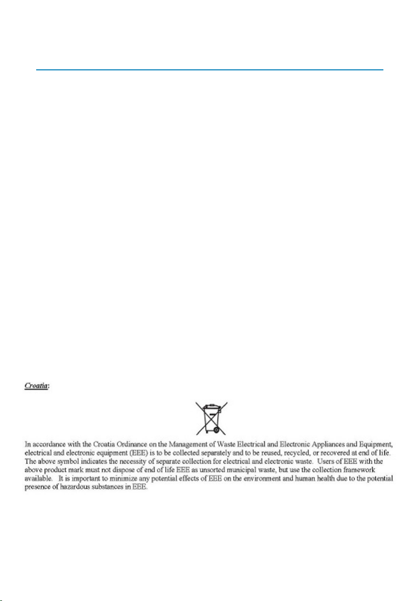
Additional country-specic IEEE notices
Figure 12. Croatia
14
MXG610s Setup Guide
Page 15
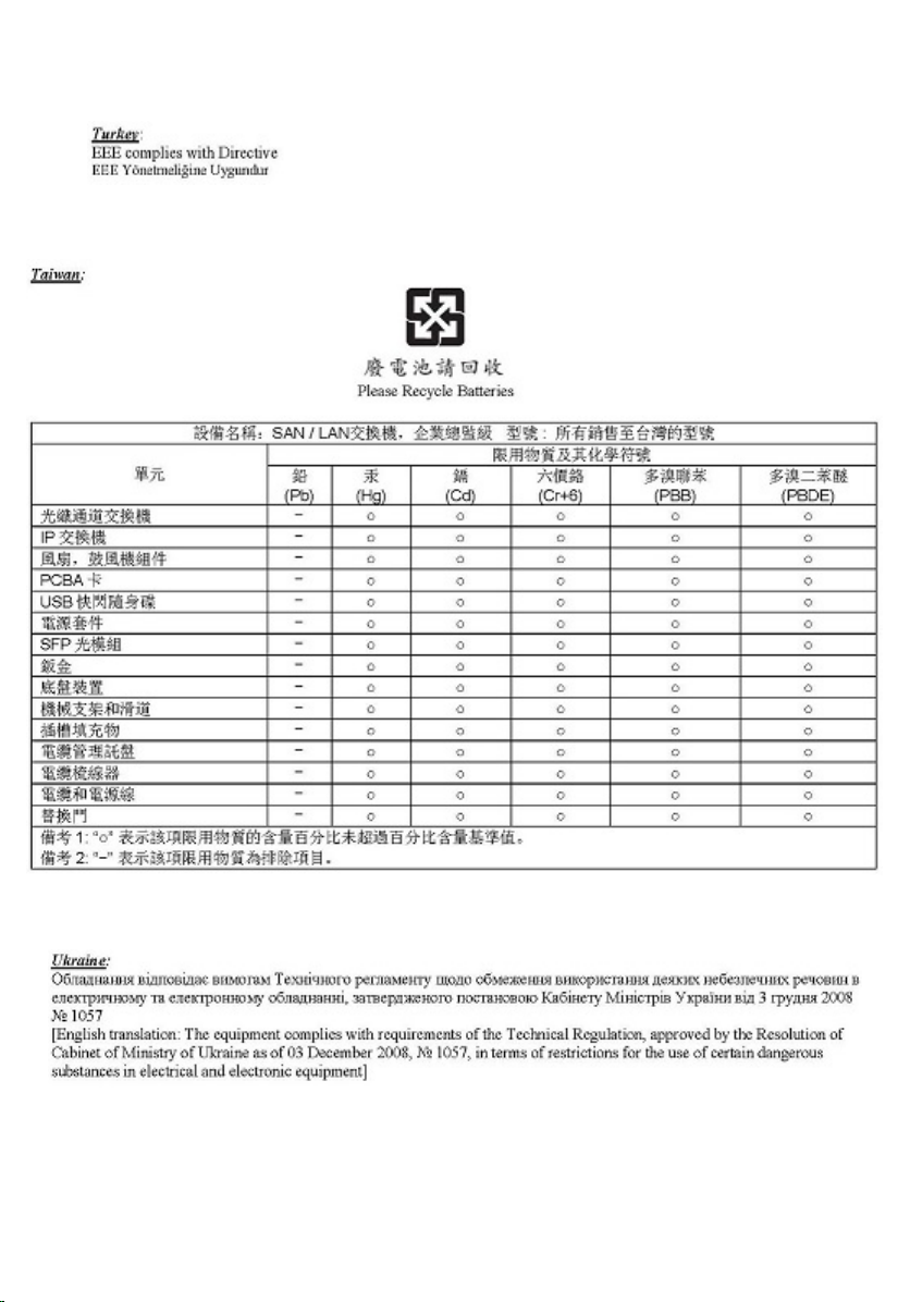
Figure 13. Turkey
Figure 14. Taiwan
Figure 15. Ukraine
MXG610s Setup Guide
15
Page 16
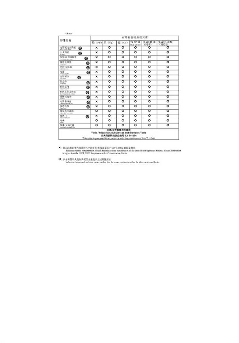
Figure 16. China
16 MXG610s Setup Guide
Page 17

Dell EMC support
The Dell EMC support site provides documents and tools to help you eectively use Dell
EMC equipment and mitigate network outages. Through the support site you can obtain
technical information, access software upgrades and patches, download available
management software, and manage your open cases. The Dell EMC support site provides
integrated, secure access to these services.
To access the Dell EMC support site, go to www.dell.com/support/. To display information
in your language, scroll down to the bottom of the web page and select your country from
the drop-down menu.
• To obtain product-specic information, enter the 7-character service tag, known as a
luggage tag, or 11-digit express service code of your switch and click Submit.
To view the chassis service tag or express service code, pull out the tag or enter the
show chassis command from the CLI.
• To receive more technical support, click Contact Us. On the Contact Information web
page, click Technical Support.
To access switch documentation, go to www.dell.com/manuals/.
To search for drivers and downloads, go to www.dell.com/drivers/.
3
To participate in Dell EMC community blogs and forums, go to www.dell.com/community.
Dell EMC support 17
 Loading...