

Dell Md3400, md3420 User Manual

Dell PowerVault MD3400 and MD3420
Storage Arrays
Owner's Manual
Regulatory Model: E03J and E04J Series
Regulatory Type: E03J001 and E04J001

Notes, Cautions, and Warnings
NOTE: A NOTE indicates important information that helps you make better use of your computer.
CAUTION: A CAUTION indicates either potential damage to hardware or loss of data and tells you
how to avoid the problem.
WARNING: A WARNING indicates a potential for property damage, personal injury, or death.
Copyright © 2014 Dell Inc. All rights reserved. This product is protected by U.S. and international copyright and
intellectual property laws. Dell™ and the Dell logo are trademarks of Dell Inc. in the United States and/or other
jurisdictions. All other marks and names mentioned herein may be trademarks of their respective companies.
2014 - 02
Rev. A00

Contents
1 About Your System....................................................................................................7
Introduction........................................................................................................................................... 7
Front-Panel Features and Indicators.................................................................................................... 7
Back-Panel Features and Indicators...................................................................................................10
Physical-Drive Indicator Patterns....................................................................................................... 10
Power Supply and Cooling Fan Features............................................................................................ 11
Power Indicator Codes and Features..................................................................................................11
Related Documentation...................................................................................................................... 12
2 Controller Modules................................................................................................ 13
RAID Controller Modules.................................................................................................................... 13
RAID Controller Module Connectors and Features........................................................................... 13
RAID Controller Module—Additional Features...................................................................................14
Battery Backup Unit.......................................................................................................................14
Storage Array Thermal Shutdown.................................................................................................15
System Password Reset.................................................................................................................15
Cache Functions and Features............................................................................................................15
Cache Mirroring.............................................................................................................................15
Write-Back Cache..........................................................................................................................15
Write-Through Cache................................................................................................................... 15
3 Installing Array Components............................................................................... 17
Recommended Tools.......................................................................................................................... 17
Front Bezel (Optional)..........................................................................................................................17
Removing the Front Bezel............................................................................................................. 17
Installing the Front Bezel............................................................................................................... 17
Physical Drives.....................................................................................................................................18
SAFETY Models AMT E03J and E04J............................................................................................18
Removing a 2.5 Inch Physical-Drive Blank...................................................................................18
Installing a 2.5 Inch Physical-Drive Blank.....................................................................................18
Removing a 3.5 Inch Physical-Drive Blank...................................................................................18
Installing a 3.5 Inch Physical-Drive Blank.....................................................................................19
Removing a Hot-Swap Physical Drive.......................................................................................... 19
Installing a Hot-Swap Physical Drive............................................................................................20
Removing a Physical Drive From a Physical-Drive Carrier...........................................................21
Installing a Physical Drive Into a Physical-Drive Carrier.............................................................. 22
RAID Controller Module .....................................................................................................................22
Removing a RAID Controller Module Blank................................................................................. 23

Installing a RAID Controller Module Blank................................................................................... 23
Removing a RAID Controller Module .......................................................................................... 23
Installing a RAID Controller Module ............................................................................................24
Opening the RAID Controller Module ......................................................................................... 25
Closing the RAID Controller Module............................................................................................25
RAID Controller Module Backup Battery Unit ...................................................................................26
Removing the RAID Controller Module Backup Battery Unit .....................................................26
Installing the RAID Controller Module Backup Battery Unit........................................................26
Power Supply/Cooling Fan Module....................................................................................................27
Removing a Power Supply/Cooling Fan Module......................................................................... 27
Installing a Power Supply/Cooling Fan Module...........................................................................28
Control Panel...................................................................................................................................... 29
Removing the Control Panel........................................................................................................ 29
Installing the Control Panel.......................................................................................................... 30
Backplane.............................................................................................................................................31
Removing the Backplane...............................................................................................................31
Installing the Backplane................................................................................................................ 33
4 Troubleshooting Your System............................................................................ 35
Safety First—For You and Your System.............................................................................................. 35
Troubleshooting Storage Array Startup Failure..................................................................................35
Troubleshooting Loss of Communication.........................................................................................35
Troubleshooting External Connections............................................................................................. 35
Troubleshooting Power Supply/Cooling Fan Modules..................................................................... 36
Troubleshooting Array Cooling Problems......................................................................................... 36
Troubleshooting Expansion Enclosure Management Modules.........................................................37
If EMM Status LED is Blinking Amber (5 Times per Sequence) ................................................... 37
If the EMM Status LED is Solid or Blinking Amber (2 or 4 Times per Sequence)........................ 37
If the Link Status LEDs are not Green........................................................................................... 37
Troubleshooting RAID Controller Modules........................................................................................37
If the Array Status LED is Solid or Blinking Amber....................................................................... 38
If the Link Status LEDs are not Green...........................................................................................38
Troubleshooting Physical Disks..........................................................................................................38
Troubleshooting Array and Expansion Enclosure Connections....................................................... 39
Troubleshooting a Wet System.......................................................................................................... 39
Troubleshooting a Damaged System.................................................................................................40
Controller Failure Conditions.............................................................................................................40
Critical Conditions........................................................................................................................ 40
Noncritical Conditions.................................................................................................................. 41
Invalid Storage Array......................................................................................................................41
ECC Errors......................................................................................................................................41
PCI Errors....................................................................................................................................... 41

5 Technical Specifications.......................................................................................43
6 Getting Help.............................................................................................................47
Locating Your System Service Tag..................................................................................................... 47
Contacting Dell................................................................................................................................... 47
Documentation Feedback.................................................................................................................. 47

6

1
About Your System
Introduction
The MD3400 and MD3420 Series storage array is designed for high availability, offering redundant access
to data storage. Its features support both single and dual RAID controller configurations.
The Dell PowerVault MD3400 and MD 3420 Series storage array provides 12 Gbps SAS connectivity to the
host server. It enables access for up to eight non-redundant servers or four redundant servers.
The MD3400 and MD3420 Series storage array includes a number of components. These components
are:
• RAID controller module(s)
• PSU/fan modules
• Disk drives (also called physical disks/hard drives in this document)
• A front bezel (optional)
• A system enclosure, into which the other components are plugged
Front-Panel Features and Indicators
Figure 1. Front-Panel Features and Indicators—Dell PowerVault MD3400
7
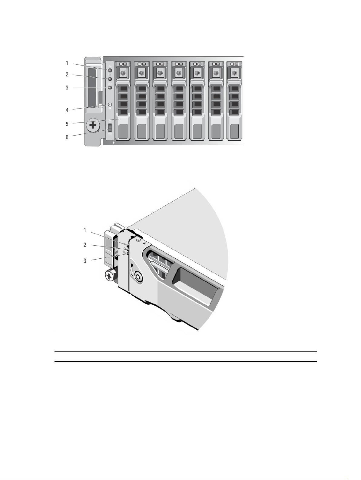
Figure 2. Front-Panel Features and Indicators—Dell PowerVault MD3420
Figure 3. Front-Bezel Features and Indicators
Item Indicator, Button, or Connector Description
1 Enclosure status LED The enclosure status LED lights when the
enclosure power is on.
Lights blue during normal operation.
Blinks blue when a host server is identifying the
enclosure or when the system identification button
is pressed.
8

Item Indicator, Button, or Connector Description
Lights amber as enclosure boots or is reset.
Blinks amber when the enclosure is either in a fault
state or the hosts are not using the preferred path
to a virtual disk.
2 Power LED The power LED lights green when at least one
power supply is supplying power to the enclosure.
3 Split mode LED This LED must be unlit as the split mode function is
not supported by the MD3400 Series Storage
Arrays.
4 System identification button The system identification button on the front
control panel can be used to locate a particular
enclosure within a rack. When the button is
pushed, the system status indicators on the control
panel and the RAID controller module(s) blink blue
until the button is pushed again.
5 Hard drives MD3400—Up to twelve 3.5 inch SAS hot-
swappable hard drives.
MD3420—Up to twenty four 2.5 inch SAS hot-
swappable hard drives.
6 Enclosure mode switch The function of this switch is not applicable to your
storage array. However, if MD1200 Series
expansion enclosures are daisy chained to the
storage array, the enclosure mode switches of the
MD1200 Series expansion enclosures must be set
to the Unified-Mode position.
NOTE: This switch must be set before turning
on the MD1200 Series expansion enclosure.
Changing the switch setting after the
expansion enclosure is turned on has no effect
on the enclosure configuration until the
expansion enclosure goes through a complete
power cycle.
9

Back-Panel Features and Indicators
Figure 4. Back-Panel Features and Indicators—Dell PowerVault MD3400 and MD3420 Series
1. 600 W power supply/cooling fan 2. RAID Controller Module 0
3. RAID Controller Module 1 4. 600 W power supply/cooling fan
Physical-Drive Indicator Patterns
Figure 5. Physical-Drive Indicators
1. physical-drive activity indicator (green) 2. physical-drive status indicator (green and
NOTE: If the physical drive is in Advanced Host Controller Interface (AHCI) mode, the status
indicator (on the right side) does not function and remains off.
Drive-Status Indicator Pattern
(RAID Only)
Blinks green two times per
second
Off Drive ready for insertion or removal
10
Condition
Identifying drive or preparing for removal
NOTE: The drive status indicator remains off until all physical
drives are initialized after the system is turned on. Drives are not
ready for insertion or removal during this time.
amber)

Drive-Status Indicator Pattern
(RAID Only)
Condition
Blinks green, amber, and turns
off
Blinks amber four times per
second
Blinks green slowly Drive rebuilding
Steady green Drive online
Blinks green three seconds,
amber three seconds, and
turns off six seconds
Predicted drive failure
Drive failed
Rebuild aborted
Power Supply and Cooling Fan Features
The MD3400 and MD3420 Series storage array includes two integrated, hot-swappable power supply/
cooling fan modules. Both modules must be installed to ensure proper cooling. The system requires at
least one of the cooling fans to function, to avoid overheating.
A power supply/cooling fan module can be replaced without powering down the system. For information
on removing and installing the modules, see Power Supply/Cooling Fan Module.
Power Indicator Codes and Features
Figure 6. Power Indicator Codes and Features
Item LED Type Icon Description
1 DC power The LED lights green when the DC output voltage is within
the limit.
11

Item LED Type Icon Description
If this LED is off, it indicates that the DC output voltage are
not within the limit.
2 Power supply/
cooling fan fault
3 AC power The LED lights green when the AC input voltage is within
4 Power
connector
5 Power switches
(2)
The LED lights amber when the DC output voltage is not
within the limit or a fault with the fan is detected.
If this LED is off, it indicates that no fault condition is
present.
the limit.
If this LED is off, it indicates either there is no power or the
AC input voltage is not within the limit.
Connect the external power supply to this connector.
The power switch controls the power supply output to the
enclosure.
Related Documentation
NOTE: For all PowerVault documentation, go to dell.com/powervaultmanuals.
NOTE: For all Dell OpenManage documents, go to dell.com/openmanagemanuals.
NOTE: For all storage controller documents, go to dell.com/storagecontrollermanuals.
You product documentation includes:
• Dell PowerVault MD3400/3420/3800i/3820i/3800f/3820f Storage Arrays Getting Started Guide —
Provides an overview of system features, setting up your system, and technical specifications. This
document is shipped with your system.
• Rack Installation Instructions — Describes how to install your system into a rack. This document is
shipped with your rack solution.
• Dell PowerVault MD Series Storage Arrays Administrator's Guide — Provides information about
configuring and managing the system using the MDSM GUI.
• Dell PowerVault Modular Disk Storage Arrays CLI Guide — Provides information about configuring and
managing the system using the MDSM CLI.
• Dell PowerVault MD3400 and MD3420 Storage Arrays Deployment Guide — Provides information
about deploying the storage system in the SAN architecture.
• Dell PowerVault MD34xx and 38xx Series Support Matrix — Provides information about the software
and hardware compatibility matrices for the storage array.
12

2
Controller Modules
RAID Controller Modules
The RAID controller modules provide high-performance, advanced virtual disk configuration, and faulttolerant disk subsystem management. Each RAID controller module contains 4GB or 8GB of mirrored
cache for high availability and a battery-powered cache offload mechanism.
NOTE: The 8GB mirrored cache is an optional feature.
RAID controller modules provide the following data path and enclosure management functions:
• Monitoring and controlling enclosure environment elements (temperature, fans, power supplies, and
enclosure LEDs)
• Controlling access to the physical disks
• Communicating enclosure attributes and states to the host server and management station
Each RAID controller module has multiple SAS IN ports for host access. The ports provide redundant host
connections and support a high availability storage environment. Various configurations can be utilized,
in both single controller (simplex) and dual controller (duplex) modes, to connect the storage enclosure
to hosts depending on specific redundancy needs.
For information on cabling, see the MD3400 and MD3420 Series Storage Arrays Deployment Guide, at
dell.com/powervaultmanuals.
RAID Controller Module Connectors and Features
Figure 7. MD3400 and MD3420 Series SAS RAID Controller Module
13

Item Component Function
1 12Gbps SAS IN port (2) Provides host-to-controller SAS connection.
2 Seven segment display
sequence
3 Controller power LED Lights green when controller power is on.
4 Controller fault LED Lights amber when controller fault is detected.
5 System identification LED Blinks blue when system identification switch push-
6 Cache active or cache offload
LED
7 Battery fault Lights amber when battery backup unit or battery has
8 Management port Provides a 100/1000 Mbps Ethernet connection for
9 Ethernet port (reserved) Reserved port.
10 12Gbps SAS IN port (2) Provides host-to-controller SAS connection.
11 USB port Reserved port.
12 Mini USB port Provides serial connection for debugging.
13 Password reset switch Activating this switch resets the password.
14 SAS OUT Port (2) Provides SAS connection for cabling to a downchain
Displays status or error codes for the storage array.
Turns off when controller is not powered.
Turns off when controller is operating normally
button on enclosure front panel is pressed.
Lights green when on-board controller memory
contains data.
If AC power fails, this LED changes to indicate Cache
offload status. If the password reset function has
successfully changed the password, this LED flashes
on and off briefly.
failed.
Turns off when battery backup unit is operating
normally
out-of-band management of the enclosure.
expansion enclosure.
Using Port 0 is recommended.
RAID Controller Module—Additional Features
Battery Backup Unit
Each RAID controller contains a two-cell Lithium ion nanopolymer battery backup unit (BBU). It provides
power to the RAID controller module in the event of a power outage. For information on removing and
installing the BBU, see RAID Controller Module Backup Battery Unit .
NOTE: For virtual disks, the RAID controller firmware changes the data cache setting based on the
state of the battery. If the battery is missing or does not have sufficient charge, the controller flushes
the cache and sets the write cache attribute to Write Through for all virtual disks. When the battery
is replaced, Write Back is re-enabled.
14

Storage Array Thermal Shutdown
The system automatically shuts down when system temperature exceeds the safe threshold. The battery
backup unit protects against data loss by providing power to offload cache to non-volatile memory in the
event of power loss. It is not necessary to shut down any MD1200 Series expansion enclosures attached
to the storage array when thermal shutdown occurs.
Temperature threshold values determine the temperature at which shutdown occurs. These thresholds
cannot be changed.
Table 1. Shutdown Threshold Type
Threshold Temperature Exceeding Event Description
Nominal failure threshold A critical event is set.
Maximum failure threshold Shutdown of the system power supplies occurs
within 3 minutes.
Shutdown threshold Shutdown of the system power supplies occurs
within 5 seconds.
System Password Reset
The storage array password can be reset if it is forgotten. To reset the password, push and hold down the
password reset switch for at least 5 seconds. The password is deleted.
The RAID controller module allows you to change the password.
NOTE: The reset switch can be accessed by using a small object such as the tip of a pen.
Cache Functions and Features
Cache Mirroring
Cache mirroring function copies accepted host-write data from the primary controller to the partner
controller. This action ensures that host-write data is safely mirrored to the partner controller before
successful completion status is returned to the host. If a controller fails, the surviving controller safely
retains all mirrored data. Cache mirroring is enabled by default.
Write-Back Cache
In write-back cache, write operations result in a completion signal being sent to the host operating
system as soon as the cache receives the data to be written. The target physical disk receives the data at a
more appropriate time to increase controller performance. In dual-active controller configurations with
write-back caching enabled, the write data is always mirrored to the cache of the second controller
before completion status is issued to the host initiator. Write-back cache is enabled by default unless
cache mirroring is disabled.
Write-Through Cache
In write-through cache, data is written to the physical disk before completion status is returned to the
host operating system. Write-through cache is considered more robust than write-back cache, since a
15
 Loading...