

Page 1

Dell PowerVault MD3600f and
MD3620f Storage Arrays With
Microsoft Windows Server
Failover Clusters
Hardware Installation
and Troubleshooting
Guide
Page 2

Notes and Cautions
NOTE: A NOTE indicates important information that helps you make better use of
your computer.
CAUTION: A CAUTION indicates potential damage to hardware or loss of data if
instructions are not followed.
__________________
Information in this publication is subject to change without notice.
© 2011 Dell Inc. All rights reserved.
Reproduction of these materials in any manner whatsoever without the written permission of Dell Inc.
is strictly forbidden.
Trademarks used in this text: Dell™, the DELL logo, PowerEdge™, and PowerVault™ are trademarks
of Dell Inc. Microsoft
Corporation in the United States and/or other countries.
Other trademarks and trade names may be used in this publication to refer to either the entities claiming
the marks and names or their products. Dell Inc. disclaims any proprietary interest in trademarks and
trade names other than its own.
2011 - 07 Rev. A00
®
, Windows®, and Windows Server® are registered trademarks of Microsoft
Page 3

Contents
1 Introduction . . . . . . . . . . . . . . . . . . . . . . . . 7
Overview . . . . . . . . . . . . . . . . . . . . . . . . . . 7
Cluster Solution
. . . . . . . . . . . . . . . . . . . . . . 8
Cluster Requirements . . . . . . . . . . . . . . . . . . . 8
Cluster Nodes
. . . . . . . . . . . . . . . . . . . . . 9
Cluster Storage . . . . . . . . . . . . . . . . . . . 10
Cluster Storage Management Software
Supported Cluster Configurations
Direct-Attached Cluster
SAN-Attached Cluster
. . . . . . . . . . . . . . 12
. . . . . . . . . . . . . . . 13
. . . . . . . . . . . . 12
. . . . . . 10
Configuration Order for Direct-Attached
and SAN-Attached Connections
Direct-Attached Configuration Order
. . . . . . . . . . . . . 14
. . . . . . . 15
SAN-Attached Configuration Order . . . . . . . . 15
Other Documents You May Need
. . . . . . . . . . . . 16
2 Cabling Your Cluster Hardware . . . . . . . . 19
Cabling the Mouse, Keyboard, and Monitor . . . . . . 19
Cabling the Power Supplies
. . . . . . . . . . . . . . . 19
Cabling Your Public and Private Networks
Cabling Your Public Network
. . . . . . . . . . . . 22
. . . . . . . 21
Contents 3
Page 4

Cabling Your Private Network . . . . . . . . . . . 22
Using Dual-Port Network Adapters for
Your Private Network . . . . . . . . . . . . . . . . 23
NIC Teaming
. . . . . . . . . . . . . . . . . . . . . 24
Cabling the Storage Systems
. . . . . . . . . . . . . . 24
Cabling Storage for Your
Direct-Attached Cluster
. . . . . . . . . . . . . . . 24
Cabling Storage for Your
SAN-Attached Cluster . . . . . . . . . . . . . . . 30
Connecting a PowerEdge Cluster to
Multiple PowerVault MD3600f or MD3620f
Storage Systems . . . . . . . . . . . . . . . . . . 38
3 Preparing Your Systems
for Clustering . . . . . . . . . . . . . . . . . . . . . 41
Cluster Configuration Overview . . . . . . . . . . . . . 41
Installation Overview
Installing Supported Fibre Channel HBAs
Installing Fibre Channel HBA
on Your Host Server
Customizing HBA Drivers and
Firmware Settings
Implementing Zoning on a Fibre
Channel Switched Fabric
World Wide Name Zoning
Switch Zoning Requirements
Setting Up Zoning on the Fibre Channel
Switch Hardware
. . . . . . . . . . . . . . . . . . 43
. . . . . . . . 44
. . . . . . . . . . . . . . . . . 44
. . . . . . . . . . . . . . . . . . 44
. . . . . . . . . . . . . . . . 45
. . . . . . . . . . . . . 46
. . . . . . . . . . . . 46
. . . . . . . . . . . . . . . . . . 47
4 Contents
Installing the Storage Management Software
Configuring the Shared Storage System
. . . . . . . . . 48
. . . . . 47
Page 5

Troubleshooting Tools . . . . . . . . . . . . . . . 56
Configuring the RAID Level for the Shared
Storage Subsystem
Windows Operating System and
Dynamic Volumes
Assigning Drive Letters and Mount Points
Naming and Formatting Drives on the
Shared Storage System. . . . . . . . . . . . . . . 61
Using Advanced (Premium) PowerVault
Modular Disk Storage Manager Features
. . . . . . . . . . . . . . . . . . . . 60
. . . . . . . . . . . . . . . . . . 60
. . . . 60
. . . . . 63
Configuring a Failover Cluster
. . . . . . . . . . . . . . 66
A Troubleshooting . . . . . . . . . . . . . . . . . . . . 67
B Cluster Data Form . . . . . . . . . . . . . . . . . . 73
C Zoning Configuration Form . . . . . . . . . . . 77
Index . . . . . . . . . . . . . . . . . . . . . . . . . . . . . . . 79
Contents 5
Page 6

6 Contents
Page 7

1
Introduction
This document provides information for installing and managing your cluster
solution using Dell PowerVault MD3600f and MD3620f storage systems. It is
intended for experienced IT professionals who configure a cluster solution
and for trained service technicians who perform upgrade and maintenance
procedures. This document also addresses readers who are new to clustering.
Overview
The Dell PowerEdge Cluster with Microsoft Windows Server Failover
Clustering combines specific hardware and software components to provide
enhanced availability for applications and services that run on the cluster. A
failover cluster is designed to reduce the possibility of any single point of
failure within the system that can cause the clustered applications or services
to become unavailable. It is recommended that you use redundant
components like system and storage power supplies, connections between the
nodes and the storage array(s), connections to client systems, or other
systems in the multi-tier enterprise application architecture in your cluster.
This guide addresses the configuration of your Dell MD3600f and MD3620f
Fibre
Channel storage arrays for use with one or more Windows Server
failover clusters. It provides information and specific configuration tasks that
enable you to deploy the shared storage for your cluster.
For more information on deploying your cluster, see the Dell Failover Clusters
with Microsoft Windows Server Installation and Troubleshooting Guide at
support.dell.com/manuals.
NOTE: Throughout this document:
• Windows Server 2008 refers to Microsoft Windows Server 2008 x64 Enterprise
Edition or Microsoft Windows Server 2008 R2 x64 Enterprise Edition.
• Dell PowerVault MD36x0f storage array refers to both Dell PowerVault
MD3600f and Dell PowerVault MD3620f storage arrays.
For a list of recommended operating systems, hardware components, and
driver or firmware versions for your Dell Windows Server Failover Cluster, see
the Dell Cluster Configuration Support Matrices at dell.com/ha.
Introduction 7
Page 8

Cluster Solution
Your Fibre Channel cluster implements a minimum of two-node clustering
and a maximum of sixteen-node clustering and provides the following
features:
• 8 Gbps and 4 Gbps Fibre Channel technology.
• High availability of system services and resources to network clients.
• Redundant paths to the shared storage.
• Failure recovery for applications and services.
• Flexible maintenance capabilities, allowing you to repair, maintain, or
upgrade a cluster node without taking the entire cluster offline.
Implementing
advantages:
•
Flexibility
switches without degrading the signal.
•
Availability
providing multiple data paths and greater availability for clients.
•
Connectivity
Computer System Interface (SCSI) or Serial Attached SCSI (SAS).
Because Fibre Channel devices are hot swappable, you can add or remove
devices from the nodes without bringing down the cluster.
Fibre
Channel technology in a cluster provides the following
—Fibre Channel allows a distance of up to 10 km between
—Fibre Channel components use redundant connections,
—Fibre Channel allows more device connections than Small
Cluster Requirements
Your cluster requires the following components:
• Servers (cluster nodes)
• Storage and storage management software
8 Introduction
Page 9

Cluster Nodes
Table 1-1 lists hardware requirements for the cluster nodes.
Table 1-1. Cluster Node Requirements
Component Minimum Requirement
Processor At least one processor for each cluster node.
Cluster Nodes A minimum of two identical PowerEdge systems.
RAM At least 1 GB RAM on each cluster node.
Host Bus Adapter
(HBA) ports
Network
Interface Cards
(NICs)
(public and
private)
Internal Disk
Controller
Two Fibre Channel HBAs per node, unless the server employs an
integrated or supported dual-port Fibre Channel HBA.
At least two NICs—one NIC for the public network and another
NIC for the private network.
NOTE: It is recommended that the NICs on each public network are
identical and that the NICs on each private network are identical.
One controller connected to internal disks for each node. Use any
supported Redundant Array of Independent Disks (RAID)
controller or disk controller.
Two physical disks are required for mirroring (RAID 1) and at least
three are required for disk striping with parity (RAID 5).
NOTE: It is recommended that you use hardware-based RAID or
software-based disk-fault tolerance for the internal drives.
NOTE: For more information about supported systems, HBAs, and operating system
versions, see the Dell Cluster Configuration Support Matrices at dell.com/ha.
Introduction 9
Page 10

Cluster Storage
Table 1-2 provides the configuration requirements for the shared storage
system.
Table 1-2. Cluster Storage Requirements
Hardware
Components
Supported storage
systems
Minimum Requirement
• One Dell PowerVault MD3600f or MD3620f RAID enclosure.
• Any combination of up to seven Dell PowerVault MD1200
and/or MD1220 expansion enclosures.
NOTE: The number of hard drives must not exceed 96.
Cluster nodes All nodes must be directly attached to a single storage system
or attached to one or more storage systems through a SAN.
Switch and cable At least two 8 Gbps Fibre Channel switches in a SAN-attached
environment.
Power and cooling
requirements
Physical disks At least two physical disks in the PowerVault MD3600f or
Multiple clusters and
stand-alone systems
NOTE: RAID 0 and independent disks can be used but are not recommended for a
high-availability system because they do not offer data redundancy if a disk
failure occurs.
Two integrated hot-swappable power supply/cooling fan
modules.
MD3620f RAID enclosure.
In a switch-attached configuration, clusters and stand-alone
systems can share one or more PowerVault MD3600f or
MD3620f systems.
Cluster Storage Management Software
Dell PowerVault Modular Disk Storage Manager
The software runs on the management station or any host attached to the
array to centrally manage the PowerVault MD3600f and MD3620f RAID
enclosures. You can use Dell PowerVault Modular Disk Storage Manager
(MDSM) to perform tasks such as creating disk groups, creating and mapping
virtual disks, monitoring the enclosure status, and downloading firmware.
10 Introduction
Page 11

MDSM is a graphical user interface (GUI) with wizard-guided tools and a
task-based structure. MDSM is designed to:
• Reduce the complexity when you install, configure, manage, and perform
diagnostic tasks for the storage arrays.
• Contain an event monitoring service that is used to send alerts when a
critical problem with the storage array occurs.
• Provide a command line interface (CLI) to run commands from an
operating system prompt.
Modular Disk Storage Manager Agent
This software resides on each cluster node to collect system-based topology
data that can be managed by the MDSM.
Multipath I/O (MPIO) Software
Multipath I/O software (also referred to as the failover driver) is installed on
each cluster node. The software manages the redundant data path between
the system and the RAID enclosure. For the MPIO software to correctly
manage a redundant path, the configuration must provide for redundant
HBAs and cabling.
The MPIO software identifies the existence of multiple paths to a virtual disk
and establishes a preferred path to that disk. If any component in the
preferred path fails, the MPIO software automatically re-routes I/O requests
to the alternate path so that the storage array continues to operate without
interruption.
Introduction 11
Page 12

Advanced Features
Advanced features for the PowerVault MD3600f and MD3620f RAID storage
systems include:
•
Snapshot Virtual Disk
for backup, testing, or data processing without affecting the contents of
the source virtual disk.
•
Virtual Disk Copy
disk to the target virtual disk in a storage array. You can use Virtual Disk
Copy to back up data, copy data from disk groups that use smaller-capacity
physical disks to disk groups using greater capacity physical disks, or restore
snapshot virtual disk data to the source virtual disk.
•
Upgrading to High-Performance Tier
system beyond that of a MD36
performance level.
•
Remote Replication
storage arrays in separate locations.
NOTE: For more information on deploying the correct options in the cluster
environment, see "Using Advanced (Premium) PowerVault Modular Disk
Storage Manager Features" on page 63.
—Captures point-in-time images of a virtual disk
—Generates a full copy of data from the source virtual
—Increases the performance of the
x
0f series array operating at the standard
—Enables real-time replication of data between two
Supported Cluster Configurations
The following sections describe the supported cluster configurations.
Direct-Attached Cluster
In a direct-attached cluster, all the nodes of the cluster are directly attached
to a single storage system. In this configuration, the RAID controllers on the
storage system are connected by cables directly to the Fibre Channel HBA
ports in the nodes.
Figure 1-1 shows a basic direct-attached, single-cluster configuration.
12 Introduction
Page 13

Figure 1-1. Direct-Attached, Single-Cluster Configuration
private network
public network
cluster node
Fibre Channel
connections
Fibre Channel
connections
cluster node
storage system
NOTE: The configuration can have up to 4 nodes. The nodes can be:
• One cluster (up to 4 nodes)
• Two two-node clusters
• One cluster and stand-alone server(s)
SAN-Attached Cluster
In a SAN-attached cluster, all nodes are attached to a single storage system or
to multiple storage systems through a SAN using redundant switch fabrics.
SAN-attached clusters are superior to direct-attached clusters in
configuration flexibility, expandability, and performance.
Figure 1-2 shows a SAN-attached cluster.
Introduction 13
Page 14

Figure 1-2. SAN-Attached Cluster
cluster node
private network
Fibre Channel
connections
storage system
Fibre Channel switch
Fibre Channel switch
public network
Fibre Channel
connections
cluster node
NOTE: The configuration can have up to 64 nodes. The nodes can be:
• One cluster (up to 16 nodes)
• Multiple clusters
• Multiple clusters and stand-alone server(s)
Configuration Order for Direct-Attached and SAN-Attached Connections
This section describes the configuration steps for both direct-attached and
SAN-attached connections. These steps assume that you are setting up a
Fibre Channel storage for the first time.
NOTE: If you are adding a Fibre Channel storage array or if your host server is
already configured to access Fibre Channel storage, some of the steps in this
section may not apply. Before proceeding, see the Dell Cluster Configuration
Support Matrices at dell.com/ha to confirm that your existing hardware
components and Host Bus Adapter (HBA) firmware and BIOS levels are supported.
14 Introduction
Page 15

Direct-Attached Configuration Order
1
Install the supported HBAs on your cluster nodes. See "Installing
Supported Fibre Channel HBAs" on page 44.
2
Cable the cluster nodes to the storage array. See "Cabling Storage for Your
Direct-Attached Cluster" on page 24.
3
Install the required HBA drivers and firmware versions listed in the
Cluster Configuration Support Matrices
4
Install and configure the MD Storage Manager software (included with
at
dell.com/ha
.
your storage array) on your cluster nodes. See "Installing the Storage
Management Software" on page 47.
5
Using MD Storage Manager (MDSM), configure the host servers, storage
arrays, and virtual disks. See "Configuring the Shared Storage System" on
page 48.
6
Activate and configure premium features (if applicable).
SAN-Attached Configuration Order
NOTE: A SAN-attached configuration is required to use the Remote Replication
premium feature. Remote Replication is not supported in direct-attached
configurations.
1
Install the supported HBAs on your cluster nodes. See "Installing
Supported Fibre Channel HBAs" on page 44.
2
Cable the cluster nodes to the Fibre Channel switches. See "Cabling a
SAN-Attached Cluster to an MD36x0f Storage System" on page 33 and
"Remote Replication" on page 65.
3
Install the required HBA drivers and firmware versions listed in the
Cluster Configuration Support Matrices
4
Install and configure the MD Storage Manager software (included with
your storage array) on your cluster nodes. See "Installing the Storage
Management Software" on page 47.
5
Cable the storage array to the Fibre Channel switches. See "Cabling
Storage for Your SAN-Attached Cluster" on page 30.
6
Configure zoning on all Fibre Channel switches. See "Setting Up Zoning
on the Fibre Channel Switch Hardware" on page 47.
at
dell.com/ha
.
Dell
Dell
Introduction 15
Page 16

NOTE: All equipment attached to the switch must be powered on before
establishing zoning. For additional switch hardware requirements, see the
manufacturer’s documentation.
7
Using MDSM, configure the cluster nodes, storage arrays, and virtual
disks. See "Configuring the Shared Storage System" on page 48.
8
Activate and configure premium features (if applicable).
Other Documents You May Need
CAUTION: The safety information that shipped with your system provides
important safety and regulatory information. Warranty information may be
included within this document or as a separate document.
•The
•The
•The
•The
• The operating system documentation describes how to install (if
• Documentation for any components you purchased separately provides
• The Dell PowerVault tape library documentation provides information
• Updates are sometimes included with the system to describe changes to
• The User's Guide for your PowerEdge system describes system features
Rack Installation Guide
how to install your system into a rack.
Getting Started Guide
your system.
Dell Failover Clusters with Microsoft Windows Server 2008 Installation
and Troubleshooting Guide
your cluster.
Dell Cluster Configuration Support Matrices
recommended operating systems, hardware components, and driver or
firmware versions for your Dell Windows Server Failover Cluster.
necessary), configure, and use the operating system software.
information to configure and install those options.
about installing, troubleshooting, and upgrading the tape library.
the system, software, and/or documentation.
and technical specifications, the System Setup program (if applicable),
software support, and the system configuration utility.
included with your rack solution describes
provides an overview to initially set up
provides more information about deploying
provides a list of
16 Introduction
Page 17

•The
Dell PowerVault MD3600f and MD3620f Storage Arrays Configuring
Fibre Channel With Dell MD3600f Series Storage Arrays
document
provides information about configurations, HBA installation, and zoning.
•The
Dell PowerVault MD3600f and MD3620f Storage Arrays Getting
Started Guide
provides an overview of setting up and cabling your storage
array.
•The
Dell PowerVault MD3600f and MD3620f Storage Arrays Owner's
Manual
provides information about system features and describes how to
troubleshoot the system and install or replace system components.
•The
Dell PowerVault MD3600f and MD3620f Storage Arrays Deployment
Guide
provides information about installing and configuring the software
and hardware.
•The
Dell PowerVault Modular Disk Storage Arrays CLI Guide
provides
information about using the command line interface (CLI) to configure
and manage your storage array.
•The
Dell PowerVault MD36x0f Resource
DVD provides documentation for
configuration and management tools, as well as the full documentation set
included here.
•The
Dell PowerVault MD Systems Support Matrix
provides information on
supported software and hardware for PowerVault MD systems.
NOTE: Always read the updates first because they often supersede
information in other documents.
• Release notes or readme files may be included to provide last-minute
updates to the system documentation or advance technical reference
material intended for experienced users or technicians.
Introduction 17
Page 18

18 Introduction
Page 19

2
Cabling Your Cluster Hardware
The following sections provide information on cabling various components of
your cluster.
Cabling the Mouse, Keyboard, and Monitor
When installing a cluster configuration in a rack, you must include a switch
box to connect the mouse, keyboard, and monitor to the nodes. See the
documentation included with your rack for instructions on cabling each
node's connections to the switch box.
Cabling the Power Supplies
To ensure that the specific power requirements are satisfied, see the
documentation for each component in your cluster solution.
It is recommended that you adhere to the following guidelines to protect your
cluster solution from power-related failures:
• For nodes with multiple power supplies, plug each power supply into a
separate AC circuit.
• Use uninterruptible power supplies (UPS).
• For some environments, consider having backup generators and power
from separate electrical substations.
Figure 2-1 illustrates a recommended method for power cabling of a cluster
solution consisting of two Dell PowerEdge systems and one storage system.
To ensure redundancy, the primary power supplies of all the components are
grouped onto one or two circuits and the redundant power supplies are
grouped onto a different circuit.
Cabling Your Cluster Hardware 19
Page 20
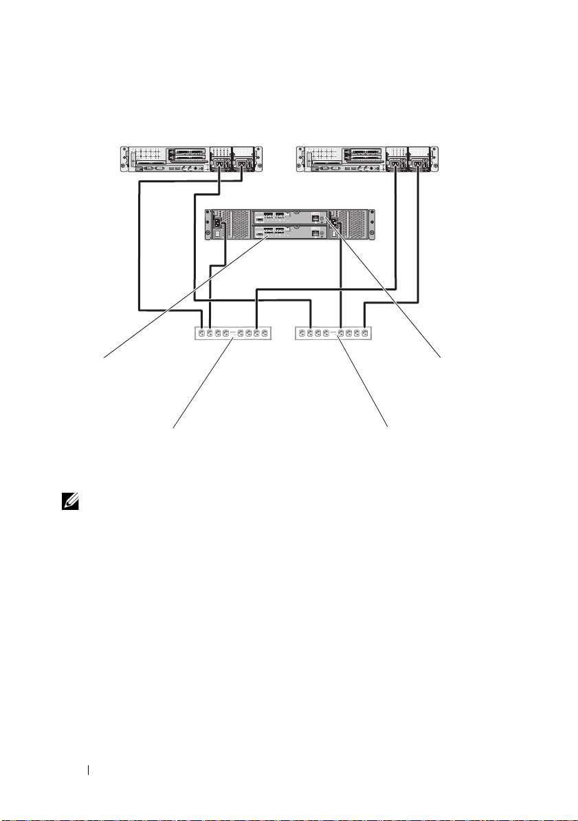
Figure 2-1. Power Cabling Example
primary power supplies on one AC
power strip [or one AC PDU (not
shown)]
redundant power supplies on one AC
power strip [or one AC PDU (not
shown)]
MD36x0f RAID
controller module 0
MD36x0f RAID
controller module 1
cluster node 1
cluster node 2
NOTE: This illustration is intended only to demonstrate the power distribution of the
components.
20 Cabling Your Cluster Hardware
Page 21

Cabling Your Public and Private Networks
The network adapters in the cluster nodes provide at least two network
connections for each node. These connections are described in Table 2-1.
Table 2-1. Network Connections
Network Connection Description
Public Network All connections to the client LAN.
At least one public network must be configured for
mixed mode (public mode and private mode) for
private network failover.
Private Network A dedicated connection for sharing cluster health and
status information between the cluster nodes.
Network adapters connected to the LAN can also
provide redundancy at the communications level in
case the cluster interconnect fails.
For more information on private network redundancy,
see your Microsoft Failover Clustering
documentation.
Figure 2-2 shows an example of network adapter cabling in which dedicated
network adapters in each node are connected to the public network and the
remaining network adapters are connected to each other (for the private
network).
Cabling Your Cluster Hardware 21
Page 22

Figure 2-2. Example of Network Cabling Connection
public network
p
u
b
l
i
c
n
e
t
w
o
r
k
a
d
a
p
t
e
r
private network
adapter
cluster node 1 cluster node 2
private network
Cabling Your Public Network
Any network adapter supported by a system running TCP/IP may be used to
connect to the public network segments. You can install additional network
adapters to support additional public network segments or to provide
redundancy in the event of a faulty primary network adapter or switch port.
Cabling Your Private Network
The private network connection to the cluster nodes is provided by a second
or subsequent network adapter that is installed in each node. This network is
used for intra-cluster communications.
Table 2-2 lists the required hardware components and connection method for
three possible private network configurations.
22 Cabling Your Cluster Hardware
Page 23

Table 2-2. Private Network Hardware Components and Connections
Method Hardware Components Connection
Network switch Gigabit or 10 Gigabit
Ethernet network
adapters and switches
Point-to-Point (two node
cluster only)
NOTE: Throughout this document, Ethernet refers to either Gigabit Ethernet or
10 Gigabit Ethernet.
Copper Gigabit or 10
Gigabit Ethernet network
adapters with RJ-45
connectors
Copper 10 Gigabit
Ethernet network
adapters with SFP+
connectors
Optical Gigabit or 10
Gigabit Ethernet network
adapters with LC
connectors
Depending on the hardware,
connect the CAT5e or CAT6
cables, the multimode optical
cables with Local Connectors
(LCs), or the twinax cables
from the network adapters in
the nodes to a switch.
Connect a standard CAT5e or
CAT6 Ethernet cable between
the network adapters in both
nodes.
Connect a twinax cable
between the network adapters
in both nodes.
Connect a multi-mode optical
cable between the network
adapters in both nodes.
Using Dual-Port Network Adapters for Your Private Network
You can configure your cluster to use the public network as a failover for
private network communications. However, if dual-port network adapters are
used, do not use two ports simultaneously to support both the public and
private networks.
Cabling Your Cluster Hardware 23
Page 24

NIC Teaming
Network Interface Card (NIC) teaming combines two or more NICs to
provide load balancing and/or fault tolerance. Your cluster supports NIC
teaming, but only in a public network; NIC teaming is not supported in a
private network.
NOTE: Use the same brand of NICs in a team. You cannot mix brands of teaming
drivers.
Cabling the Storage Systems
This section provides information on cabling your cluster to a storage system
in a direct-attached configuration or to one or more storage systems in a
SAN-attached configuration.
Cabling Storage for Your Direct-Attached Cluster
A direct-attached cluster configuration consists of redundant Fibre Channel
host bus adapter (HBA) ports cabled directly to a Dell PowerVault MD36x0f
storage system. If a component (for example, port, cable, or the storage
controller) fails in the storage path, the MPIO software automatically
re-routes the I/O requests to the alternate path so that the storage array
continues to operate without interruption. The configuration with two
single-port HBA provides higher availability. An HBA failure does not cause
the failover cluster to move cluster resources to the other cluster node.
Figure 2-3 shows an example of a direct-attached, single cluster configuration
with redundant HBA ports installed in each cluster node.
24 Cabling Your Cluster Hardware
Page 25
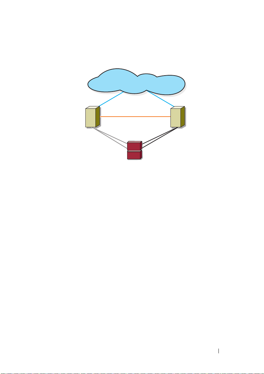
Figure 2-3. Direct-Attached Cluster Configuration
cluster node
private network
public network
cluster node
storage system
Fibre Channel
connections
Fibre Channel
connections
Cabling Your Cluster Hardware 25
Page 26

Cabling a Cluster to a Dell PowerVault MD36x0f Storage System
Each cluster node attaches to the storage system using two Fibre optic cables
with duplex local connector (LC) multimode connectors that attach to the
HBA ports in the cluster nodes and the MD36x0f RAID controller module
ports in the MD36x0f storage system. These connectors consist of two
individual Fibre optic connectors with indexed tabs that must be aligned
properly into the HBA ports and the MD36x0f RAID controller module.
CAUTION: Do not remove the connector covers until you are ready to insert the
connectors into the HBA port, MD36x0f RAID controller module port, or tape library
port.
Cabling a Two-Node Direct-Attached Cluster to an MD36x0f Storage System
1
Connect cluster node 1 to the storage system:
a
Install a cable from cluster node 1 HBA port 0 to the fibre channel
port on MD36
b
Install a cable from cluster node 1 HBA port 1 to the fibre channel
port on MD36
2
Connect cluster node 2 to the storage system:
a
Install a cable from cluster node 2 HBA port 0 to the fibre channel
port on MD36
b
Install a cable from cluster node 2 HBA port 1 to the fibre channel
port on MD36
x
0f RAID controller module 0, port In-0.
x
0f RAID controller module 1, port In-0.
x
0f RAID controller module 0, port In-1.
x
0f RAID controller module 1, port In-1.
26 Cabling Your Cluster Hardware
Page 27
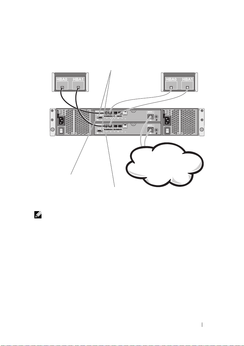
Figure 2-4. Cabling a Two-Node Direct-Attached Cluster to a PowerVault MD36x0f
Corporate, public, or
private network
cluster node1
cluster node2
SAS out port (2)
RAID controller module 0
RAID controller module 1
Storage System
NOTE: The SAS out port provides SAS connection for cabling to MD1200 or
MD1220 expansion enclosure(s).
Cabling a Four-Node Direct-Attached Cluster to an MD36x0f Storage System
You can configure a cluster with more than two nodes in a direct-attached
configuration using a PowerVault MD36x0f storage system. The MD36x0f
storage system can support up to four-node direct-attached cluster.
The following example explains how to cable a four-node direct-attached
cluster:
1
Connect cluster node 1 to the storage system:
a
Install a cable from cluster node 1 HBA port 0 to the Fibre Channel
port on the MD36
x
0f RAID controller module 0, port In-0.
Cabling Your Cluster Hardware 27
Page 28

b
Install a cable from cluster node 1 HBA port 1 to the Fibre Channel
port on the MD36
2
Connect cluster node 2 to the storage system:
a
Install a cable from cluster node 2 HBA port 0 to the Fibre Channel
port on the MD36
b
Install a cable from cluster node 2 HBA port 1 to the Fibre Channel
port on the MD36
3
Connect cluster node 3 to the storage system:
a
Install a cable from cluster node 3 HBA port 0 to the Fibre Channel
port on the MD36
b
Install a cable from cluster node 3 HBA port 1 to the Fibre Channel
port on the MD36
4
Connect cluster node 4 to the storage system:
a
Install a cable from cluster node 4 HBA port 0 to the Fibre Channel
port on the MD36
b
Install a cable from cluster node 4 HBA port 1 to the Fibre Channel
port on the MD36
x
0f RAID controller module 1, port In-0.
x
0f RAID controller module 0, port In-1.
x
0f RAID controller module 1, port In-1.
x
0f RAID controller module 0, port In-2.
x
0f RAID controller module 1, port In-2.
x
0f RAID controller module 0, port In-3.
x
0f RAID controller module 1, port In-3.
28 Cabling Your Cluster Hardware
Page 29
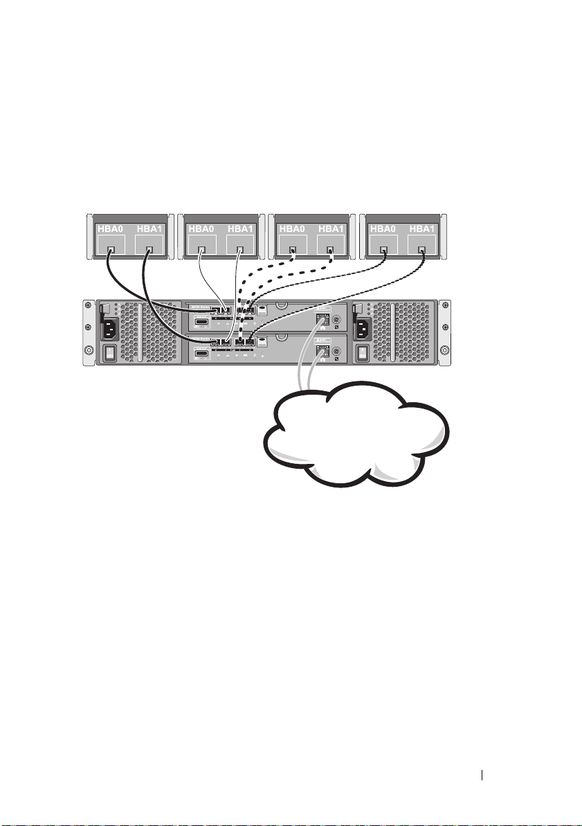
Figure 2-5 shows a four-cluster node connected to two RAID controller
PowerVault MD360x0f series storage array
Corporate, public, or
private network
modules. Since each cluster node has redundant paths, loss of a single path
still allows access to the storage array through the alternate path.
Figure 2-5. Cabling a Four-Node Direct-Attached Cluster to a PowerVault MD36x0f
Storage System
Cabling Multiple Clusters to an MD36x0f Storage System
The high number of available Fibre Channel ports on the
system also allows you to configure four-node clusters, 2 two-node clusters or
a mix of cluster(s) and non-clustered server(s) in a direct-attached
configuration.
Cabling Your Cluster Hardware 29
MD36x0f
storage
Page 30

Cabling Two Two-Node Direct-Attached Clusters to an MD36x0f Storage System
The following steps are an example of how to cable a two two-node cluster.
1
In the first cluster, connect cluster node 1 to the storage system:
a
Install a cable from cluster node 1 HBA port 0 to the Fibre Channel
port on the MD36
b
Install a cable from cluster node 1 HBA port 1 to the Fibre Channel
port on the MD36
2
In the first cluster, connect cluster node 2 to the storage system:
a
Install a cable from cluster node 2 HBA port 0 to the Fibre Channel
port on the MD36
b
Install a cable from cluster node 2 HBA port 1 to the Fibre Channel
port on the MD36
3
In the second cluster, connect cluster node 1 to the storage system:
a
Install a cable from cluster node 1 HBA port 0 to the Fibre Channel
port on the MD36
b
Install a cable from cluster node 1 HBA port 1 to the Fibre Channel
port on the MD36
4
In the second cluster, connect cluster node 2 to the storage system:
a
Install a cable from cluster node 2 HBA port 0 to the Fibre Channel
port on the MD36
b
Install a cable from cluster node 2 HBA port 1 to the Fibre Channel
port on the MD36
x
0f RAID controller module 0, port In-0.
x
0f RAID controller module 1, port In-0.
x
0f RAID controller module 0, port In-1.
x
0f RAID controller module 1, port In-1.
x
0f the RAID controller module 0, port In-2.
x
0f RAID controller module 1, port In-2.
x
0f RAID controller module 0, port In-3.
x
0f RAID controller module 1, port In-3.
Cabling Storage for Your SAN-Attached Cluster
A SAN-attached cluster is a cluster configuration where all cluster nodes that
are attached to a single storage system or to multiple storage systems through
SAN use a redundant switch fabric.
SAN-attached cluster configurations provide more flexibility, expandability,
and performance than direct-attached configurations.
For more information on Fibre Channel switch fabrics, see "Implementing
Zoning on a Fibre Channel Switched Fabric" on page 45.
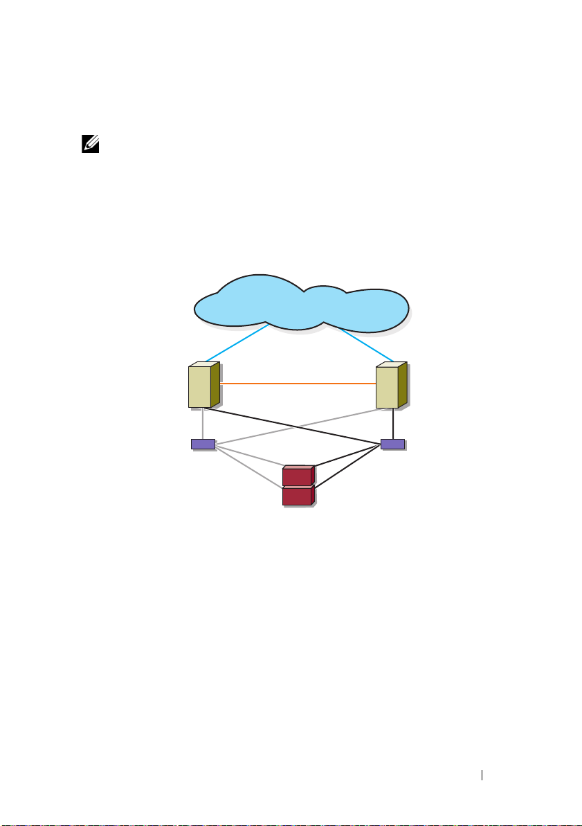
Figure 2-6 shows an example of a two node SAN-attached cluster.
Figure 2-7 shows an example of an sixteen-node SAN-attached cluster.
30 Cabling Your Cluster Hardware
Page 31
Similar cabling concepts can be applied to clusters that contain a different
cluster node
cluster node
private network
Fibre Channel
connections
storage system
Fibre Channel
switch
Fibre Channel
switch
public network
Fibre Channel
connections
number of nodes.
NOTE: The connections listed in this section are representative of one proven
method of ensuring redundancy in the connections between the cluster nodes and
the storage system. Other methods that achieve the same type of redundant
connectivity may be acceptable.
Figure 2-6. Two-Node SAN-Attached Cluster
Cabling Your Cluster Hardware 31
Page 32
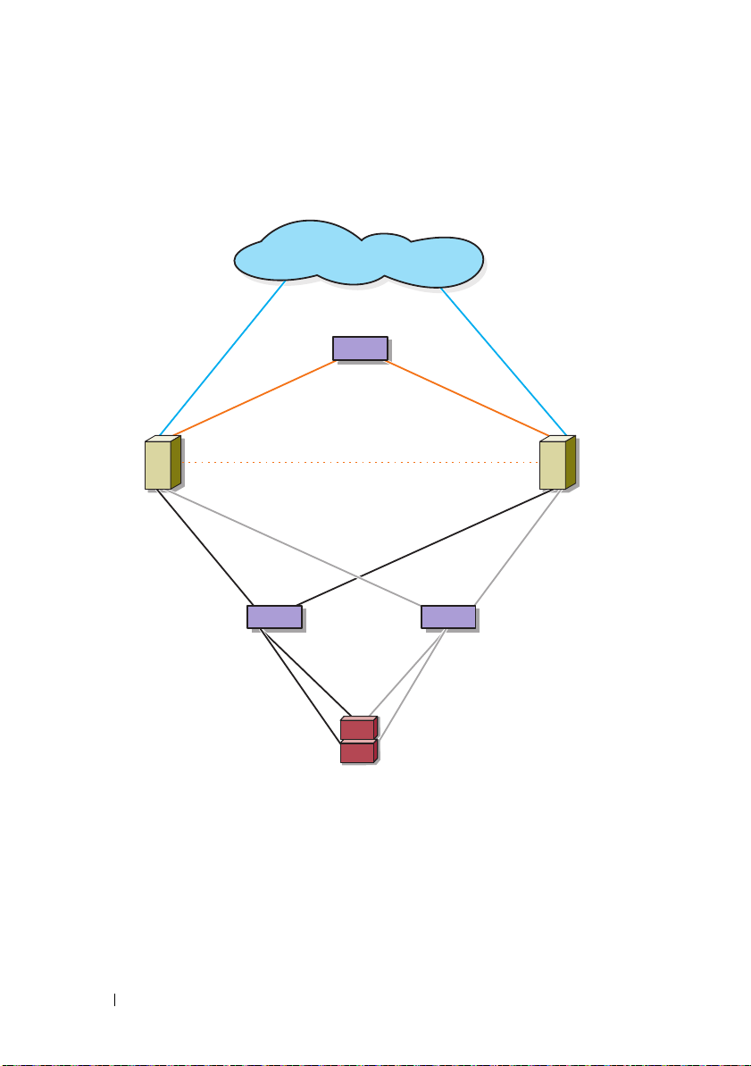
Figure 2-7. Sixteen-Node SAN-Attached Cluster
public network
storage system
cluster nodes (2-16)
Fibre Channel
switch
Fibre Channel
switch
private
network
32 Cabling Your Cluster Hardware
Page 33

Cabling a SAN-Attached Cluster to an MD36x0f Storage System
The cluster nodes attach to the storage system using a redundant switch
fabric and Fibre optic cables with duplex LC multimode connectors.
The switches, the HBA ports in the cluster nodes, and the RAID controller
module ports in the storage system use duplex LC multimode connectors.
The connectors consist of two individual fibre optic connectors with indexed
tabs that must be inserted and aligned properly in the small form-factor
pluggable (SFP) module connectors on the Fibre Channel switches and the
connectors on the cluster nodes and storage systems.
Each HBA port is cabled to a port on a Fibre Channel switch. One or more
cables connect from the outgoing ports on a switch to a RAID controller
module on an MD36x0f storage system.
NOTE: Adding more cables from the storage system to the switches can increase
the I/O bandwidth and high availability of data.
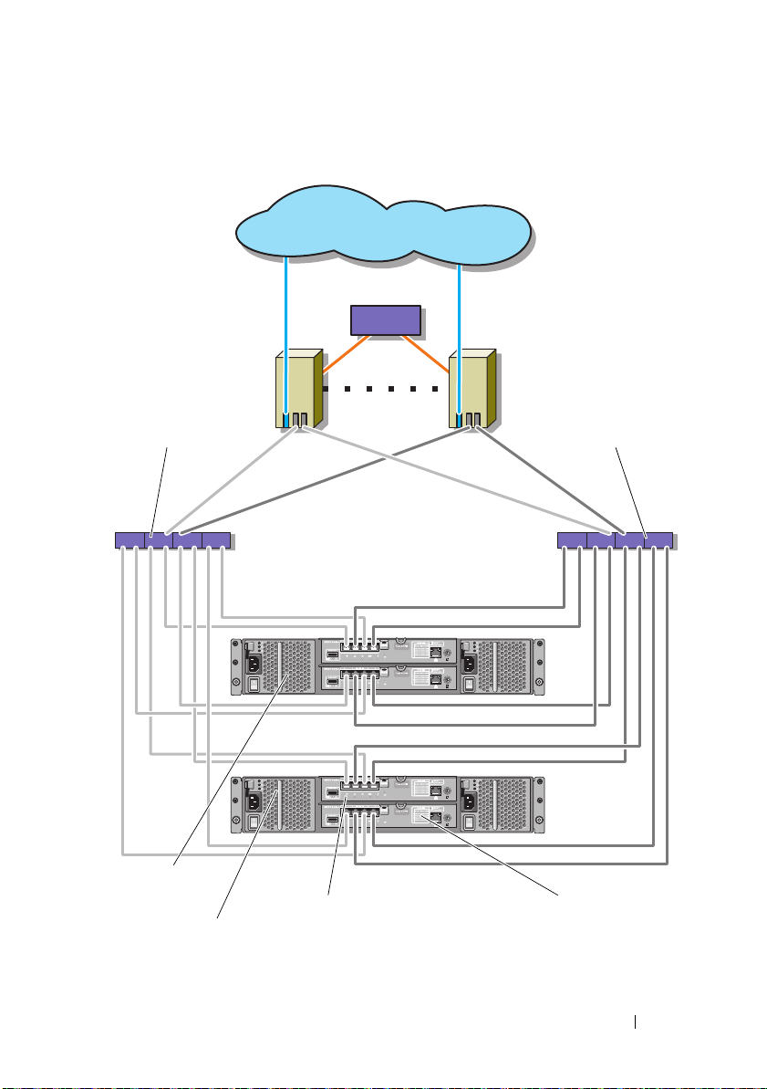
Figure 2-8 illustrates a method for cabling a SAN-attached cluster to an
MD36x0f storage system.
Cabling a SAN-Attached Cluster to the MD36x0f Storage System
1
Connect cluster node 1 to the SAN:
a
Connect a cable from HBA port 0 to the Fibre Channel switch (Switch
fabric A).
b
Connect a cable from HBA port 1 to the Fibre Channel switch (Switch
fabric B).
2
Repeat step 1 for each additional cluster node.
3
Connect the storage system to the SAN:
a
Connect a cable from Fibre Channel switch (Switch fabric A) to the
Fibre Channel port on the MD36
x
0f RAID controller module 1, port
In-1.
b
Connect a cable from Fibre Channel switch (Switch fabric A) to the
Fibre Channel port on the MD36
x
0f RAID controller module 1, port
In-3.
c
Connect a cable from Fibre Channel switch (Switch fabric A) to the
Fibre Channel port on the MD36
x
0f RAID controller module 0, port
In-0.
Cabling Your Cluster Hardware 33
Page 34

d
Connect a cable from Fibre Channel switch (Switch fabric A) to the
Fibre Channel port on the MD36
x
0f RAID controller module 0, port
In-2.
e
Connect a cable from Fibre Channel switch (Switch fabric B) to the
Fibre Channel port on the MD36
x
0f RAID controller module 0, port
In-1.
f
Connect a cable from Fibre Channel switch 1 (Switch fabric B) to the
Fibre Channel port on the MD36
x
0f RAID controller module 0, port
In-3.
g
Connect a cable from Fibre Channel switch 1 (Switch fabric B) to the
Fibre Channel port on the MD36
x
0f RAID controller module 1, port
In-0.
h
Connect a cable from Fibre Channel switch 1 (Switch fabric B) to the
Fibre Channel port on the MD36
x
0f RAID controller module 1, port
In-2.
34 Cabling Your Cluster Hardware
Page 35
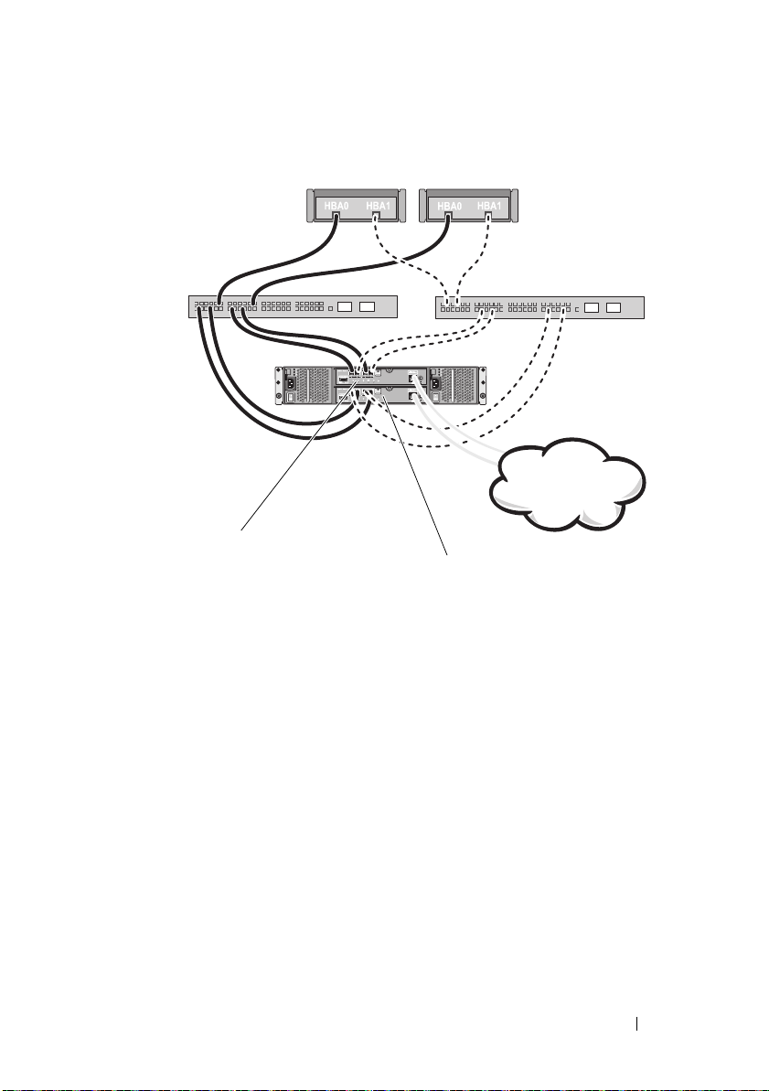
Figure 2-8. Cabling a SAN-Attached Cluster to the MD36x0f
cluster node 1
cluster node 2
switch fabric A
switch fabric B
corporate, public,
or private network
RAID controller module 0
RAID controller module 1
Cabling Your Cluster Hardware 35
Page 36

Table 2-3. Zoning Configuration Information
Switch Fabric A Switch Fabric B
Zone_1_Cluster Node_1_HBA_0 Zone_3_Cluster Node_1_HBA_1
Cluster Node_1_HBA_0 Cluster Node_1_HBA_1
Array_Ctrl-0-0 Array_Ctrl-0-1
Array_Ctrl-0-2 Array_Ctrl-0-3
Array_Ctrl-1-1 Array_Ctrl-1-0
Array_Ctrl-1-3 Array_Ctrl-1-2
Zone_2_Cluster Node_2_HBA_0 Zone_4_Cluster Node_2_HBA_1
Cluster Node_2_HBA_0 Cluster Node_2_HBA_1
Array_Ctrl-0-0 Array_Ctrl-0-1
Array_Ctrl-0-2 Array_Ctrl-0-3
Array_Ctrl-1-1 Array_Ctrl-1-0
Array_Ctrl-1-3 Array_Ctrl-1-2
Cabling Multiple SAN-Attached Clusters to an MD36x0f Storage System
To cable multiple clusters to the storage system, connect the cluster nodes to
the appropriate Fibre Channel switches and then connect the Fibre Channel
switches to the appropriate MD36x0f RAID controller modules.
For rules and guidelines for SAN-attached clusters, see the Dell Cluster
Configuration Support Matrices at dell.com/ha.
Connecting a PowerEdge Cluster to a Tape Library
To provide additional backup for your cluster, you can add tape backup devices
to your cluster configuration. The Dell PowerVault tape libraries may contain
an integrated Fibre Channel bridge or Storage Network Controller (SNC) that
connects directly to your Fibre Channel switch.
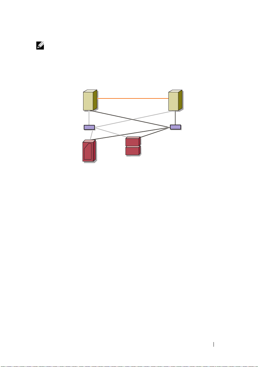
Figure 2-9 shows a supported Failover Cluster configuration using redundant
Fibre Channel switches and a tape library. In this configuration, each of the
cluster nodes can access the tape library to provide backup for your local disk
resources, as well as your cluster disk resources. This configuration allows you
to add more servers and storage systems in the future, if needed. For more
information on configuring these components, see the storage and tape
backup documentation at support.dell.com/manuals.
36 Cabling Your Cluster Hardware
Page 37
NOTE: While tape libraries can be connected to multiple fabrics, they do not
cluster node
tape library
storage system
cluster node
private network
Fibre Channel
switch
Fibre Channel
switch
provide path failover.
Figure 2-9. Cabling a Storage System and a Tape Library
Cabling Your Cluster Hardware 37
Page 38

Connecting a PowerEdge Cluster to Multiple PowerVault MD3600f or MD3620f Storage Systems
You can increase your cluster storage capacity by attaching multiple storage
systems to your cluster using redundant Fibre Channel switch fabrics. The
PowerEdge cluster systems support configurations with multiple PowerVault
MD3600f or MD3620f storage systems attached to clustered systems. In this
scenario, the Failover Cluster software can fail over disk drives in any clusterattached shared storage system between the cluster nodes.
38 Cabling Your Cluster Hardware
Page 39
public network
private network
2 to 16 cluster
nodes
switch fabric A
MD36x0f RAID
controller module 0
MD36x0f RAID
controller module 1
storage array 1
storage array 2
switch fabric B
Figure 2-10. SAN-Attached Cluster Configuration With Multiple Storage Arrays
Cabling Your Cluster Hardware 39
Page 40

When attaching multiple PowerVault MD3600f and MD3620f storage
systems with your cluster, the following rules apply:
• A maximum of four Power Vault
MD3600f and MD3620f
storage systems
per cluster.
• The shared storage systems and firmware must be identical. Using
dissimilar storage systems and firmware for your shared storage is not
supported.
• Microsoft Windows limits access to drives using limited drive letters which
is 22. A maximum of 22 drive letters (E to Z) can be used for your storage
system disks.
NOTE: Drive letters A through D are reserved for local disks.
• Windows Server 2008 Enterprise Edition supports mount points, allowing
greater than 22 drives per cluster.
40 Cabling Your Cluster Hardware
Page 41

Preparing Your Systems for Clustering
CAUTION: Only trained service technicians are authorized to remove and access
any of the components inside the system. See the safety information that shipped
with your system for complete information about safety precautions, working
inside the system, and protecting against electrostatic discharge.
Cluster Configuration Overview
1
Ensure that your site can handle the cluster’s power requirements.
Contact your sales representative for information about your region's
power requirements.
2
Install the servers, the shared storage array(s), and the interconnect
switches (for example, in an equipment rack), and ensure that all these
components are turned on.
NOTE: For more information on step 3 through step 7 and step 10 through
step 12, see the “Preparing your systems for clustering” section of the
Dell Failover Clusters with Microsoft Windows Server 2008 Installation and
Troubleshooting Guide at support.dell.com/manuals.
3
Deploy the operating system (including any relevant service pack and
hotfixes), network adapter drivers, and storage adapter drivers (including
the MPIO software) on each of the servers that must become cluster
nodes. Depending on the deployment method that is used, it may be
necessary to provide a network connection to successfully complete
this step.
3
NOTE: You can record the Cluster configuration to the Cluster Data Form to
help in planning and deployment of your cluster. For more information, see the
"Cluster Data Form" on page 73 and "Zoning Configuration Form" on page 77.
4
Establish the physical network topology and the TCP/IP settings for
network adapters on each server node to provide access to the cluster
public and private networks.
Preparing Your Systems for Clustering 41
Page 42

5
Configure each server node as a member server in the same Windows
Active Directory Domain.
NOTE: You can configure the cluster nodes as Domain Controllers. For more
information, see the “Selecting a Domain Model” section of the Dell Failover
Clusters with Microsoft Windows Server 2008 Installation and
Troubleshooting Guide at support.dell.com/manuals.
6
Establish the physical storage topology and any required storage network
settings to provide connectivity between the storage array and the servers
that must be configured as cluster nodes. Configure the storage system(s)
as described in your storage system documentation.
7
Use storage array management tools to create at least one logical unit
number (LUN). The LUN is used as a witness disk for Microsoft Windows
Server 2008 Failover cluster. Ensure that this LUN is presented to the
servers that must be configured as cluster nodes.
NOTE: It is recommended that you configure the LUN on a single node, for
security reasons, as mentioned in step 8 when you are setting up the cluster.
Later, you can configure the LUN as mentioned in step 9 so that other cluster
nodes can access it.
8
Select one of the systems and form a new failover cluster by configuring
the cluster name, cluster management IP, and quorum resource. For more
information, see "Preparing Your Systems for Clustering" on page 41.
NOTE: For Windows Server 2008 Failover Clusters, run the Cluster Validation
Wizard to ensure that your system is ready to form the cluster.
9
Join the remaining node(s) to the failover cluster. For more information,
see "Preparing Your Systems for Clustering" on page 41.
10
Configure roles for cluster networks. Take any network interfaces that are
used for other purposes outside of the cluster and out of the control of the
cluster.
42 Preparing Your Systems for Clustering
Page 43

11
Test the failover capabilities of your new cluster.
NOTE: You can also use the Cluster Validation Wizard.
12
Configure highly-available applications and services on your failover
cluster. Depending on your configuration, this may also require providing
additional LUNs to the cluster or creating new cluster resource groups.
Test the failover capabilities of the new resources.
13
Configure client systems to access the highly available applications and
services that are hosted on your failover cluster.
Installation Overview
Each node in your Dell Windows Server failover cluster must have the same
release, edition, service pack, and processor architecture of the Windows
Server operating system installed. For example, all nodes in your cluster may
be configured with Windows Server 2008 R2, Enterprise x64 Edition. If the
operating system varies among nodes, it is not possible to configure a failover
cluster successfully. It is recommended to establish system roles prior to
configuring a failover cluster, depending on the operating system configured
on your cluster.
For a list of recommended operating systems, hardware components, and
driver or firmware versions for your Dell Windows Server Failover Cluster,
see the Dell Cluster Configuration Support Matrices at dell.com/ha.
For more information on deploying your cluster with the Windows Server
2008 operating systems, see the Dell Failover Clusters with Microsoft Windows
Server 2008 Installation and Troubleshooting Guide at
support.dell.com/manuals.
Preparing Your Systems for Clustering 43
Page 44

The following sub-sections describe steps that enable you to establish
communication between the cluster nodes and your shared MD3600f or
MD3620f storage array(s), and to present disks from the storage array to the
cluster:
1
Installing Supported Fibre Channel HBAs
2
Implementing Zoning on a Fibre Channel Switched Fabric
3
Installing the Storage Management Software
4
Configuring the Shared Storage System
5
Configuring a Failover Cluster
Installing Supported Fibre Channel HBAs
The storage array supports a specific set of Fibre Channel HBAs, each
requiring a unique driver and firmware level. For more information on
supported HBAs with the drivers, firmware, and BIOS versions, see the Dell
Cluster Configuration Support Matrices at dell.com/ha.
If an HBA is already installed on your host server, verify that it is listed in the
Support Matrices and operates at the driver and/or firmware level specified. If
the HBA is not listed in the Support Matrices, it should not be used to
connect to the storage array.
CAUTION: Connecting the storage array to a non-supported host server HBA or
installing non-qualified HBA drivers or firmware can cause instability or loss of
access to your data.
Installing Fibre Channel HBA on Your Host Server
For instructions about physically installing an HBA in your host server and
loading supported drivers and firmware, see the documentation supplied with
your HBA hardware.
Customizing HBA Drivers and Firmware Settings
In most cases, the default manufacturer HBA driver and firmware settings are
sufficient to support Fibre Channel communication with the storage array.
44 Preparing Your Systems for Clustering
Page 45

However, in the case of certain HBA manufacturers, the Dell Cluster
Configuration Support Matrices at dell.com/ha may contain information
about specific driver and firmware settings necessary to optimize storage
arrays. Review the Support Matrices to ensure that you are aware of any
customized settings that may affect the performance of your HBA.
NOTE: Most Fibre Channel HBAs require a link timeout and node timeout value of
10 seconds. This value can be set using the HBA manufacturer's management
utilities, for example, Emulex's OneCommand Manager and QLogic's Enterprise
Fabric Suite.
For more information about installing and configuring HBAs, see the
following:
•
Emulex HBAs
Support website at
• QLogic HBAs—QLogic support website at
website at
• Brocade HBAs—Brocade support website at
Support website at
For more information about supported HBA controllers and drivers, see the
Dell Cluster Configuration Support Matrices at dell.com/ha.
—Emulex support website at
support.dell.com
support.dell.com
support.dell.com
.
.
.
emulex.com
qlogic.com
brocade.com
or the Dell
or the Dell Support
or the Dell
Implementing Zoning on a Fibre Channel Switched Fabric
A Fibre Channel switch allows you to connect multiple devices to the SAN
without compromising bandwidth or data throughput. Switch zoning
implemented on each Fibre Channel switch hardware component using the
manufacturer’s embedded utility, allows you to divide port traffic between
the host server and storage array to maintain the highest level of redundancy.
Figure 2-8 shows each connection to the cluster node routed to an individual
logical zone on the SAN. Two physical switches provide an alternate
(redundant) data path to the storage array. If a single HBA, switch or RAID
controller fails, the host server can still access data on the storage array
through one of the alternate paths provided by the switches.
NOTE: For a list of supported Fibre Channel switches, see the Dell Cluster
Configuration Support Matrices at dell.com/ha.
Preparing Your Systems for Clustering 45
Page 46

World Wide Name Zoning
There are several different switch zoning techniques used across various
SANs. When configuring zoning with your storage array, use 64 bit World
Wide Name (WWN) port zoning to uniquely identify each component in
your Fibre Channel switch fabric. An advantage of using WWN port zoning
(also called soft zoning) is that it allows you to remove and/or replace cabling
to and from the fabric without reconfiguring the existing zone logic.
When implemented on the Fibre Channel switch, port WWN zoning causes
the host server to query the World Wide Identifier (WWID) name of all
attached physical disks and/or expansion enclosures each time it access the
switch fabric. By zoning specific ports on the host server, switch and storage
array together, the switch allows the host server to see only devices included in
that zone, decreasing the amount of time it would otherwise take for the host
server to query attached, but out-of-zone, devices.
Switch Zoning Requirements
The storage array imposes specific requirements that must be followed when
setting up Fibre Channel switch zoning:
• If a Fibre Channel switch is used to connect your host server and storage
array, it must be zoned. Un-zoned or open switches cannot be used.
• Always use WWN port zoning, not
based on the device.
• No more than one HBA may be connected to a single logical switch zone.
• No more than four paths (port-to-port segments) can be established from
a single, physical host server to a single RAID controller.
• A zone can contain multiple targets.
• A zone can span multiple storage arrays.
• If the Remote Replication premium feature is activated, a separate zone
for each replication port is required. Only data traffic related to Remote
Replication can move through that zone. For more details and
requirements regarding Remote Replication, see the
support.dell.com/manuals
.
hard zoning
that blocks or grants access
Owner’s Manual
at
46 Preparing Your Systems for Clustering
Page 47

Setting Up Zoning on the Fibre Channel Switch Hardware
Setting up zoning on Fibre Channel switches varies greatly between
manufacturers. For detailed information on how to set up zoning on your
switch, see the manufacturer’s product documentation or technical support
website.
Table 3-1 provides a list of WWN identifiers that you can find in the Dell
PowerVault MD36x0f cluster environment.
Table 3-1. Port Worldwide Names in a SAN Environment
Identifier Description
xx:xx:xx:2b:xx:xx:xx:xx PowerVault MD36x0f RAID controller module
xx:xx:00:00:C9:xx:xx:xx Emulex HBA ports
xx:xx:00:E0:8B:xx:xx:xx QLogic HBA ports (non-embedded)
xx:xx:00:0F:1F:xx:xx:xx Dell 2362M HBA port
xx:xx:xx:60:45:xx:xx:xx PowerVault 132T and 136T tape libraries
xx:xx:xx:E0:02:xx:xx:xx PowerVault 128T tape autoloader
xx:xx:xx:C0:01:xx:xx:xx PowerVault 160T tape library and Fibre
Channel tape drives
xx:xx:xx:C0:97:xx:xx:xx PowerVault ML6000 Fibre Channel tape drives
CAUTION: When you replace a Fibre Channel HBA in a PowerEdge server,
reconfigure your zones to provide continuous client data access. Additionally,
when you replace a switch module, reconfigure your zones to prevent data loss or
corruption.
Installing the Storage Management Software
The PowerVault MD3600f and MD3620f storage software installer provides
features that include the core software, providers, and optional utilities. The
core software feature includes the host-based storage agent, MPIO software,
and MDSM application used to configure, manage and monitor the storage
array solution. The providers feature includes a provider for the Microsoft
Virtual Disk Service (VDS) and Microsoft Volume Shadow-Copy Service
(VSS) frameworks.
Preparing Your Systems for Clustering 47
Page 48

NOTE: For more information about the Microsoft VDS, Microsoft VSS providers,
see the Dell PowerVault MD3600f and MD3620f Storage Arrays Owner's Manual.
Follow these steps to install the Storage Management Software:
1
Close all other programs before installing any new software.
2
Insert the PowerVault MD36x0f resource media.
Depending on the outrun settings of the operating system, the
PowerVault MD36
prompt may be displayed to run the
PowerVault MD launcher is not displayed and there is no prompt to run
the
md_launcher.exe
run the
3
Select
4
Select one of the following installation options:
• Full (recommended)—This package installs core software, providers,
• Host Only—This package includes the host-based storage agent,
• Management Station—This package includes the MD Storage
• Custom—This option allows you to select specific components.
• Reboot each host server.
md_launcher.exe
Install MD36x0f Storage Software
and utilities. It includes the necessary host-based storage agent, MPIO
software, MD Storage Manager, providers, and optional utilities.
MPIO software, and optional utilities required to configure the host.
Manager, providers, and optional utilities.
x
0f Resource DVD
file, navigate to the root of the resource media and
file.
window may be displayed or a
md_launcher.exe
.
file. If the
Dell
Configuring the Shared Storage System
See Table 1-2 for a list of supported Dell Powervault MD36x0f storage
systems. Before you begin configuring your storage system, you must fill out
the "Zoning Configuration Form" on page 77. Gathering this type of
information about your cluster node, HBAs, and storage before starting the
configuration steps helps you complete the process faster.
48 Preparing Your Systems for Clustering
Page 49

Automatic Storage Array Discovery
1
Launch MDSM.
The
Enterprise Management
Management
•
Devices
•
Setup
window contains the following tabs:
tab—Provides information about the storage arrays.
tab—Presents the initial setup tasks that guide you through
window opens. The
Enterprise
adding storage arrays and configuring alerts.
If this is the first storage array to be set up, the
Add New Storage Array
window appears.
2
Select
Automatic
and click OK.
It may take several minutes for the discovery process to complete.
You can manage the array by launching the
from the
Enterprise Management
window. The
Array Management
Array Management
window
window provides management functions for a single storage array. You can
have multiple
Array Management
windows open simultaneously to
manage different storage arrays.
To launch the
Enterprise Management
Array Management
window, and double-click on the relevant storage
window, click on the
Devices
tab from
array.
Defining a Host
If the Host Context Agent is running on the host, the hosts and the host ports
connected to the storage array are automatically detected by MDSM and
appear in the Mappings tab in the Array Management window, under the
Default Group.
After the storage software is installed, all the hosts should show up. If one
host is not detected, it can be manually added:
1
In the
Array Management
window, select the
Mappings
tab and select the
appropriate storage array.
2
Perform the following actions:
a
Select
b
Select the
c
Select the
MappingsDefineHost
Setup
tab and click
Mappings
tab.
.
Manually Define Hosts
.
Preparing Your Systems for Clustering 49
Page 50

d
Right-click the root node (storage array name),
or
Host Group
the host, and select
The
Specify Host Name
3
In
Host name
4
Select the relevant option in
the this storage array
The
Specify Host Port Identifiers
5
Select the relevant option to add a host port identifier to the host, you can
node in the
Define Host
To po l og y
pane to which you want to add
from the pop-up menu.
window is displayed.
, enter an up to 30 character alphanumeric name.
Do you plan to use the storage partitions in
, and click
Next
.
window is displayed.
Default Group
select:
•
Add by selecting a known unsolicited host port identifier
unsolicited host port identifiers
, select the relevant host port
—In
identifier.
•
Add by creating a new host port identifier
identifier
, enter a 16-character name and an
identifier (up to 30 characters only), and click
NOTE: The host port identifier name must contain only the letters A through F.
6
Click
Next
.
The
Specify Host Type
7
In
Host
type, select the relevant operating system for the host.
The
Host Group Question
window is displayed.
window is displayed.
—In
New host port
Alias
for the host port
Add
.
node,
Known
8
Yo u ca n s el e ct :
•
Yes
—this host shares access to the same virtual disks with other hosts.
•
No
—this host does NOT share access to the same virtual disks with
other hosts.
9
Click
Next
.
If you select
select
10
Enter the name of the host group or select an existing host group and click
Next
.
The
Preview
Yes
, the
No
, go to step 11.
window is displayed.
Specify Host Group
window is displayed. If you
50 Preparing Your Systems for Clustering
Page 51

11
Click
Finish
.
Creating a Host Group
A host group is a logical entity of two or more hosts that share access to
specific virtual disks on the storage array.
To create host groups:
1
In the
Array Management window
2
In the
To po l og y
3
Perform one of the following actions:
• Select
pane, select the storage array or the default group.
Mappings Define Host Group
• Right-click the storage array or
Host Group
4
Type the name of the new host group in the
from the pop-up menu.
, select the
Mappings
.
Default Group
Enter New Host Group Name
tab.
and select
Define
field.
5
Select the appropriate hosts in the
Add
.
6
Click OK. The host group is added to the storage array.
Creating Disk Groups and Virtual Disks
Select Hosts to Add Area
field and click
In some cases, the virtual disks may have been bound when the system was
shipped. However, it is important that you install the management software
and verify that the desired virtual disk configuration exists.
You can manage your virtual disks remotely using PowerVault Modular Disk
Storage Manager. A minimum of one virtual disk is required for an
active/passive cluster configuration and at least two virtual disks are required
for an active/active cluster configuration.
Disk groups are created in the non-configured capacity of a storage array and
virtual disks are created in the free capacity of a disk group. The hosts
attached to the storage array read and write data to the virtual disks.
NOTE: Before you create virtual disks, you must first organize the physical disks
into disk groups and configure host access. You can then create virtual disks within
a disk group.
Preparing Your Systems for Clustering 51
Page 52

To create a virtual disk, use one of the following methods:
• Automatic configuration
• Manual configuration
Create disk groups using automatic configuration as follows:
1
To start the
• To create a disk group from unconfigured capacity in the storage
array—On the
Disk Group Create
Alternatively, you can right-click the
and select
• To create a disk group from unassigned physical disks in the storage
array—On the
disks of the same physical disk type, and select
Alternatively, you can right-click the unassigned physical disks, and
select
Create Disk Group Wizard
Logical
Create Disk Group
Physical
Create Disk Group
tab, select
.
from the pop-up menu.
tab, select one or more unassigned physical
from the pop-up menu.
, perform one of these actions:
Unconfigured Capacity
Unconfigured Capacity
Disk Group Create
node
node
.
• To create a secure disk group—On the
unassigned security capable physical disks of the same physical disk
type, and select
Alternatively, you can right-click the unassigned security capable
physical disks, and select
The
Create Disk Group
2
Click
Next
. The
displayed.
3
Type a name (up to 30 characters) for the disk group in
field.
4
Select the appropriate configuration method of Physical Disk selection
from the following:
• Automatic (see step 6)
• Manual (see step 7)
5
Click
Next
.
6
For automatic configuration, the
displayed.
52 Preparing Your Systems for Clustering
Disk Group Create
Create Disk Group
window is displayed.
Disk Group Name and Physical Disk Selection
RAID Level and Capacity
Physical
.
tab, select one or more
from the pop-up menu.
Disk Group Name
window is
window is
Page 53

a
Select the appropriate RAID level in the
Select Raid Level
can select RAID levels 0, 1/10, 6, and 5. Depending on your RAID level
selection, the physical disks available for the selected RAID level is
displayed in the
b
In the
Select Capacity
and click
7
For manual configuration, the
Select Capacity
Finish
.
table.
table, select the relevant disk group capacity
Manual Physical Disk Selection
displayed.
a
Select the appropriate RAID level in Select RAID level. You can select
RAID levels 0, 1/10, 6, and 5. Depending on your RAID level selection,
the physical disks available for the selected RAID level is displayed in
Unselected Physical Disks
b
In the
Unselected Physical Disks
disks and click
NOTE: You can select multiple physical disks at the same time by holding
<Ctrl> or <Shift> and selecting additional physical disks.
8
Click
Calculate Capacity
9
Click
Finish
Add
. A message is displayed confirming that the disk group is
table.
table, select the appropriate physical
.
to view the capacity of the new disk group.
successfully created and that you must create at least one virtual disk
before you can use the capacity of the new disk group.
To create virtual disks:
1
Choose one of these methods to start the
Create Virtual Disk Wizard
• To create a virtual disk from unconfigured capacity in the storage
array—On the
select
Virtual Disk Create
Logical
tab, select an unconfigured capacity node and
.
Alternatively, right-click the unconfigured capacity node and select
Create Virtual Disk
from the pop-up menu.
field. You
window is
:
• To create a virtual disk from free capacity on a disk group—On the
Logical
Create
Alternatively, right-click the free capacity
Virtual Disk
tab, select a free capacity node and select
.
node and select
from the pop-up menu.
Preparing Your Systems for Clustering 53
Virtual Disk
Create
Page 54

• To create a virtual disk from unassigned physical disks in the storage
array—On the
disks of the same physical disk type, and select
Physical
tab, select one or more unassigned physical
Virtual Disk Create
Alternatively, right-click the unassigned physical disks, and select
Create Virtual Disk
• To create a secure virtual disk—On the
from the pop-up menu.
Physical
tab, select one or
more unassigned security capable physical disks of the same physical
disk type, and select
Virtual Disk Create
.
Alternatively, you can right-click the unassigned security capable
physical disks and select
Create Virtual Disk
from the pop-up menu.
If you chose an unconfigured capacity node or unassigned physical
disks to create a virtual disk:
a
On the
b
Create a disk group by using the
The
Disk Group Required
window, click
Create Virtual Disk Wizard
Yes
.
Create Disk Group Wizard
is displayed after you create the
disk group.
If you chose a free capacity node, the
Create Virtual Disk
window is
displayed.
2
Click
Next
. The
Specify Capacity/Name
3
Select the appropriate unit for memory from the
enter the capacity of the virtual disk in the
window is displayed.
Units
drop-down list and
New Virtual Disk Capacity
field.
4
Enter a character name (up to 30 characters) for the virtual disk in the
Virtual Disk Name
5
In the
Advanced Virtual Disk Parameters
field.
field, you can select:
• Use recommended settings
• Customize settings
6
Click
Next
.
7
In the
Customize Advanced Virtual Disk Parameters
window, select the
appropriate Virtual Disk I/O Characteristics type from the following
options:
• File system (typical)
• Database
.
.
54 Preparing Your Systems for Clustering
Page 55

• Multimedia
•Custom
NOTE: If you select Custom, you must select an appropriate segment size.
8
Select the appropriate Preferred RAID controller module.
For more information on creating disk groups and virtual disks, see the Dell
PowerVault Modular Disk Storage Manager User’s Guide at
support.dell.com/manuals.
It is recommended that you create at least one virtual disk for each
application. If multiple NTFS volumes are created on a single virtual disk
using Windows Disk Management, the volumes failover together, rather than
individually from node-to-node.
NOTE: It is recommended that you use a RAID level other than RAID 0 (which is
commonly called striping). RAID 0 configurations provide very high performance,
but do not provide the level of availability required for the quorum resource. See the
documentation for your storage system for more information about setting up RAID
levels for the system.
Creating Host-to-Virtual Disk Mappings
Create host-to-virtual disk mappings to assign virtual disks to the host groups
containing cluster nodes as follows:
1
In the
2
Array Management
In the
To po l og y
pane, select:
window, select the
Mappings
tab.
•Default Group
• Undefined Mappings Node
• Individual Defined Mapping
• Host Group
•Host
3
In the tabular, select
Define Additional Mapping
4
Select the appropriate host group from the
5
In
Logical Unit Number
Mappings Define Additional Mapping
window is displayed.
Host Group
or
Host
field, select a LUN. The supported LUNs are 0
. The
field.
through 255.
Preparing Your Systems for Clustering 55
Page 56

6
Select the virtual disk to be mapped in the
Virtual Disk
section lists the names and capacity of the virtual disks that
Virtual Disk
section. The
are available for mapping based on the selected host group or selected
host.
7
Click
Add
.
NOTE: The Add button is inactive until a host group or host, LUN, and virtual disk
are selected.
8
To define additional mappings, repeat step 4 through step 7.
NOTE: After a virtual disk has been mapped once, it is no longer available in the
Virtual Disk area.
9
Click
Close
Mappings
. The mappings are saved. The
pane in the
Mappings
tab are updated to display the mappings.
To po l og y
pane and the
Defined
Troubleshooting Tools
The Dell PowerVault MDSM establishes communication with each managed
array and determines the current array status. When a problem occurs on a
storage array, the MDSM provides several ways to troubleshoot the problem.
Event Log
You can use the Event Log Viewer to view a detailed list of events that occur
in a storage array. The event log is stored on reserved areas on the storage array
disks. It records configuration events and storage array component failures.
CAUTION: Use this option only under the guidance of your Technical Support
representative.
The event log stores approximately 8000 events before it replaces an event
with a new event. If you want to keep a record of the events, you may save
them or clear them from the event log.
The Event Log window shows the following types of event views:
• Summary view—Shows an event summary in a table form.
• Detail view—Shows details about a selected event.
To view the event log:
1
In the
Array Management
View Event Log
. The
window, select
Event Log
Advanced Troubleshooting
is displayed. By default, the summary
view is displayed.
56 Preparing Your Systems for Clustering
Page 57

2
Select
View Details
to view the details of each selected log entry. A
Detail
pane is added to the event log that contains information about the log
item. You can view the details of a single log entry at a time.
3
To save the event log:
a
Click
4
5
Save As
b
Navigate to the relevant folder and enter the relevant file name.
c
Click
Save
Click
Clear All
Click
Close
. The
Save Events
dialog box is displayed.
.
to erase all log entries from the event log.
to exit the event log.
For more information, see the PowerVault Modular Disk Storage Manager
online help topics.
Recovery Guru
The Recovery Guru is a component of MDSM that diagnoses critical events
on the storage array and recommends step-by-step recovery procedures to
resolve problems.
To di s play t he Recovery Guru window in the
Array Management
window
,
perform one of the following actions:
•Click
•On the
• From the
Recovery Guru
Support
Attention
Status
.
.
tab, click
Recover from Failure
pane on the
Summary
tab, click
.
Storage Array Needs
You can detect a problem using the following indicators:
• Non-Optimal status icons
• Alert notification messages that are sent to the appropriate destinations
• Hardware indicator lights
The status icons return to Optimal status when problems are resolved.
Storage Profile
The storage array profile provides a description of all components and
properties of the storage array. The storage array profile also provides the
option to save the storage array profile information in a text file. You can also
Preparing Your Systems for Clustering 57
Page 58

use the storage array profile as an aid during recovery or as an overview of the
current configuration of the storage array. Create a new copy of the storage
array profile if your configuration changes.
1
To open the storage array profile in the
Array Management
window,
perform one of the following actions:
• Select
• Select the
Storage Array View Profile
Summary
tab and click
Storage Array Profile
.
in the
Status
area.
• Select the
The
Storage Array Profile
Support
tab and click
View Storage Array Profile
screen is displayed. The
.
Storage Array Profile
screen contains several tabs, and the title of each tab corresponds to the
subject of the information contained.
2
Perform one of these actions in the
Storage Array Profile
screen:
• View detailed information (Go to step 3).
• Search the storage array profile (Go to step 4).
• Save the storage array profile (Go to step 5).
• Close the storage array profile (Go to step 6).
3
Select one of the tabs, and use the horizontal scroll bar and the vertical
scroll bar to view the storage array profile information. You can use other
steps in this procedure to search the storage array profile, to save the
storage array profile, or to close the storage array profile.
4
To search the storage array profile:
a
Click
Find
.
b
In the
Find
text box, type the term that you want to search. If the
term is located on the current tab, it is highlighted in the storage array
profile information.
NOTE: The search is limited to the current tab. If you want to search for the
term in other tabs, select the tab and click Find again.
Click
Find
c
5
To save the storage array profile:
a
Click
b
To save all sections of the storage array profile, select
again to search for additional occurrences of the term.
Save As
.
58 Preparing Your Systems for Clustering
All Sections
.
Page 59

c
To save information from particular sections of the storage array
profile, select the
Select Sections
option and click on the check boxes
corresponding to the sections that you want to save.
d
Select an appropriate directory.
e
In
File Name
field, type a file name of your choice. To associate the
file with a particular software application that opens it, specify a file
extension, for example
NOTE: The file is saved as ASCII text.
f
Click
Save
.
6
To exit the storage array profile, click
Status Icons
.text
.
Close
.
Status icons identify the six possible health status conditions of the storage
array. For every non-optimal status icon, use the Recovery Guru to detect and
troubleshoot the problem. The six possible health status conditions are
described below:
• Optimal—Every component in the managed array is in the desired
working condition.
• Needs Attention—A problem exists with the managed array that requires
intervention to correct it.
• Fixing—The
managed array is currently changing to an
Needs Attention
condition has been corrected and the
Optimal
status.
• Unresponsive—The storage management station cannot communicate
with the array, one controller, or both controllers in the storage array. Wait
at least five minutes for the storage array to return to an
Optimal
status
following a recovery procedure.
• Unsupported—The node is not supported by this version of MDSM.
• Software Unsupported—The storage array is running a level of software
that is no longer supported by MDSM.
Preparing Your Systems for Clustering 59
Page 60

Configuring the RAID Level for the Shared Storage Subsystem
The virtual disks in your shared storage subsystem must be configured into
disk groups or virtual disks using the Dell PowerVault MDSM software. All
virtual disks, especially if they are used for the quorum resource, must be
bound and must incorporate the appropriate RAID level to ensure high
availability.
NOTE: It is recommended that you use a RAID level other than RAID 0 (which is
called striping). RAID 0 configurations provide very high performance, but do not
provide the level of availability required for the quorum resource. See the
documentation for your storage system for more information about setting up RAID
levels for your system.
Windows Operating System and Dynamic Volumes
The Windows operating system does not support dynamic disks (upgraded
disks) or volumes as shared cluster storage. If the shared cluster storage is
configured as a dynamic disk, the Cluster Configuration wizard is not able to
discover the disks, preventing the cluster and network clients from accessing
the disks.
Assigning Drive Letters and Mount Points
A mount point is a drive attached to an empty folder on an NTFS volume. A
mount point functions the same as a normal drive but is assigned a label or
name instead of a drive letter. Using mount points, a cluster can support more
shared disks than the number of available drive letters.
The cluster installation procedure does not automatically add the mount
point into the disks managed by the cluster. To add the mount point to the
cluster, create a physical disk resource in the cluster resource group for each
mount point. Ensure that the new physical disk resource is in the same cluster
resource group and is dependent on the root disk (that is, the disk from which
the mount point is attached).
NOTE: When mounting a drive to an NTFS volume, do not create mount points from
the quorum resource or between the clustered disks and the local disks. Mount
points must be in the same cluster resource group and must be dependent on the
root disk.
60 Preparing Your Systems for Clustering
Page 61

Naming and Formatting Drives on the Shared Storage System
Each virtual disk being created in the PowerVault Modular Disk Storage
Manager becomes a physical disk in Windows Disk Management. For each
physical disk, perform the following:
• Write the disk signature
• Create the partition
• Assign the drive letter
• Format the partition with NTFS
CAUTION: The drive letters are manually assigned from the second node, the
shared disks are simultaneously accessible from both nodes. To ensure file system
integrity and prevent possible data loss before you install the Microsoft Failover
Clustering software, prevent any I/O activity to the shared drives by performing the
following procedure on one node at a time and ensuring that the other node is shut
down.
The number of drive letters required by individual servers in a cluster may
vary. It is recommended that the shared drives be named in reverse
alphabetical order beginning with the letter z. To assign drive letters and
format drives on the shared storage system, perform the following steps:
1
Turn off node 2 and open
2
Allow Windows to enter a signature on all new physical or logical drives.
NOTE: Do not upgrade or convert your disks to dynamic disks.
3
Locate the icon for the first unnamed, unformatted drive on the shared
storage system.
4
Right-click the icon and select
unformatted drives are not visible, verify the following:
• The zoning is correct (for
• The LUNs have been assigned to the hosts.
• The storage system is properly cabled to the servers.
5
In the dialog box, create a partition with the size of the entire drive (the
default) and then click
Disk Management
Create
from the submenu. If the
SAN-attached configuration
OK
.
on node 1.
s only)
NOTE: A virtual disk that is mapped or assigned from the storage system to a
cluster node(s) is represented as a physical disk within the Windows
operating system on each node. Microsoft Cluster allows only one node to
Preparing Your Systems for Clustering 61
Page 62

access a given physical disk resource at a time. Therefore, if a disk is
partitioned and contains multiple NTFS volumes, concurrent access to
different volumes is only possible from the cluster node controlling the
physical disk resource. If two NTFS volumes need to be controlled by different
nodes, these volumes must reside on separate disks.
6
Click
Yes
to confirm the partition.
7
With the mouse pointer on the same icon, right-click and select
Drive Letter and Path
8
Assign a drive letter to an NTFS volume or create a mount point.
from the submenu.
To assign a drive letter to an NTFS volume:
a
Click
Edit
and select the letter you want to assign to the drive (for
example, z).
b
Click OK.
c
Go to step 9.
To create a mount point:
a
Click
Add
.
b
Click
Mount
in the following empty NTFS folder.
c
Type the path to an empty folder on an NTFS volume, or click
to locate it.
d
Click OK.
e
Go to step 9.
9
Click
Yes
to confirm the changes.
10
Right-click the drive icon again and select
11
Under
Volume La b e l
, enter a descriptive name for the new volume; for
Format
from the submenu.
example, Disk_Z or Email_Data.
12
In the dialog box, change the file system to
and click
Start
.
NTFS
, select
Change
Browse
Quick Format
,
NOTE: The NTFS file system format is required for shared-disk resources
under Microsoft Cluster.
13
Click OK at the warning.
14
Click
OK
to acknowledge that the format is complete.
15
Click
Close
to close the dialog box.
62 Preparing Your Systems for Clustering
Page 63

16
Repeat step 3 through step 15 for each remaining drive.
17
Close
Disk Management
18
Turn off node 1.
19
Turn on node 2.
20
On node 2, open
21
Ensure that the drive letters for node 2 are correct and re-assign the
drive letters, if necessary. To re-assign the drive letters, repeat step 7
through step 9.
Disk Management
.
.
Using Advanced (Premium) PowerVault Modular Disk Storage Manager Features
PowerVault Modular Disk Storage Manager includes the following advanced
features:
• Snapshot Virtual Disk
•Virtual Disk Copy
• The High Performance Tier
• Remote Replication
To install and enable these premium features, you must purchase a feature
key file for each feature and specify the storage array that must host them. For
more information, see the Premium Feature Activation card that shipped along
with your Dell PowerVault MD3600f or MD3620f storage system.
These premium features increase the high availability for your cluster
solution. It is essential that you follow the instructions below to ensure proper
cluster operations.
Snapshot Virtual Disk
Snapshot Virtual Disk captures point-in-time images of a virtual disk for
backup, testing, or data processing without affecting the contents of the
source virtual disk. You can use either Simple Path or Advanced Path to
create a snapshot for your cluster disk. The Snapshot Virtual Disk can be
mapped to the primary node (the node owning the source disk) or the
secondary node (the node not owning the source disk) for backup, testing, or
data processing.
Preparing Your Systems for Clustering 63
Page 64
CAUTION: Avoid mapping the Snapshot Virtual Disk to more than one node in the
cluster at any point of time. The Snapshot Virtual Disk is not managed by Failover
Cluster Manager, so mapping the Snapshot Virtual Disk to the host group or both
nodes in the cluster may allow both nodes to access data concurrently and thus
cause data corruption.
You can use a Microsoft Volume Shadow-copy Service (VSS) application to
create and map snapshots. If you are using MDSM instead, you must follow
the procedures described below.
To map the Snapshot Virtual Disk to the primary node:
1
Use Host-to-Virtual Disk Mapping in the Modular Disk Storage Manager.
This ensures that a different disk signature is assigned properly to the
Snapshot Virtual Disk.
2
Use Windows Disk Management to re-scan for the Snapshot Virtual Disk,
assign the drive letter, and start accessing the drive.
NOTE: The disks may be re-scanned several times for the Snapshot Virtual
Disk to be detected by Windows Disk Management. If the Snapshot Virtual
Disk is not detected, wait for a few minutes and re-scan the disks. Repeat the
process until the Snapshot Virtual Disk is detected; do not reboot the server.
To map the Snapshot Virtual Disk to the secondary node (the node not
owning the source disk):
CAUTION: Attempts to map the Snapshot Virtual Disk to the secondary node, prior
to obtaining the signature from the primary node, may cause the operating system
to misidentify the Snapshot Virtual Disk as an existing system volume and that may
result in data loss or an inaccessible Snapshot Virtual Disk.
1
Map the Snapshot Virtual Disk to the primary node to ensure that the
snapshot is assigned a new disk signature.
2
Use Modular Disk Storage Manager to unmap the Snapshot Virtual Disk
from the primary node.
3
Map the Snapshot Virtual Disk to the secondary node and start accessing
it.
NOTE: For a cluster configuration with multiple Snapshot Virtual Disks, each virtual
disk must be mapped to the node owning the associated source disk first. The
primary node for a Snapshot Virtual Disk may not be the primary node for another
Snapshot Virtual Disk.
64 Preparing Your Systems for Clustering
Page 65

Virtual Disk Copy
Virtual Disk Copy generates a full copy of data from the source virtual disk to
the target virtual disk in a storage array. You can use Virtual Disk Copy to back
up data, copy data from disk groups that use smaller-capacity physical disks to
disk groups using greater-capacity physical disks, or restore Snapshot Virtual
Disk data to the source virtual disk.
To create a Virtual Disk Copy of a Microsoft Cluster shared disk:
1
Create a Snapshot Virtual Disk using the cluster shared disk as a source
disk.
2
Do not map that Snapshot Virtual Disk to any cluster node. Then, use
the newly created Snapshot Virtual Disk as the source disk for the
Virtual Disk Copy.
NOTE: When you attempt to create a Virtual Disk Copy of a Microsoft Cluster
shared disk directly, the operation fails and the following error is displayed:
The operation cannot complete because the selected
virtual disk is not a source virtual disk
candidate
.
If the cluster shared disk fails and you want to restore it from the target virtual
disk, use Failover Cluster Manager to change the status of the cluster group
containing the failed disk to offline. Use one of the following methods:
• Use Virtual Disk Copy to transfer the data from the target virtual disk to
the cluster shared disk.
• Unassign the cluster shared disk from the host group and map the target
virtual disk to the host group.
Remote Replication
Remote Replication is a storage array premium feature that provides online,
real-time replication of data between storage arrays. When this feature is
activated, a dedicated port (port 3) on each RAID controller is reserved
exclusively for Remote Replication traffic. No other data traffic is allowed on
that port until the Remote Replication feature is deactivated. A dedicated
zone on each Fibre Channel switch is also required. For cabling examples,
configurations, host bus adapter (HBA) installation and zoning, see
Configuring Fibre Channel with the Dell MD3600f Series Storage Array at
support.dell.com/manuals.
Preparing Your Systems for Clustering 65
Page 66

Configuring a Failover Cluster
You can configure the operating system services on your Windows Server
failover cluster after you have established the private and public networks and
assigned the shared disks from the storage array to the cluster nodes. The
procedures for configuring the failover cluster are different depending on the
Windows Server operating system you use.
For more i n f ormation on deploying your cluster, see the Dell Failover Clusters
with Microsoft Windows Server 2008 Installation and Troubleshooting Guide at
support.dell.com/manuals.
66 Preparing Your Systems for Clustering
Page 67

A
Troubleshooting
Table A-1 describes the general cluster problems, the probable causes, and
solutions for each problem.
Table A-1. General Cluster Troubleshooting
Problem Probable Cause Corrective Action
The nodes cannot
access the storage
system, or the cluster
software is not
functioning with the
storage system.
The storage system is not
cabled properly to the
nodes or the cabling
between the storage
components is incorrect.
One of the cables is faulty. Replace the faulty cable.
Host Group or Host-toVirtual Disk Mappings is
not created correctly.
Ensure that the cables are
connected properly from the
node to the storage system. For
more information, see "Cabling
Your Cluster Hardware" on
page 19.
Verify the following:
• Host Group is created and the
cluster nodes are added to the
Host Group.
• Host-to-Virtual Disk Mapping
is created and the virtual disks
are assigned to the Host Group
containing the cluster nodes.
Troubleshooting 67
Page 68

Table A-1. General Cluster Troubleshooting
Problem Probable Cause Corrective Action
One of the nodes takes
a long time to join the
cluster.
Or
One of the nodes fails
to join the cluster.
The node-to-node
network has failed due to
a cabling or hardware
failure.
Long delays in node-tonode communications
may be normal.
One or more nodes may
have the Internet
Connection Firewall
enabled, blocking Remote
Procedure Call (RPC)
communications between
the nodes.
(continued)
Check the network cabling.
Ensure that the node-to-node
interconnection and the public
network are connected to the
correct NICs.
Verify that the nodes can
communicate with each other by
running the ping command from
each node to the other node. Try
both the host name and
IP address when using the ping
command.
Configure the Internet
Connection Firewall to allow
communications that are
required by the Microsoft
Failover Clustering and the
clustered applications or services.
For more information, see the
Microsoft Knowledge Base article
KB883398 at
support.microsoft.com.
68 Troubleshooting
Page 69

Table A-1. General Cluster Troubleshooting
Problem Probable Cause Corrective Action
Attempts to connect
to a cluster using
Failover Cluster
Manager fail.
• The Cluster
Service has not
been started.
• A cluster has not
(continued)
Verify that Cluster Service is
running and that a cluster has
been formed.
been formed on
the system.
• The system has
just booted and
services are still
starting.
You are prompted to
configure one network
instead of two during
Microsoft Failover
Cluster installation.
The cluster network name
is not responding on the
network because the
Internet Connection
Firewall is enabled on one
or more nodes
The TCP/IP configuration
is incorrect.
The private (point-topoint) network is
disconnected.
Configure the Internet
Connection Firewall to allow
communications that are
required by Microsoft Cluster
and the clustered applications or
services. For more information,
see the Microsoft Knowledge
Base article KB883398 at
support.microsoft.com
The node-to-node network and
public network must be assigned
static IP addresses on different
subnets. For more information
about assigning the network IPs,
see "Assigning Static IP
Addresses to Your Cluster
Resources and Components" in
the Dell Failover Clusters with
Microsoft Windows Server 2008
Installation and Troubleshooting
Guide at
support.dell.com/manuals.
Ensure that all systems are
powered on so that the NICs in
the private network are available.
Troubleshooting 69
Page 70

Table A-1. General Cluster Troubleshooting
(continued)
Problem Probable Cause Corrective Action
Unable to add a node
to the cluster.
The new node cannot
access the shared disks.
Ensure that the new cluster node
can enumerate the cluster disks
using Windows Disk
Administration. If the disks do
not appear in Disk
Administration, check the
following:
• All cable connections.
• The Access Control settings on
the attached storage systems.
One or more nodes may
have the Internet
Connection Firewall
enabled, blocking RPC
communications between
the nodes.
Configure the Internet
Connection Firewall to allow
communications that are
required by the Microsoft
Cluster and the clustered
applications or services. For more
information, see the Microsoft
Knowledge Base article
KB883398 at
support.microsoft.com.
Public network clients
cannot access the
applications or services
that are provided by
the cluster.
One or more nodes may
have the Internet
Connection Firewall
enabled, blocking RPC
communications between
the nodes.
Configure the Internet
Connection Firewall to allow
communications that are
required by the Microsoft
Cluster and the clustered
applications or services.
For more information, see the
Microsoft Knowledge Base article
KB883398 at
support.microsoft.com.
Virtual Disk Copy
operation fails.
The Virtual Disk Copy
operation uses the cluster
disk as the source disk.
Perform a Virtual Disk Copy
operation on the cluster share
disk:
1
Create a snapshot of the disk.
2
Perform a Virtual Disk Copy of
the snapshot virtual disk.
70 Troubleshooting
Page 71

Table A-1. General Cluster Troubleshooting
(continued)
Problem Probable Cause Corrective Action
Unable to assign the
drive letter to the
snapshot virtual disk.
Unable to access the
snapshot virtual disk.
System Error Log
displays a warning with
event 59 from partmgr
stating that the
snapshot virtual disk is
The snapshot virtual disk
has been erroneously
mapped to the node that
does not own the source
disk.
1
Unmap the snapshot virtual
disk from the node not owning
the source disk.
2
Assign it to the node that owns
the source disk. For more
information, see "Using
Advanced (Premium)
PowerVault Modular Disk
Storage Manager Features" on
page 63.
a redundant path of a
cluster disk.
Troubleshooting 71
Page 72

72 Troubleshooting
Page 73

B
Cluster Data Form
You can attach the following form in a convenient location near each cluster
node or rack to record information about the cluster. Use the form when you
call for technical support.
Table B-1. Cluster Configuration Information
Cluster Information Cluster Solution
Cluster name and IP
address
Server type
Installer
Date installed
Applications
Location
Notes
Cluster Data Form 73
Page 74
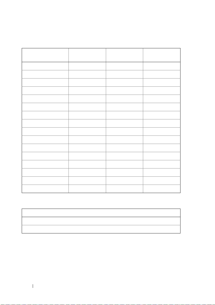
Table B-2. Cluster Node Configuration Information
Node Name Service Tag
Number
Public IP Address Private IP Address
Table B-3. Additional Network Information
Additional Networks
74 Cluster Data Form
Page 75
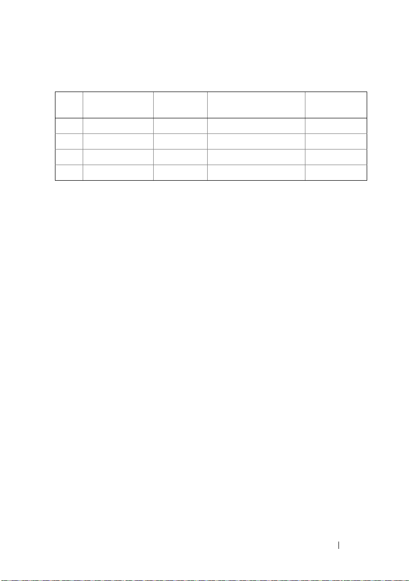
Table B-4. Storage Array Configuration Information
Array Array Service Tag IP Address Number of Attached Disk
Array Enclosures (DAEs)
1
2
3
4
Virtual Disks
Cluster Data Form 75
Page 76

76 Cluster Data Form
Page 77
Zoning Configuration Form
C
Node HBA WWPNs
or Alias
Names
Storage
WWPNs or
Alias Names
Zone Name Zone Set for
Configuration
Name
DELL CONFIDENTIAL – PRELIMINARY 7/25/11 - FOR PROOF ONLY
Template Last Updated - 2/7/2007 Zoning Configuration Form 77
Page 78

FILE LOCATION:
C:\Users\philip_john\Documents\HA_Clusters_Compellent\FalconHead\Sources\appC.fm
DELL CONFIDENTIAL – PRELIMINARY 7/25/11 - FOR PROOF ONLY
78 Zoning Configuration Form
Page 79

Index
A
advanced features
MD3600f and MD3620f storage
systems, 12
virtual disk copy, 12
assigning
drive letters and mount points, 60
C
cabling
mouse, keyboard, and monitor, 19
power supplies, 19
cluster configurations
direct-attached, 12, 24
SAN-attached, 13
cluster data form, 73
cluster storage requirements, 10
configuring
failover cluster, 66
shared storage system, 48
D
Dell PowerVault MD36x0f
storage system
Cabling a Two-Node Cluster, 26
about, 24
E
event log, 56
H
host bus adapter
configuring the Fibre Channel
HBA, 44
I
installing and configuring
storage management software, 47
M
MDSM, 10
Modular Disk Storage
Manager, 10
Modular Disk Storage Manager
Agent, 11
multipath software, MPIO
software, 11
direct-attached cluster
Index 79
Page 80

N
NIC teaming, 24
supported cluster
configurations, 12
O
operating system
installing, 43
P
PowerVault MD36x0f
Cabling a Multi-Node Cluster, 27
PowerVault MD36x0f storage
systems
Cabling Multiple Clusters, 29
Cabling Multiple SAN-Attached
Clusters, 36
Cabling Storage, 30
Zoning, 36
R
recovery guru, 57
S
SAN-Attached Cluster, 13
SAN-attached cluster
about, 30
snapshot virtual disk, 63
T
tape library
connecting to a PowerEdge
cluster, 36
troubleshooting
general cluster, 67
V
virtual disk copy, 65
W
Windows Server 2008,
Enterprise Edition
installing, 43
Z
zones
implementing on a Fibre Channel
switched fabric, 45
zoning configuration form, 77
status icons, 59
storage profile, 57
80 Index
 Loading...