

Page 1

Dell Storage MD1280
Service Guide
Regulatory Model: SP-2584, E11J
Page 2

Notes, cautions, and warnings
NOTE: A NOTE indicates important information that helps you make better use of your computer.
CAUTION: A CAUTION indicates either potential damage to hardware or loss of data and tells you
how to avoid the problem.
WARNING: A WARNING indicates a potential for property damage, personal injury, or death.
Copyright © 2015 Dell Inc. All rights reserved. This product is protected by U.S. and international copyright and
intellectual property laws. Dell™ and the Dell logo are trademarks of Dell Inc. in the United States and/or other
jurisdictions. All other marks and names mentioned herein may be trademarks of their respective companies.
2015 - 03
Rev. A00
Page 3

Contents
1 About the Dell Storage MD1280 Service Guide...............................................5
Dell Storage MD1280 overview.............................................................................................................5
Dell Storage MD1280 hardware......................................................................................................5
Dell Storage MD1280 monitoring................................................................................................... 5
Front-panel features and indicators..................................................................................................... 5
Back-panel features and indicators...................................................................................................... 7
I/O EMM features and indicators.................................................................................................... 8
Fan module features and indicators............................................................................................... 9
PSU features and indicators ......................................................................................................... 10
DDIC indicator..................................................................................................................................... 11
2 Replacing Dell Storage MD1280 components.............................................. 13
Safety precautions............................................................................................................................... 13
Electrical safety precautions..........................................................................................................13
General safety precautions ...........................................................................................................13
Electrostatic discharge precautions .............................................................................................14
Pre-replacement tasks........................................................................................................................ 14
Turning off the EMMs and enclosure............................................................................................14
Replacing PSUs....................................................................................................................................14
Identifying the failed PSU.............................................................................................................. 14
Replacing a PSU.............................................................................................................................14
Replacing fan modules .......................................................................................................................16
Identifying the failed fan module..................................................................................................16
Replacing a fan module.................................................................................................................16
Replacing hard drives.......................................................................................................................... 17
Numbering the hard drive ............................................................................................................ 17
Identifying the failed hard drive.................................................................................................... 18
Replacing hard drives.................................................................................................................... 18
Replacing I/O EMM modules.............................................................................................................. 21
Identifying the failed EMM............................................................................................................ 22
Replacing an EMM.........................................................................................................................22
Replacing chassis................................................................................................................................ 23
Replacing rack rails............................................................................................................................. 23
Post-replacement tasks .....................................................................................................................24
Turning on the EMMs and enclosure........................................................................................... 24
3 Troubleshooting Dell Storage MD1280 components..................................25
Troubleshooting fan modules............................................................................................................ 25
3
Page 4

Troubleshooting PSUs........................................................................................................................ 25
Troubleshooting DDICs...................................................................................................................... 25
Troubleshooting I/O EMMs................................................................................................................ 26
4 Technical specifications....................................................................................27
5 Contacting Dell................................................................................................... 32
4
Page 5

1
About the Dell Storage MD1280 Service Guide
The Dell Storage MD1280 Service Guide provides information about enclosure service and maintenance.
Dell Storage MD1280 overview
A Dell Storage MD1280 enclosure holds the physical disk drive storage. The interface between the
controller I/O cards and the enclosure is referred to as back‐end connectivity.
Dell Storage MD1280 hardware
The Dell Storage MD1280 is a 5U SAS enclosure and supports up to 84 hard drives in 3.5-inch carriers,
installed in a two‐drawer, three‐row, and 14‐column configuration. The Dell Storage MD1280 enclosure
ships with two redundant power supply units (PSUs), five redundant cooling fan modules, and two
redundant 6 Gbps SAS I/O modules.
Dell Storage MD1280 monitoring
The Storage Enclosure Management software enables you to manage, update, and monitor MD1280. For
more information, see Dell Storage MD1280 Administrator's Guide available at www.dell.com/support.
The Dell Storage MD1280 enclosure uses LED indicators to indicate an issue with the enclosure.
NOTE: Dell OpenManage Server Administrator is not available for the Dell Storage MD1280
enclosure.
Front-panel features and indicators
The front panel displays the enclosure and power status.
5
Page 6

Figure 1. Front-panel features and indicators
Table 1. Front-panel features and indicators
Item Name Panel Description
1 Enclosure status indicator
• Unit ID Display: Displays the enclosure
unit identification number. The unit
identification number is helpful when
setting up and maintaining a multiple‐
enclosure configuration.
• Input Switch: Not used.
• Power On/Standby:
– Off — The enclosure power is
turned off
– Green — The enclosure is ‘On’
(operational)
– Amber — The enclosure is in
standby (not operational) mode.
• Module Fault: Amber when there is a
hardware fault. Also, an LED may glow
on a PSU, hard drive, DDIC, fan module,
or EMM indicating a faulty device.
• Logical Status: Amber when there is a
change of status or when devices other
than the enclosure fails.
• Drive drawer 1 Fault: Amber when a
hard drive, cable, or sideplane fails in
drive drawer 1.
6
Page 7

Item Name Panel Description
• Drive drawer 2 Fault: Amber when a
hard drive, cable, or sideplane fails in
drive drawer 2.
2 Drive drawer‐specific left
and right side enclosure
activity indicators
3 Drive drawer‐specific left
and right side status
indicators
Activity Bar Graph: Six variable‐intensity
LEDs glow dynamically displaying access of
the hard drives in that specific enclosure
drive drawer.
• Sideplane OK or Power Good:
– Off — Sideplane card or cable fault
– Green — Sideplane card and cable
are functional (though a fault may
be indicated by one or more of the
following LEDs).
* Drive drawer Fault:
Amber — Sideplane card fault or
hard drive failure causing loss of
availability or redundancy.
* Logical Fault:
• Amber (steady) — Host
indicated hard drive fault
• Amber (blinking) — Arrays in
impacted state
* Cable Fault:
Amber — Cable fault
4 Drive drawer‐specific anti‐
tamper locks
Locks the drive drawer by using a Torx T20
screwdriver until the red arrows point to
the locked icon (away from the center of
the enclosure).
Back-panel features and indicators
The back panel displays PSU, connectivity, and fault indicators.
7
Page 8

Figure 2. Back-panel features and indicators
Table 2. Back-panel features and indicators
Item Control/Feature
1 Optional cable retention positions (4)
2 I/O enclosure management modules (2)
3 Fan modules (5)
NOTE: Each fan module includes two fans. The Storage Enclosure
Management Software lists 10 fans 0–9. The physical enclosure enumerates
the enclosures 1–5. Therefore, in the Storage Enclosure Management
Software, fans 0–1 are related to fan module 0, fans 2–3 are related to fan
module 1, fans 4–5 related to fan module 4, fans 6–7 are related to fan
module 5, and fans 8–9 are related to fan module 5.
4 PSUs (2)
5 Optional cable retention positions (2)
6 Power switches (2)
I/O EMM features and indicators
Dell Storage MD1280 enclosure includes two I/O Enclosure Management Modules (EMMs).
8
Page 9

Figure 3. I/O EMM features and indicators
Table 3. I/O EMM features and indicators
Item Control/Feature Icon Description
1 Fault LED
• Off — Module OK
• Amber — Module fault
2 Power LED
3 Console port Factory use only
4 SAS ports Connect to an HBA or to another
5 SAS port link status
indicator LEDs
• Green (steady) — Module OK
• Green (blinking) — Vital product data
(VPD) fault
• Off — Module fault
enclosure
• Green (steady) — Connected, but not
active
• Green (blinking) — Connected and
active
• Off — Not connected
Fan module features and indicators
Dell Storage MD1280 enclosure includes five fan modules in five interface slots.
9
Page 10
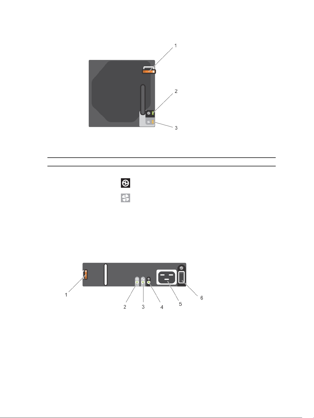
Figure 4. Fan module features and indicators
Table 4. Fan module features and indicators
Item Control/Feature Icon Description
1 Release latch Releases fan from enclosure
2 Module OK Green — Module OK
3 Fan fault Amber — Loss of communication with the fan
module, or reported fan speed is out of
specification.
PSU features and indicators
Dell Storage MD1280 enclosure includes two PSUs in two interface slots.
Figure 5. PSU features and indicators
10
Page 11

Table 5. PSU features and indicators
Item Control/Feature Icon Description
1 Release latch Releases PSU from enclosure
2 PSU fault
3 AC fault
4 Power OK
5 Power Connector Connect the external power supply
6 Power switch The power switch controls the PSU
If all three LEDs are off then there is no AC power supplied to either PSU.
• Amber (steady) — PSU fault or PSU
not working
• Amber (blinking) — PSU firmware is
downloading
• Amber (steady) — AC power is not
detected
• Amber (blinking) — PSU firmware is
downloading
• Green (steady) — PSU is working
• Green (blinking) — AC power is
present, but the PSU is in standby
mode (the other PSU is working)
source to this connector.
output to the system.
DDIC indicator
The Disk Drive In Carrier (DDIC) includes one status indicator.
Figure 6. DDIC indicator
11
Page 12

Table 6. DDIC indicator
Item Feature Icon Indicator Code
1 DDIC fault
indicator
• Amber — Hard drive fault
• Amber (blinking) — When a hard drive or enclosure fails,
or a command is run to blink the drive or the enclosure,
the associated LED blinks every second. When a hard
drive fails, the fault LED of the hard drive drawer that
contains the hard drive blinks. However, when an
enclosure fails, the fault LEDs of all hard drives and both
drive drawers blinks.
12
Page 13

2
Replacing Dell Storage MD1280 components
This section describes the tasks to replace field replaceable units (FRUs) inside the Dell Storage MD1280
enclosure. Here, it is assumed that the user has already received the appropriate replacement device and
is ready to install the device in the enclosure.
Safety precautions
To avoid injury and damage to the enclosure, always follow these safety precautions.
WARNING: See the safety and regulatory information that shipped with your system. Warranty
information may be included within this document or as a separate document.
Electrical safety precautions
To avoid injury and damage to the enclosure, always follow electrical safety precautions.
WARNING: Disconnect power from the enclosure when removing or installing components that
are not hot‐swappable. When disconnecting power, first turn off the EMMs and enclosure.
Remove the power cords from all the PSUs in the enclosure.
• Know the locations of the following in your system environment: power switch of the equipment,
emergency power button, switch to turn off power, and electrical outlet of the system.
• Do not work alone when working with high-voltage components.
• Do not use mats designed to decrease electrostatic discharge as protection from electrical shock.
Instead, use rubber mats that are designed as electrical insulators.
• The PSU cord must include a grounding prong and must be plugged into a grounded electrical outlet.
General safety precautions
To avoid injury and damage to an enclosure, always follow general safety precautions.
WARNING: Do not lift the enclosure without any assistance. If installed above the lower 20U of a
rack, a customer‐provided mechanical lift must be used to avoid injury.
• Keep the area clean and free of clutter around the chassis.
• While working on the enclosure, do not wear loose clothing, such as neckties and unbuttoned shirt
sleeves, which can come into contact with electrical circuits or be pulled into a cooling fan.
• Remove any jewelry or metal objects from your body because they are excellent electricity
conductors that can create short circuits and harm you if they come into contact with printed circuit
boards (PCBs) or areas where power is available.
13
Page 14

CAUTION: If the enclosure system operates for too long (depending on altitude) with drive
drawers open, the enclosure can overheat, causing power failure and data loss. Such use may
invalidate the warranty.
Electrostatic discharge precautions
To avoid injury and damage to the enclosure, always follow electrostatic discharge (ESD) precautions.
ESD is generated by two objects with different electrical charges coming into contact with each other.
The resulting electrical discharge can damage electronic components and PCBs.
• Dell recommends to always use an antistatic mat and antistatic wrist or ankle strap while working on
components in the interior of an enclosure.
• Observe all conventional ESD precautions when handling plug‐in modules and components.
• Avoid contact with backplane components and module connectors.
• When you are not using the components and PCBs, keep them in their antistatic bags.
Pre-replacement tasks
If the FRU is not hot‐swappable, the EMMs and enclosure must be turned off.
Turning off the EMMs and enclosure
About this task
To turn off the EMMs and enclosure, complete the following tasks:
Steps
1. Before turning off the EMMs and enclosure, identify the failed devices.
2. Stop I/O to the storage enclosure.
3. Turn off the EMMs and PSUs in the enclosure using the power switches located on the
corresponding devices.
4. Disconnect power from the enclosure by removing the power cords from all the PSUs in the
enclosure.
Replacing PSUs
The Dell Storage MD1280 enclosure supports two 2.8kW AC hot‐swappable PSUs. If one PSU stops
functioning, the second PSU continues to supply power to the enclosure.
Identifying the failed PSU
To identify a non-functioning PSU, use the secli component of the Storage Enclosure Management
Software or visually verify which PSU is not functioning. For more information on using the secli to
identify failed devices, see the Dell Storage MD1280 Administrator's Guide.
Replacing a PSU
About this task
To replace failed PSUs, complete the following tasks:
14
Page 15

Steps
1. Turn off the PSU switch.
2. Remove the power cord from the securing clip and then remove the power cord from the PSU.
3. Push the red release tab to right and hold it, and then slide the PSU out of the chassis by using the
PSU handle.
CAUTION: The PSUs are heavy. To avoid injury, use both hands while removing the module.
Figure 7. Removing a PSU
1. Release tab 2. PSU
4. Slide the replacement PSU module into the chassis until it is fully seated and the release tab clicks
into place.
5. Connect the power cord to the PSU and ensure that the power cord is inserted into a power outlet.
6. Secure the power cord by using the clip.
15
Page 16

Figure 8. Securing the power cord
1. Power cable securing clip
7. Turn on the PSU switch.
NOTE: Allow the enclosure to identify the PSU and determine its status. If the PSU is functioning
properly, the PSU’s Power OK LED glows green and the PSU fault LED and AC fault LED are off.
Replacing fan modules
The Dell Storage MD1280 enclosure supports five fan modules. If one fan module fails, the remaining
modules continue to cool the enclosure.
NOTE: When a fan module fails, the fan speed in the remaining modules increases significantly to
provide adequate cooling. The fan speed decreases gradually when a new fan module is installed.
Identifying the failed fan module
To identify the failed fan module, use the secli component of the Storage Enclosure Management
Software or visually verify which fan module is not functioning properly. For more information on using
the secli to identify failed devices, see the Dell Storage MD1280 Administrator's Guide.
Replacing a fan module
About this task
To replace a failed fan module, complete the following tasks:
Steps
1. Press the red release tab and pull the fan module out of the chassis by using the handle.
16
Page 17

CAUTION: The fan modules are heavy. To avoid injury, use both hands while removing the
module.
Figure 9. Removing a fan module
1. Fan module 2. Release tab
2. Rotate the replacement fan module so that the release tab and handle are on the right side.
3. Slide the replacement fan module into the chassis until it is fully seated and the release tab clicks into
place.
NOTE: Allow the enclosure to identify the fan module and determine its status. If the fan
module is functioning properly, fan module’s Module OK LED glows green and the battery fault
LED and fan fault LED are off.
Replacing hard drives
The Dell Storage MD1280 enclosure supports hot‐swappable hard drives and supports up to 84 hard
drives in 3.5-inch carriers, installed in a two‐drawer, three‐row, 14‐column configuration. Hard drives are
connected to a backplane by using Disk Drive in Carrier (DDIC) hard drive carriers.
Numbering the hard drive
Hard drives are numbered in the secli, starting with 0. Dell Storage MD1280 DDIC slots are numbered 1–
42 in drive drawer 0, from front to back and left to right, and 43–84 in drive drawer 1.
NOTE: The enumeration of hard drives in the secli software is zero-based. The physical enclosure
enumerates hard drives starting from 1.
17
Page 18

Figure 10. Numbering the hard drive
1. Drive drawer 1 2. Drive drawer 0
Identifying the failed hard drive
To identify the failed hard drive, use the secli component of the Storage Enclosure Management Software
or visually verify the failed hard drive. For more information on using the secli to identify failed devices,
see the Dell Storage MD1280 Administrator's Guide.
Replacing hard drives
About this task
Hard drives can be replaced one at a time without turning off the enclosure. To replace failed hard drives,
complete the following tasks:
Steps
1. Find the Dell Storage MD1280 enclosure and the drive drawer containing the failed hard drive. The
fault drive drawer LED glows.
18
Page 19

Figure 11. Opening a DDIC
1. Drive drawer latches (2 per drawer) 2. Drive drawer
CAUTION: Before opening a drive drawer, ensure that the system is not indicating a
temperature warning. This issue must be rectified first to avoid potential hard drive failure
and data loss.
2. Push and hold both red drive drawer latches toward the center of the drive drawer and pull the drive
drawer out.
CAUTION: If the Dell Storage MD1280 enclosure operates for too long (depending on
altitude) with drive drawers open, the enclosure can overheat, causing potential hard drive
failure and data loss. Such use may invalidate the warranty.
3. Find the failed DDIC by the glowing LED.
4. Press the release button to unlatch the DDIC.
5. Wait for 10 seconds for the hard drive to spin down.
6. Slide the DDIC up and out until it is free of the DDIC slot.
19
Page 20

Figure 12. Removing a DDIC
1. Hard drive fault LED 2. Release button
3. DDIC
NOTE: Leave the hard drive in the carrier. The replacement hard drive will be in the carrier and
attempting to remove the carrier can cause the carrier to break.
7. Slide the replacement DDIC into the slot, push and hold the DDIC down while sliding it toward the
back of the enclosure until the DDIC latches to the backplane.
CAUTION: If the DDIC fails to latch, do not use it and request a replacement. If a faulty DDIC
unlatches within a closed drive drawer then you will not be able to open the drive drawer.
CAUTION: To maintain proper airflow, the drive drawers must be populated with hard drives
in whole rows at a time (there are three rows of 14 hard drives per drawer). The minimum
number of hard drives in an enclosure is 14 (one full, front row in the top drive drawer), the
number of populated rows between drive drawers must not differ by more than one. The
rows should be populated from the front to the rear of the enclosure.
20
Page 21

Figure 13. Closing a drive drawer
1. Drive drawer 2. Open-drawer lock
8. Close the drive drawer.
a. Pull and hold both drive drawer releases and push the drive drawer inside slightly.
b. Release and push the drive drawer until it clicks into a place.
WARNING: After releasing the open‐drawer locks, move hands away from the slides to avoid
injury while pushing the drive drawer inside.
NOTE: Allow the enclosure to identify the hard drive and determine its status. If the hard drive is
functioning properly, DDIC LED is off.
Replacing I/O EMM modules
The Dell Storage MD1280 enclosure supports redundant hot‐swappable I/O Enclosure Management
Modules (EMMs).
EMMs provide the following data path and enclosure management functions for the enclosure:
• Monitoring and controlling enclosure environment elements such as temperature, fan, PSUs, and
enclosure LEDs
• Controlling access to hard drives
• Communicating enclosure attributes and states to the host
21
Page 22

Identifying the failed EMM
To identify the failed EMM, use the secli component of the Storage Enclosure Management Software or
visually verify the EMM that is not functioning. For more information on using the secli to identify failed
devices, see the Dell Storage MD1280 Administrator's Guide.
Replacing an EMM
About this task
EMMs can be replaced one at a time without turning off the enclosure. To replace failed EMMs, complete
the following tasks:
Steps
1. Remove all cables from the EMM. Ensure all the cables are labeled.
2. Push the release tab to right and pull the release lever away from the chassis.
3. Grasp the release lever and pull the EMM away from the chassis.
Figure 14. Replacing an EMM
1. EMM 2. EMM release lever
4. Insert the replacement EMM into the bay until it is fully seated.
5. Push the release lever toward the chassis until it clicks into place.
6. Connect all the cables to the EMM.
22
Page 23

Replacing chassis
Replacing the chassis is required when non-FRU devices must be replaced. Replacing a chassis requires a
scheduled maintenance window when the system is unavailable. The replacement chassis comes without
any FRUs, and therefore all cards and DDICs must be transferred to the new chassis.
About this task
To replace a chassis, complete the following tasks:
Steps
1. Remove the Hold Down Brackets (HDBs).
a. Remove the fixing screws from the rear of the enclosure.
b. Remove the HDBs from the rear of the rack.
2. Remove all DDICs from the enclosure and place on a static free mat or bench. Note the slot position
of each DDIC as you remove it, the DDICs must be reinstalled in the same slot position as in the
original chassis.
3. Remove the enclosure from the rack rails.
WARNING: Do not attempt to lift the enclosure without any assistance. If installed above the
lower 20U of a rack, a customer‐provided mechanical lift must be used to avoid injury.
4. Install the replacement chassis in the rack.
5. Install the HDBs.
6. Move all the back‐panel parts (EMMs, fans, and PSUs) from the original chassis to the racked
replacement.
7. Move the front panel bezel from drive drawer 0 from the original chassis onto the racked
replacement.
8. Install the DDICs into the replacement.
9. Turn on the enclosure as described in the Post-replacement tasks section in this document.
10. An update to the electronically stored product ID and Service Tag must be applied. Contact your
service provider.
11. Swap the bezel on drive drawer 0 of the failed chassis with the bezel on drive drawer 0 of the new
chassis before loading back into the rack.
12. Service Tag is not included in the replacement chassis. Remove the Service Tag label from the old
chassis and adhere it to the replacement chassis. Alternatively, mark the replacement chassis with the
Service Tag information or print a new tag.
Replacing rack rails
Rack rails are used to install the Dell Storage MD1280 enclosure into a rack.
About this task
To replace rack rails, complete the following tasks:
NOTE: This procedure contains high‐level tasks. For more information about the instructions, see
Rack Installation Instructions document available at www.dell.com/support.
the
Steps
1. Turn off the EMMs and enclosure as described in the Pre-replacement tasks section in this
document.
2. Remove the HDBs.
a. Remove the fixing screws from the rear of the enclosure.
23
Page 24

b. Remove the HDBs from the rear of the rack.
3. Remove the enclosure from the rack rails.
WARNING: Do not attempt to lift the enclosure without any assistance. If installed above the
lower 20U of a rack, a customer‐provided mechanical lift must be used to avoid injury.
4. Remove the rack rails from the rack.
5. Install the replacement rack rails in the rack.
6. Install the enclosure in the rack rails.
7. Install the HDBs.
8. Turn on the EMMs and enclosure as described in the Post-replacement tasks section in this
document.
Post-replacement tasks
After replacing an FRU in Dell Storage MD1280, turn on the EMMs and enclosure, if they were turned off.
Turning on the EMMs and enclosure
About this task
If the servers and enclosure are turned off, turn on the servers by doing the following:
Steps
1. Insert the power cords.
2. Press the power button on the enclosures to turn on the power.
NOTE: Always turn on the enclosures before turning on the host.
3. Ensure that the host is turned on.
4. Use the secli component of the Storage Enclosure Management Software to verify the replacement
device is up and running. For more information on using the secli to identify failed devices, see the
Dell Storage MD1280 Administrator's Guide
5. Install all available firmware update by using secli. For more information on using the secli to update
firmware, see the Dell Storage MD1280 Administrator's Guide.
24
Page 25

Troubleshooting Dell Storage MD1280 components
This section contains basic troubleshooting tasks for components inside the Dell Storage MD1280
enclosure.
Troubleshooting fan modules
About this task
To troubleshoot fan modules, complete the following tasks:
Steps
1. Determine the status of the fan module LEDs.
If the fan fault LED glows, it implies that the fan module has failed.
2. Reseat the fan module by removing and reinstalling it.
NOTE: Allow the enclosure to identify the fan module and determine fan’s status.
Troubleshooting PSUs
3
About this task
To troubleshoot PSUs, complete the following tasks:
Steps
1. Determine the status of the PSU LEDs.
a. If the PSU fault LED glows, it implies that the PSU has failed.
b. If the Power OK LED is not glowing, check the power cord and power source into which the PSU
is inserted:
1. Connect another device to the power source and check whether the device works.
2. Insert power cord to a different power source.
3. Replace the power cord.
c. If the AC fault LED glows, this PSU is not supplying power, though the other PSU may still be
supplying the power.
2. Reseat the PSU by removing and reinstalling it.
NOTE: Allow the enclosure to identify the PSU and determine PSU’s status.
Troubleshooting DDICs
About this task
To troubleshoot DDICs, complete the following tasks:
25
Page 26

Steps
1. Determine the status of DDIC LED.
a. If the DDIC fault LED glows, it implies that the hard drive has failed.
CAUTION: Confirmed that the particular hard drive contains no user data. The Fault LED
alone is not an indication the hard drive can be safely removed.
b. If the DDIC fault LED is not glowing, perform task 2 here.
2. Check the connectors and reseat the DDIC.
CAUTION: This task should be only performed on unmanaged hard drives or after it is
confirmed that the particular hard drive contains no user data. Mere glowing of Fault LED
does not imply that the hard drive has failed (you can remove the hard drive even if the Fault
LED is glowing).
a. Remove the DDIC.
b. Check the DDIC and the backplane to ensure that the connectors are not damaged.
c. Reinstall the DDIC. Ensure the DDIC contacts the backplane.
Troubleshooting I/O EMMs
About this task
To troubleshoot I/O EMMs, complete the following tasks:
Steps
1. Check the pins and reseat the EMM.
a. Remove the EMM.
b. Verify that the pins on the backplane and the EMM are not bent. If any pins are bent, do not
attempt to correct them; instead, contact Dell technical support services for further instructions.
c. Reinstall the EMM.
2. Determine the status of the EMM power and Fault LEDs. If the Fault LED glows, it implies that the
EMM has failed.
3. Verify link status. If the link status LEDs are not glowing green, check the cables.
a. Reseat the cables on the enclosure and the controller.
b. Recheck the link status LEDs. If the link status LEDs are not glowing green, replace the cables.
4. Reseat the EMM by removing and reinstalling it.
26
NOTE: Allow the enclosure to identify the EMM and determine its status.
Page 27

4
Technical specifications
The technical specifications of the MD1280 are displayed in the following tables.
Drives
SAS hard drives Up to 84 SAS hot-swappable hard drives (6.0 Gbps
or 12.0 Gbps) and SSDs
Enclosure Management Modules (EMM)
EMMs Two hot-swappable I/O EMM modules
Connectivity
Configurations Various server-attached configurations as specified
by your solution provider.
Backpanel Connectors
SAS connectors
• Asymmetric SAS Cabling for connection to the
host and for expansion to an additional
enclosure
• Support Mini-SAS to Mini-SAS cable universally
keyed for the following lengths that are
currently supported: 0.5m–6m
NOTE: SAS connectors are SFF-8086/
SFF-8088-compliant.
LED Indicators
Front panel
Disk Drive In Carrier (DDIC) One single-color LED for hard drive fault status
• One two-digit LCD indicator for Unit ID, error
code, and unit location identifier
• One two-color LED indicator for power status
• One single-color LED indicator for module fault
status (enclosure as a whole)
• One single-color LED indicator for logical fault
status (hard drive, HBA, RAID controller)
• One single-color LED indicator for drive drawer
1 fault status
• One single-color LED indicator for drive drawer
2 fault status
27
Page 28

LED Indicators
6 Gbps SAS I/O module 14 one-color LED status indicators, four each for
the three SAS ports, and two for the module status
Fan module
PSU
Power Supply Units (per PSU)
Watt 2.8 kW
Voltage 200–240 VAC (8.6 A–4.3 A)
Heat dissipation 191–147 W
Maximum inrush current Under typical line conditions and over the entire
• One single-color LED indicator for module
status
• One single-color LED indicator for battery fault
status (not currently used)
• One single-color LED indicator for fan fault
status
• One single-color LED indicator for power
status
• One single‐color LED indicator for PSU fault
status
• One single‐color LED indicator for AC fault
status
• One single‐color LED indicator for power status
system ambient operating range, the inrush current
may reach 55 A for each PSU for 10 ms or less.
Available Hard Drive Power (Per Slot)
Supported hard drive power consumption
(continuous)
I/O Card Power (Per Slot)
Maximum power consumed by I/O Card 11 W at +12 V
Maximum available power 100 W at +12 V
Maximum available power 1 W at +5 V (standby)
Physical
Height 22.23 cm (8.75 inches)
Width 48.26 cm (19 inches)
28
Up to 1.16 A at +5 V, Up to 1.6 A at +12 V
Page 29

Physical
Depth (front mounting bracket to rear surface) 91.5 cm (36 inches)
Depth (front surface to rear surface) 96 cm (38 inches)
Full Weight (maximum configuration) 130.7 kg (287.5 lb)
Shipping Weight (without hard drives) 62 kg (137 lb)
29
Page 30

Environmental
NOTE: For more information about environmental measurements for specific system
configurations, see dell.com/environmental_datasheets.
Temperature
Operating 5° to 35°C (41° to 95°F) with a maximum
temperature gradation of 10°C per hour
NOTE: Maximum 35°C up to 2134 m (7000 ft),
derate to 30°C for 2134 m to 3000 m (7000 ft
to 10,000 ft).
Storage –40° to 70°C (–40° to 158°F) with a maximum
temperature gradation of 20°C an hour
Relative humidity
Operating 20 percent to 80 percent (noncondensing) with a
maximum humidity gradation of 10 percent an
hour
Storage 5 percent to 100 percent (noncondensing)
Maximum vibration
Operating 0.21 g at 5–500 Hz for 15 min
Storage 1.04 g at 2–200 Hz for 15 min
Maximum shock
Operating Half-sine shock 5 g +/- 5 percent with a pulse
duration of 10 ms +/- 10 percent in operational
orientations only
Storage
Altitude
Operating –30.5 to 3000 m (–100 to 10,000 ft)
Storage –300 m to 12,192 m (–1000 ft to 40,000 ft)
Airborne Contaminant Level
Class G2 or lower as defined by ISA-S71.04-1985
• z-axis: 30 g 10 ms half-sine
• x-axis and y-axis: 20 g 10 ms half-sine
NOTE: Maximum 35°C up to 2134 m (7000 ft),
derate to 30°C for 2134 m to 3000 m (7000 ft
to 10,000 ft).
30
Page 31

31
Page 32

5
Contacting Dell
Dell provides several online and telephone-based support and service options. If you do not have an
active Internet connection, you can find contact information on your purchase invoice, packing slip, bill,
or Dell product catalog. Availability varies by country and product, and some services may not be
available in your area. To contact Dell for sales, technical support, or customer-service issues:
1. Go to dell.com/support.
2. Select your country from the drop-down menu on the bottom right corner of the page.
3. For customized support:
a. Enter your system Service Tag in the Enter your Service Tag field.
b. Click Submit.
The support page that lists the various support categories is displayed.
4. For general support:
a. Select your product category.
b. Select your product segment.
c. Select your product.
The support page that lists the various support categories is displayed.
32
 Loading...