

Page 1

Welcome - Getting Started
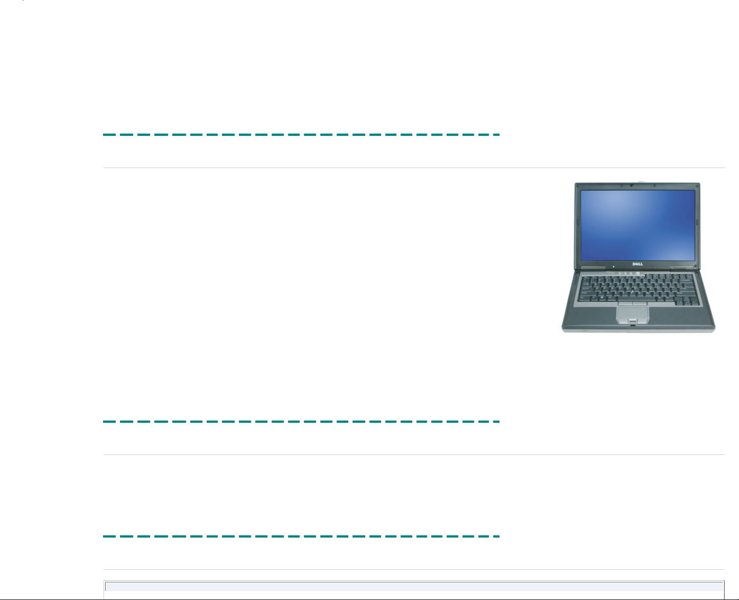
This document contains information about the Latitude™ D620.
The Latitude D620 training course goal is to prepare you to accurately and effectively resolve customer inquiries and technical issues and to inform you of the proper steps for replacing hardware. This course also gives an overview
of the system BIOS, features, keyboard shortcuts, and safety precautions.
RTS Dates: Americas - 04/07/2006
Europe - 04/07/2006
Brazil - 04/07/2006
Asia Pacific - 04/07/2006
Japan - 04/07/2006
China - 04/07/2006
Departments:
Global Technical Curriculum Development (GTCD)
Contributing Sources:
Contacting Dell:
To contact Dell regarding issues with this training material, click the following link: Feedback.
Information in this document is subject to change without notice.
© 2006 Dell Inc. All rights reserved. Rev. A06
Reproduction in any manner whatsoever without the written permission of Dell Computer Corporation is strictly forbidden.
Trademarks used in this text: Dell, the DELL logo, and Dimension are trademarks of Dell Computer Corporation; Intel, Pentium, and Celeron are registered trademarks of Intel Corporation; Microsoft and Windows are registered
trademarks of Microsoft Corporation.
Other trademarks and trade names may be used in this document to refer to either the entities claiming the marks and names or their products. Dell Computer Corporation disclaims any proprietary interest in trademarks and trade
names other than its own.
Printed 2/22/2007 5:44:33 PM Latitude™ D620 For Dell Employees Only
Expires 2/23/2007 5:44:33 PM Welcome - Getting Started This document is Dell Confidential
Using this Material
The following sections provide information to help you effectively use this training material.
Navigating the Material
To navigate through this course, select topics using either the left navigation menu or the Previous/Next buttons at the top right corner of each page.
This course is designed to be completed in the order in which the topics are presented. However, refresher training can be accomplished in any desired order.
Important Symbols
The following symbols are used to emphasize important notations in this material:
A NOTE indicates important information that helps you make better use of your computer.
A WARNING indicates either potential damage to hardware or loss of data and tells you how to avoid the problem.
A CAUTION indicates a potential for property damage, personal injury, or death.
Page 2
Browser Requirements
Dell's online courses are designed to work with Internet Explorer® 5.x and later, Netscape® versions 6.x and later, and Mozilla® 1.0.1. If you experience problems with the courseware related to your browser, please contact us:
us_dcse@dell.com
Additional Required Software
Adobe® Acrobat® (.pdf) files require Acrobat Reader®. You can download Acrobat Reader and get additional information from Adobe's website: http://www.adobe.com/products/acrobat/.
Printed 2/22/2007 5:44:33 PM Latitude™ D620 For Dell Employees Only
Expires 2/23/2007 5:44:33 PM Using this Material This document is Dell Confidential
Marketing Information
The Latitude™ D620 is positioned as Latitude's mainstream thin and light D-Family product, designed for workers who frequently travel and value mainstream
performance with full-size 14.1" displays and integrated optical drives. It targets large corporate accounts with a strong focus on manageability, cost of ownership,
security, and integrated communications delivered in a notebook with a high level of quality, fit, and finish.
The D620 replaces the D610 as Latitude's mainstream thin and light corporate notebook. It is a 2-spindle design optimized around a wide-aspect 14.1" display. The
D620 delivers mainstream performance with the Intel® Napa architecture, the new Latitude Laminar design language, and integrated wireless communications
(including support for integrated configurable cellular WAN), all at a lower weight than the D610 with an optimized profile height associated with the wide-aspect display.
Cost for the D620 is managed with the goal of cost-point replacement to the D610.
The Latitude brand promise is maintained by offering managed transitions, system manageability, and essential commonality with the Latitude D-Family. The D620 is
compatible with the D-Family docking, AC adapters, and D-Family media modules and peripherals. This system supports key D-Family features such as smart card
technology, TPM, gigabit Ethernet, mini card slots, and dual-pointing devices.
These are some of the goals considered in the Latitude D620's development:
● Delivery of Intel's Napa architecture (features/performance)
● D-Family commonality
● Size and weight
● Battery life
● Cost
● RoHS compliance
Printed 2/22/2007 5:44:33 PM Latitude™ D620 For Dell Employees Only
Expires 2/23/2007 5:44:33 PM Marketing Information This document is Dell Confidential
RoHS Overview
The Latitude™ D620 is fully RoHS compliant.
Printed 2/22/2007 5:44:33 PM Latitude™ D620 For Dell Employees Only
Expires 2/23/2007 5:44:33 PM RoHS Overview This document is Dell Confidential
Product Overview
Latitude™ D620 RTS Dates
Page 3
Americas Europe APCC Japan CCC Brazil
04/07/06 04/07/06 04/07/06 04/07/06 04/07/06 04/07/06
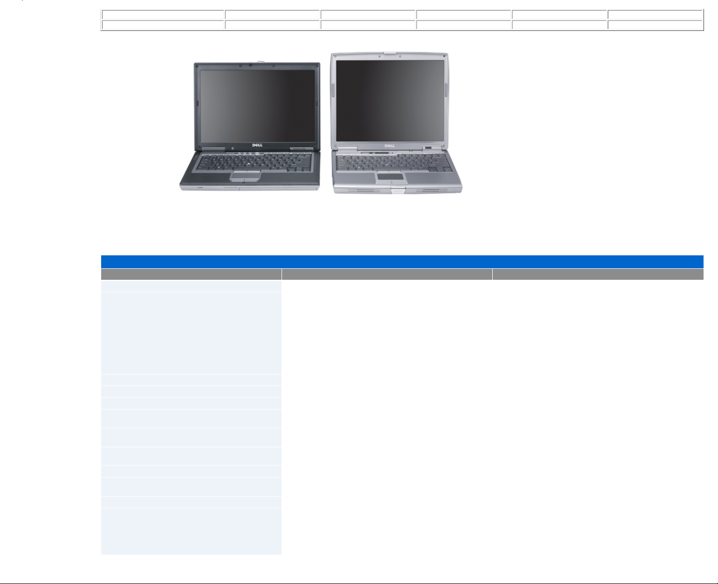
Latitude D620 Latitude D610
The table below compares the Latitude D620 to the older D610.
Product Overview
Features Latitude D620 Latitude D610
Processor type
Intel® Core™ 2 Duo, Core Duo, and Core Solo (Merom and Yonah) Intel Pentium® M (Dothan)
Processor speeds
Core 2 Duo:
2.0 GHz
2.16 GHz
2.33 GHz
Dual core:
1.67 GHz
1.83 GHz
2.0 GHz
2.17 GHz
Single core
1.67 GHz
Single core:
1.6 GHZ (730)
1.8 GHz (740)
1.9 GHz (750)
2.0 GHz (760)
2.1 GHz (770)
System chipset
Calistoga 945GM / 945PM Alviso 915GM / 915PM
Memory
DDR2 533/667 MHz SODIMM modules DDR2 400/533 MHz SODIMM modules
Memory min/max
256 MB / 4096 MB 256 MB / 2048 MB
LCD types
14.1" WXGA (1280x800)
14.1" WXGA+ UltraSharp™ (1440x900)
14" XGA (1024x768)
14" SXGA+ (1400x1050)
Video
NVIDIA® Quadro® NVS 110M 64-bit
Intel 950GMA
ATI™ M22CSP64 Mobile
Intel UMA internal
Video memory
64 MB dedicated / 128 MB shared
Up to 224 MB shared
128 MB
Audio
SigmaTel® STAC9200 (Azalia codec) SigmaTel STAC9751
USB support
Two back ports
Two side ports
Two back ports
Two side ports
Hard drive interface
SATA IDE
Media bay options
Floppy disk drive (optional)
24x CD-ROM drive
24x CDRW/DVD drive
8x DVD+/–RW drive
Second 40 GB hard drive
Second battery
Page 4

Wireless options
WLAN:
Dell™ Wireless 1390 Mini Card
Dell Wireless 1390 ExpressCard™ (post RTS)
Dell Wireless 1490 Mini Card
Intel PRO/Wireless 3945 Mini Card
WWAN:
Dell Wireless 5500 Mobile Broadband Mini Card
Dell Wireless 5700 Mobile Broadband Mini Card
Dell Wireless 5505 Mobile Broadband Mini Card (Europe only)
Intel 2915 Mini PCI®
Dell Wireless 1350 Mini PCI
Dell Wireless 1450 Mini PCI
Intel PRO/Wireless 2200 Mini PCI
Intel PRO/Wireless 2100 Mini PCI
Bluetooth® support
Dell 350 Bluetooth v2.0 + Enhanced Data Rate (EDR) Dell 350 Bluetooth Internal Wireless Card
NIC (LOM)
Broadcom® BCM5752 Integrated Gigabit Ethernet Broadcom BCM5751 Integrated Gigabit Ethernet
Modem
Conexant® HDA D110 MDC w/ Azalia codec Conexant MDC Internal Modem, 56K, V.90
I/O card slots
O
2
Micro® Oz601 Controller
PC Card™ Slot
Smart card slot
Texas Instruments™ PCI6515 CardBus/smart card controller
IR support
IRDA 1.1
IR at 4 Mbit/s using the SMsC Macallan III I/O controller and a Vishay
TDFU6102F IrDA transceiver
Ports and connectors
Power
VGA (video)
Serial
RJ-45 (network)
RJ-11 (modem)
USB 2.0 (four)
IrDA
Audio (headphone and mic)
D-Port connector
Power
VGA (video)
S-video
Serial
Parallel
RJ-45 (network)
RJ-11 (modem)
USB 2.0 (four)
IrDA
Audio (headphone and mic)
D-Port connector
Operating system
Windows® XP Home SP2
Windows XP Pro SP1
Windows XP Pro SP2
Windows Pro 64-bit
Windows Vista™ (when available)
Novell® Certification
n Series
Windows XP Home
Windows XP Professional
Docking support
D-Dock expansion station
D-Port APR
AC adapter
65 W
(90 W with D-Series dock)
Battery
Lithium Ion 9-cell 85 WHr
Lithium Ion 6-cell 56 WHr
Lithium Ion 4-cell 35 WHr
Lithium Ion 6-cell 53 WHr
Lithium Ion 6-cell 48 WHr
Lithium Ion 4-cell 32 WHr
Weight
~5 pounds ~5 pounds
Printed 2/22/2007 5:44:33 PM Latitude™ D620 For Dell Employees Only
Expires 2/23/2007 5:44:33 PM Product Overview This document is Dell Confidential
System Specifications
Page 5

● Processors
● PC Card™
● Memory
● Communications
● Audio
● Keyboard
● Fingerprint Reader
● Battery
● Physical
● System Information
● Smart Card
● Ports and Connectors
● Graphics
● Display
● Touch Pad
● Track Stick
● AC Adapter
● Environmental
Processors
Processor type
Intel® Core™ Solo and Intel Core Duo processors
Level 1 (L1) cache
64 KB (Internal)
Level 2 (L2) cache
2 MB (on-die)
External bus frequency
667 MHz
System Information
System chipset
Intel 945GM or 945 OM
Data bus width
64 bits
DRAM bus width
64 bits
Processor address bus width
36 Bits
PC Card
Cardbus controller
O
2
Micro® Oz601 CardBus Controller
PC Card connector
One (supports one Type I or Type II card)
Cards supported
PC Card: 3.3 V and 5 V
ExpressCard™: 34 mm with adapter
PC Card connector size
80 Pins
Data width (maximum)
PCMCIA: 16 Bits
CardBus: 32 Bits
Smart Card
Read/write capabilities
Reads and writes to all ISO 7816 1/2/3/4 microprocessor cards (T=0, T=1)
Cards supported
3 V and 5 V
Program technology supported
Java Cards™
Interface speed
9600–115,200 BPS
EMV level
Level 1 certified
WHQL certification
PC/SC
Compatibility
Compatible within a PKI environment
Insert/eject cycles
Certified for up to 100,000 cycles
Page 6

Memory
Memory module connectors
Two user-accessible SODIMM sockets
Memory module capacities
256, 512, 1024, 2048 MB
Memory type
533 and 667 MHz DDR2 SDRAM
Minimum memory
256 MB (for some regions, the amount of memory may differ)
Maximum memory
4 GB
Ports and Connectors
Serial
9-pin connector; 16550C-compatible, 16-Byte buffer connector
Video
15-hole standard VGA connector
Audio
Microphone mini-connector, stereo headphones/speakers mini-connector
USB
Four 4-pin USB 2.0-compliant connectors
Infrared
Sensor compatible with IrDA Standard 1.1 (Fast IR) and IrDA Standard 1.0 (Slow IR)
Modem
RJ-11 support
Network adapter
RJ-45 port
D-Dock
Standard D-dock connector for devices such as D-Docks, advanced port replicators, and expansion stations
Communications
Modem
Type v.92 56K MDC
Controller Soft modem
Interface Intel High Definition Audio (HDA) Bus
Network adapter
1 Gb Ethernet LAN on system board
Wireless
WLAN card, wireless switch with Dell™ Wi-Fi® catcher technology, internal card with Bluetooth® wireless technology, and
Dell Mobile Broadband card
(The availability of the Dell Mobile Broadband card may vary by region.)
Graphics
Video type
Integrated on system board, hardware accelerated
Data bus
Integrated video
Video controller
Intel Extreme Graphics
Video memory
Integrated video 256 MB or 512 MB of shared system memory
(Up to 224 MB shared if total computer memory is 512 MB or greater; up to 128 MB shared if total computer memory is 256
MB.)
LCD interface
LVDS
TV output
NTSC or PAL in S-video and composite modes
Color support
16.7 million
Video type
Discrete video adapter, 128-bit hardware accelerated
Data bus
PCI-E x16
Video controller
NVIDIA® Quadro® NVS 110M with TurboCache™
Video memory
Up to 256 MB
(Total of local and shared system memory used may be up to 256 MB for graphics, dependent on system memory size and
other factors. Local integrated memory is 64 MB. Up to 192 MB of system memory may be allocated to support graphics on
computers with 512 MB or more of system memory for a total of 256 MB graphics memory; up to 64 MB of system memory
may be allocated to support graphics on computers with 256 MB system memory for a total of 128 MB graphics memory.)
LCD interface
LVDS
TV output
NTSC or PAL in S-video and composite modes
Color support
16.7 million
Page 7

Audio
Audio type
High Definition Audio (Soft Audio)
Audio controller
SigmaTel® STAC9200
Stereo conversion
24-Bit (stereo digital-to-analog)
24-Bit (stereo analog-to-digital)
Interfaces
Internal PCI Bus/High Definition Audio
External Microphone mini-connector, stereo headphones/speakers mini-connector
Speakers
One 4-ohm speaker
Internal speaker amplifier
2 W channel into 4 Ohms
Volume controls
Keyboard shortcuts or program menus
Display
Type (active-matrix TFT)
WXGA or WXGA+
Active area (X/Y)
303.36 x 189.5
Dimensions
Height 214.3 mm (8.4 inches)
Width 285.7 mm (11.3 inches)
Diagonal 357.1 mm (14.1 inches)
Operating angle
0° (closed) to 180°
Viewing angles
WXGA horizontal 40/40°
WXGA vertical 10/30°
WXGA+ horizontal 65/65°
WXGA+ vertical 50/50°
Pixel pitch
WXGA 0.2588
WXGA+ 0.1971
Power consumption
(panel with backlight, typical)
WXGA 5.0 W (max)
WXGA+ 5.5 W (max)
Controls
Brightness can be controlled through keyboard shortcuts
Keyboard
Number of keys
87 (U.S. and Canada); 88 (Europe); 91 (Japan)
Key travel
Approx. 2.5 mm (0.098 inch)
Key spacing
19.05 mm ± 0.3 mm (0.75 inch ± 0.012 inch)
Layout
QWERTY/AZERTY/Kanji
Touchpad
X/Y position resolution
(graphics table mode)
240 CPI
Active area
73.7 x 43
Size
Page 8

Width 64.88 mm (2.55 inch) sensor-active area
Height 48.88 mm (1.92 inch) rectangle
Fingerprint Reader (Optional)
Type
UPEK TCS3 TouchStrip™ strip sensor with CMOS active capacitive pixel-sensing technology
Power supply
2.7 V to approx. 3.6 V
Connector
48-ball BGA
Array size
248 x 2 pixels
Track Stick
X/Y position resolution
(graphics table mode)
250 count/sec @ 100 GF
Size
Protrudes 0.5 mm higher than surrounding keycaps
Battery
Type
9-cell Lithium Ion battery
85 WHr
(You cannot use an auto/air adapter with a 9-cell battery.)
6-cell Lithium Ion battery 56 WHr
4-cell Lithium Ion battery 35 WHr
Dimensions
Depth
4- or 6-cell Lithium Ion battery 66.6 mm (2.62 inches)
9-cell Lithium Ion battery 93.3 mm (3.67 inches)
Height
4- or 6-cell Lithium Ion battery 19.2 mm (0.76 inch)
9-cell Lithium Ion battery 20.59 mm (0.81 inch)
Width
4- or 6-cell Lithium Ion battery 185.22 mm (72.92 inches)
9-cell Lithium Ion battery 287.30 mm (11.31 inches)
Weight
4-cell Lithium Ion battery 0.24 kg (0.53 lb)
6-cell Lithium Ion battery 0.33 kg (0.73 lb)
9-cell Lithium Ion battery 0.51 kg (1.12 lb)
Voltage
14.8 VDC
Charge time (approximate)
Approximately 1 hour to reach 80% charge
(You must use a 90 W AC adapter to use ExpressCharge with a 9-cell battery.)
Operating time
Varies depending on operating conditions and can be significantly reduced under certain power-intensive conditions
Life span (approximate)
500 discharge/charge cycles
Temperature range
Operating 0° to 35° C (32° to 95° F)
Storage –40° to 65° C (–40° to 149° F)
AC Adapter
Types
65 W and 90 W
Page 9

Input voltage
90–264 VAC
Input current (max)
1.7 A
Input frequency
47–63 Hz
Output current
65 W 4.34 A (maximum at 4-second pulse); 3.34 A (continuous)
90 W 5.62 A (maximum at 4-second pulse); 4.62 A (continuous)
Output power
65 W or 90 W
Rated output voltage
19.5 VDC
Dimensions
65 W
Height 27.8–28.6 mm (1.10–1.12 inches)
Width 57.9 mm (2.28 inches)
Length 137.2 mm (5.40 inches)
90 W
Height 33.8–34.6 mm (1.34–1.36 inches)
Width 60.9 mm (2.39 inches)
Length 153.42 mm (6.04 inches)
Weight (without cables)
65 W: 0.36 kg (0.79 lb)
90 W: 0.46 kg (1.01 lb)
Temperature range
Operating 0° to 35° C (32° to 95° F)
Storage –40° to 65° C (–40° to 149° F)
Physical
Height
32 mm (1.26 inches)
Width
337 mm (13.3 inches)
Depth
238 mm (9.3 inches)
Weight
With travel module and 4-cell battery 1.98 kg (4.37 lb)
With CD-ROM drive and 6-cell battery 2.27 kg (5.0 lb)
Environmental
Temperature range
Operating 0° to 35° C (32° to 95° F)
Storage –40° to 65° C (–40° to 149° F)
Relative humidity
Operating 10% to 90% (noncondensing)
Storage 5% to 95% (Noncondensing)
Maximum vibration (using a random-vibration
spectrum that simulates user environment)
Operating 0.66 GRMS
Storage 1.30 GRMS
Maximum shock (measured with hard drive in
head-parked position and a 2-ms half-sine pulse):
Operating 122 G
Storage 163 G
Altitude
Operating –15.2 to 3048 m (–50 to 10,000 ft)
Storage –15.2 to 10,668 m (–50 to 35,000 ft)
Page 10
Printed 2/22/2007 5:44:33 PM Latitude™ D620 For Dell Employees Only
Expires 2/23/2007 5:44:33 PM System Specifications This document is Dell Confidential
Chassis Overview
Three different batteries are available for the Latitude™ D620 system. The chassis appearance changes when the 9-cell battery is installed. The 9-cell battery includes a palm
rest of sorts that protrudes from the front of the system. The top of the battery palm rest is level with the system palm rest. It does not detach from the battery since it is part of the
battery.
The chassis section is broken down into two groups of pictures: One group contains photos of the system with the 6-cell or 4-cell battery installed, and the second contains
pictures of the system with the 9-cell battery installed. Click all photos in both sections to view larger images in a new browser window.
Printed 2/22/2007 5:44:33 PM Latitude™ D620 For Dell Employees Only
Expires 2/23/2007 5:44:33 PM Chassis Overview This document is Dell Confidential
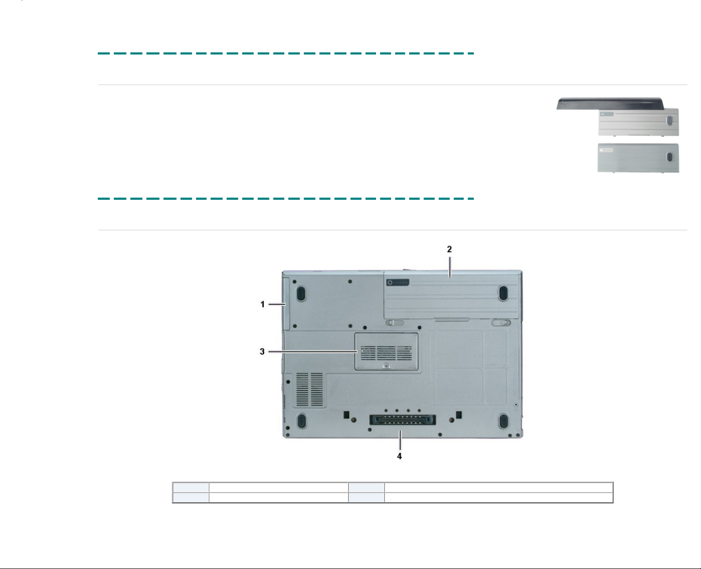
Chassis Bottom
Click the picture above to see a larger image in a new window.
1
Hard drive
3
Memory door
2
Battery
4
D-Dock connector
Printed 2/22/2007 5:44:33 PM Latitude™ D620 For Dell Employees Only
Expires 2/23/2007 5:44:33 PM Chassis Bottom This document is Dell Confidential
Page 11
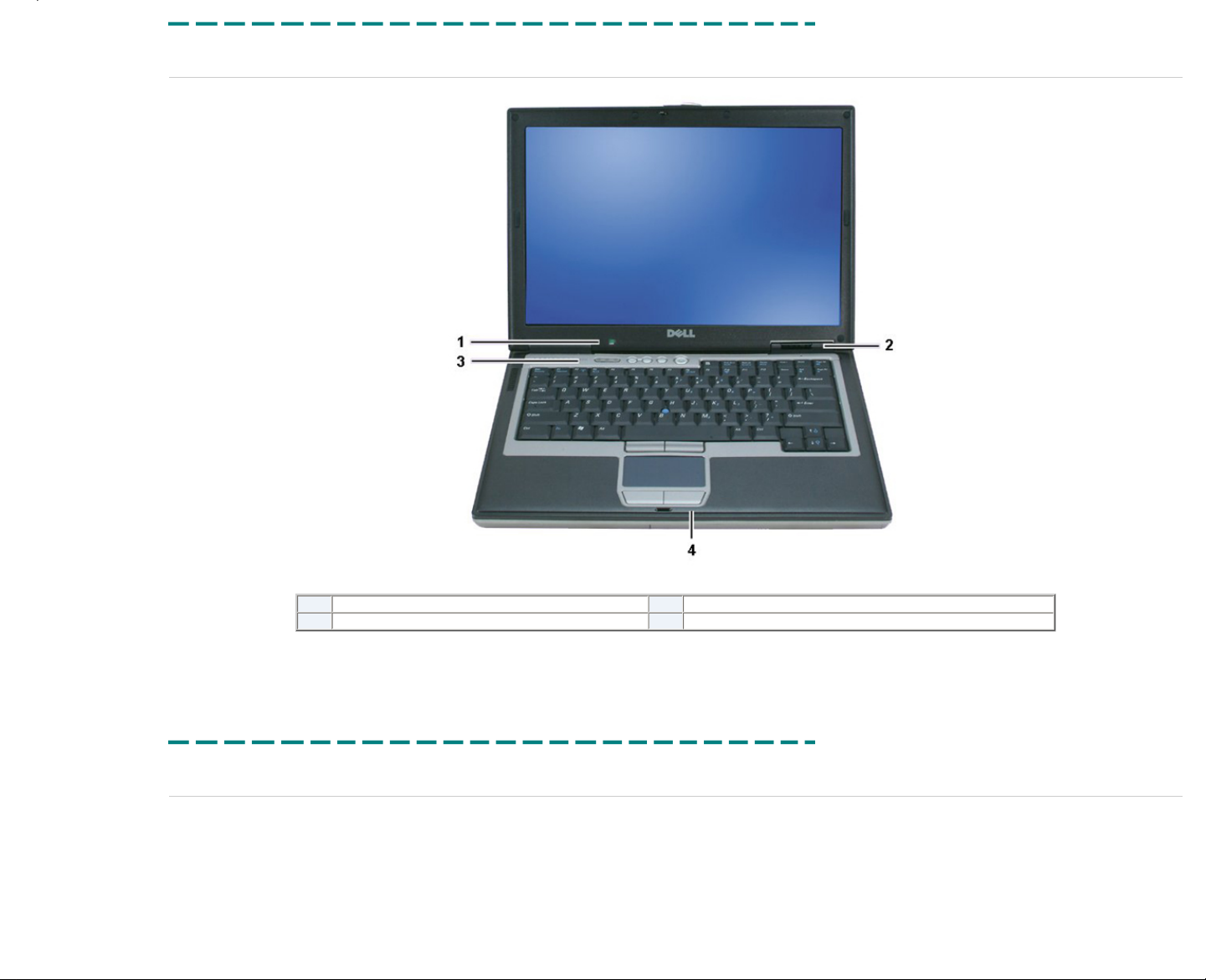
Chassis Front
Click the picture above to see a larger image in a new window.
1
Ambient light sensor (ALS)
3
Keyboard LEDs / audio controls
2
Status LEDs
4
Touch pad
Printed 2/22/2007 5:44:33 PM Latitude™ D620 For Dell Employees Only
Expires 2/23/2007 5:44:33 PM Chassis Front This document is Dell Confidential
Chassis Left
Page 12
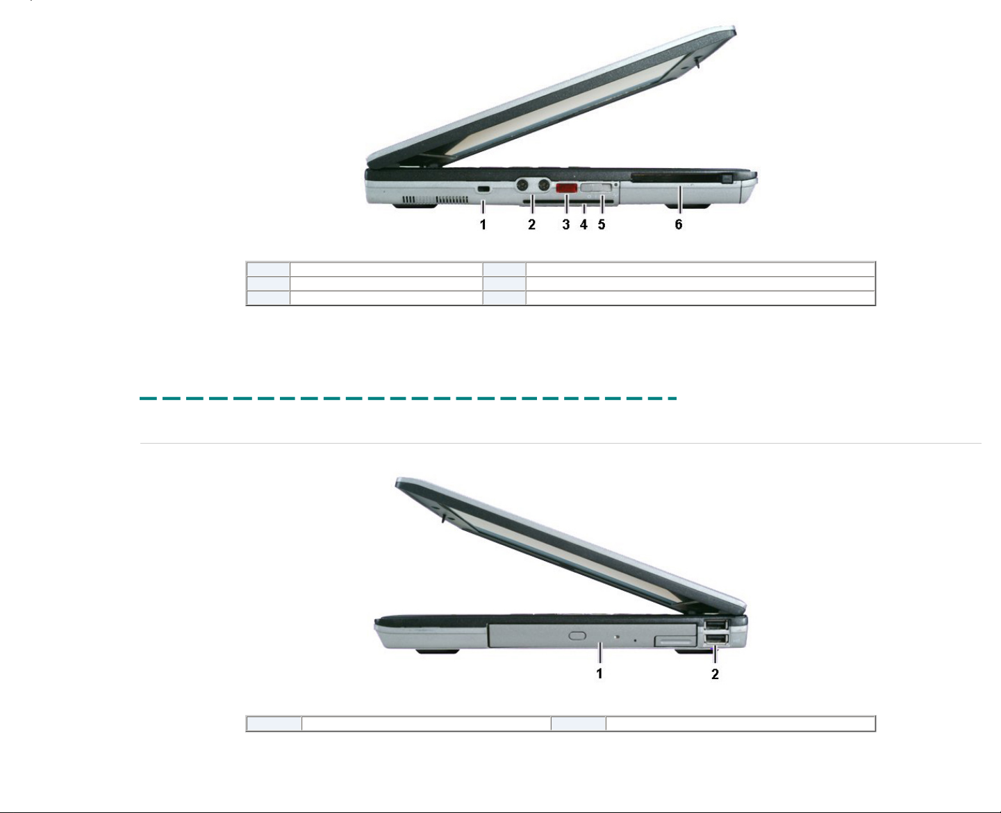
Click the picture above to see a larger image in a new window.
1
Security slot
4
Smart card reader
2
Audio jacks
5
Wireless catcher switch
3
Infrared port
6
PC Card™ slot
Printed 2/22/2007 5:44:33 PM Latitude™ D620 For Dell Employees Only
Expires 2/23/2007 5:44:33 PM Chassis Left This document is Dell Confidential
Chassis Right
Click the picture above to see a larger image in a new window.
1
Optical drive
2
USB ports (2)
Printed 2/22/2007 5:44:33 PM Latitude™ D620 For Dell Employees Only
Expires 2/23/2007 5:44:33 PM Chassis Right This document is Dell Confidential
Page 13
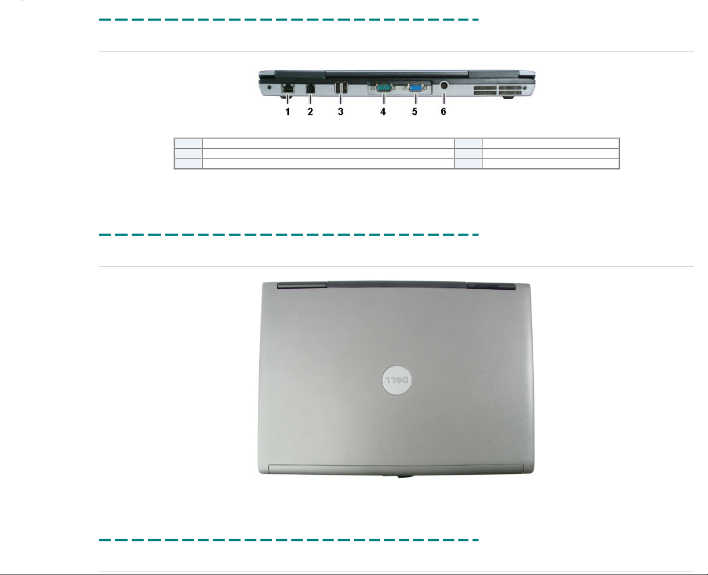
Chassis Back
Click the picture above to see a larger image in a new window.
1
RJ-45 (network) connector
4
Serial port
2
RJ-11 (modem) connector
5
VGA port
3
USB ports (2)
6
AC connector
Printed 2/22/2007 5:44:33 PM Latitude™ D620 For Dell Employees Only
Expires 2/23/2007 5:44:33 PM Chassis Back This document is Dell Confidential
Chassis Top
Click the picture above to see a larger image in a new window.
Printed 2/22/2007 5:44:33 PM Latitude™ D620 For Dell Employees Only
Expires 2/23/2007 5:44:33 PM Chassis Top This document is Dell Confidential
9-Cell Chassis Front
Page 14
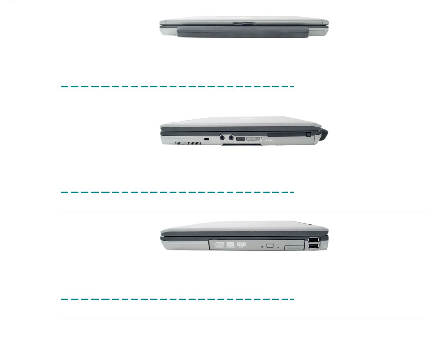
Click the picture above to see a larger image in a new window.
Printed 2/22/2007 5:44:33 PM Latitude™ D620 For Dell Employees Only
Expires 2/23/2007 5:44:33 PM 9-Cell Chassis Front This document is Dell Confidential
9-Cell Chassis Left
Click the picture above to see a larger image in a new window.
Printed 2/22/2007 5:44:33 PM Latitude™ D620 For Dell Employees Only
Expires 2/23/2007 5:44:33 PM 9-Cell Chassis Left This document is Dell Confidential
9-Cell Chassis Right
Click the picture above to see a larger image in a new window.
Printed 2/22/2007 5:44:33 PM Latitude™ D620 For Dell Employees Only
Expires 2/23/2007 5:44:33 PM 9-Cell Chassis Right This document is Dell Confidential
9-Cell Chassis Top
Page 15
Click the picture above to see a larger image in a new window.
Printed 2/22/2007 5:44:33 PM Latitude™ D620 For Dell Employees Only
Expires 2/23/2007 5:44:33 PM 9-Cell Chassis Top This document is Dell Confidential
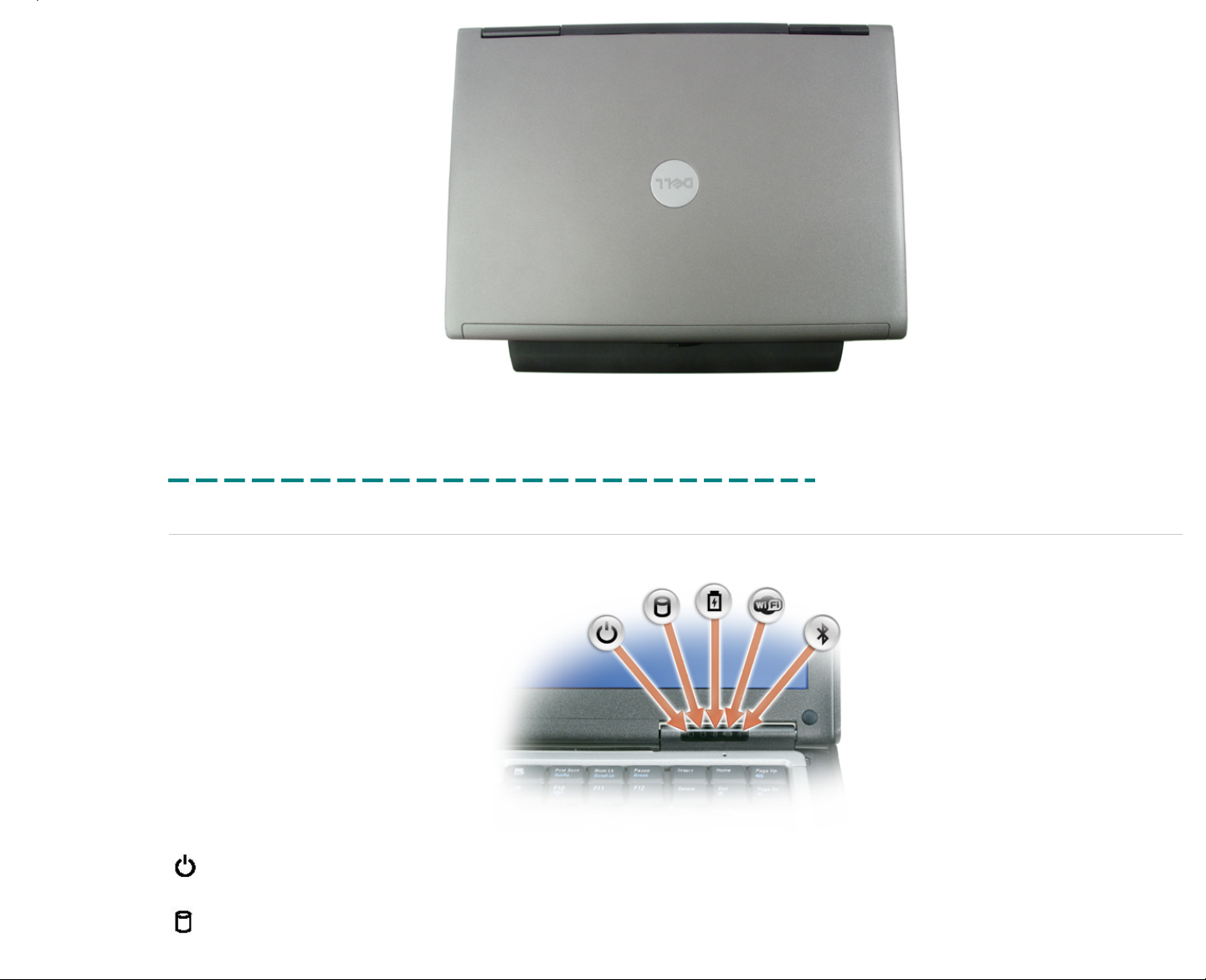
LEDs
Device Status LEDs
Turns on when you turn on the computer and blinks when the computer is in a power management mode.
Turns on when the computer reads or writes data.
Page 16
Turns on steadily or blinks to indicate battery charge status.
Turns on when wireless networking is enabled. To enable or disable wireless networking, press <Fn><F2>.
Turns on when a card with Bluetooth® wireless technology is enabled. To turn off only the Bluetooth wireless technology functionality, right-click the icon in
the system tray and select Disable Bluetooth Radio. To quickly enable or disable all wireless devices, press <Fn><F2>.
Battery Status
If the computer is connected to an electrical outlet, the battery light operates as follows:
● Solid green — The battery is charging.
● Flashing green — The battery is almost fully charged.
If the computer is running on a battery, the battery light operates as follows:
● Off — The battery is adequately charged (or the computer is turned off).
● Flashing orange — The battery charge is low.
● Solid orange — The battery charge is critically low.
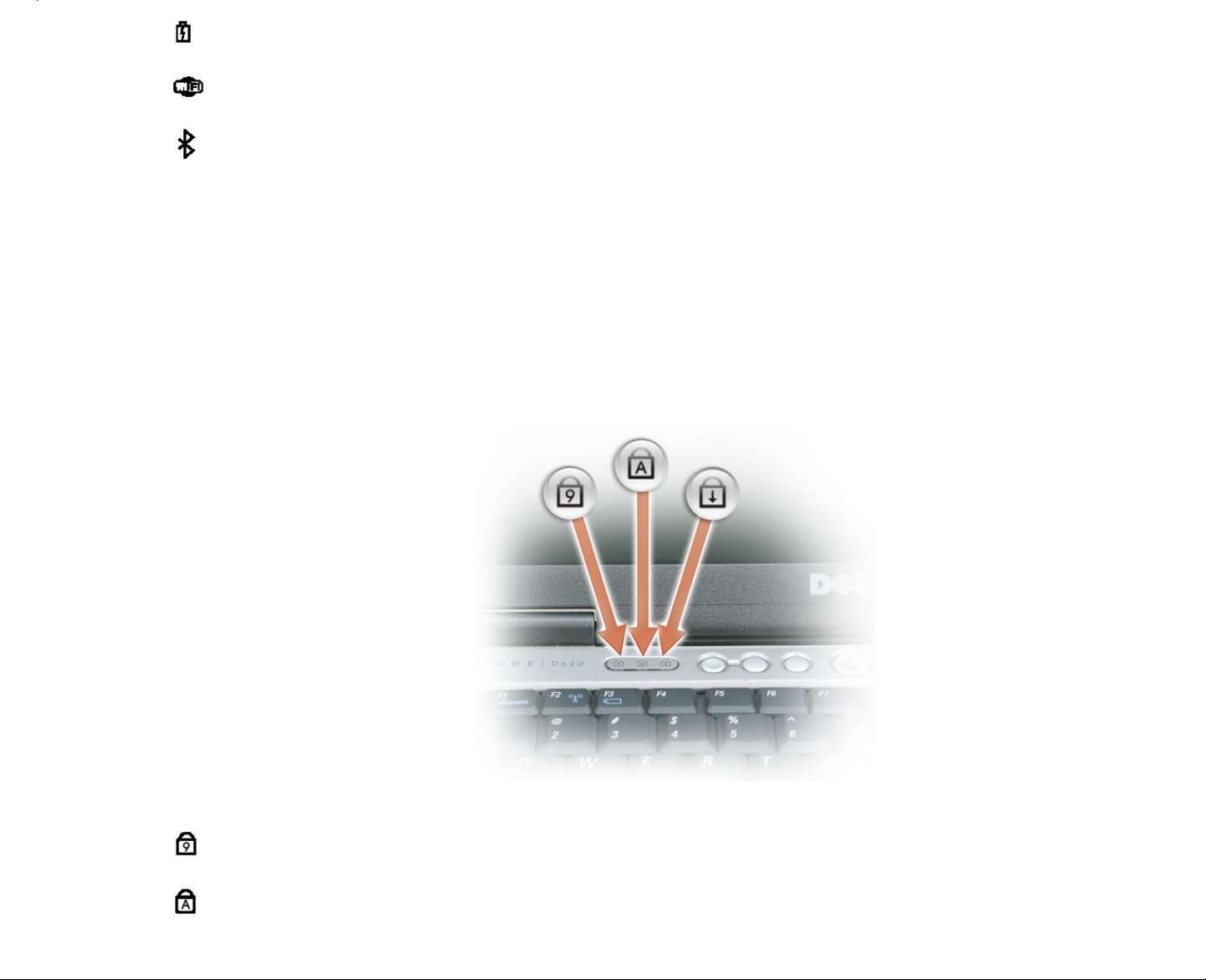
Keyboard Status LEDs
The green lights located above the keyboard indicate the following:
Turns on when the numeric keypad is enabled.
Turns on when the Caps Lock function is enabled.
Page 17
Turns on when the Scroll Lock function is enabled.
Printed 2/22/2007 5:44:33 PM Latitude™ D620 For Dell Employees Only
Expires 2/23/2007 5:44:33 PM LEDs This document is Dell Confidential
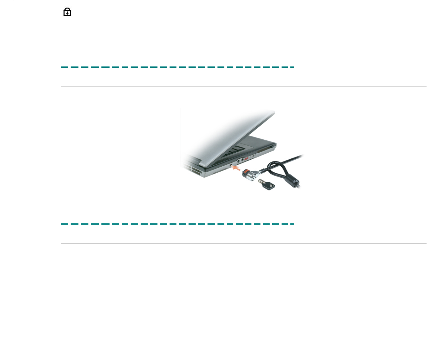
Security Slot
On the left side of the Latitude D620 system is a security slot, sometimes called a Kensington® lock slot. Connect a security cable to this slot to secure the notebook to a desk. The most popular security cables are made by
Kensington, but more companies are entering this marketplace.
Printed 2/22/2007 5:44:33 PM Latitude™ D620 For Dell Employees Only
Expires 2/23/2007 5:44:33 PM Security Slot This document is Dell Confidential
Safety Precautions
Observe the following safety precautions before performing any installation or break/fix procedures involving disassembly or re-assembly:
● Turn off the system and any attached peripherals.
● Disconnect the system and any attached peripherals from AC power, and then remove the battery.
● Disconnect any telephone or telecommunications lines from the system.
● Use a wrist grounding strap and mat when working inside any computer system to avoid electrostatic discharge (ESD) damage.
● After removing any system component, carefully place the removed component on an anti-static mat.
● Wear shoes with non-conductive rubber soles to help reduce the chance of being shocked or seriously injured in an electrical accident.
Standby Power
Dell products with standby power must be completely unplugged before opening the case. Systems that incorporate standby power are essentially powered while turned off. The internal power allows the system to be remotely turned
on (wake on LAN), suspended into a sleep mode, and have other advanced power management features. After unplugging the system, allow the charge to drain from the circuits by waiting approximately 30 to 45 seconds before
removing components.
ESD
ESD is a major concern when handling components, especially expansion cards and system boards. Very slight charges can damage circuits in ways that may not be obvious, such as intermittent problems or a shortened product
lifespan.
Page 18

WARNING:
Do not use an ESD grounding strap when working on the internal parts of a monitor, like the CRT, because the stored voltage is extremely harmful.
To prevent static damage, do the following:
● Use an ESD wrist strap that is properly grounded.
● If a strap is not available, discharge static electricity from your body before you touch any of your computer's electronic components, by touching an unpainted metal surface on the computer chassis. Periodically touch an
unpainted metal surface to remove any static charge your body may have accumulated.
● Handle all static-sensitive components in a static-safe area. If possible, use anti-static floor pads and workbench pads.
● When handling static-sensitive components, grab them by the sides, not the top. Avoid touching pins and circuit boards.
● When unpacking a static-sensitive component from its shipping carton, do not remove the component from the anti-static packing material until you are ready to install the component. Before unwrapping the anti-static
packaging, be sure to discharge static electricity from your body.
● Before transporting a static-sensitive component, place it in an anti-static container or packaging.
Lifting Equipment
CAUTION:
Do not lift greater than 50 pounds independently. Always obtain assistance from a second person or utilize a mechanical lifting device.
Adhere to the following guidelines when lifting equipment:
1. Get a firm balanced footing. Keep your feet apart for a stable base, and point your toes out.
2. Bend your knees. Do not bend at the waist.
3. Tighten stomach muscles. Abdominal muscles support your spine when you lift, offsetting the force of the load.
4. Lift with your legs, not your back.
5. Keep the load close. The closer it is to your spine, the less force it exerts on your back.
6. Keep your back upright, whether lifting or setting down the load. Do not add the weight of your body to the load. Avoid twisting your body and back.
7. Follow the same techniques in reverse to set the load down.
Printed 2/22/2007 5:44:33 PM Latitude™ D620 For Dell Employees Only
Expires 2/23/2007 5:44:33 PM Safety Precautions This document is Dell Confidential
Service Issues
You need to address the following issues when replacing parts on the Latitude™ D620.
Palm Rest Removal
The palm rest on this system needs to be removed in a certain manner. Follow these steps:
1. Remove all parts necessary to access the palm rest.
2. Remove the nine securing screws from the bottom section of the system.
3. Remove the three palm rest screws from the upper section of the system.
4. Disconnect the cable connector attached to the system board located on the left side of the system.
5. Starting with the back of the palm rest (located near the LCD mounts), separate the palm rest from the base of the system, and work it loose along the sides towards the front.
Page 19
WARNING:
You must start removing the palm rest from the back. Failure to do so will damage the connector hooks located along the front edge of the base plastics.
6. Once the back and sides of the palm rest are free, slide it forward to release it from the securing hooks located along the front edge of the base plastics.
7. Remove the palm rest from the system.
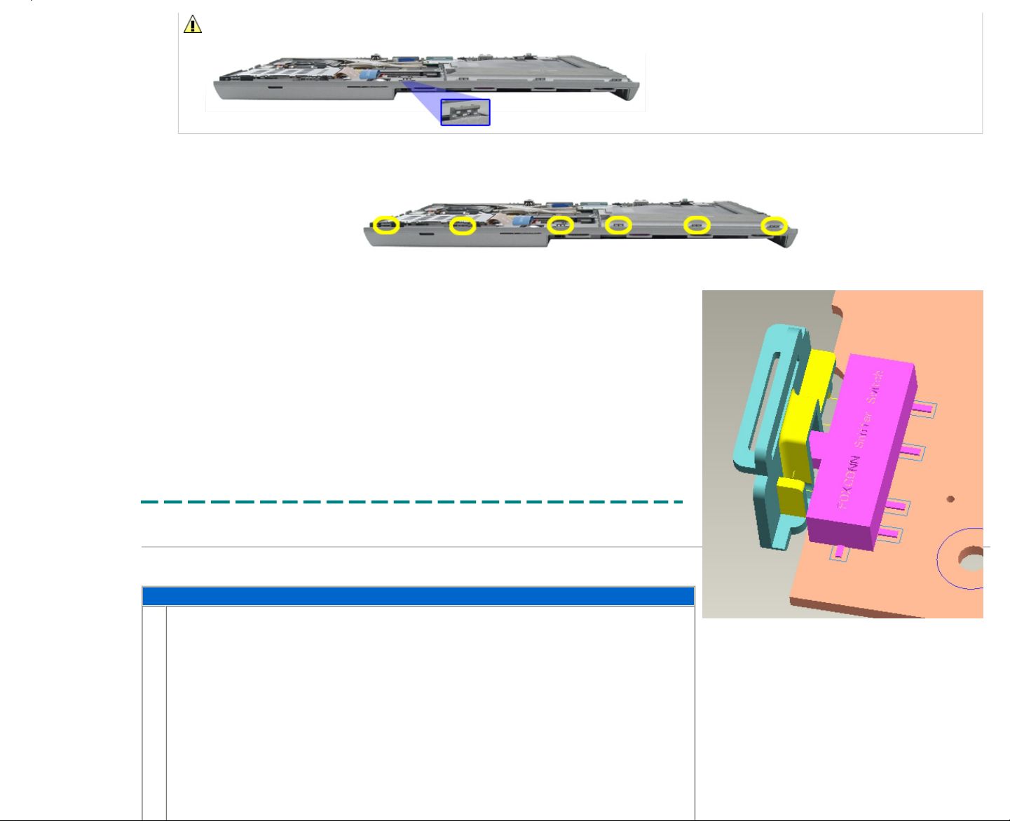
System Board Replacement
The system board removal is straightforward. However, replacing it correctly involves lining up the wireless sniffer switch correctly, or the board does
not seat properly in the system.
When you reseat the system board, the wireless switch must line up with the plastics as shown to the right. If it is not lined up correctly, the board does
not seat down fully and hangs over the right edge of the bottom plastics. At no point should you force the board into place; this will damage the plastics,
the switch, or worse.
The easiest method of aligning the switch with the plastics is to have both the interior switch on the system board as well as the exterior switch on the
outer plastics in the "off" position, all the way towards the back of the unit (closest to the LCD).
Printed 2/22/2007 5:44:33 PM Latitude™ D620 For Dell Employees Only
Expires 2/23/2007 5:44:33 PM Service Issues This document is Dell Confidential
AC Power
The following table outlines the steps for removing and replacing the AC power converter for the Latitude™ D620.
Disconnecting the AC Power Converter
1.
Pull the AC plug from the left side of the system.
Page 20
2.
Reverse the previous step to replace the AC power converter.
Printed 2/22/2007 5:44:33 PM Latitude™ D620 For Dell Employees Only
Expires 2/23/2007 5:44:33 PM AC Power This document is Dell Confidential
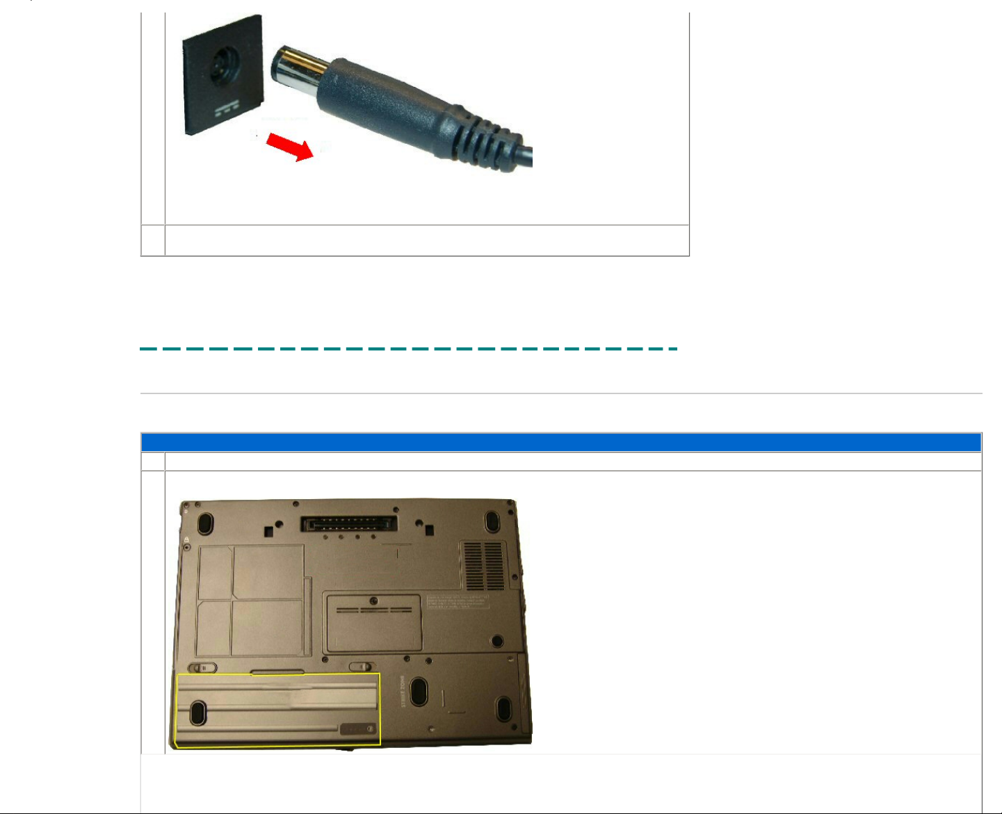
Battery
The following table outlines the steps for removing and replacing the battery on the Latitude™ D620.
Removing and Replacing the Battery
1.
Before removing the battery, remove the AC power.
2.
Locate the battery.
Page 21
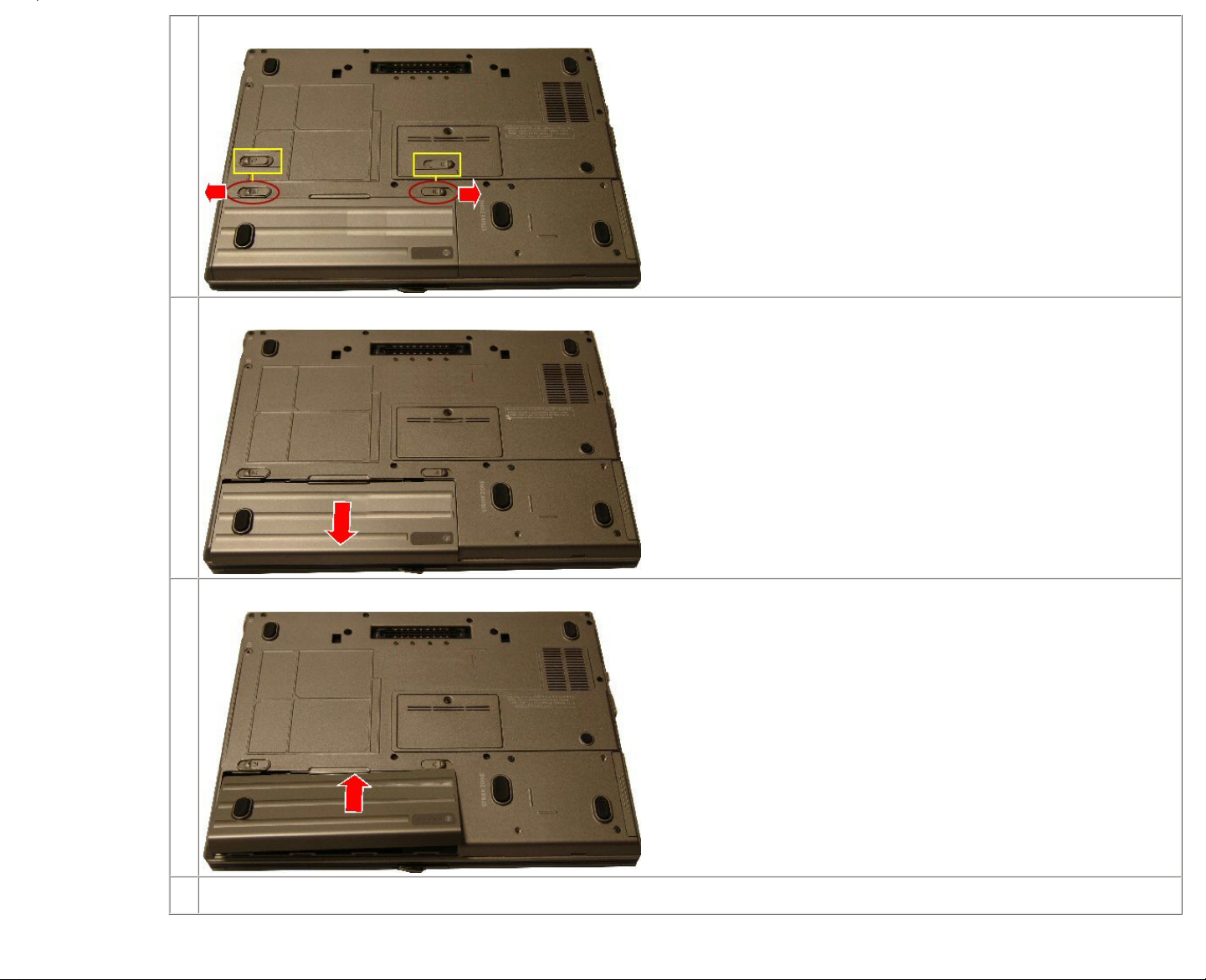
3.
Slide the battery release latch into the unlock position.
4.
Slide the battery from the bay.
5.
Lift the battery pack out from the bay.
6.
Reverse the previous steps to replace the battery.
Printed 2/22/2007 5:44:33 PM Latitude™ D620 For Dell Employees Only
Page 22
Expires 2/23/2007 5:44:33 PM Battery This document is Dell Confidential
Phone SIM
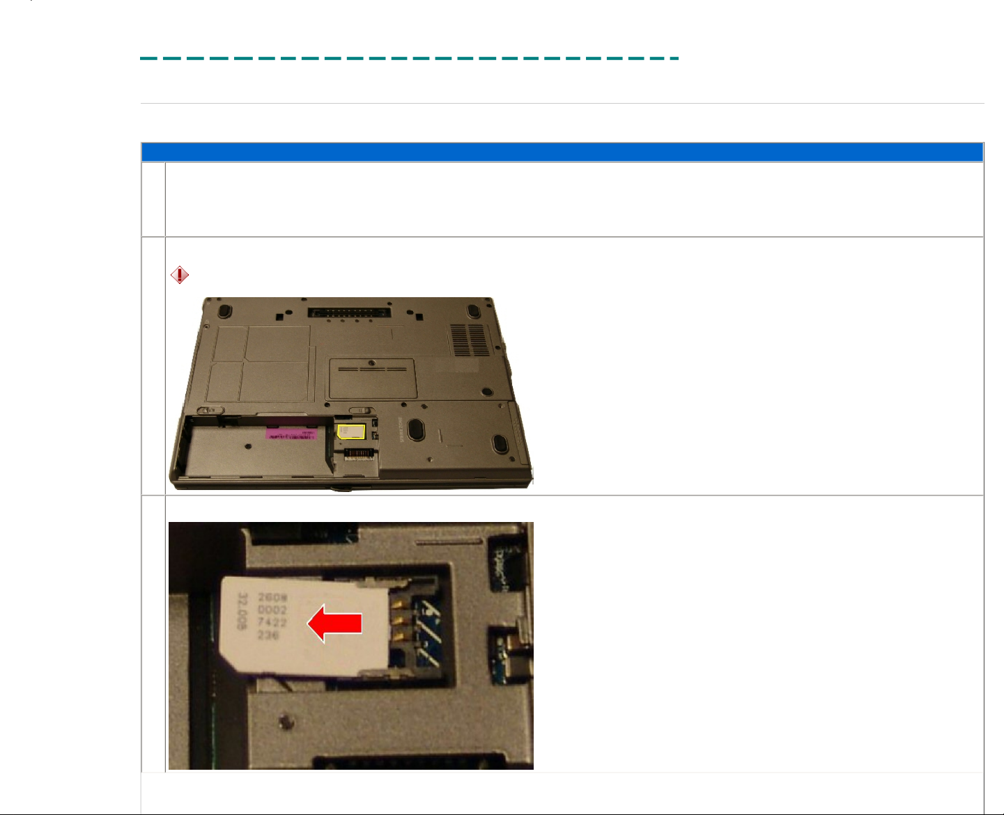
The following table outlines the steps for removing and replacing the phone SIM (subscriber identity module) for the Latitude™ D620.
Removing and Replacing the Phone SIM
1.
Before removing the SIM:
● Remove the AC power.
● Remove the battery.
2.
Locate the phone SIM in the battery bay.
CAUTION:
The customer's SIM contains account information and personal data not backed up to any media. When repairing a system, you must migratee this card when replacing a system
board.
3.
Slide the module from the slot reader.
Page 23
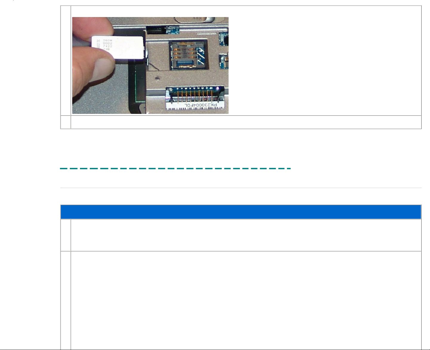
4.
Lift the module from the system.
5.
Reverse the previous steps to replace the phone SIM.
Printed 2/22/2007 5:44:33 PM Latitude™ D620 For Dell Employees Only
Expires 2/23/2007 5:44:33 PM Phone SIM This document is Dell Confidential
Memory DIMM B
The following table outlines the steps for removing and replacing the memory in DIMM B on the Latitude™ D620.
Removing and Replacing the Memory in DIMM B
1.
Before removing the memory in DIMM B:
● Remove the AC power.
● Remove the battery.
2.
Locate the memory door on the bottom of the system.
Page 24
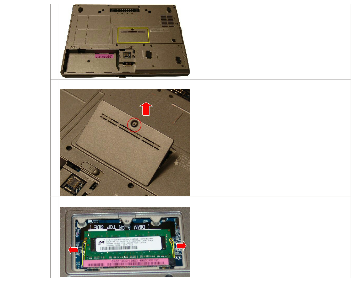
3.
Use a Phillips screwdriver to remove the screw securing the memory door, and then lift the door to remove it.
4.
Push outward on the retaining clips to allow the memory to release upward.
Page 25
5.
Lift and remove the memory from the socket.
6.
Remove the memory from the socket.
7.
Reverse the previous steps to replace the memory in DIMM B.
Printed 2/22/2007 5:44:33 PM Latitude™ D620 For Dell Employees Only
Expires 2/23/2007 5:44:33 PM Memory DIMM B This document is Dell Confidential
Optical Drive
The following table outlines the steps for removing and replacing the optical drive.
Page 26
Removing and Replacing the Optical Drive
1.
Before removing the optical drive:
● Remove the AC power.
● Remove the battery.
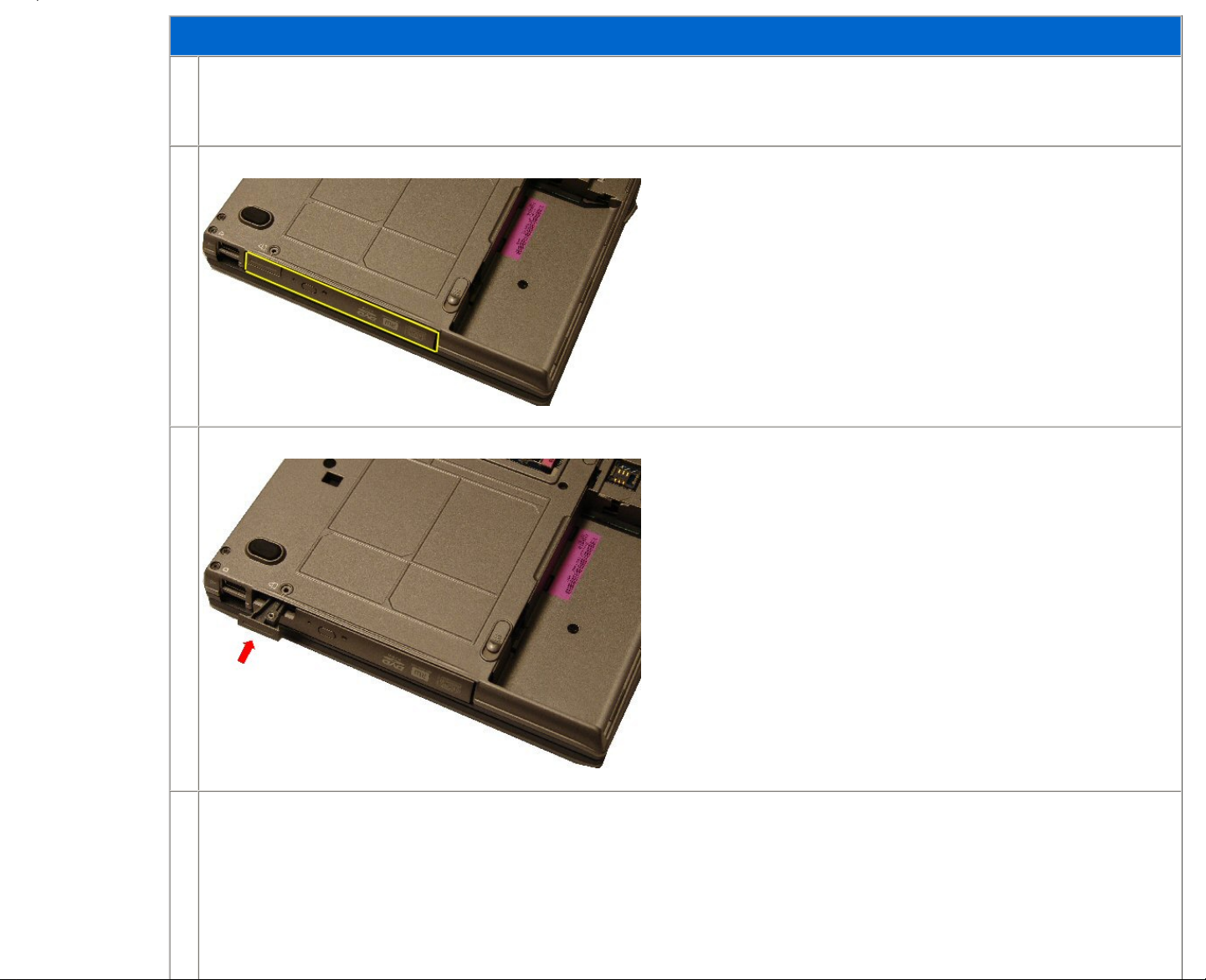
2.
Locate the optical drive bay.
3.
Press the optical drive release button to eject the drive.
4.
Slide drive out of the optical drive bay.
Page 27
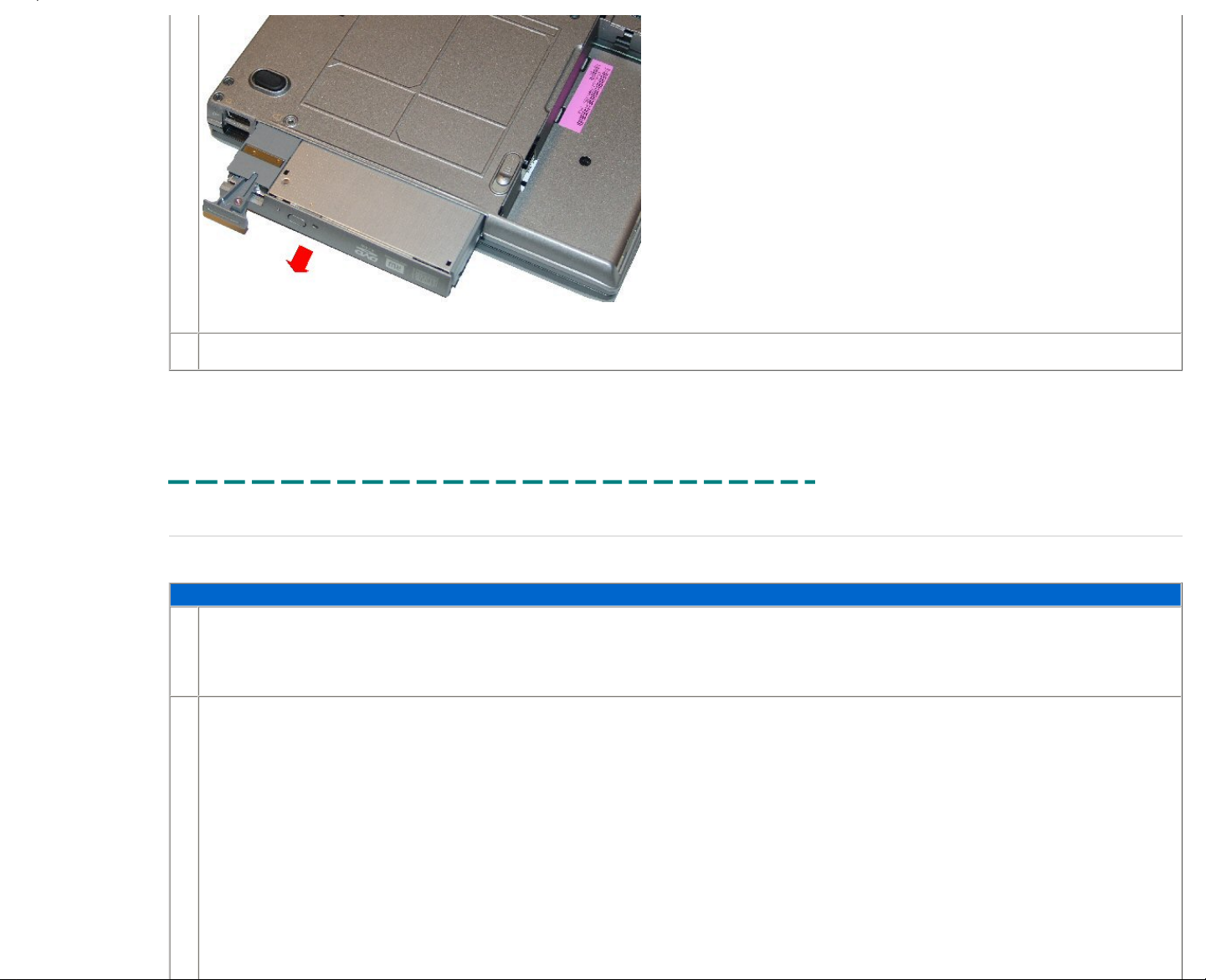
5.
Reverse the previous steps to replace the optical drive.
Printed 2/22/2007 5:44:33 PM Latitude™ D620 For Dell Employees Only
Expires 2/23/2007 5:44:33 PM Optical Drive This document is Dell Confidential
Hard Drive
The following table outlines the steps for removing and replacing the hard drive for the Latitude™ D620.
Removing and Replacing the Hard Drive
1.
Before removing the hard drive:
● Remove the AC power.
● Remove the battery.
2.
Locate the hard drive.
Page 28
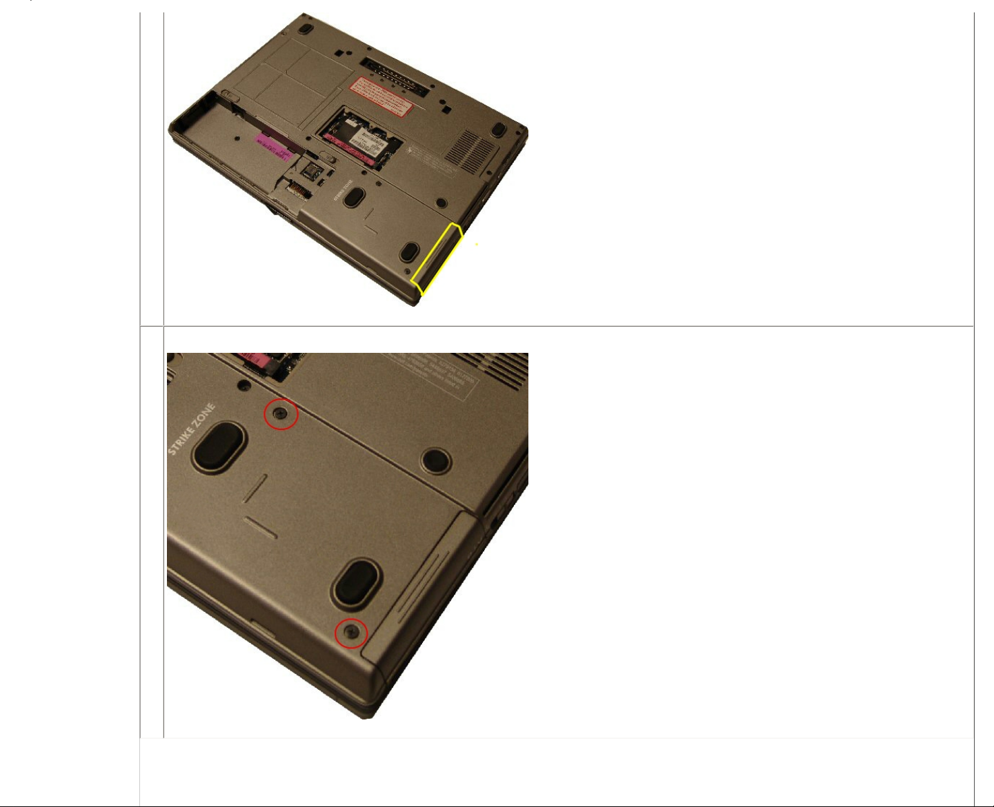
3.
Remove the two screws securing the drive.
Page 29
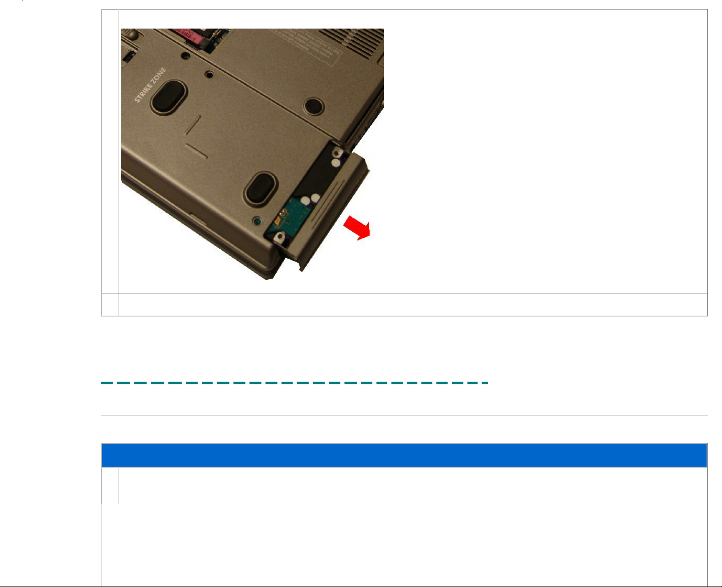
4.
Slide the hard drive out of the bay to release it from the system.
5.
Reverse the previous steps to replace the hard drive.
Printed 2/22/2007 5:44:33 PM Latitude™ D620 For Dell Employees Only
Expires 2/23/2007 5:44:33 PM Hard Drive This document is Dell Confidential
Hinge Cover
The following table outlines the steps for removing and replacing the hinge cover.
Removing and Replacing the Hinge Cover
1.
● Remove the AC power.
● Remove the battery.
Page 30
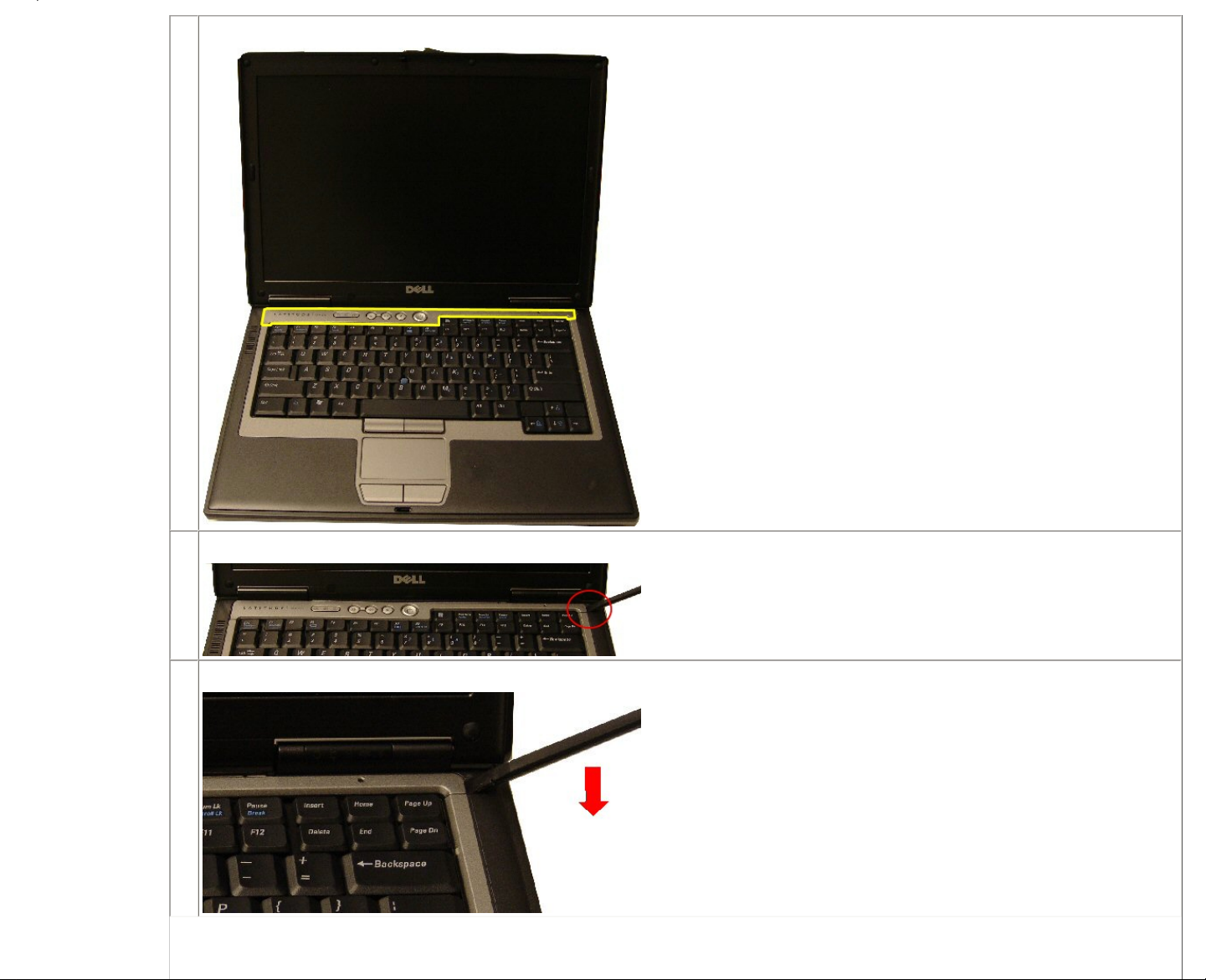
2.
Locate the hinge cover.
3.
Insert a scribe into the hinge cover slot.
4.
Pry up on the notch on the right side of the hinge cover.
Page 31

5.
Lift and remove the hinge cover from the chassis.
6.
Reverse the previous steps to replace the hinge cover.
Printed 2/22/2007 5:44:33 PM Latitude™ D620 For Dell Employees Only
Expires 2/23/2007 5:44:33 PM Hinge Cover This document is Dell Confidential
Keyboard
The following table outlines the steps for removing and replacing the keyboard for the Latitude™ D620.
Removing and Replacing the Keyboard
1.
Before removing the keyboard:
● Remove the AC power.
● Remove the battery.
● Remove the hinge cover.
2.
Locate the keyboard.
Page 32

3.
Remove the screws holding the keyboard to the chassis.
4.
Lift the keyboard and turn it away from the LCD.
5.
Release the keyboard cable lock.
Page 33

6.
Release the ZIF connector to detach the cable and lift the keyboard from the system.
7.
Reverse the previous steps to replace the keyboard.
Printed 2/22/2007 5:44:33 PM Latitude™ D620 For Dell Employees Only
Expires 2/23/2007 5:44:33 PM Keyboard This document is Dell Confidential
Bluetooth Card
Page 34

The following table outlines the steps for removing and replacing the Bluetooth® card for the Latitude™ D620.
Removing and Replacing the Bluetooth Card
1.
Before removing the Bluetooth card:
● Remove the AC power.
● Remove the battery.
● Remove the hinge cover.
● Remove the keyboard.
2.
Locate the Bluetooth wireless card.
3.
Insert a scribe to release the clip holding the card.
Page 35

4.
Slide the Bluetooth wireless card away from the LCD.
5.
Lift the Bluetooth wireless card from the system.
6.
Disconnect the Bluetooth wireless card cable.
Page 36

7.
Reverse the previous steps to replace the Bluetooth wireless card.
Printed 2/22/2007 5:44:33 PM Latitude™ D620 For Dell Employees Only
Expires 2/23/2007 5:44:33 PM Bluetooth Card This document is Dell Confidential
Coin Battery
The following table outlines the steps for removing and replacing the coin battery for the Latitude™ D620.
Removing and Replacing the Coin Battery
1.
Before removing the coin battery:
● Remove the AC power.
● Remove the battery.
● Remove the hard drive.
● Remove the hinge cover.
● Remove the keyboard.
2.
Locate the coin battery.
3.
Slide the coin battery away from the LCD.
Page 37

4.
Disconnect the cable connection and lift the coin battery from the system.
5.
Reverse the previous steps to replace the coin battery.
Printed 2/22/2007 5:44:33 PM Latitude™ D620 For Dell Employees Only
Expires 2/23/2007 5:44:33 PM Coin Battery This document is Dell Confidential
Memory DIMM A
The following table outlines the steps for removing and replacing the memory for the Latitude™ D620.
Removing and Replacing the Memory
Page 38

1.
Before removing the memory:
● Remove the AC power.
● Remove the battery.
● Remove the hinge cover.
● Remove the keyboard.
2.
Locate the memory DIMM.
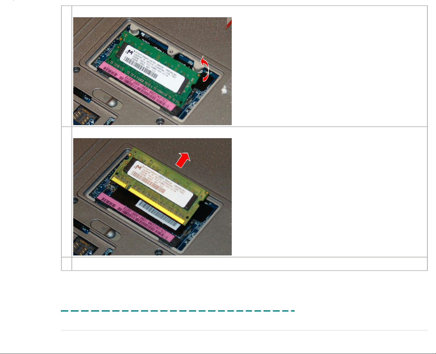
3.
Press out on the latches on both sides of the DIMM socket.
4.
Pull the memory upward to a 45-degree angle.
Page 39

5.
Remove the DIMM module from the socket.
6.
Reverse the previous steps to replace the memory.
Printed 2/22/2007 5:44:33 PM Latitude™ D620 For Dell Employees Only
Expires 2/23/2007 5:44:33 PM Memory DIMM A This document is Dell Confidential
WWAN Card
The following table outlines the steps for removing and replacing the WWAN card on the Latitude™ D620.
Page 40

Removing and Replacing the WWAN Card
1.
Before removing the WWAN card:
● Remove the AC power.
● Remove the battery.
● Remove the hinge cover.
● Remove the keyboard.
● Remove the memory DIMM A.
2.
Locate the WWAN card.
3.
Disconnect the two cables from the WWAN card.
Page 41

4.
Pull the two securing levers away from the WWAN card, and then remove the card.
Page 42

5.
Lift the WWAN card to a 45-degree angle.
Page 43

6.
Lift the WWAN card out of the slot.
Page 44

7.
Reverse the previous steps to replace the WWAN card.
Printed 2/22/2007 5:44:33 PM Latitude™ D620 For Dell Employees Only
Expires 2/23/2007 5:44:33 PM WWAN Card This document is Dell Confidential
WLAN Card
The following table outlines the steps for removing and replacing the WLAN card on the Latitude™ D620.
Removing and Replacing the WLAN Card
1.
Before removing the WLAN card:
● Remove the AC power.
● Remove the battery.
● Remove the hinge cover.
● Remove the keyboard.
2.
Locate the WLAN card.
3.
Disconnect the two diversity cables from the mini card.
NOTE:
There are three cables for the wireless card. The third cable is for the new wireless standard not yet approved. However, this system can use the new technology when it is
approved.
Page 45

4.
Pull the two securing levers away from the card, and then remove the card.
5.
Lift the WLAN card to a 45-degree angle.
Page 46

6.
Lift the WLAN card out of the slot.
7.
Reverse the previous steps to replace the WLAN card.
Printed 2/22/2007 5:44:33 PM Latitude™ D620 For Dell Employees Only
Expires 2/23/2007 5:44:33 PM WLAN Card This document is Dell Confidential
LCD Removal
The following table outlines the steps for removing and replacing the LCD for the Latitude™ D620.
Page 47

Removing and Replacing the LCD
1.
Before removing the LCD:
● Remove the AC power.
● Remove the battery.
● Remove the hinge cover.
● Remove the keyboard.
2.
Locate the LCD.
3.
Disconnect all cables to the WWAN and WLAN cards if necessary.
Page 48

4.
Disconnect the video cable from the chassis.
5.
Remove the four hinge screws from the back and bottom of the chassis.
6.
Lift the LCD from the frame.
7.
Reverse the previous steps to replace the LCD.
Page 49

Printed 2/22/2007 5:44:33 PM Latitude™ D620 For Dell Employees Only
Expires 2/23/2007 5:44:33 PM LCD Removal This document is Dell Confidential
LCD Disassembly
The following table outlines the steps for disassembling the LCD on the Latitude D620.
Disassembling the LCD
1.
Before disassembling the LCD:
● Remove the AC power.
● Remove the battery.
● Remove the phone SIM.
● Remove the memory DIMM B.
● Remove the optical drive.
● Remove the hard drive.
● Remove the hinge cover.
● Remove the keyboard.
● Remove the Bluetooth® card.
● Remove the coin battery.
● Remove the memory DIMM A.
● Remove the WWAN card.
● Remove the WLAN card.
● Remove the LCD.
2.
Locate the LCD.
Page 50

3.
Remove the bumpers covering the screws.
4.
Remove the six screws.
5.
Push the LCD bezel in from the outside frame to release, then up and lift it off the frame.
Page 51

6.
Remove the eight frame screws from the LCD brackets.
7.
Lift the LCD from the LCD backing.
Page 52

8.
Rotate the LCD to access the LCD cable on the back of the LCD.
Page 53

9.
Push in on the top LCD cable levers to release the cable connection, and then pull up on the bottom connection to release the cable.
10.
Remove the LCD brackets from the LCD.
NOTE:
When replacing the LCD, you must migrate the two brackets to the replacement
LCD.
11.
Slide the LCD brackets from the LCD.
Page 54

12.
Reverse the previous steps to assemble the LCD.
Printed 2/22/2007 5:44:33 PM Latitude™ D620 For Dell Employees Only
Expires 2/23/2007 5:44:33 PM LCD Disassembly This document is Dell Confidential
Palm Rest
The following table outlines the steps for removing and replacing the palm rest assembly for the Latitude™ D620.
Removing and Replacing the Palm Rest Assembly
1.
Before removing the palm rest assembly:
● Remove the AC power.
● Remove the battery.
● Remove the optical drive.
● Remove the hard drive.
● Remove the hinge cover.
● Remove the keyboard.
● Remove the Bluetooth® card.
● Remove the coin battery.
● Remove the LCD.
2.
Locate the palm rest
3.
Remove the nine securing screws from the bottom section of the system.
Page 55

4.
Remove the three palm rest screws from the upper section of the system for the Latitude D620.
5.
Disconnect the cable connector attached to the system board.
Page 56

6.
Lift the palm rest up from the chassis and remove it.
7.
Reverse the previous steps to replace the palm rest assembly.
Printed 2/22/2007 5:44:33 PM Latitude™ D620 For Dell Employees Only
Expires 2/23/2007 5:44:33 PM Palm Rest This document is Dell Confidential
Modem Daughter Card
The following table outlines the steps for removing and replacing the modem daughter card (MDC) for the Latitude™ D620.
Removing and Replacing the MDC
1.
Before removing the MDC:
● Remove the AC power.
● Remove the battery.
● Remove the optical drive.
● Remove the hard drive.
● Remove the hinge cover.
● Remove the keyboard.
● Remove the Bluetooth® card.
● Remove the LCD removal.
● Remove the palm rest assembly.
Page 57

2.
Locate the MDC card.
3.
Remove the screw securing the MDC to the system board.
4.
Lift the MDC from the system board.
Page 58

■ Graphics Overview
■ Intel GMA 950
■ NVIDIA Quadro NVS 110M
■ NVIDIA Quadro NVS
110M Overview
■ NVIDIA Installation
■ NVIDIA Connections
■ NVIDIA Using the
Software
■ NVIDIA Troubleshooting
■ NVIDIA Specifications
5.
Disconnect the cable from the MDC and remove it from the system.
6.
Reverse the previous steps to replace the MDC.
Printed 2/22/2007 5:44:33 PM Latitude™ D620 For Dell Employees Only
Expires 2/23/2007 5:44:33 PM Modem Daughter Card This document is Dell Confidential
Processor
The following table outlines the steps for removing and replacing the processor for the Latitude™ D620.
Removing and Replacing the Processor
Page 59

1.
Before removing the processor:
● Remove the AC power.
● Remove the battery.
● Remove the phone SIM.
● Remove the memory DIMM B.
● Remove the optical drive.
● Remove the hard drive.
● Remove the hinge cover.
● Remove the keyboard.
● Remove the Bluetooth® card.
● Remove the coin battery.
● Remove the memory DIMM A.
● Remove the WWAN card.
● Remove the WLAN card.
● Remove the LCD.
● Remove the palm rest assembly.
● Remove the modem daughter card.
2.
Locate the processor heat sink.
3.
Remove the four screws that secure the processor to the system board.
Page 60

4.
Lift the heat sink away from the system.
5.
Locate the processor.
6.
Turn the screw that secures the processor to the system board.
Page 61

7.
Lift the processor from system.
8.
Reverse the previous steps to replace the processor.
Printed 2/22/2007 5:44:33 PM Latitude™ D620 For Dell Employees Only
Expires 2/23/2007 5:44:33 PM Processor This document is Dell Confidential
Speaker
The following table outlines the steps for removing and replacing the speaker for the Latitude™ D620.
Removing and Replacing the Speaker
1.
Before removing the speaker:
● Remove the AC power.
● Remove the battery.
● Remove the phone SIM.
● Remove the memory DIMM B.
● Remove the optical drive.
● Remove the hard drive.
● Remove the hinge cover.
● Remove the keyboard.
● Remove the Bluetooth® card.
● Remove the coin battery.
● Remove the memory DIMM A.
● Remove the WWAN card.
● Remove the WLAN card.
● Remove the LCD.
● Remove the palm rest assembly.
● Remove the modem daughter card.
● Remove the processor.
Page 62

2.
Locate the speaker.
3.
Disconnect the speaker cable from the system board.
4.
Lift the speaker from the system.
5.
Reverse the previous steps to replace the speaker.
Page 63

Printed 2/22/2007 5:44:33 PM Latitude™ D620 For Dell Employees Only
Expires 2/23/2007 5:44:33 PM Speaker This document is Dell Confidential
System Board
The following table outlines the steps for removing and replacing the system board.
Removing and Replacing the System Board
1.
Before removing the system board:
● Remove the AC power.
● Remove the battery.
● Remove the phone SIM.
● Remove the memory DIMM B.
● Remove the optical drive.
● Remove the hard drive.
● Remove the hinge cover.
● Remove the keyboard.
● Remove the Bluetooth® card.
● Remove the coin battery.
● Remove the memory DIMM A.
● Remove the WWAN card.
● Remove the WLAN card.
● Remove the LCD.
● Remove the palm rest assembly.
● Remove the modem daughter card.
● Remove the processor.
● Remove the fan.
2.
Locate the system board.
Page 64

3.
Dissconnect the speaker cable and modem cables from the system board.
4.
Disconnect the card cage cable from the system board.
5.
Lift the speaker from the system board.
Page 65

6.
Remove the Hex nuts on the back from the system.
7.
Lift the system board from the bottom plastics.
8.
Reverse the previous steps to replace the system board.
Printed 2/22/2007 5:44:33 PM Latitude™ D620 For Dell Employees Only
Expires 2/23/2007 5:44:33 PM System Board This document is Dell Confidential
Fan
The following table outlines the steps for removing and replacing the fan for the Latitude™ D620.
Removing and Replacing the Fan
1.
Before removing the fan:
● Remove the AC power.
● Remove the battery.
● Remove the phone SIM.
● Remove the memory DIMM B.
● Remove the optical drive.
● Remove the hard drive.
● Remove the hinge cover.
● Remove the keyboard.
● Remove the Bluetooth® card.
● Remove the coin battery.
● Remove the memory DIMM A.
● Remove the WWAN card.
● Remove the WLAN card.
● Remove the LCD.
● Remove the palm rest assembly.
● Remove the modem daughter card.
● Remove the processor.
Page 66

● Remove the system board.
2.
Locate the system fan.
3.
Remove the screw securing the fan to the system board.
4.
Lift the fan from the system.
Page 67

5.
Reverse the previous steps to replace the fan.
Printed 2/22/2007 5:44:33 PM Latitude™ D620 For Dell Employees Only
Expires 2/23/2007 5:44:33 PM Fan This document is Dell Confidential
Core Duo
Overview
Intel® Core™ Duo is the dual-core version of Intel's Pentium® M processor for notebooks. It is part of the new mobile technology offering from Intel code-named Napa. Unlike
Intel's first dual-core designs for desktop PCs, Intel Core Duo is a much more integrated design that shares storage and power management resources within the chip. Here is a
quick overview of what this new CPU offers:
● Intel's first dual-core optimized CPU
● 667 MHz front-side bus
● Built on new 65 nm technology
● Two mobile optimized execution cores in a single processor
● Parallel threads executed on separate cores with dedicated CPU resources
Intel also implements a host of new features into the new Intel Core Duo chip. These features include the following:
● Intel Smart Cache — This is an enhanced version of handling the L2 cache from the previous dual-core desktop processors that allows both cores to access the
same L2 cache.
● Intel Dynamic Power Coordination — This feature coordinates the power states between the two cores, enabling them to each individually step down activity as required.
● Intel Digital Media Boost — Digital Media Boost provides enhancements to gaming, video streaming, digital music and photography, as well as other multimedia applications.
● Intel Advanced Thermal Manager — New thermal sensors and management technology allows for enhanced accuracy with dual-core optimized thermal management.
● Intel Virtualization Technology — This delivers a hardware-assisted robust virtualization and manageability solution. Not supported on Dell™ systems at this time.
Page 68

L2 Cache
The desktop version dual-core Pentium D processor uses separate 1 MB cache memory banks dedicated to each core. In the Intel Core Duo processor, a single 2 MB
cache memory bank is available to both cores, reducing the chance that data must leave the chip to be temporarily stored in a system's main memory bank. This
means that one core can store a piece of data in the cache that might be needed later by the other core, and the other core can access that data without having to
leave the chip. The larger storage capacity allows Intel Core Duo processor's cores to spend less time navigating through the front side bus and more time executing
instructions, which dramatically improves performance.
The shared cache design also allows Intel to eliminate some of the disadvantages of its front side bus design, which many analysts see as a bottleneck in the dual-core
era. The front side bus is the connection between the processor and the main system memory via a chipset. On Intel's chips, this interface is located on the chipset,
farther away from the CPU. Intel plans eventually to move to a different design, but in the meantime it has been raising the speed at which its buses move data to cope
with the increased activity of two processor cores. Intel Core Duo processor's two cores share a single front-side bus running at 667 MHz.
Hyper-Threading vs. Dual-Core
Dual-Core processors provide a greater advantage over Hyper-Threading. In Hyper-Threading, parallel threads are executed on a single core using shared resources.
With the Dual-Core solution, parallel threads are executed on separate cores with dedicated resources. The following graphic helps explain this:
One execution core viewed as
two logical cores by software
Two execution cores
on a single processor
In rare instances, customers may experience a problem with some older applications that do not work with a dual-core processor. While dual-core operation should not cause a problem in most circumstances, customers either
experiencing errors with certain applications or random hangs or lockups can go into the BIOS and disable Multi-Core Support to see if this corrects the problem.
Power Management
The Intel Core Duo processor uses sophisticated power management techniques to make sure each core is only drawing as much power as it needs to process its instructions. The processor can monitor the application activity
passing through each core and allocate power as needed between the cores, reducing power consumption during idle moments. As a result, the battery life of notebooks with the Intel Core Duo processor and the rest of the Napa
platform should exceed that of the current generation of Intel's Centrino® technology.
The graphic below shows the different power management states as they relate to each core.
Page 69

Intel Virtualization Technology
NOTE:
Intel's Virtualization Technology is not supported on Dell systems at this time.
Intel has developed its new Virtualization Technology on the new Napa platform. Intel Virtualization Technology is a set of hardware enhancements that, combined with the appropriate software, delivers more robust virtualization
solutions. The technology allows a platform to run multiple operating systems and applications in independent partitions. With virtualization, one computer system can function as multiple virtual systems. With enhancements to Intel's
various platforms, Intel Virtualization Technology can improve the robustness and performance of today's software-only solutions.
For example, businesses can isolate a portion of a managed PC to perform system upgrades and maintenance without interrupting the user. IT managers could also create one desktop PC build that can function independently as
both a business and personal system, keeping software loads and virus attacks separate, or one that runs different operating systems and software for different or legacy tasks. Multiple servers could be combined into one system,
running different applications and operating systems, providing advantages for IT tasks such as server consolidation, legacy migration and security.
Home users could create virtual partitions in a multi-user environment to dedicate resources to such tasks as a PC game, productivity software, and personal video recording. The partitions could also better defend against viruses
and spyware infecting the system.
To run this feature, the following components must be capable of running Intel Virtualization Technology:
● Processor
● Chipset
● BIOS
● Virtual Machine Monitor (VMM)
● Application
Basically, this technology allows the use of multiple operating systems simultaneously. The system acts as multiple virtual machines in this environment. While this concept is not new, the implementation of how this is done is.
Previous VMM methods had problems since the operating systems were forced to run in software Rings 1 through 3. As a result, the operating systems were deprivileged and caused excessive faulting as well as management and
stability issues. Intel's Virtualization Technology helps avoid these problems, as it runs the operating systems in Ring 0 (where their code is designed to run) as opposed to Rings 1 through 3 under present technology. Here is a
comparison of how the two different technologies work:
Page 70

The operating system code is executed
in Rings 1–3, causing faults
With Intel's Virtualization Technology, a new ring
is created (0D) to run the operating system code
Intel split Ring 0 into Ring 0P and 0D. Ring OP contains the VMM, and Ring 0D contains the operating system code. The result is a more stable platform that can run multiple operating systems simultaneously with fewer faults.
Printed 2/22/2007 5:44:33 PM Latitude™ D620 For Dell Employees Only
Expires 2/23/2007 5:44:33 PM Core Duo This document is Dell Confidential
Core 2 Duo
Overview
The Intel® Core™ 2 Duo processor (Merom) is the second-generation dual-core processor for portable computers, delivering up to a 25 percent performance gain over the Intel Core Duo processor
(Yonah). It is part of Intel's refresh of its mobile technology offering, code-named Napa. Here is a quick list of features Merom has to offer:
● Intel Wide Dynamic Execution
● Intel Intelligent Power Capability
● Intel Advanced Smart Cache
● Intel Smart Memory Access
● Intel Advanced Digital Media Boost
Intel Wide Dynamic Execution
Dynamic execution is a combination of techniques (data flow analysis, speculative execution, out of order execution, and super scalar) that Intel first implemented in the
P6 microarchitecture used in the Pentium® Pro processor, Pentium II processor, and Pentium III processors.
Now with the Intel Core microarchitecture, Intel significantly enhances this capability with Intel Wide Dynamic Execution. It enables delivery of more instructions per
clock cycle to improve execution time and energy efficiency. Every execution core is 33 percent wider than previous generations, allowing each core to fetch, dispatch,
execute, and retire up to four full instructions simultaneously.
Intel Wide Dynamic Execution also includes a new and innovative capability called Macro-Fusion. Macro-Fusion combines certain common x86 instructions into a
single instruction for execution.
Combined, Intel Wide Dynamic Execution increases instruction execution efficiency, thus increasing performance and energy efficiency.
Intel Intelligent Power Capability
Intel Intelligent Power Capability is designed to reduce power consumption and design requirements. This feature manages the runtime power consumption of all the
processor's execution cores. The result is excellent energy optimization enabling Intel Core microarchitecture to deliver more energy-efficient performance for desktop
PCs, mobile PCs, and mainstream servers.
Page 71

Intel Advanced Smart Cache
The Intel Advanced Smart Cache is a multicore optimized cache that significantly reduces latency to frequently used data, thus improving performance and efficiency by increasing the probability that each execution core of a
multicore processor can access data from a higher-performance, more efficient cache subsystem.
Intel Smart Memory Access
Intel Smart Memory Access improves system performance by optimizing the use of the available data bandwidth from the memory subsystem and
hiding the latency of memory accesses.
Intel Smart Memory Access includes an important new capability called memory disambiguation, which increases the efficiency of out-of-order
processing by providing the execution cores with the built-in intelligence to speculatively load data for instructions that are about to execute before
all previous store instructions are executed.
The adjacent diagram is an example of memory disambiguation. The circled numbers on the arrows indicate chronological execution order and the
arrow on the far left shows program order. As you can see, Load 2 cannot be moved forward since it has to wait until Store 1 is executed to ensure
variable Y has its correct value. However, Intel's memory disambiguation predictor can recognize that Load 4 is not dependent on the other
instructions shown and can be executed first without having to wait for either Store 3 or Store 1 to execute. By executing Load 4 several cycles
earlier, the CPU now has the data required for executing any instructions that need the value of X, thus reducing memory latency and delivering a
higher degree of instruction-level parallelism.
Intel Advanced Digital Media Boost
Intel Advanced Digital Media Boost is a feature that significantly improves performance when executing Streaming SIMD Extension (SSE/SSE2/SSE3) instructions.
Page 72

This accelerates a broad range of applications including video, speech and image, photo processing, encryption, and financial, engineering, and scientific applications. Intel Advanced Digital Media Boost feature enables these 128-bit
instructions to be completely executed at a throughput rate of one per clock cycle, effectively doubling (on a per clock basis) the speed of execution for these instructions as compared to previous generations.
Printed 2/22/2007 5:44:33 PM Latitude™ D620 For Dell Employees Only
Expires 2/23/2007 5:44:33 PM Core 2 Duo This document is Dell Confidential
Chipset Technology
Overview
Part of Intel's new Napa architecture is the 945GM and 945PM chipsets, code-named Calistoga. The difference between the two chipsets is that the 945GM offers integrated graphics on the motherboard, but the 945PM uses a
discrete solution. Part of the Calistoga chipset is the new ICH7-M controller. Here are some of the features of these chipsets:
945GM/945PM
● Enhanced graphics (945GM only) — Generation 3.5 integrated GFX core targeting 20 to 30 percent performance increase over previous generation
● Higher memory bandwidth — Data transfer rate is 20 percent higher with DDR2 667 MHz at low power
● Intel Memory Pipeline Technology (MPT) — MPT accelerates CPU-to-memory read/writes for improved system performance
● New display and media features
❍ Serial digital video output (SDVO) with lane reversal
❍ Intermediate Z in classic rendering
❍ Variable length decoding (VLD) / inverse discrete cosine transform (IDCT), 4x pixel rate hardware motion compensation (HWMC)
❍ Improved video quality with intelligent deinterlacing
● Smaller footprint —37.5 x 37.5 mm, 6 percent foot printsavings
ICH7-M Controller
● Mobile Eastfork Platform Driver — Support for the Eastfork software package when it becomes available
● Advanced I/O and low power
❍ Six PCI-E ports
❍ RAID 0/1
❍ USB2 C3 enhancements, saving power when HSUSB device is idle
● Lower power — Targeting approximately 25 percent lower average power
● BOM cost reduction — Flash sharing through serial peripheral interface (SPI), combining the BIOS for Gigabit Ethernet (GbE) and the system BIOS, eliminating the firmware hub (FWHx) BIOS
Page 73

Chipset Diagram
The diagram below shows the Calistoga chipset and how it interacts with other peripherals.
Printed 2/22/2007 5:44:33 PM Latitude™ D620 For Dell Employees Only
Expires 2/23/2007 5:44:33 PM Chipset Technology This document is Dell Confidential
Wireless Technology
The Latitude™ D620 ships with a new wireless feature called the wireless on/off catcher switch. It is located on the left side of the system right next to
the infrared port. When used in combination with the Dell™ QuickSet utilities, this switch enables or disables the wireless LAN and Bluetooth® cards in
the system, or it searches for all wireless networks in range.
To scan for a Wi-Fi® wireless LAN, slide and hold the switch in the momentary position for a few seconds. The Wi-Fi catcher network locator functions
whether the computer is turned on or off, in Hibernate mode, or in Standby mode, as long as the switch is configured through QuickSet or the BIOS to
control Wi-Fi network connections.
Because the Wi-Fi catcher network locator is disabled and not configured for use when the computer is shipped, it must be enabled and configured
through the Dell QuickSet utilities to control Wi-Fi network connections.
Wireless Sniffer Switch LED Settings
The LED on the wireless catcher switch functions even if the system is off. You can activate the switch and have it scan for networks without going
through a complete boot process. The switch can be set to detect for only certain wireless signals, such as WLAN only, WWAN only, Bluetooth only, or
any combination of these. This setting is in the BIOS under the Wireless section.
The LED indicates the presence of a network as follows:
● Flashing green — The system is searching for a signal.
● Green — The system has detected a wireless signal and has good strength.
● Yellow — The system has detected a wireless signal, but its strength is moderate to weak.
Page 74

● Red — The system failed to detect a wireless signal, or the wireless signal is extremely weak.
In addition to the wireless functionality, you can use the wireless catcher switch to determine a no-POST situation if there is a problem with the power button. Here are two scenarios:
● Scenario 1: A customer activates the wireless catcher switch with the system off. He gets the usual wireless activity indicator (as described above), which indicates the system is getting power, but there may be a problem
with either the power button (more likely) or the system board (less likely). A keyboard would be sent first (since the power button is located on the keyboard). If this does not correct the problem, then a system board is
dispatched.
● Scenario 2: A customer activates the wireless catcher switch with the system off. He gets a flashing no-POST code on the diagnostic LEDs. If pressing the power button does not provide the same result, then you must
replace the keyboard for a faulty power button, and the system has other problems.
Wireless Card Offerings
With the growing emergence of cellular wireless technology, demand has grown for not only wireless LAN (local area network) cards, but also wireless WAN (wide area network) cards.
WLAN Technology
Wireless LAN technology has been around for some time, and you should be familiar with the three WLAN standards: a, b, and g. Coming later in 2006 is a new standard, presently called the Pre-n standard. When officially ratified, it
will be referred to as the n standard. The Latitude D620 is equipped to handle Pre-n cards once they become available.
The following WLAN cards are offered with this system:
● Dell™ Wireless 1390 b/g WLAN Mini Card
● Dell Wireless 1390 b/g WLAN ExpressCard&Trade; (post RTS)
● Dell Wireless 1490 a/b/g WLAN Mini Card
● Intel® PRO/Wireless 3945 WLAN Mini Card
WWAN Technology
Different types of WWAN cards use different technologies to make a broadband connection. Each broadband (cellular) provider determines which technology it uses to access its WAN signal. The two most prevalent technologies are
explained below.
● HSDPA — High-speed downlink packet access. HSDPA works by moving important processing functions closer to the air interface, allowing scheduling priority to take account of channel quality and terminal capabilities.
HSDPA also adds a channel-sharing mechanism that allows several users to share the high-speed air interface channel and other technological advances, such as adaptive modulation and coding, quadrature amplitude
modulation, and channel quality feedback. These enhancements allow HSDPA to roughly double the total throughput capacity of a network.
● CDMA — Code division multiple access. A spread spectrum technology, CDMA allows many users to occupy the same time and frequency allocations in a given band or space. As its name implies, CDMA assigns unique
codes to each communication to differentiate it from others in the same spectrum. In a world of finite spectrum resources, CDMA enables more people to share the airwaves at the same time than do alternative technologies.
The following WWAN cards are offered with this system:
● Dell Wireless 5500 Mobile Broadband Mini Card
● Dell Wireless 5700 Mobile Broadband Mini Card
● Dell Wireless 5505 Mobile Broadband Mini Card — Europe only
Printed 2/22/2007 5:44:33 PM Latitude™ D620 For Dell Employees Only
Expires 2/23/2007 5:44:33 PM Wireless Technology This document is Dell Confidential
Ambient Light Sensor
Starting with the Latitude™ D620, Dell includes a new feature on its systems called the ambient light sensor, or ALS. (Dell will eventually expand this offering to the other notebooks,
including the Inspiron™ platform.)
Basically, this device senses the light levels in the area and automatically adjusts the screen brightness to match. Only the internal display is adjusted, not any monitor or projector
that may be connected to the system. Additionally, if the sensor window is blocked, it does not function correctly.
The controls for the ALS are built into the QuickSet utilities. Use the left-arrow key on the keyboard to enable or disable the feature. It is disabled by default when the system ships.
The BIOS has a setting that allows you to enable or disable the ALS. This function is also tied to the shortcut key. ALS still function if the QuickSet utilities are not installed, but the
pop-up windows do not appear.
Page 75

QuickSet Settings
When using the shortcut key on the keyboard to enable or disable ALS, you see one of the following pop-up messages:
ALS Enabled
ALS Disabled
When you click the Click here to set Ambient Light Sensor preferences link, the following window is displayed so you can adjust the ALS settings:
ALS Controls
The slider bar allows you to select the minimum and maximum brightness levels the display automatically adjusts between with ALS enabled. It may take some adjustment to find the optimal setting. The lower the minimum and
maximum settings, the more opportunity for battery life savings.
The Enable Ambient Light Sensor to optimize BATTERY SAVINGS option sets the ALS operating range so the system has battery savings opportunity over the standard battery life bench marking settings. When ALS is
enabled at this setting, the LCD panel brightness range is limited at approximately 10 nits (a unit of measurement of screen brightness) to 60 nits.
ow ALS Works
To understand how ALS works, you first need to understand the following terms:
● Lux — A measurement of light. Average indoor lighting ranges from 70 to 300 lux. A cloudy day outdoors measures around 5000 lux. A sunny day outdoors could measure as much as 10,000 lux.
● Nit — A unit of measurement of screen brightness. Depending on the type of LCD, the maximum brightness can range from 150 to 220 nits. Most of Dell's LCD panels have a maximum brightness of around 180 nits and a
minimum brightness of 10 nits. The higher the nits, the brighter the display. ALS is capable of adjusting the LCD brightness smoothly over the full panel brightness range.
● EEDID Step — Enhanced Extended Display Identification Data Step. This data set is stored on each LCD panel and contains information for eight predefined panel brightness steps. BIOS or the QuickSet brightness control
(not ALS) uses this step information to adjust the panel brightness. These eight incremental steps typically encompass the range of nits from 10 to 220 (or whatever the maximum brightness of the display). For example, it
may use the following settings: 10, 17, 24, 30, 60, 110, 150, 220.
Page 76

● SMBus — System Management Bus. The computer uses this communication method to access the EEDID steps and to control the brightness through the BIOS or shortcut keys.
The following table shows approximately how the ALS adjusts based on certain conditions.
NOTE:
These measurements were taken at Dell. User experience will vary, depending on location.
Location Light Level (lux)
Typical Panel
Brightness (nits)
Conference room
(presentation lighting)
70 12
Conference room
(standard lighting)
245 32
Cubical 330 50
Window behind desk
(indirect sunlight)
500 75
Cafeteria
(plentiful sunlight)
765 110
The ALS sensor measures the amount of ambient light in the area and passes this information to the M07 inverter chip. A calculation is made to determine how bright the display needs to be within the settings (minimum and
maximum) based on the light in the environment. The panel brightness is then automatically adjusted to the calculated level to compensate. This is done continually to allow the display to adapt to the environment. The brighter the
light in the area, the brighter the screen gets; the darker the ambient light, the darker the display.
The brightness adjustment process occurs over several seconds, so you do not see a sudden shift from bright to dark or vice versa. Also, depending on the settings made to the minimum/maximum slider under the ALS controls, you
may see no adjustment at all, as the appropriate setting may fall outside of the threshold set.
Since ALS can adjust the screen smoothly over the full brightness range as opposed to the eight predefined steps, it provides you with more brightness flexibility than previously available. You must tweak the ALS settings to suit
personal preferences.
DPST
Display Power Savings Technology (DPST) analyzes the display image data and, based on the results, may reduce the panel brightness up to 30 percent. The analysis and resulting brightness adjustment are intended to be
undetectable. This technology was developed by Intel and is only available on systems that have the Intel GMA 950 Integrated Controller. The range of brightness adjustment is from 0 to 30 percent and is only enabled when the
system is running on battery power. This feature is disabled when an external display device is connected.
You can access the DPST settings either through the Intel Graphics control that is part of the Intel video driver or through QuickSet. These controls are not visible in QuickSet if the system has a discrete video card installed and is not
using the integrated Intel GMA 950 Integrated controller. You can enable or disable the feature, as well as adjust the slider bar for the aggressiveness of the DPST feature from Max Quality to Max Battery.
Page 77

ALS Controls
DPST works with either the SMBus on the system or ALS, but not both. The following table explains what happens to the system depending on which features are implemented:
Operating
Mode
On/Off Control Brightness Control Impact to SMBus Impact to ALS Impact to DPST Notes
SMBus Up/down hot keys
Adjusts from eight EEDID
steps
N/A Turns ALS off
When DPST is enabled,
SMBus controls the max
limit of DPST
Factory default is EEDID
step 4 (30 nits)
ALS
ALS hot key toggle turns
ALS off
QuickSet controls min/max
range adjustment per ALS
curve
ALS overrides SMBus and
operates as set by QuickSet
N/A
When DPST is enabled, ALS
controls the max limit of
DPST
QuickSet default is battery
savings mode
DPST
Intel Graphics Control or
QuickSet
DPST is always off when on
AC power
Reduces the existing
brightness setting from 0–
30% based on image content
Reduces existing SMBus
setting from 0–30%
Reduces existing ALS
setting from 0–30%
N/A
DPST is disabled any time
an external display device is
connected
SMBus with DPST See DPST and SMBus
SMBus sets max brightness
while DPST reduces 0–30%
N/A Disables ALS N/A
ALS with DPST See DPST and ALS
ALS sets max brightness
while DPST reduces 0–30%
Disables SMBus N/A N/A
Printed 2/22/2007 5:44:33 PM Latitude™ D620 For Dell Employees Only
Expires 2/23/2007 5:44:33 PM Ambient Light Sensor This document is Dell Confidential
Audio
The Latitude™ D620 comes with a new audio solution that is a major upgrade from the existing AC '97 standard. The Intel® High Definition (HD) Audio technology is
also known by the code name Azalia. The actual audio chipset on the system is the SigmaTel® STAC9200.
Intel HD audio not only provides an enriched playback experience but is intended to deliver a better quality input for voice and communication applications. The higherquality audio is possible in part to an upgraded architecture and increased bandwidth that allows for 192 kHz, 32-bit, multichannel audio and support for evolving highquality audio formats. Other improvements include increased support for multichannel array microphones for higher-quality input, dynamically allocated bandwidth, and
flexible audio device configuration.
NOTE:
The audio solution is integrated into the system board. If it is damaged or nonfunctional, you must replace the system board.
Speaker
The Latitude D620 only has one speaker on the unit. To get stereo sound, you must connect either headphones or external speakers to the headphone jack on the left side of the unit. Never set up service to replace parts for a
customer complaining about sound only coming from one speaker.
Features
Here are some of the features of Intel's HD audio technology:
● Higher-quality audio experience
❍ Multistream for gaming, entertainment, and communications
❍ Enhanced array microphone support
❍ Improved accuracy of speech input, improved speech recognition
❍ Telephony (VoIP, or voice over IP), conferencing and IM (instant messaging) applications
❍ Higher sample rate and more bits per sample
❍ Dolby® Pro Logic® II technology supported
● Lower power operation enabled
❍ CPU can be in C3 state with audio activity
● Dynamic CE-quality audio
Page 78

❍ DVD-Audio and Super Audio CD (SACD)
❍ Dolby 5.1 / 6.1 / 7.1
❍ THX® certification supported
❍ 192 KHz, 24 bit, 8-channel audio support
❍ Support for up to 15 simultaneous audio streams
❍ Dynamic jack configuration
● Drive stability provided through standardized interface
❍ Platform-independent development of audio/modem drivers
❍ Base driver supports modem functionality
❍ Common bus/function driver
Dolby PC Logo Program
Included in the Dolby PC Logo specification are three different standards, or levels, of audio:
● Dolby Sound Room™ — 6-channel audio, the most basic HD audio solution
● Dolby Home Theatre™ — 6-channel audio, aimed at the "home cinema" experience
● Dolby Master Studio™ — 8-channel audio, aimed at everything PC-capable, from DVD playback and authoring to games and music
Comparison
The following table compares the AC '97 standard to the new Intel HD audio.
Standards Comparison
Feature AC '97 Intel High Definition
Streams Single stream (in and out) Up to 15 input and 15 output streams at one time and up to 16 channels per stream
Bandwidth 11.5 Mbps Maximum 48 Mbps per SDO, 24 Mbps per SDI
Bit rate Up to 20-bit, 96 kHz Up to 32-bit, 192 kHz
DMA use Predefined Dynamic
Bandwidth assignment Fixed Dynamic
Analog Plug n Play Limited Comprehensive
Power management None Idle detection, fine-grained power control
Microphone array Two elements Up to 16 elements
Driver software Developed by audio codec supplier OS native bus driver and independent hardware vendor value-added function driver
Docking None Enabled
Hardware configuration Fixed Dynamic device enumeration
Controller Diagram
As you can see from this diagram, the controller can drive multiple codecs, and these codecs can operate independently of one another, allowing different numbers of streams to be routed through each codec at different sampling
rates.
Page 79

Future Considerations
One of the obstacles to improved sound quality currently is with DVD-Audio (DVD-A), the emerging audio standard. Presently, even if you do get everything together—8-channel speakers, a DVD-A disc, and a system board with a
high-definition codec—you still do not get full audio bit-rate playback. Why? Because of copyright protection issues.
The full range of DVD-A formats (up to 192 Khz / 24 bit) are supported by Microsoft® DirectSound® and the Intel drivers. However, DVD-Audio player software down-samples to 48 Khz / 16-bit when playing back DVD-A–encrypted
content on current PC hardware and software driver systems. The reason is that standard PC audio offers insufficient content protection for the copyright holders, so the audio playback is crippled.
Acknowledgements
Much of the material for this page was garnered from several sources, in particular those listed below. To learn more about Intel's HD audio, visit the following links:
Intel.com
Bit-tech.net
Extremetech.com
Printed 2/22/2007 5:44:33 PM Latitude™ D620 For Dell Employees Only
Expires 2/23/2007 5:44:33 PM Audio This document is Dell Confidential
Graphics Overview
The Latitude™ D620 has two graphics options:
● Intel® GMA 950 (Integrated)
● NVIDIA® Quadro® NVS 110M 64/128 MB (Discrete)
Both of these graphics solutions deliver high-quality, high-performance video solutions for the business traveler while keeping cost and weight considerations low. Click the above links to
Page 80

learn more about each solution, or use the navigation on the left.
NOTE:
All graphics options are integrated into the system board, even the discrete offerings. If the graphics controller is damaged or nonfunctional, you must replace the system board.
Modifying Display Modes Using the NVIDIA Display Control Panel Supported Display Modes
Modifying Display Modes
NOTE:
Most applications require a color setting greater than 256 colors to be set through the Windows® Display Properties>Settings tab. If you need to modify color settings, follow the instructions in the
"Modifying Color and Screen Settings" section below.
To display at a specific screen resolution and refresh rate, both the graphics card and the display must support that resolution and refresh rate.
Refer to the documentation that came with the external display device and the "Supported Display Modes" tables for a list of supported display modes. Then follow the instructions in the "Modifying Color
and Screen Settings" and the "Modifying Refresh Rate" sections below to change the screen resolution and refresh rate settings, if and when needed.
Modifying Color and Screen Settings
1. From the Windows Task Bar, point to Start>Settings>Control Panel or to Start>Control Panel, depending on the Start menu setup.
2. Double-click the Display icon to open the Display Properties window.
3. Click the Settings tab to open the Settings page.
4. Set the Color quality and Screen resolution you want in the respective lists.
5. Click Apply and then click OK to exit the Display Properties window.
6. You must restart the computer for the changes to take effect.
Modifying Refresh Rate
1. From the Windows Task Bar, point to Start>Settings>Control Panel or to Start>Control Panel, depending on the Start menu setup.
2. Double-click the Display icon to open the Display Properties window.
3. Click the Settings tab to open the Settings page.
4. Click the Advanced option.
5. Click the Monitor tab.
6. Select the refresh rate you want from the Screen refresh rate list. You must select a refresh rate value supported by the display device. Refer to the "Supported Display Modes" section for supported refresh
frequencies.
7. Click Apply.
8. Click OK and then click OK again to exit the Display Properties window.
9. You must restart the computer for the changes to take effect.
Using the NVIDIA Display Control Panel Interface
Starting the NVIDIA Control Panel Interface
To start the NVIDIA Display Control Panel interface, right-click the Windows desktop and select NVIDIA Display Control Panel from the Windows desktop menu. The Select a Category home page appears.
The NVIDIA Control Panel home page image below illustrates the primary tasks area, the secondary tasks area, and the menu bar.
Page 81

NVIDIA Control Panel Home Page
1. Primary tasks area — This area contains the group of tasks that appear on the right section of the NVIDIA Control Panel interface. This area of the screen is
where you focus most of your attention as you use the NVIDIA Control Panel to accomplish your goals.
2. Secondary tasks area — This area contains the group of tasks that appear on the left section of the NVIDIA Control Panel interface. This area contains tasks
that do not directly accomplish the primary task but are related to the primary task. Secondary tasks might bring up dialog boxes, change the visual presentation of
the screen's contents, or take you to a different screen.
3. Menu bar — The menu bar contains standard Windows menus and menus specific to the NVIDIA Control Panel, such as View and Profiles.
4. Toolbar (optional) — You can show or hide a standard NVIDIA Control Panel toolbar for quick access to common tasks such as switching between Standard and
Advanced views, navigating between the Home and other task pages, and so on.
When you select a module, you can select specific tasks to accomplish what you want as explained in the next section, "Accomplishing NVIDIA Control Panel Tasks."
Accomplishing NVIDIA Control Panel Tasks
You can access NVIDIA Control Panel tasks by clicking one of the icons in the primary tasks area under Select a Category. Each category page lists different tasks that you can accomplish, and each task page
provides instructions on how to accomplish what you want. Move the mouse pointer over listed options to see a description and typical usage scenario for the option.
The following sections provide a summary of the tasks available under each category.
Display
The Display page lets you:
● Change the resolution
● Change the scaling on your flat panel display
● Adjust color settings
● Rotate the display
● Adjust custom timings (available under Advanced View)
● Configure multiple displays, including Spanning or Clone modes.
Page 82

Video & Television
The Video & Television page lets you do the following:
● Adjust the TV picture quality and video color settings for the best possible viewing in its environment.
● Enable full-screen video mirroring so you can view full-screen video content on one display while the other display has
the smaller video window with visible controls. You can also use certain buttons on the Full-Screen Video page to
zoom into specific areas of the video.
● Change the position and size of the desktop/video to best fit the TV or HDTV (high definition television) screen. (Only
available on graphics solutions that support TV or HDTV.)
● Change the signal format to use for a standard TV or HDTV as well as change country-specific signal or the HDTV
format. (Only available on graphics solutions that support TV or HDTV.)
3D Settings
The 3D Settings page lets you:
● Change the image and rendering settings of 3D applications and games that use Direct3D® and OpenGL® technology.
● Assign specific 3D settings to a game so these settings automatically load when you launch a game.
● Monitor the temperature of the GPU.
Page 83

Mobile
The Mobile page lets you use NVIDIA's PowerMizer™ mobile technology to save the notebook's battery power.
Using the Menu Bar
You can use the following menus from the menu bar to perform tasks in the NVIDIA Control Panel:
● File
● Edit
● View
● Profiles
● Display
● Help
NOTE:
Menus available on the menu bar may vary, depending on the NVIDIA Control Panel category (such as the Display, Mobile, 3D Settings, or other category) you are
using.
Using the View Menu
The View menu is the third item on the NVIDIA Control Panel menu bar. All commands related to viewing the various pages in the NVIDIA Control Panel application modules are available on the View menu.
Page 84

View Menu Command Description
Toolbars
The Toolbars command lets you add a standard toolbar to navigate between Home and other NVIDIA Control Panel task pages, quickly access common tasks such as switching
between Standard, Advanced, and Custom views, as well as quickly create custom views using the Define Custom Views command.
Status Bar
Select View>Status Bar to toggle between showing and hiding a status bar at the bottom of any NVIDIA Control Panel window.
When the Status Bar command appears with a check mark on the View menu, the status bar is enabled and viewable.
Explorer Bar
The NVIDIA Control Panel Explorer Bar command on the View menu functions similarly to the View Explorer Bars menu found in Microsoft Internet Explorer® 6.0.
Select View>Explorer Bar to toggle between showing and hiding one of more of the following groups of Help commands or other tasks on the secondary tasks area of the
NVIDIA Control Panel.
When the Explorer Bar commands appear with a check mark, those commands are viewable in the secondary tasks area of the NVIDIA Control Panel:
● Help
● Recent Tasks
● Related Tasks
● Feedback
Classic Navigation Pane
Select View>Classic Navigation Pane to toggle between showing and hiding a navigation pane added on the right side of the NVIDIA Control Panel interface.
When the Classic Navigation Pane command appears with a check mark, the navigation pane is visible.
Standard
Select View>Standard to view and access the majority of commonly used and simpler tasks in the NVIDIA Control Panel applications.
When the Standard command appears with a check mark, the Standard view is currently active on the NVIDIA Control Panel.
Advanced
Select View>Advanced to view and access certain complex tasks in the NVIDIA Control Panel applications. These tasks often require some advanced experience using graphics
hardware and software (drivers).
When the Advanced command appears with a check mark, the Advanced view is currently active on the NVIDIA Control Panel.
Custom
The Custom command appears on the View menu only if you have used the Define Custom Views command to customize showing or hiding specific screens.
Define Custom View
Select Define Custom Views from the View menu to see and use customized views based on the application modules (Display, 3D Settings, etc.) installed on the system.
Notification Tray Icon
Clicking the NVIDIA Control Panel notification tray icon in the Windows taskbar notification area offers a quick way to configure key NVIDIA Control Panel settings.
Select View>Notification Tray Icon to show or hide the NVIDIA Control Panel notification tray icon in the Windows taskbar notification area.
Using the Profiles Menu
NOTE:
The Profiles menu appears when you are working in certain application modules, such as
Display.
Select View>Profiles to work with Profiles, which contains display settings you may have saved when performing specific tasks in the Display or 3D Settings application sections of the NVIDIA Control Panel.
You can do the following when using Profiles commands:
● Load a saved profile
● Create a new profile
● Delete an existing profile
Getting Help
The topics in this section describe various ways for you to obtain help while using the NVIDIA Control Panel.
Access Online Help
To view context-sensitive help, do either of the following:
● Press <F1> on the keyboard
● Select Help from the NVIDIA Control Panel menu bar and then select NVIDIA Control Panel Help
Page 85

To access the complete Help content, do the following:
1. If the Help menu is not expanded, click the Help option in the secondary tasks area of the NVIDIA Control Panel interface.
If the Help menu is already expanded, go to step 2.
2. Select any one of these options for the task you want to accomplish:
❍ Content — Opens the Help table of contents
❍ Search — Allows you to search for text you specify
❍ Index — Allows you to select an index entry to access corresponding information
❍ Contact NVIDIA — Takes you to an NVIDIA website where you can enter questions and comments about the NVIDIA Control Panel
Get Information About the Program and Computer
In this section, you can check which version of the NVIDIA Control Panel you are using and also get detailed information about the installed NVIDIA hardware.
● To get information about NVIDIA Control Panel, select About NVIDIA Control Panel from the Help menu.
● To get information about the system, select System Information from the Help menu.
Print a Help Topic
1. Find and display the Help topic you want.
2. Right-click in the right Help pane and select Print from the pop-up menu.
3. Select the print options you want in the Print dialog box and click OK.
Get Technical Support
From the NVIDIA Control Panel, click Support>Support Web site to reach the NVIDIA technical support website:
http://www.nvidia.com/page/support.html
Supported Display Modes
LCD Display Modes VGA/DVI Display Modes Refresh Rates
800x600 (SVGA) 800x600 (SVGA) 60 Hz
1024x768 (XGA) 1024x768 (XGA) 70 Hz (required for XGA resolution only)
1280x800 (WXGA) 1280x768 (for LCD/TV) 75 Hz
1280x768 (for LCD/TV) 1280x1024 (SXGA+) 85 Hz
1440x900* (WXGA+)
1600x1200 (UXGA) —
reduce blanking for DVI
1920x1200 (WUXGA) —
reduce blanking for DVI
*1440x900 requires a WXGA+ LCD panel, available as a purchase option
Printed 2/22/2007 5:44:33 PM Latitude™ D620 For Dell Employees Only
Expires 2/23/2007 5:44:33 PM NVIDIA Using the Software This document is Dell Confidential
NVIDIA Troubleshooting
General Windows Problems
If you experience a problem using the NVIDIA® Quadro® NVS 110M-based graphics solution, the following causes may apply:
Page 86

● The application is incompatible with the NVIDIA Quadro NVS 110M or OpenGL®.
● The NVIDIA Quadro NVS 110M driver software is incorrectly installed.
To correct the problem, try the following:
● Check the application's certification status to verify it is compatible with the NVIDIA Quadro NVS 110M. Also see the "Application Incompatibility" section below.
● Reinstall the drivers using the Dell™ ResourceCD. Also see the "Incorrect Installation" section below.
● If you are using external displays, shut down the computer and check the cable connections.
Application Incompatibility
The NVIDIA Quadro NVS 110M supports the following APIs (application programming interfaces) on Windows® XP:
● Direct3D®
● OpenGL (ICD)
If the software application or game you are running does not support one of these 3D APIs, it cannot properly detect the NVIDIA Quadro NVS 110M and therefore cannot use its features. In this case, check with the
application/game publisher about obtaining a version that supports these 3D APIs.
Incorrect Installation of NVIDIA Driver Software
Check Device Manager to determine if all the drivers are installed properly. To go to Device Manager, follow these steps:
1. From the Windows task bar, point to Start>Settings>Control Panel or to Start>Control Panel, depending on the Start menu setup.
2. Double-click System to open the System Properties window.
3. Click Device Manager to display the Device Manager window.
NOTE:
The Display adapters item in the list shows if the NVIDIA driver is functioning properly. If it is not functioning properly, a yellow icon with an exclamation point appears next to the device driver in
question. If it is functioning properly, NVIDIA Quadro NVS 110M is displayed. Refer to the installation instructions to properly install the NVIDIA driver.
Printed 2/22/2007 5:44:33 PM Latitude™ D620 For Dell Employees Only
Expires 2/23/2007 5:44:33 PM NVIDIA Troubleshooting This document is Dell Confidential
NVIDIA Specifications
GPU (Graphics Processing Unit)
Manufacturer
NVIDIA Corporation
Model
NVIDIA® Quadro® NVS 110M
Display connections
VGA (For details, see the "Connecting Displays" section.)
Physical Configuration
Bus type
PCI Express® x16/x1
Video memory configuration
64 MB Turbocache™
Size
Page 87

64 MB Turbocache, which increases video memory as follows:
● On systems with 256 MB of system memory, 64 MB of system memory is used dynamically for the frame
buffer for a total of 128 MB of video memory.
● On systems with 512 MB or more of system memory, 192 MB of system memory is used dynamically for the
frame buffer for a total of 256 MB of video memory.
Video memory speed
300 MHz
Maximum resolution
1920x1200 (For supported display modes, see the "Supported Display Modes" section.)
Vertical refresh rates
60–85 Hz (For supported display modes, see the "Supported Display Modes" section.)
Certifications
FCC Class B, CE Class B
Operating System Information
Supported operating systems
● Microsoft® Windows® XP Home SP2
● Microsoft Windows XP Pro SP2
● Microsoft Windows XP Pro 64-bit
Environmental
Operating temperature
10° to 50° C (50° to 122° F)
Humidity
10% to 90% (noncondensing)
Printed 2/22/2007 5:44:33 PM Latitude™ D620 For Dell Employees Only
Expires 2/23/2007 5:44:33 PM NVIDIA Specifications This document is Dell Confidential
Infrared
The infrared port is located on the left side of the system. Infrared requires an unobstructed cone of 30 degrees at a distance of no greater than 4 to 6 feet
to function properly. Devices outside that range or outside the cone either are not detected or may intermittently drop connection.
The infrared port is disabled by default in the BIOS. To use this feature, go into the BIOS and enable the infrared port, enabling it on COM2. The
Windows® operating system should automatically detect the port and install it in Device Manager. If the infrared device to connect to is active and in
range, Windows notifies you that it has been detected.
Troubleshooting
Here are some steps to follow if you cannot get infrared working:
1. Be sure infrared is enabled in the BIOS and is installed in Device Manager.
2. Make sure the device is turned on and within range.
3. If a conflict is occurring on the computer with the infrared in Device Manager, try switching to COM3 or COM4 in the BIOS and remove and reinstall the infrared device in Device Manager.
4. Infrared is a serial communication device, and therefore transmits slowly when compared to other methods of data transmission.
5. If you want to check if the infrared port is working, point a standard television or stereo remote control at the port and start pressing buttons. A message should appear warning about an infrared device in range
causing interference.
Printed 2/22/2007 5:44:33 PM Latitude™ D620 For Dell Employees Only
Expires 2/23/2007 5:44:33 PM Infrared This document is Dell Confidential
Page 88

Integrated NIC
The Latitude™ D620 contain an integrated network adapter (LOM). The Broadcom® BCM5752 Ethernet controller supports 10/100/1000 BASE-T Ethernet connectivity. The 5752 includes a
10/100/1000-Mbps Ethernet MAC with full/half-duplex capability at all speeds and 10/100 copper PHY.
The Broadcom BCM5752 is one of the controllers that implement the advanced PCI Express® host interface. The BCM5752 is optimized for the tight space constraints of mobile PCs, so it has the
industry's smallest footprint. In addition, the BCM5752 can sense how the mobile PC is being used and reduces the power to the lowest level necessary for that use. Whether the computer is docked
or mobile, transmitting data or not, the BCM5752's advanced power management logic provides six power-down modes to always use the lowest power possible, extending battery life. Through an
integrated Trusted Platform Module (TPM), the BCM5752 also includes support for the Trusted Computing Group 1.1b specification, offering security features and strong authentication to protect
corporate information from attack.
Broadcom Advanced Control Suite
The Broadcom Advanced Control Suite is a Windows® diagnostic utility that can be installed from the ResourceCD or support.dell.com. The Control Suite allows you to view statistics for the adapter, as well as a method
to troubleshoot the adapter in a Windows setting.
Troubleshooting
1000 Mbit Connection 100 Mbit Connection 10 Mbit Connection
Steady yellow — 1000 Mb Steady orange — 100 Mb Steady green — 10 Mb
The network jack on the back of the computer contains link and data activity LEDs. A green (10 Mb) or amber (100 Mb) link light indicates the network connection is active. If the link status light is off, replace the network
cable. Blinking activity indicates the network adapter driver is loaded and the adapter is detecting activity.
If the LOM is not being recognized, check if it is enabled in BIOS.
Printed 2/22/2007 5:44:33 PM Latitude™ D620 For Dell Employees Only
Expires 2/23/2007 5:44:33 PM Integrated NIC This document is Dell Confidential
LCD
Dell offers two LCDs with the Latitude™ D620:
● 14.1" WXGA nonglare (1280x800)
● 14.1" WXGA+ UltraSharp™ (1440x900)
Both LCDs are 14.1" wide-screen displays with a 16:10 aspect ratio. These LCDs are not CRUs.
LCD Built-In Self-Test
The Preboot System Assessment (PSA) build 3019 introduces a new test for the LCD, the LCD BIST (Built-In Self-Test). The LCD BIST is only available if the platform supports it.
Here are the steps to follow to run the LCD BIST:
1. Boot to the Preboot System Assessments (PSAs).
2. Watch the screen and listen for the color bar test prompt tones emitted by the PSA Diagnostics.
Page 89

NOTE:
If the screen is visible, the PSA Diagnostics draws a series of multicolored bars across the screen. Once complete, a prompt asking if you saw the pattern appears and is accompanied by a brief
series of tones.
3. Press N or wait approximately 30 seconds to fail the color bar test.
4. Watch for the LCD BIST color generation and listen for the beeps every 2 seconds that indicate LCD BIST is running.
5. LCD BIST runs for approximately 20 seconds then stops. The 3-3-3 or 3-3-4 error code is then displayed on the BIST's completion.
While running this test, the LCD is operating on its own, free of the video controller which may be discrete (a video card) or onboard (on the system board). The test allows you to distinguish an LCD panel problem from a
problem with the controller. If the colors are displayed across the screen without a problem, then the issue is not with the LCD.
Printed 2/22/2007 5:44:33 PM Latitude™ D620 For Dell Employees Only
Expires 2/23/2007 5:44:33 PM LCD This document is Dell Confidential
Modem
In addition to the new audio chipset, the Latitude™ D620 also use the Intel® High Definition Audio Codec, code-named Azalia, as part of the modem setup. As the modem features become increasingly integrated with
the audio controller, this integration is a logical evolutionary step and enhances the modem capabilities.
The modem itself is a Conexant® HDA D110 MDC. It is located under the palm rest of the system. For this reason, the modem is a FRU.
Features
The new Conexant modem using the Intel codec has some of these features:
● Base driver supports modem functionality
● Supports V.92 and V.44 standards (details below)
NOTE:
The star on the tab of the modem itself identifies it as an RoHS-compliant modem. It should not be replaced with older modems that do not
meet this specification.
V.92 Standard
V.92 is a dial-up modem specification from the International Telecommunications Union (ITU) that introduces several new features designed to improve modem performance, including Modem-on-Hold™, QuickConnect,
and PCM Upstream data transmission.
1. Modem-on-Hold — Allows you to receive an incoming telephone call while you are connected to the Internet on the same phone line.
2. QuickConnect — Reduces the time it takes for the computer to connect to the ISP. With QuickConnect, the modem identifies the phone line characteristics during a data connection, saves this information,
and uses this data to compare line quality variables when making a future connection with the same server modem. The amount of time saved varies on each phone line.
3. PCM Upstream — Increases the upstream data rates from the system to the ISP, which reduces the upload times for large files and e-mail attachments. A maximum upstream data rate of 48 Kbps is possible,
compared to the previous V.90 standard and maximum upstream data rates of 31.2 Kbps.
NOTE:
The modem is currently v.92 capable. However, the PCM Upstream feature is ISP
dependent.
While PCM Upstream does increase upstream speeds, it also reduces download speeds at the same time. Because of this, Dell has disabled PCM Upstream on the computer.
Modem-on-Hold
The Modem-on-Hold (MOH) feature requires an applet to put the modem on hold to receive the incoming call or to place an outbound call on the other phone line. Modem-on-Hold is disabled by default.
Page 90

NOTE:
MOH requires call waiting service from the phone company and V.92 support from the
ISP.
V.44 Compression
V.44 compression is a new ITU standard designed to improve data compression rates between the computer and the ISP. These higher compression rates, which increase between 20 and 60 percent on average and as
much as 200 percent, mean more data can be downloaded in the same amount of time. Since HTML text files are highly compressible, you notice the most significant improvement when browsing and searching the
Web.
Technical Specifications
Some of the specs for the modem are listed below.
Modem Specifications
56K modem
V.92 with software upgradeability
Data modem standard
Supports V.92 upstream to 48Kbps and V.90 Data Mode with autofallback to K56flex, V.34.
Error correction
Supports Data Mode Error Correction V.42 LAPM and MNP 2-4 error correction
Data compression
V.42bis, MNP 5, and V.44 data compression
Fax modem standard
Send and receive rates up to 14.4 kbps, V.17, V.29, V.27ter, and V.21 channel 2
Command set
TIA/EIA 602 standard for AT command set and TIA/EIA 578 Fax Class 1 command set
Dialing
DTMF and call progress monitor
Power management
Supports ACPI Power Management and wake-up on ring
Secondary codec
Crystal is placed on the system board; the modem is designed as secondary codec and BIT-CLK as an input
Bus interface
Compliant to Intel Mobile Audio/Modem Daughter Card Specification 1.0
Operating system
Microsoft® Windows® 98SE
Windows 2000
Windows ME
Windows XP
Homologation
U.S.A./Japan/Canada/CTR-21/Hong Kong/Taiwan/China/Australia/New Zealand/Singapore/Korea/Malaysia
Safety requirement
CSA/UL1950 (Third Edition), EN60950 A1+A2+A3+A4+A11
Line interface
Connected to RJ-11 on system board through connector
Surge protector and ferrite bead are placed on the modem
Printed 2/22/2007 5:44:33 PM Latitude™ D620 For Dell Employees Only
Expires 2/23/2007 5:44:33 PM Modem This document is Dell Confidential
Processor
The Latitude™ D620 ships with the new Intel® Core™ Duo and Core Solo processors, dual-core and single-core processors, respectively. As with all newly designed processors, these CPUs
are not backwards compatible with older units. However, you can swap a single-core with a dual-core processor since they share the same socket design and pinouts.
Page 91

Unlike the newest desktop processors that use the Socket T design, the connector pins are not located on the system board but are still found on the processor itself. This design is more
reliable for a mobile platform since the pins seat more securely. Take care not to bend the pins when removing or replacing a processor.
For more information on these processors and their features, visit the "Processor Technology" section.
Centrino Technology
Centrino® has been around for several years and is Intel's complete wireless solution. Intel has released the next generation of Centrino, Centrino Duo. You still need an ISP to access the
Internet, however. Internet connections can be made with either wireless LAN or wireless WAN (cellular) cards. Not all systems support wireless WAN cards.
For a system to bear the Centrino Duo logo, the system must contain the following hardware:
● Intel Core Duo processor
● Intel Napa chipset
● Intel wireless card
Thermal Solution
The thermal solution for the Latitude D620 is unique. In addition to a thermal pad that adheres to the bottom of the heat sink, an additional EMI pad covers the entire processor. Since the heat sink itself does not fully
cover the CPU chip, this pad protrudes from the bottom of the heat sink.
Additionally, the heat sink is different depending on the video solution of the system. The discrete version has a different design than the integrated solution, as seen below.
Integrated Graphics Thermal Solution
Page 92

Discrete Graphics Thermal Solution
Parts Replacement
When the processor is sent for replacement, a heat sink is automatically included. Remove the protective backing that allows you to adhere the pad to the processor on the unit.
Printed 2/22/2007 5:44:33 PM Latitude™ D620 For Dell Employees Only
Expires 2/23/2007 5:44:33 PM Processor This document is Dell Confidential
Touch Pad and Biometrics
The Latitude™ D620 have an Alps® touch pad as well as a track stick. The Alps driver allows you to customize the touch pad and track stick's behavior.
Biometric Reader
The biometric reader on the Latitude D620 is optional, so not all systems have this device. It is located between the touch pad keys towards the front edge
of the system. The biometric reader is used with the other security features of the system, namely the Dell Embassy® Trust Suite by Wave Systems
software package.
Biometric Driver Installation
You must install the biometric driver to enable any of the biometric reader's features, including any Trusted Platform Module (TPM) function. Install the
driver from the Dell™ ResourceCD or by downloading it from support.dell.com..
Biometric Support
Dell will verify functionality of the hardware and ensure the driver is installed properly for the biometric reader. Use of the device in any application other than through Dell TPM is supported by the application vendor.
Before using the biometric reader as part of the TPM software suite, the user must to do the following steps:
● Set up an account (network or local) on the system.
● Install the TPM software.
● Use the Preboot Manager feature to set system passwords.
Page 93

● Enable the TPM in the BIOS.
These steps allow the user to enroll fingerprints and start using the Embassy Security Center features.
NOTE:
The user should enroll more than one finger during this
process.
Printed 2/22/2007 5:44:33 PM Latitude™ D620 For Dell Employees Only
Expires 2/23/2007 5:44:33 PM Touch Pad and Biometrics This document is Dell Confidential
AC Adapter
The Latitude™ D620 uses a 65 W AC adapter. It connects to the back of the system.
The AC adapter works with electrical outlets worldwide. However, power connectors and power strips vary among countries. Using an incompatible cable or improperly connecting the cable to the power strip or electrical
outlet may cause fire or damage equipment.
CAUTION:
When you disconnect the AC adapter cable from the computer, grasp the connector, not the cable itself, and pull firmly but gently to avoid damaging the
cable.
Both the 65 W and the 90 W AC adapters have a new AC inlet design, using 2-pin power cords instead of 3-pin.
Page 94

Old 3-pin Design 2-pin Design shipped worldwide
except Russia
3-pin design for Russia
NOTE:
For Russia only, 3-pin cords are still used, but the connection to the AC adapter brick changes to the C-Family Mickey Mouse shape compared to the D-Family shape with 3 pins in a straight
line.
Printed 2/22/2007 5:44:33 PM Latitude™ D620 For Dell Employees Only
Expires 2/23/2007 5:44:33 PM AC Adapter This document is Dell Confidential
Battery
One of the batteries on the Latitude™ D620 is unique to Dell: It has an extended piece that runs along the front edge of the system. Due to this design as
well as a new method of latching the batteries into the chassis, you cannot swap batteries between the Latitude™ D620 and other older Latitude D
Series units.
Dell offers three different batteries:
● 4-cell Lithium Ion (35 WHr)
● 6-cell Lithium Ion (53 WHr)
● 9-cell Lithium Ion (85 WHr) — includes palm rest
NOTE:
You cannot use an auto/air adapter with a 9-cell
battery.
Battery Operation
Battery operating time varies depending on operating conditions. You can install an optional second battery in the module bay to significantly increase operating time.
Operating time is significantly reduced when you perform operations including, but not limited to, the following:
● Using DVD, DVD-R, and CD-RW drives
● Using wireless communications devices, PC Cards™, or USB devices
● Using high-brightness display settings, 3D screensavers, or other power-intensive programs such as 3D games
● Running the computer in maximum performance mode
You can check the battery charge before you insert the battery into the computer. The battery has an indicator that displays from one to five dots, indicating an approximate charge level. You can also set power
management options to alert you when the battery charge is low.
When you connect the computer to an electrical outlet or install a battery while the computer is connected to an electrical outlet, the computer checks the battery charge and temperature. If necessary, the AC adapter
then charges the battery and maintains the battery charge.
If the battery is hot from being used in the computer or being in a hot environment, it may not charge when you connect the computer to an electrical outlet.
The battery is too hot to start charging if the battery light flashes alternately green and orange. Disconnect the computer from the electrical outlet and allow it and the battery to cool to room temperature. Then connect
the computer to an electrical outlet to continue charging the battery.
Charging the Battery
The battery operating time is largely determined by the number of times it is charged. After hundreds of charge and discharge cycles, batteries lose some charge capacity or battery health. That is, a battery can show a
charged status but maintain a reduced charge capacity (health).
Check the Battery Charge
To check the battery charge, press and release the status button on the battery charge gauge to illuminate the charge level lights. Each light represents
Page 95

approximately 20 percent of the total battery charge. For example, if four lights are on, the battery has 80 percent of its charge remaining. If no lights appear, the
battery has no charge.
Check the Battery Health
NOTE:
You can check battery health in one of two ways: Use the charge gauge on the battery as described below, or use the Battery Meter in the Dell™ QuickSet utilities. For information about QuickSet, right-click
the
icon in the taskbar, and click Help.
To check the battery health using the charge gauge, press and hold the status button on the battery charge gauge for at least 3 seconds. If no lights appear, the battery is in good condition, and more than 80 percent of
its original charge capacity remains. Each light represents incremental degradation. If five lights appear, less than 60 percent of the charge capacity remains and you should consider replacing the battery.
Battery Health Meter
On currently shipping platforms, a new feature called the Battery Health Meter (BHM) has been added to help identify problems with a battery.
Removing the Battery
Removing the battery on the Latitude D620 can be a bit tricky. Follow these steps to remove any of the batteries available for this system:
1. Slide the release latches away from the center of the battery. These latches lock in place and do not need to be held to release the battery.
2. Slide the battery itself toward the front edge of the system. It slides about a half inch. Do not try to lift the battery out of the bay; it cannot do so until it is free of the latches.
3. Once you have slid the battery forward, you can now lift it clear of the system.
Printed 2/22/2007 5:44:33 PM Latitude™ D620 For Dell Employees Only
Expires 2/23/2007 5:44:33 PM Battery This document is Dell Confidential
Bluetooth
The Latitude™ D620 offer the following optional internal Bluetooth® daughter card (BDC):
● Dell™ Wireless 350 Bluetooth Module
The Dell Wireless 350 Bluetooth Module is located at the top edge of the system above the keyboard. To access it, you only need to remove the lightpipe. This device is a CRU.
Page 96

Troubleshooting
● Check the BIOS to ensure the wireless card is detected. Also verify the Wireless setting is turned on and not set to Always Off.
● If the Bluetooth device is installed, also verify the radio LED is enabled. You can turn the wireless and Bluetooth cards on or off with the wireless catcher switch.
● If the card does not show up in the BIOS or Device Manager, reseat the card.
Printed 2/22/2007 5:44:33 PM Latitude™ D620 For Dell Employees Only
Expires 2/23/2007 5:44:33 PM Bluetooth This document is Dell Confidential
Coin Battery
The coin battery (also known as the reserve battery) is used to retain system information when no other power source (such as the AC adapter or main battery) is connected. This prevents the BIOS from losing any
configuration changes.
The coin battery on the Latitude™ D620 is located underneath the keyboard. It may be difficult to remove since is it in a recessed location. You must gently pry up the plastics that sit over the top of the battery to gain
access to remove the battery.
Printed 2/22/2007 5:44:33 PM Latitude™ D620 For Dell Employees Only
Expires 2/23/2007 5:44:33 PM Coin Battery This document is Dell Confidential
Page 97

Docking Stations
The Latitude™ D620 is compatible with the following D-Family docking solutions:
● D-Port and D-Dock
This system also function with the USB docking adapter. However, it does not work with devices such as the media slice available for the Latitude X1.
Troubleshooting
If the system is docked, then the docking station must be connected to the 90 W AC adapter. If not, you see the following message displayed on the
screen:
Printed 2/22/2007 5:44:33 PM Latitude™ D620 For Dell Employees Only
Expires 2/23/2007 5:44:33 PM Docking Stations This document is Dell Confidential
Hard Drive
The Latitude™ D620, Latitude D820, and Dell Precision™ M65 are the first of the Latitude line to offer SATA hard drives. SATA technology has been
around for some time on desktops but has been slow to transition to portables. With data transfer rates of 150 Mb per second, this technology offers a
substantial speed increase over older PATA drives.
From a troubleshooting standpoint, nothing has really changed. Follow the exact same steps you did when troubleshooting a SATA drive.
The hard drive is offered in the following sizes:
● 60 GB (5400 r.p.m.)
● 80 GB (5400 and 7200 r.p.m.)
● 100 GB (5400 and 7200 r.p.m.)
● 120 GB (5400 r.p.m.)
Strike Zone
On the bottom chassis of the production unit the words Strike Zone are printed near the hard drive. This text appears only for engineering purposes and
does not indicate you should strike the unit there in any way. Doing so could damage the hard drive or other components. The strike zone is a reinforced
area of the platform base that protects the hard drive by acting as a dampening device when a system experiences resonating shock or is dropped.
Hard Drive Removal
The illustration below shows how to remove the hard drive.
Page 98

Printed 2/22/2007 5:44:33 PM Latitude™ D620 For Dell Employees Only
Expires 2/23/2007 5:44:33 PM Hard Drive This document is Dell Confidential
Keyboard
The Latitude™ D620 uses a full-size notebook keyboard. Unlike most Inspiron™ units, a track stick is on the keyboard, so this system is considered to have a dual-pointing option. You can also connect a mouse to one
of the USB ports for a third pointing option.
Keyboard Shortcut Key Changes
The D620's keyboard is different from the one used on previous models. Some of the function key combinations have been removed and others added. The images below demonstrate these changes.
Page 99

Click either picture above to see a larger image in a new window.
LEDs and Buttons
This keyboard incorporates the three keyboard status LEDs as well as the audio control and power buttons into the keyboard itself. These LEDs and buttons were previously a part of the palm rest. If one of these buttons
fails, you must replace the keyboard.
Click the picture above to see a larger image in a new window.
Keyboard Service
Due to an alignment issue involving the keyboard and palm rest, for the first month or so the keyboard on this system is a FRU. This policy affects all systems sold on or before May 1, 2006. When a keyboard or palm
rest needs to be replaced on the Latitude D620, both parts are sent.
This policy does not affect the mini card, memory, or other CRUs that might be located beneath the keyboard since the keyboard itself is not being replaced, only removed. Those items remain CRUs.
Printed 2/22/2007 5:44:33 PM Latitude™ D620 For Dell Employees Only
Expires 2/23/2007 5:44:33 PM Keyboard This document is Dell Confidential
Memory
The Latitude™ D620 uses DDR2 memory. At 667 MHz, this memory offers a significant increase of memory performance over the D610 platform. This system supports 533 MHz as well as 667 MHz modules, but Dell
only offers 667 MHz modules at the time of purchase. DDR2 memory is keyed differently from both SDRAM and DDR to prevent you from installing the wrong type of memory into the system.
Memory Configuration
Page 100

This system has two user-accessible slots for installing memory. One is located on the bottom of the system (DIMM B), and the other is located beneath the keyboard (DIMM A). Both are CRUs. Dell offers three different
size memory modules that can be used in these slots: 256 MB, 512 MB, and 1024 MB. These offerings allow memory configurations as follows:
Slot A Slot B Total Memory
256 MB None 256 MB
512 MB None 512 MB
1024 MB None 1024 MB
2048 MB None 2048 MB
256 MB 256 MB 512 MB*
512 MB 256 MB 784 MB
1024 MB 256 MB 1280 MB
2048 MB 256 MB 2304 MB
512 MB 512 MB 1024 MB*
1024 MB 512 MB 1536 MB
2048 MB 512 MB 2560 MB
1024 MB 1024 MB 2048 MB*
2048 MB 1024 MB 3072 MB
2048 MB 2048 MB 4096 MB*
*Indicates dual-channel interleaved (fastest) configuration
Troubleshooting
Memory errors on the system display the new ON-FLASH-FLASH or ON-FLASH-ON failure code. If all memory fails, the LCD does not turn on. Troubleshoot for possible memory failure by trying known good memory in
the memory slots on the bottom of the system as well as under the keyboard.
4 GB Memory Barrier
The Latitude D620 support a maximum of 4 GB of memory. Current operating systems such as Microsoft® Windows® XP can only use a maximum of 4 GB of address space. However, the amount of memory available
to the operating system is less than 4 GB. Certain components within the computer require memory address space in the 4 GB range. Any memory address space reserved for these components cannot be used by the
operating system.
NOTE:
This is a limitation of a 32-bit architecture: the system can only address 4 GB of allocated memory. Allocated memory is made up of physical RAM and any I/O space needed by devices. Normally this is not
a problem, but when a system has 4 GB of physical memory, the memory addresses needed to map RAM overlap the space needed for the I/O devices. In this case, the need for I/O space takes
precedence, and the amount of RAM visible to the operating system is limited to 4 GB minus the I/O allocation.
Printed 2/22/2007 5:44:33 PM Latitude™ D620 For Dell Employees Only
Expires 2/23/2007 5:44:33 PM Memory This document is Dell Confidential
Mini Card
With the advent of PCI Express® technology on portable computers, a new type of expansion slot, the mini card slot, replaced the older Mini PCI® slot.
This new form factor is roughly half the size and is based on PCI Express x1 and USB 2.0 technology, making the mini cards much faster than the older
Mini PCI cards. Primarily, these cards are used for wireless options including wireless local area networking (WLAN) and wireless wide area networking
(WWAN).
The mini card and host socket is based on a single 52-pin card-edge type connector for its system interfaces. The host system connector is similar to a
small outline dual in-line memory module (SO-DIMM) connector and is modeled after the Mini PCI Type III connector. However, the new host system
connector does not have side retaining clips; it relies on two card-retention mounting points at the opposite end of the card. The I/O connectors on a mini
card are at the opposite end of the system connector. Depending on the application, one or more connectors may be required to provide for cabled access
between the card and media interfaces such as LAN and modem line interfaces and/or RF antennas.
With both PCI Express x1 and USB 2.0 interfaces defined for the mini card, the computer manufacturer has the option to only accommodate one of these
interfaces in a given platform or socket. In addition, the LED interface provides for three separate indicators, one each associated with WLAN, WWAN,
and WPAN (wireless personal area networking) technologies. A recommended usage model covers indications for various states of radio operation,
including on, off, searching/associating, and transmit/receive activity.
The Latitude D620 has two mini card slots. One is beneath the keyboard next to the keyboard connector and modem daughter card (MDC) on the left side of the system.
 Loading...