

Page 1

Dell Latitude 12 Rugged Extreme – 7214
Getting Started Guide
Guide de mise en route
Handleiding Aan de slag
Guida introduttiva
Handbuch zum Einstieg
Regulatory Model: P18T
Regulatory Type: P18T002
Page 2

Dell Latitude 12 Rugged Extreme – 7214
Getting Started Guide
Regulatory Model: P18T
Regulatory Type: P18T002
Page 3

Notes, cautions, and warnings
NOTE: A NOTE indicates important information that helps you make better use of your computer.
CAUTION: A CAUTION indicates either potential damage to hardware or loss of data and tells you
how to avoid the problem.
WARNING: A WARNING indicates a potential for property damage, personal injury, or death.
© 2016 Dell Inc. All rights reserved. This product is protected by U.S. and international copyright and intellectual
property laws. Dell and the Dell logo are trademarks of Dell Inc. in the United States and/or other jurisdictions. All other
marks and names mentioned herein may be trademarks of their respective companies.
2016 - 06
Rev. A01
Page 4

Finding information and resources
See the safety and regulatory documents that shipped with your computer and the regulatory
compliance website at Dell.com/regulatory_compliance for more information on:
• Safety best practices
• Regulatory certification
• Ergonomics
See Dell.com for additional information on:
• Warranty
• Terms and Conditions (U.S. only)
• End User License Agreement
Additional information on your product is available at Dell.com/support/manuals.
3
Page 5

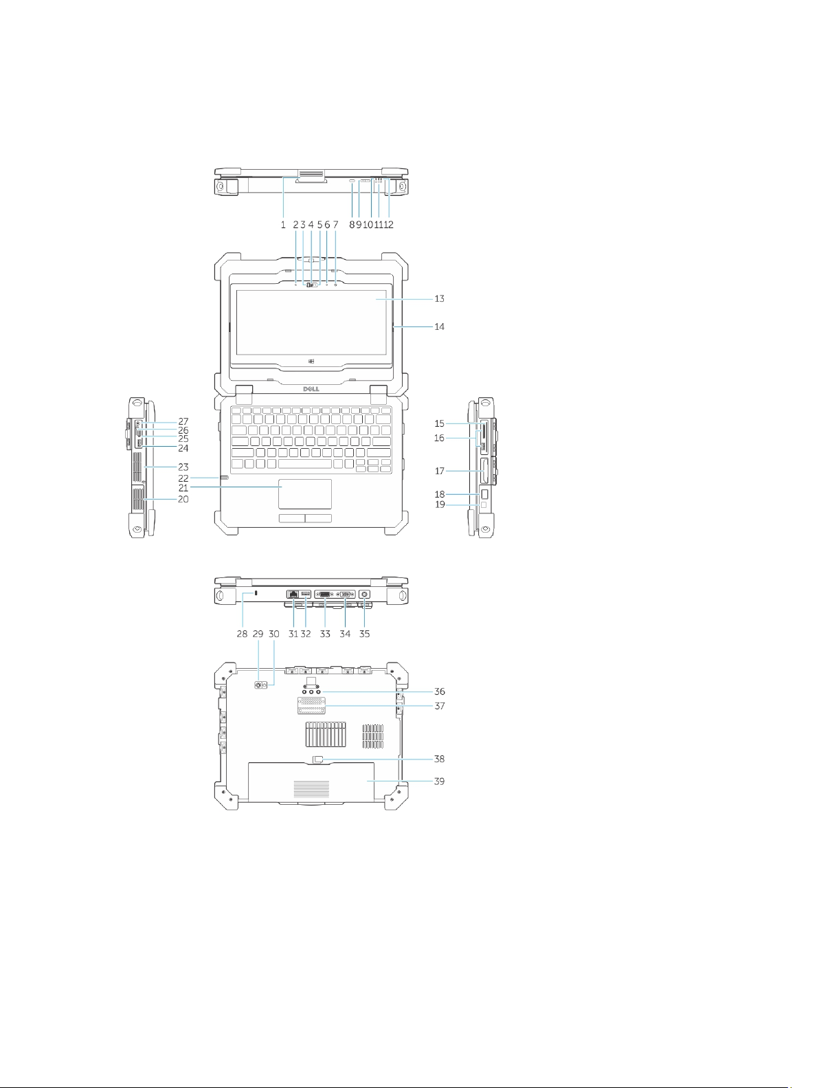
System overview
Figure 1. System overview
1. display latch 2. microphone
3. camera shutter (optional) 4. camera (optional)
5. camera status light (optional) 6. microphone
7. ambient light sensor 8. screen rotate button
9. volume button 10. power status lights
4
Page 6
11. hard drive activity light 12. battery status light
13. rotatable outdoor readable display/
touchscreen
15. secure card reader 16. USB 3.0 port and memory card reader/PC
17. hard disk 18. finger print reader
19. power button 20. sealed thermal chamber
21. touchpad 22. stylus
23. sealed thermal chamber 24. USB 3.0 connector with PowerShare
25. HDMI port 26. SIM card reader
27. audio connector 28. security cable slot
29. back camera 30. camera flash
31. network port 32. USB 2.0 port
33. serial port 34. VGA port
35. power connector 36. radio frequency pass-through connectors
37. docking device connector 38. battery latch
39. battery
CAUTION: EXPLOSION HAZARD—External connections (power adapter port, HDMI port, USB
ports, RJ45 port, serial ports, audio port, Smart Card reader slot, SD card reader slot, Express
Card reader slot, PC card reader slot, SIM card slot) should not to be used in a hazardous location.
14. flip hinge
card reader/Express card reader (optional)
WARNING: Do not block, push objects into, or allow dust to accumulate in the air vents. Do not
store your Dell computer in a low-airflow environment, such as a closed briefcase, while it is
running. Restricting the airflow can damage the computer or cause a fire. The computer turns on
the fan when the computer gets hot. Fan noise is normal and does not indicate a problem with
the fan or the computer.
5
Page 7
Quick setup
WARNING: Before you begin any of the procedures in this section, read the safety information
that shipped with your computer. For additional best practices information, see Dell.com/
regulatory_compliance.
WARNING: The AC adapter works with electrical outlets worldwide. However, power connectors
and power strips vary among countries. Using an incompatible cable or improperly connecting
the cable to the power strip or electrical outlet may cause fire or equipment damage.
CAUTION: When you disconnect the AC adapter cable from the computer, grasp the connector,
not the cable itself, and pull firmly but gently to avoid damaging the cable. When you wrap the
AC adapter cable, ensure that you follow the angle of the connector on the AC adapter to avoid
damaging the cable.
NOTE: Some devices may not be included if you did not order them.
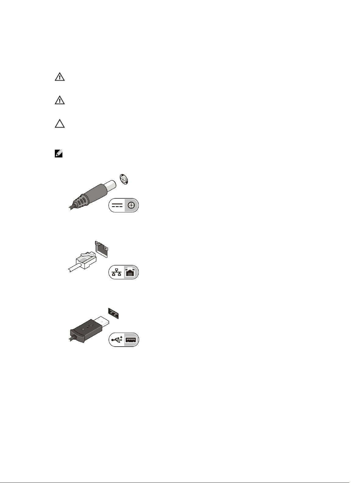
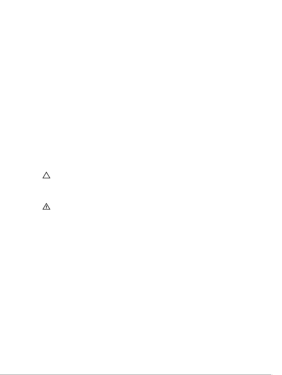
1. Connect the AC adapter to the AC adapter port on the computer and to the electrical outlet.
Figure 2. AC adapter
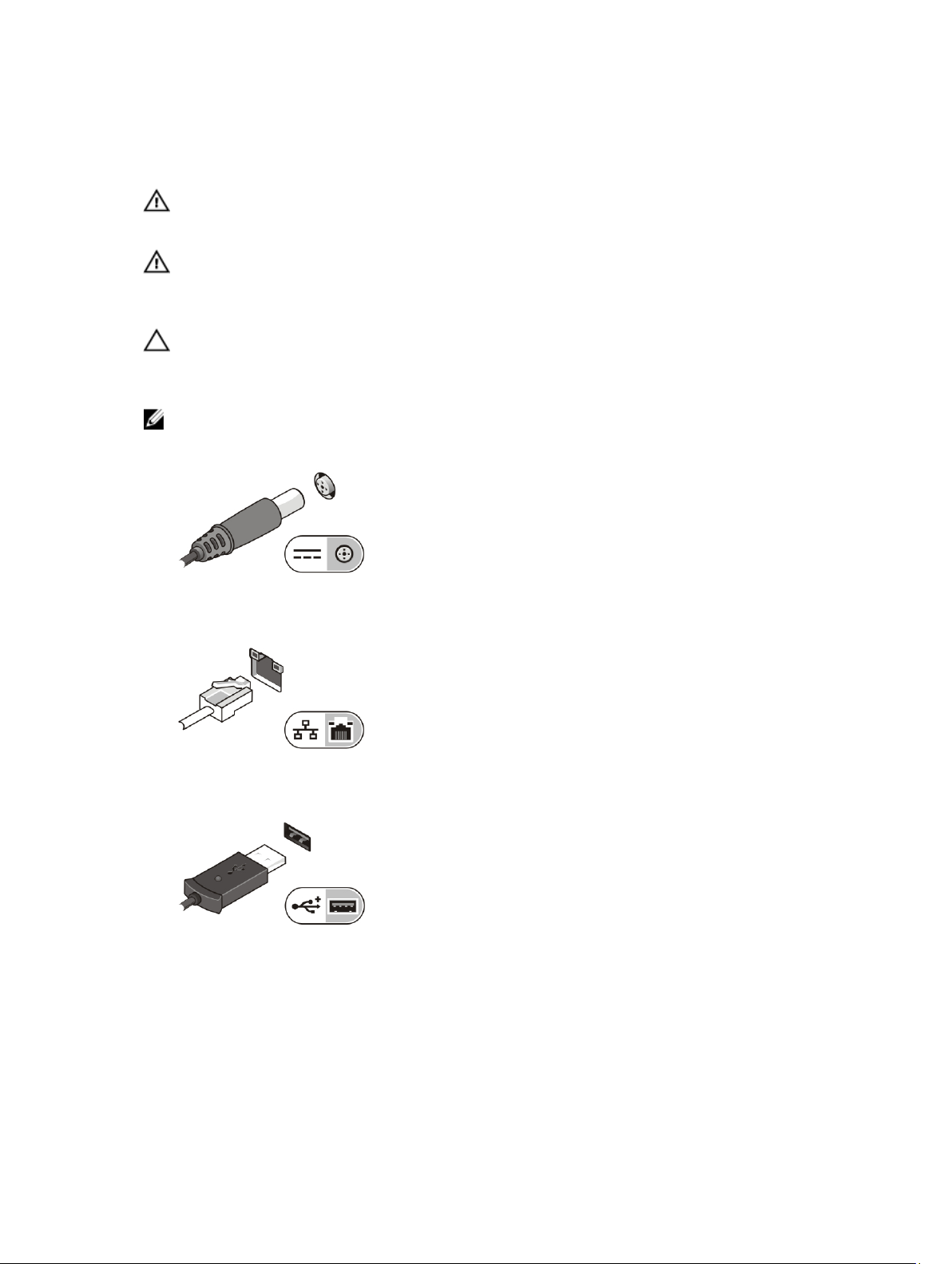
2. Connect the network cable (optional).
Figure 3. Network connector
3. Connect USB devices, such as a mouse or keyboard (optional).
Figure 4. USB connector
4. To turn on the computer, open the computer display and press the power button.
6
Page 8

Figure 5. Power button
NOTE: It is recommended that you turn on and shut down your computer at least once before you
install any cards or connect the computer to a docking device or other external device, such as a
printer.
7
Page 9
Removing and installing components
This section provides detailed information on how to remove or install the components from your
computer.
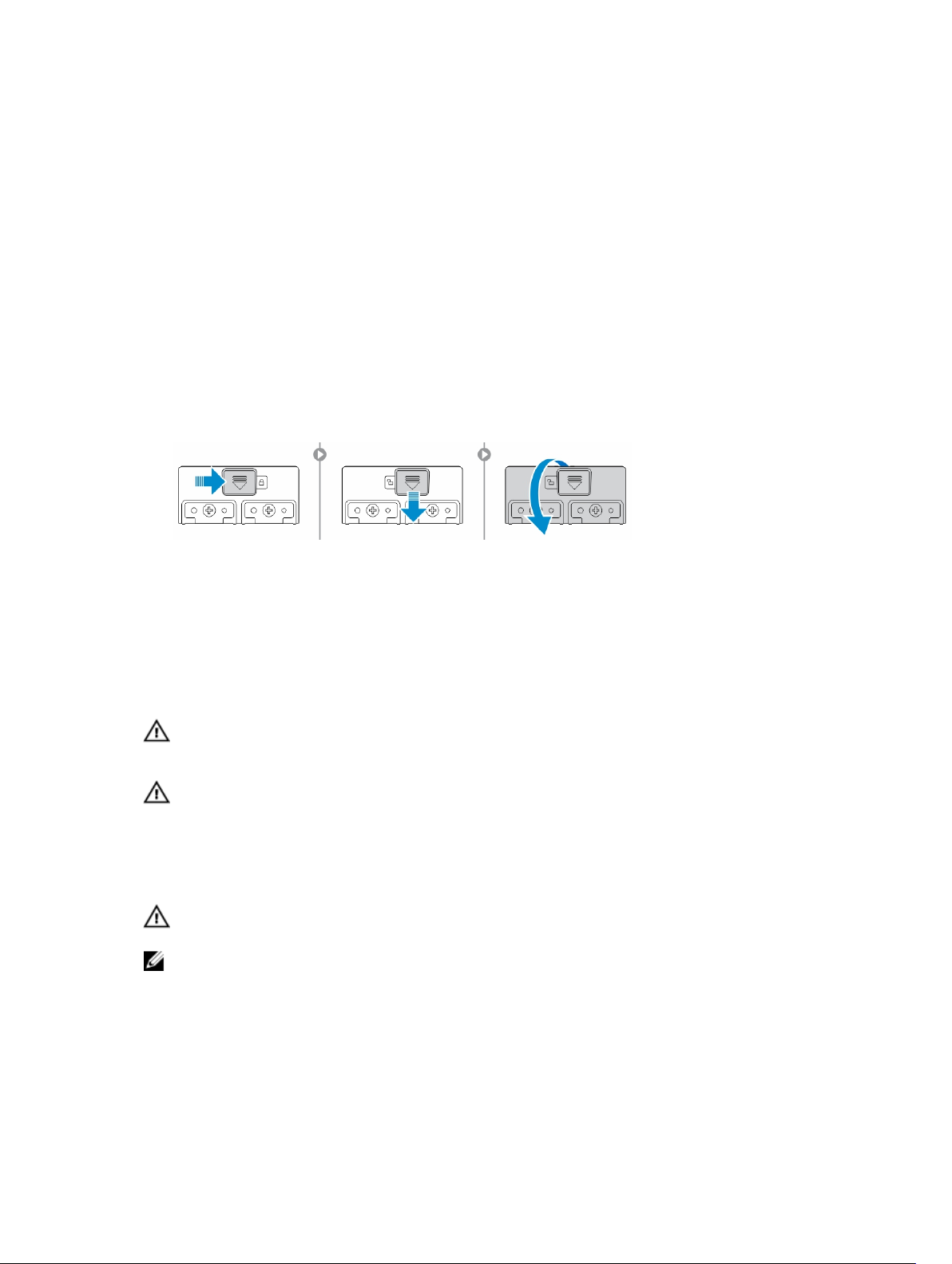
Opening the press latch doors
The computer includes six press latch doors:
• Three on the back of the computer
• Two on the right side of the computer
• One on the left side of the computer
1. Slide the latch until the unlock icon is visible.
2. Press the latch and open the press latch door in the downward direction.
Closing the press latch doors
1. Close the latch door back by pressing it toward the computer.
2. To lock the latch doors, slide the latch until the lock icon is visible.
Removing the battery
WARNING: Using an incompatible battery may increase the risk of fire or explosion. Replace the
battery only with a compatible battery purchased from Dell. The battery is designed to work with
your Dell computer. Do not use a battery from other computers with your computer.
WARNING: Before removing or replacing the battery:
1. Turn off the computer.
2. Disconnect the AC adapter from the electrical outlet and the computer.
3. Disconnect the modem from the wall connector and computer.
4. Remove any other external cables from the computer.
WARNING: To prevent ignition in a hazardous atmosphere, batteries must only be removed,
changed or charged in an area known to be non-hazardous.
NOTE: The battery cannot be installed or removed with the optional accessory handle installed. The
handle must be removed first (if present).
1. Unlock the battery release latch by pushing it upwards.
2. Slide the latch to the right to release the battery.
3. Remove the battery from the computer.
8
Page 10
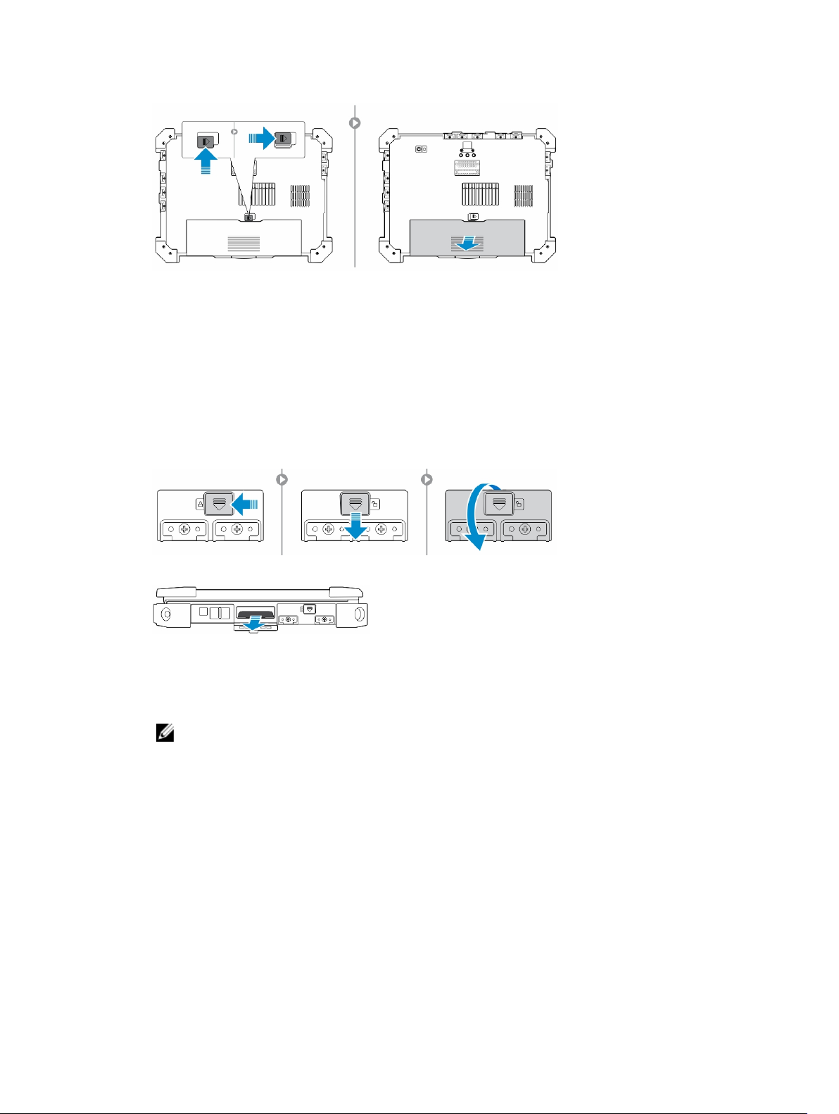
Installing the battery
1. Slide the battery into its slot.
2. Push the battery latch down to lock it.
Removing the hard drive
1. To open the hard drive latch door, push the latch button to the left (if locked).
2. Open the hard drive latch door by pushing the latch down.
3. Pull the hard drive outwards using the pull tab and remove it from the computer.
Installing the hard drive
1. Insert the hard drive into the hard drive slot until it clicks into place.
NOTE: Keep the hard drive pull tab clear of the doors before closing the hard drive latch door.
2. Close the hard drive latch door.
3. Slide the latch until the lock icon is visible.
9
Page 11
Working on your computer
This section provides information about the backlit keyboard, stealth mode, function keys and converting
your computer to notebook and tablet modes (if applicable).
Using the backlit keyboard
The Latitude rugged series comes equipped with a backlit keyboard that can be customized. The
following colors are enabled:
1. White
2. Red
3. Green
4. Blue
Alternatively, the system can be configured with two additional custom colors in the System Setup (BIOS).
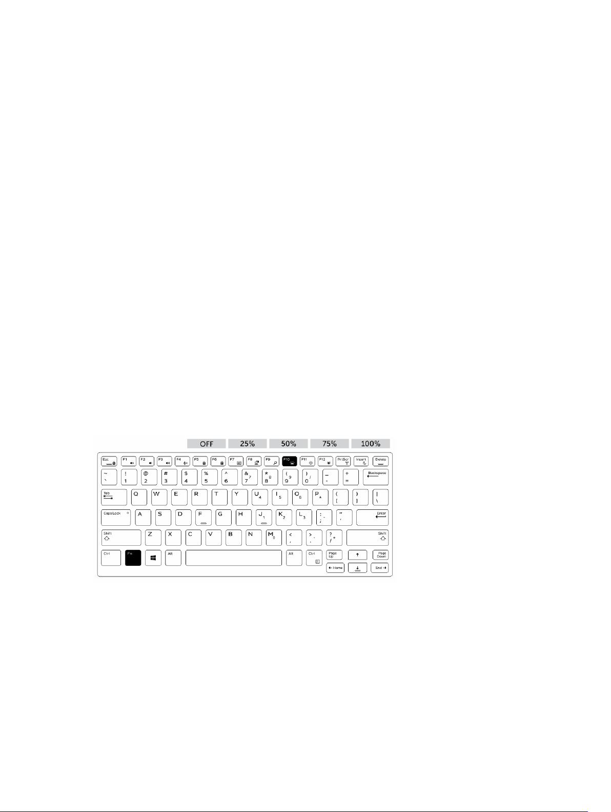
Turning the keyboard backlight on/off or adjusting brightness
To turn the backlight on/off or adjust the backlight brightness settings:
1. To initialize the keyboard backlight switch, press Fn+F10 (the Fn key is not needed if function key Fn
lock is enabled).
2. The first use of the preceding key combination turns on the backlight to its lowest setting.
3. Repeated pressing of the key combinations cycles the brightness settings through 25 percent,
50 percent, 75 percent and 100 percent.
4. Cycle through the key combination to either adjust the brightness or turn off the keyboard backlight.
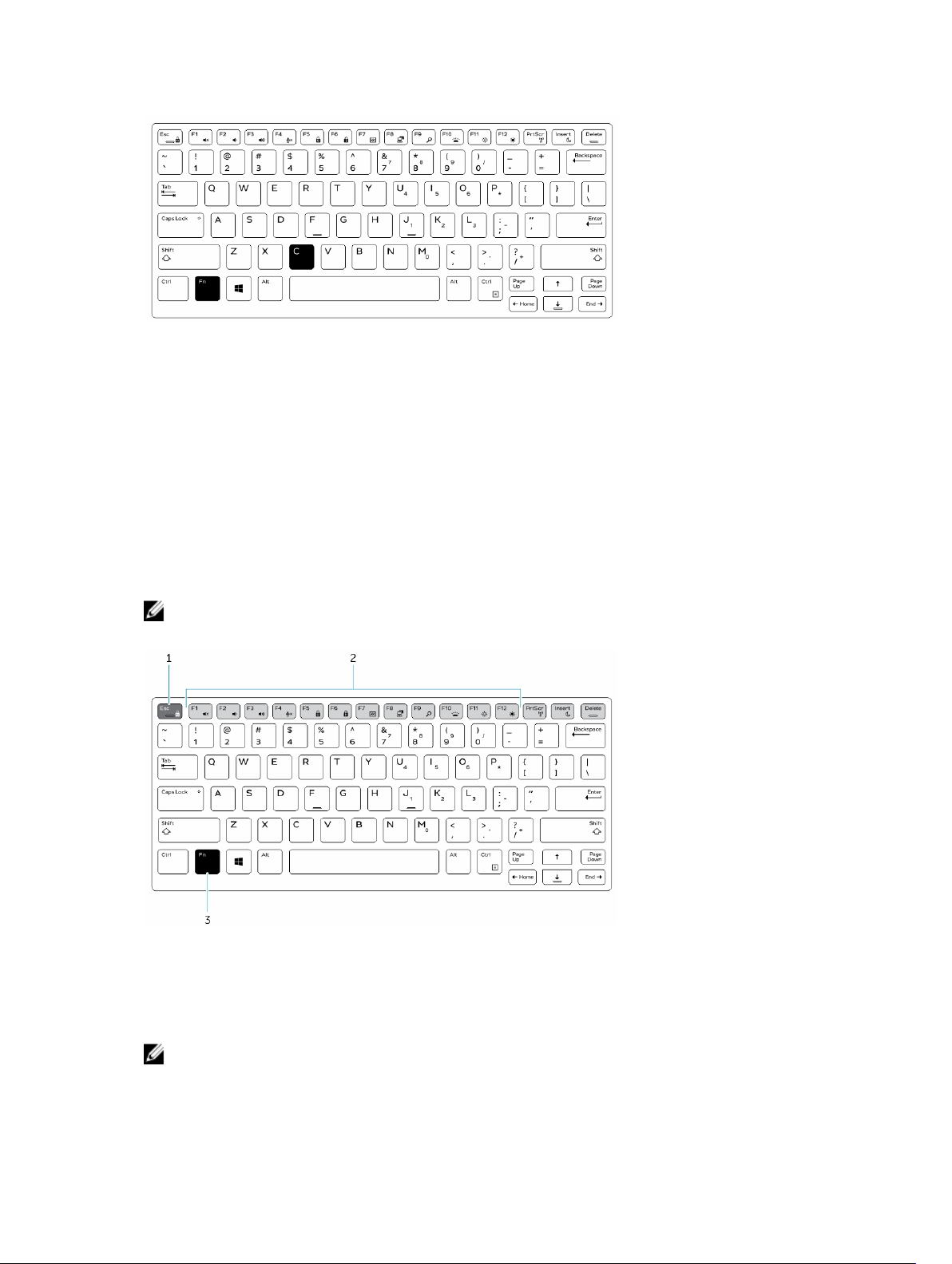
Changing the keyboard backlight color
To change the keyboard backlight color:
1. Press Fn+C keys to cycle through the available backlight colors.
2. White, Red, Green and Blue are active by default; up to two custom colors can be added to the cycle
in the System Setup (BIOS).
10
Page 12
Customizing the backlit keyboard in System Setup (BIOS)
1. Turn off the computer.
2. Turn on the computer and when the Dell logo appears, press the F2 key repeatedly to bring up the
System Setup menu.
3. Under System Configuration menu, select RGB Keyboard Backlight.
You can enable/disable the standard colors (White, Red, Green and Blue).
4. To set a custom RGB value, use the input boxes on the right side of the screen.
5. Click Apply changes and click Exit to close System Setup.
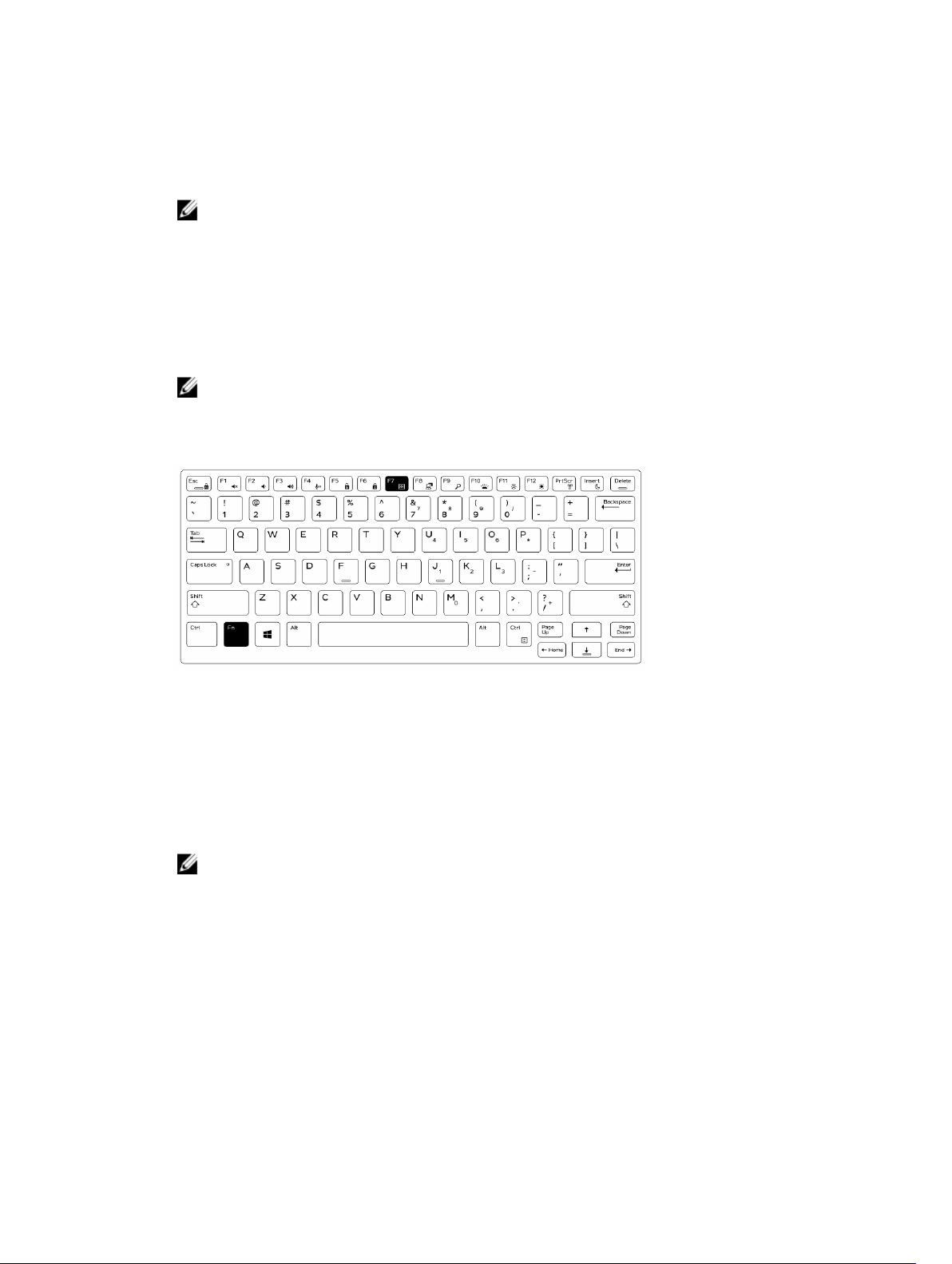
Function Fn key lock features
NOTE: The keyboard has Function key Fn lock capability. When activated, the secondary functions
on the top row of keys become default and will not require use of the Fn key.
Figure 6. Fn key callouts
1. Fn lock key
2. Affected Fn keys
3. Fn key
NOTE: Fn lock affects only the above keys (F1 to F12). Secondary functions will not require the Fn
key to be pressed while enabled.
11
Page 13
Enabling the Function (Fn) lock
1. Press the Fn+Esc keys.
NOTE: Other secondary function keys on the top row are not affected and requires the use of
the Fn key.
2. Press the Fn+Esc keys again to deactivate the function lock feature.
The function keys return to the default actions.
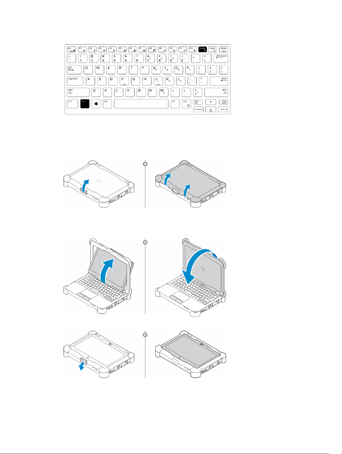
Turning stealth mode on/off
1. Press the Fn+F7 key combination (Fn key not needed if Fn lock is enabled) to turn on stealth mode.
NOTE: Stealth mode is a secondary function of the F7 key. The key can be used to perform
other functions on the computer when not used with the Fn key to enable stealth mode.
2. All the lights and sounds are turned off.
3. Press the Fn+F7 key combination again to turn off the stealth mode.
Disabling stealth mode in the system setup (BIOS)
1. Power off the computer.
2. Power on the computer and at the Dell logo, tap the F2 key repeatedly to bring up the System Setup
menu.
3. Expand and open the System Configuration menu.
4. Select Stealth Mode Control.
NOTE: Stealth mode is enabled by default.
5. To disable stealth mode uncheck the Enable Stealth Mode option.
6. Click Apply changes and click Exit.
Enabling and disabling the wireless (WiFi) feature
1. To enable wireless Networking, press Fn + PrtScr.
2. Press Fn + PrtScr again to disable wireless Networking.
12
Page 14
Converting between notebook and tablet modes
1. To undock the computer, press the display latch.
2. Open the display lid by lifting it upwards.
3. To change to tablet mode:
a. Gently push the display panel in the direction indicated to pop the display from the display frame.
b. Rotate the display by 180-degree until it clicks back into place.
4. Close the display lid.
13
Page 15

5. The computer is now converted for use in the tablet mode. Repeat the steps, flipping the display in
the opposite direction, to bring the computer back to notebook mode.
14
Page 16
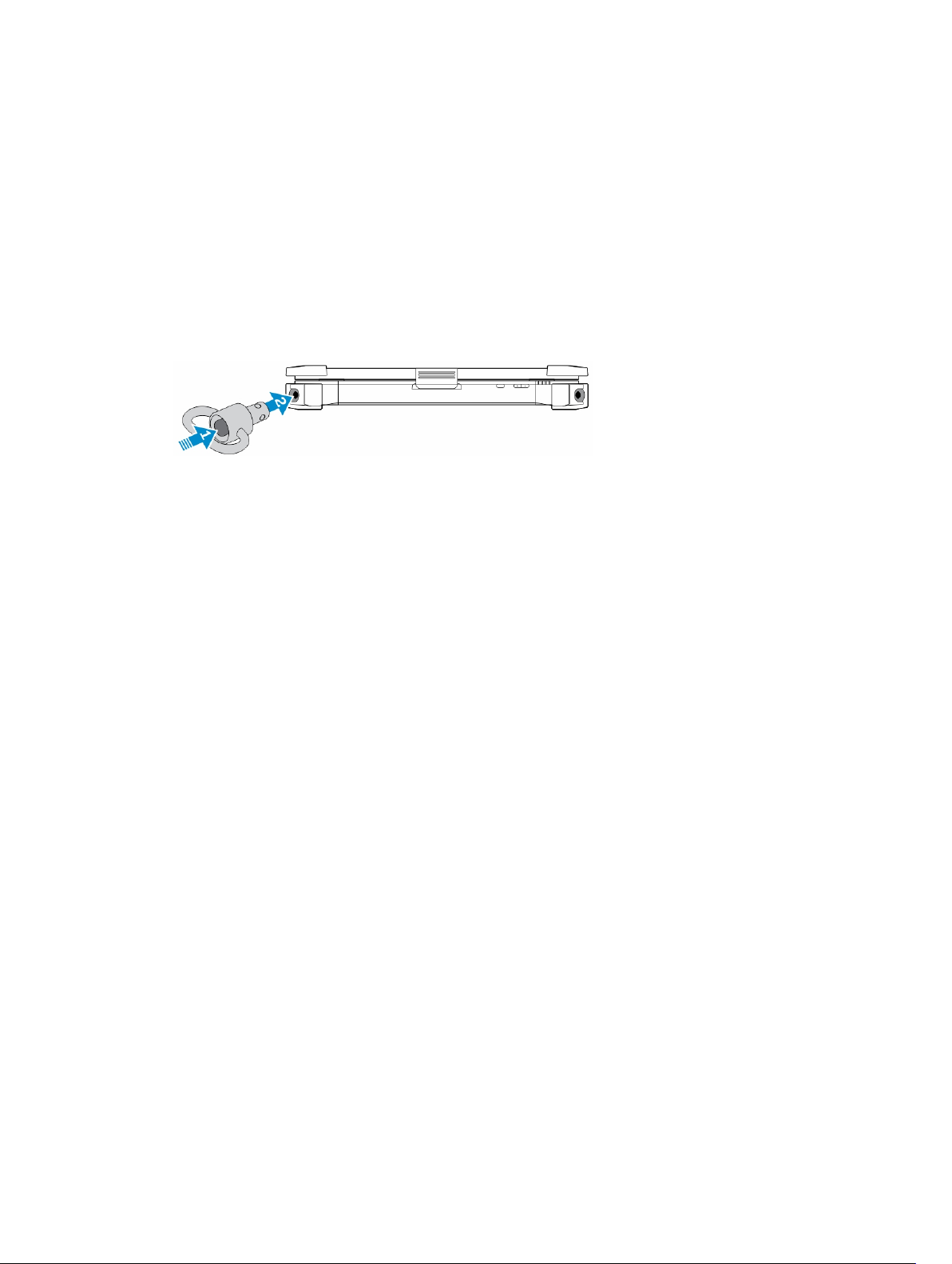
Quick Disconnect (QD) connector
Latitude fully rugged products come equipped with receptacles for QD (Quick Disconnect) connectors at
the corners. These receptacles allow the connection of optional accessories such as shoulder straps.
Installing the QD connector
1. Align the QD connector to the receptacle on the corner of the computer.
2. Press and hold the button on top of the QD connector.
3. Insert the QD connector into the receptacle, while holding the button pressed.
4. Release the button after the connector is seated in the receptacle to secure it.
Removing the QD connector
1. Press and hold the button on top of the QD connector.
2. Pull the connector out of the receptacle while holding the button pressed.
15
Page 17
Technical specifications
NOTE: Offerings may vary by region. For more information regarding the configuration of your
computer in:
• Windows 10, click or tap Start → Settings → System → About.
• Windows 8.1 and Windows 8, from the charms sidebar, click or tap Settings → Change PC
settings
• Windows 7, click Start , right-click My Computer, and then select Properties.
System information specifications
Feature Specification
DRAM bus width 64 bit
Flash EPROM SPI 128 Mbits
PCIe 3.0 bus 8.0 GHz
Processor specifications
. In the PC Settings window, select PC and devices → PC Info.
Feature Specification
Types Intel Core i3/i5/i7 series
L3 cache up to 4 MB
External bus
frequency
2133 MHz
Memory specifications
Feature Specification
Memory
connector
Memory capacity 4 GB, 8 GB, and 16 GB
Memory type DDR4 SDRAM
Speed 2133 MHz
Minimum memory 4 GB
Maximum memory 32 GB
Two SODIMM slots
16
Page 18

Audio specifications
Feature Specification
Type four channel high definition audio
Controller HDA Codec - ALC3235
Stereo conversion 24 bit (analog-to-digital and digital-to-analog)
Interface (internal) HD audio
Interface (external) microphone in/stereo headphones/external speakers connector
Speakers one mono speaker
Internal speaker
amplifier
Volume controls Volume up/Volume down buttons
CAUTION: Adjustment of volume control, as well as the equalizer in the operating system and/or
equalizer software, to other settings than the center position may increase the earphones and/or
headphones output and cause hearing damage or loss.
2 W (RMS)
Video specifications
Feature Specification
Type integrated on system board
Controller (UMA)
— Intel core
i3/i5/i7
Intel HD Graphics 520
Communication specifications
Feature Specification
Network adapter 10/100/1000 Mb/s Ethernet (RJ-45)
Wireless
• WLAN with Bluetooth 4.1 enabled
• WWAN
Port and connector specifications
Feature Specification
Audio one microphone/stereo headphone/speakers connector
Video
• one 19-pin HDMI port
17
Page 19

Feature Specification
• one 15-pin VGA port
Network adapter one RJ45 connector
Serial port one DB9 pin serial port
Docking port one
USB ports
SIM card slot one micro-SIM slot with security feature
• one 4-pin USB 2.0-compliant port
• one 9-pin USB 3.0-compliant port with PowerShare
• one USB 3.0 port and memory card reader/PC card reader/ExpressCard reader
(optional)
Display specifications
Feature Specification
Type WLED display
Size 11.6 inches
Height 190.00 mm (7.48 inches)
Width 323.5 mm (12.59 inches)
Diagonal 375.2 mm (14.77 inches)
Active area (X/Y) 309.4 mm x 173.95 mm
Maximum
resolution
Refresh rate 60 Hz
1366 x 768 pixels
Operating angle 0° (closed) to 180°
Maximum viewing
angles (horizontal)
Maximum viewing
angles (vertical)
Pixel pitch 0.1875 mm
+/- 70° minimum for HD
+/- 70° minimum for HD
Keyboard specifications
Feature Specification
Number of keys
18
• 83 keys: US English, Thai, French-Canadian, Korean, Russian, Hebrew, EnglishInternational
Page 20

Feature Specification
• 84 keys: UK English, French Canadian Quebec, German, French, Spanish (Latin
America), Nordic, Arabic, Canada Bilingual
• 85 keys: Brazilian Portuguese
• 87 keys: Japanese
Layout QWERTY/AZERTY/Kanji
Touchpad specifications
Feature Specification
Active Area:
X-axis 99.50 mm
Y-axis 53.00 mm
Battery specifications
Feature Specification
Type
Depth
Height
Width
Weight
Voltage 14.8 V DC
Life span 300 discharge per charge cycles
Temperature range
Operating
Nonoperating –51°C to 71°C (–60°F to 160°F)
4-cell smart lithium ion
72.6 mm (2.85 inches)
16.6 mm (0.65 inches)
215 mm (8.46 inches)
318 g (0.70 lb)
• Charging: 0°C to 60°C (32°F to 140°F)
• Discharging: 0°C to 70°C (32°F to 158°F)
NOTE: The battery pack is capable of safely withstanding the above storage
temperatures with 100% charge.
NOTE: The battery pack is also capable of withstanding storage temperatures
from –20°C to +60°C with no degradation in its performance.
19
Page 21

Feature Specification
Coin cell battery 3 V CR2032 lithium coin cell
Adapter specifications
Feature Specification
Type 65 W
Input voltage 100–240 V AC
Input current
(maximum)
Input frequency 50–60 Hz
Output current
Rated output
voltage
Temperature range
(operating)
Temperature range
(nonoperating)
1.7 A
3.34 A
19.5 V DC
0°C to 40°C (32°F to 104°F)
–40°C to 70°C (–40°F to 158°F)
Physical dimension specifications
Feature Specification
Height 39 mm (1.54 inches)
Width 219 mm (8.62 inches)
Length 311 mm (12.24 inches)
Weight (minimum
config)
6.0 lbs (2.72 kg)
Environmental specifications
Feature Specifications
Temperature —
operating
Temperature —
storage
Relative humidity
(maximum) —
operating
20
–29°C to 63°C (–20°F to 145°F)
–51°C to 71°C (–60°F to 160°F)
10% to 90% (noncondensing)
Page 22

Feature Specifications
Relative humidity
(maximum) —
storage
Altitude
(maximum) —
operating
Altitude
(maximum) —
nonoperating
Airborne
contaminant level
0% to 95% (noncondensing)
–15.24 m to 4572 m (–50 ft to 15,000 ft)
–15.24 m to 9144 m (–50 ft to 30,000 ft)
G1 as defined by ISA-71.04–1985
21
Page 23

Contacting Dell
NOTE: If you do not have an active Internet connection, you can find contact information on your
purchase invoice, packing slip, bill, or Dell product catalog.
Dell provides several online and telephone-based support and service options. Availability varies by
country and product, and some services may not be available in your area. To contact Dell for sales,
technical support, or customer service issues:
1. Go to Dell.com/support.
2. Select your support category.
3. Verify your country or region in the Choose a Country/Region drop-down list at the bottom of the
page.
4. Select the appropriate service or support link based on your need.
22
Page 24

Dell Latitude 12 Rugged Extreme – 7214
Guide de mise en route
Modèle réglementaire: P18T
Type réglementaire: P18T002
Page 25
Remarques, précautions et
avertissements
REMARQUE : Une REMARQUE indique des informations importantes qui peuvent vous aider à mieux
utiliser votre ordinateur.
PRÉCAUTION : Une PRÉCAUTION indique un risque d'endommagement du matériel ou de perte
de données et vous indique comment éviter le problème.
AVERTISSEMENT : Un AVERTISSEMENT indique un risque d'endommagement du matériel, de
blessures corporelles ou même de mort.
© 2016 Dell Inc. Tous droits réservés. Ce produit est protégé par les lois sur les droits d'auteur et la propriété
intellectuelle des États-Unis et des autres pays. Dell et le logo Dell sont des marques de Dell Inc. aux États-Unis et/ou
dans d'autres juridictions. Toutes les autres marques et tous les noms de produits mentionnés dans ce document
peuvent être des marques de leurs sociétés respectives.
2016 - 06
Rév. A01
Page 26

Trouver des informations et des ressources supplémentaires
Consultez les documents réglementaires et de sécurité livrés avec votre ordinateur et la page Regulatory
Compliance (Conformité à la réglementation) à l'adresse Dell.com/regulatory_compliance pour plus
d'informations sur :
• Les meilleures pratiques en matière de sécurité
• La certification réglementaire
• L'ergonomie
Consultez le site Dell.com pour des informations plus détaillées sur :
• La garantie
• Les conditions générales (États-Unis seulement),
• Le contrat de licence pour utilisateur final
Des informations supplémentaires sur nos produits sont disponibles sur Dell.com/support/manuals.
3
Page 27
Présentation du système
Figure 1. Présentation du système
1. loquet de l'écran 2. microphone
3. Obturateur d'appareil photo (en option) 4. caméra (en option)
5. voyant d'état de la caméra (en option) 6. microphone
7. Capteur de lumière ambiante 8. bouton de rotation de l'écran
9. bouton de volume 10. Voyants d’état de l’alimentation
4
Page 28
11. voyant d'activité du disque dur 12. voyant d'état de la batterie
13. Affichage/écran tactile rotatif utilisable à
l'extérieur
15. Lecteur de carte sûr 16. Port USB 3.0 et lecteur de carte mémoire/
17. Disque dur 18. lecteur d'empreintes digitales
19. bouton d’alimentation 20. chambre thermique hermétique
21. pavé tactile 22. stylet
23. chambre thermique hermétique 24. Connecteur USB 3.0 avec PowerShare
25. Port HDMI 26. Lecteur de carte SIM
27. connecteur audio 28. fente pour câble de sécurité
29. Caméra arrière 30. Flash de caméra
31. Port réseau 32. Port USB 2.0
33. port série 34. port VGA
35. connecteur d’alimentation 36. connecteurs d’intercommunication de
37. connecteur de la station d’accueil 38. loquet de la batterie
39. batterie
PRÉCAUTION : RISQUE D'EXPLOSION — les connexions externes (port d'adaptateur
d'alimentation, port HDMI, ports USB, port RJ-45, les ports série, port audio, emplacement pour
lecteur de carte à puce, logement du lecteur de carte SD, logement du lecteur de carte Express,
logement pour lecteur de carte PC, logement de carte SIM) ne doivent pas être utilisées dans une
zone dangereuse.
14. Charnière de basculement
lecteur de carte PC/lecteur de carte Express
(en option)
fréquence radio
AVERTISSEMENT : Ne bloquez pas les entrées d'air de l'ordinateur et n'insérez pas d'objets
dedans ; évitez également toute accumulation de poussière. Ne placez pas l'ordinateur Dell dans
un environnement peu aéré, tel qu'une mallette fermée, lorsque celui-ci fonctionne. Ceci risque
d'endommager l'ordinateur ou de provoquer un incendie Le ventilateur se met en marche lorsque
l'ordinateur commence à chauffer. Il se peut que le ventilateur fasse du bruit ; cela est tout à fait
normal et ne signifie en aucun cas que le ventilateur ou l'ordinateur est défectueux.
5
Page 29
Installation rapide
AVERTISSEMENT : Avant de commencer à appliquer toute procédure expliquée dans cette
section, prenez connaissance des consignes de sécurité fournies avec votre ordinateur. Pour en
savoir plus sur les bonnes pratiques, consultez le site
AVERTISSEMENT : L’adaptateur secteur fonctionne avec les prises électriques du monde entier.
Mais les connecteurs et les barrettes d’alimentation varient d’un pays à l’autre. L’utilisation d’un
câble non compatible ou le branchement incorrect du câble sur la multiprise ou sur la prise
électrique risquent de provoquer un incendie ou d’endommager l’équipement.
PRÉCAUTION : Lorsque vous déconnectez de l’ordinateur le câble de l’adaptateur secteur,
saisissez le connecteur et non le câble lui-même, puis tirez fermement mais avec précaution pour
éviter d’endommager le câble. Pour enrouler le câble de l’adaptateur secteur, vérifiez que vous
suivez l’angle du connecteur de l’adaptateur pour éviter d’endommager le câble.
REMARQUE : Les périphériques mentionnés ne sont inclus que si vous les avez commandés.
1. Branchez le connecteur de l’adaptateur secteur à l’ordinateur et à la prise électrique.
Figure 2. Adaptateur CA
Dell.com/regulatory_compliance .
2. Branchez le câble réseau (en option).
Figure 3. Connecteur réseau
3. Connectez des périphériques USB, une souris ou un clavier, par exemple (facultatif).
Figure 4. Connecteur USB
4. Pour allumer l'ordinateur, relevez l'écran et appuyez sur le bouton d'alimentation.
6
Page 30

Figure 5. Bouton d'alimentation
REMARQUE : Il est recommandé d’allumer et d’éteindre l’ordinateur au moins une fois avant
d’installer des cartes ou de connecter l’ordinateur à une station d’accueil ou un autre périphérique
externe tel qu’une imprimante.
7
Page 31

Retrait et installation de composants
Cette section fournit des informations détaillées sur le retrait ou l'installation des composants de
l'ordinateur.
Ouverture des panneaux à verrouillage par pression
L'ordinateur comprend six panneaux de verrouillage :
• Trois situés à l'arrière de l'ordinateur
• Deux sur le côté droit de l'ordinateur
• Un sur le côté gauche de l'ordinateur
1. Faites glisser le loquet jusqu'à ce que l'icône de déverrouillage soit visible.
2. Appuyez sur le loquet et faites glisser le panneau de verrouillage vers le bas.
Fermeture des panneaux à verrouillage par pression
1. Refermez le panneau de verrouillage en appuyant dans la direction de l'ordinateur.
2. Pour verrouiller les panneaux à pression, faites glisser le loquet jusqu'à ce que l'icône de verrouillage
soit visible.
Retrait de la batterie
AVERTISSEMENT : L’utilisation d’une batterie non compatible peut accroître le risque d’incendie
ou d’explosion. Remplacez la batterie uniquement par une batterie compatible achetée auprès de
Dell. La batterie est conçue pour fonctionner avec votre ordinateur Dell. N’utilisez pas une
batterie provenant d’autres ordinateurs dans le votre.
AVERTISSEMENT : Avant de retirer ou de remplacer la batterie :
1. Éteignez l'ordinateur.
2. Débranchez l'adaptateur CA de la prise secteur et de l'ordinateur.
3. Débranchez le modem de la prise murale et de l'ordinateur.
4. Retirez les autres câbles externes de l'ordinateur.
AVERTISSEMENT : Pour prévenir les incendies en atmosphère dangereuse, les batteries doivent
être enlevées, changées ou chargées uniquement en zone non dangereuse.
REMARQUE : La batterie ne peut pas être installée ou retirée avec la poignée d’accessoires en
option installée. La poignée doit être déposé d’abord (le cas échéant).
1. Déverrouillez le loquet de verrouillage de la batterie en le poussant vers le haut.
2. Faites glisser le loquet vers la droite pour libérer la batterie.
8
Page 32

3. Retirez la batterie de l’ordinateur.
Installation de la batterie
1. Glissez la batterie dans son logement.
2. Poussez le loquet de la batterie vers le bas pour le verrouiller.
Retrait du disque dur
1. Pour ouvrir le loquet du volet de disque dur, poussez le bouton du loquet vers la gauche (s’il est
verrouillé).
2. Ouvrez le loquet du panneau de verrouillage du disque dur en le poussant vers le bas.
3. Tirez le disque dur vers l’extérieur à l’aide de la languette de traction et retirez-le de l’ordinateur.
Installation du disque dur
1. Insérez le disque dur dans son emplacement jusqu’à entendre un clic.
REMARQUE : Veillez à ne pas faire toucher les panneaux avec le panier du disque dur avant de
refermer la porte de l'emplacement pour disque dur.
2. Fermez le loquet de la porte de l'emplacement pour disque dur.
3. Faites glisser le loquet jusqu'à ce que l'icône de verrouillage soit visible.
9
Page 33

Intervention à l’intérieur de votre ordinateur
Cette section fournit des informations sur le clavier rétro-éclairé, le mode furtif, les touches de fonction
et la conversion de votre ordinateur aux modes ordinateur portable et tablette (le cas échéant).
Utilisation du clavier rétro-éclairé
La série résistante Latitude est équipée d’un clavier rétro-éclairé personnalisable. Les couleurs suivantes
sont possibles :
1. Blanc
2. Rouge
3. Vert
4. Bleu
De plus, le système peut être configuré avec deux couleurs personnalisées supplémentaires dans le
programme de configuration du système (BIOS).
Activation et désactivation du rétro-éclairage du clavier ou réglage de la
luminosité
Pour activer/éteindre le rétro-éclairage ou régler la luminosité du clavier :
1. Pour initialiser le bouton d'activation du rétro-éclairage du clavier, appuyez sur Fn+F10 (il n'est pas
nécessaire d'enfoncer la touche Fn si le verrouillage de celle-ci est actif).
2. La première utilisation de la combinaison de touches ci-dessus allume le rétro-éclairage à son
réglage minimum.
3. Appuyez à plusieurs reprises sur cette combinaison de touches pour basculer entre les différents
niveaux de luminosité : 25 %, 50 %, 75 % et 100 %.
4. Utilisez cette combinaison de touches pour basculer entre les différents réglages de luminosité ou
éteindre le rétro-éclairage du clavier.
Modification de la couleur de rétro-éclairage du clavier
Pour modifier la couleur de rétroéclairage du clavier :
10
Page 34

1. Appuyez de nouveau sur les touches « Fn+C » pour faire défiler les couleurs disponibles.
2. Blanc, rouge, vert et bleu sont actives par défaut ; jusqu’à deux couleurs personnalisées peut être
ajoutée au cycle dans le programme de configuration du système (BIOS).
Personnalisation du clavier rétro-éclairé dans le programme de
configuration du système (BIOS)
1. Éteignez l'ordinateur.
2. Allumez l’ordinateur et quand le logo Dell s'affiche, appuyez sur la touche « F2 » à plusieurs reprises
pour afficher le menu de configuration du système.
3. Dans le menu Configuration du système, sélectionnez Rétro-éclairage RVB du clavier.
Vous pouvez activer/désactiver les couleurs standard (blanc, rouge, vert et bleu).
4. Pour définir une valeur RVB personnalisée, utilisez les champs de saisie situés sur la droite de l’écran.
5. Cliquez sur Appliquer les modifications puis sur Quitter pour fermer la configuration du système.
Caractéristiques du verrouillage de la touche de Fonction « Fn »
REMARQUE : Le clavier a la capacité de verrouiller la touche Fonction « Fn ». Une fois activée, les
fonctions secondaires des touches de la ligne supérieure deviennent les fonctions par défaut et ne
nécessitent pas l’utilisation de la touche « Fn ».
Figure 6. Fonctions des touches compatibles avec la touche « Fn »
11
Page 35

1. Touche de verrouillage « Fn »
2. Touches « Fn » affectées
3. Touche « Fn »
REMARQUE : Le verrouillage de la touche « Fn » affecte uniquement les touches supérieures (F1 à
F12). Les fonctions secondaires ne nécessitent pas d'appuyer sur la touche « Fn » lorsque le
verrouillage est actif.
Activation du verrouillage de la touche Fonction (Fn)
1. Appuyez sur les touches « Fn+Échap ».
REMARQUE : Les autres touches de fonctions secondaires de la ligne supérieure ne sont pas
affectées et nécessitent l’utilisation de la touche « Fn ».
2. Appuyez encore sur les touches « Fn +Échap » pour désactiver le verrouillage de la touche Fonction.
Les actions par défaut des touches de fonction sont rétablies.
Activation/désactivation du mode furtif
1. Appuyez sur la combinaison de touches « Fn+F7 » (touche Fn inutile si le verrouillage de la touche Fn
est actif) pour activer le mode furtif.
REMARQUE : Le mode furtif est une fonction secondaire de la touche « F7 ». La touche peut
servir à d’autres fonctions de l’ordinateur lorsqu'elle n’est pas utilisée en conjonction de la
touche « Fn » pour activer le mode furtif.
2. Tous les voyants et les sons sont éteints.
3. Appuyez à nouveau sur la combinaison de touches « Fn+F7 » pour désactiver le mode furtif.
Désactivation du mode furtif dans la configuration du système (BIOS)
1. Mettez l'ordinateur hors tension.
2. Allumez l’ordinateur et quand le logo Dell s'affiche, appuyez sur la touche « F2 » à plusieurs reprises
pour afficher le menu de configuration du système.
3. Développez et ouvrez le menu de configuration du système .
4. Sélectionnez le mode de commande furtif.
REMARQUE : Le mode furtif est activé par défaut.
12
Page 36

5. Pour désactiver mode furtif, décochez l'option Activation du mode furtif.
6. Cliquez sur Appliquer les modifications puis cliquez sur Quitter.
Activation et désactivation de la fonction sans-fil (WiFi)
1. Pour activer les fonctions de réseau sans-fil, appuyez sur « Fn+PrtScr ».
2. Appuyez encore sur les touches « Fn+PrtScr » pour désactiver le réseau sans-fil.
Conversion entre les modes ordinateur portable et tablette
1. Pour détacher l’ordinateur, appuyez sur le loquet de l’écran.
2. Ouvrez le capot de l'écran en le soulevant vers le haut.
3. Pour passer en mode tablette :
a. Poussez doucement le panneau d’écran dans le sens indiqué pour le libérer de son cadre.
b. Faites pivoter l’écran de 180 degrés jusqu’à ce qu’il s’encliquette.
4. Fermez le capot de l'écran.
13
Page 37

5. L’ordinateur est à présent converti pour l'utiliser en mode tablette. Répétez les étapes, en rabattant
l'écran dans l'autre sens, pour remettre l'ordinateur en mode portable.
14
Page 38

Déconnexion rapide (connecteur QD)
Les produits résistants Latitude sont équipés de logements pour connecteurs QD (déconnexion rapide)
sur les coins. Ces connecteurs permettent de raccorder des accessoires en option tels que bandoulière
par exemple.
Installation du connecteur QD
1. Alignez le connecteur QD avec le réceptacle au coin de l’ordinateur.
2. Maintenez le bouton enfoncé sur le dessus du connecteur QD.
3. Insérez le connecteur QD dans l'emplacement en maintenant le bouton enfoncé.
4. Relâchez le bouton une fois le connecteur enclenché dans le réceptacle pour le fixer.
Retrait du connecteur QD
1. Maintenez le bouton enfoncé sur le dessus du connecteur QD.
2. Sortez le connecteur de son réceptacle en maintenant le bouton enfoncé.
15
Page 39

Spécifications techniques
REMARQUE : Les offres peuvent varier en fonction de la région. Plus d’informations sur la
configuration de votre ordinateur dans :
• Windows 10, cliquez ou appuyez sur Démarrer → Paramètres → système → sur.
• Pour Windows 8.1 et Windows 8, depuis la barre latérale, cliquez ou appuyez sur Paramètres →
Modifier les paramètres du PC. Sur la fenêtre des Paramètres PC, sélectionnez PC et
périphériques → Infos PC.
• Windows 7, cliquez sur Démarrer , cliquez avec le bouton droit de la souris sur Mon
ordinateur, puis sélectionnez Propriétés.
Spécifications des Informations système
Fonction Spécification
Largeur de bus
DRAM
Flash EPROM SPI 128 Mbits
Bus PCIe 3.0 8,0 GHz
64 bits
Spécifications du processeur
Fonction Spécification
Types Intel Core i3/i5/i7 series
Mémoire cache L3 jusqu'à 4 Mo
Fréquence du bus
externe
2133 MHz
Spécifications de la mémoire
Fonction Spécification
Connecteur
mémoire
Capacité mémoire 4 Go, 8 Go et 16 Go
Deux logements SO-DIMM
Type de mémoire SDRAM DDR4
Vitesse 2133 MHz
Mémoire minimale 4 Go
Mémoire maximale 32 Go
16
Page 40

Spécifications audio
Fonction Spécification
Type Audio haute définition à quatre canaux
Contrôleur Codec HDA - ALC 3235
Conversion stéréo 24 bits (analogique-numérique et numérique-analogique)
Interface (interne) Audio HD
Interface (externe) connecteur entrée microphone/casque stéréo/haut-parleurs externes
Haut-parleurs Un haut-parleur mono
Amplificateur de
haut-parleurs
intégré
Réglages du
volume
PRÉCAUTION : Le réglage de la commande de volume, ainsi que de l’égaliseur dans le système
d’exploitation et/ou le logiciel d’égaliseur, sur d’autres paramètres que sa position centrale peut
augmenter la puissance de sortie casque et/ou des écouteurs et provoquer des troubles ou la
perte de l’audition.
2 W (RMS)
Boutons d’augmentation et de diminution du volume
Spécifications vidéo
Fonction Spécification
Type intégrée sur la carte système
Contrôleur (UMA)
- Intel Core i3/i5/i7
Intel HD Graphics 520
Spécifications de communication
Fonction Spécification
Carte réseau Ethernet 10/100/1000 Mb/s (RJ-45)
Sans fil
• Réseau local sans-fil avec technologie Bluetooth 4.1 activé
• WWAN
Caractéristiques des ports et connecteurs
Fonction Caractéristiques
Audio un connecteur de microphone/casque stéréo/haut-parleurs
17
Page 41

Fonction Caractéristiques
Vidéo
Carte réseau un connecteur RJ45
Port série un port série DB9 broches
Port d’accueil un
Ports USB
logement pour
carte SIM
• un port HDMI à 19 broches
• un port VGA à 15 broches
• Un port à 4 broches, compatible USB 2.0
• un connecteur à 9 broches compatible USB 3.0 avec PowerShare
• Un port USB 3.0 et lecteur de cartes mémoires/lecteur de cartes PC/lecteur de
cartes Express (en option)
Un logement micro-SIM avec fonction de sécurité
Spécifications de l’écran
Fonction Spécification
Type écran WLED
Size (Taille) 11,6 pouces
Hauteur 190 mm (7,48 pouces)
Largeur 323,5 mm (12,59 pouces)
Diagonale 375,2 mm (14,77 pouces)
Zone active (X/Y) 309,4 mm × 173,95 mm
Résolution
maximale
Fréquence de
rafraîchissement
Angle de
fonctionnement
Angles de vue
maximaux
(horizontal)
Angles de vue
maximaux
(vertical)
Pas de pixel 0,1875 mm
1366 x 768 pixels
60 Hz
De 0° (fermé) à 180°
+/- 70° minimum pour HD
+/- 70° minimum pour HD
18
Page 42

Spécifications du clavier
Fonction Spécification
Nombre de
touches
Disposition QWERTY/AZERTY/Kanji
• 83 touches : anglais américain, thaï, français canadien, coréen, russe, hébreu,
anglais international
• 84 touches : anglais britannique, français canadien (Québec), allemand,
français, espagnol (Amérique latine), pays nordiques, arabe, canadien bilingue
• 85 touches : portugais (Brésil)
• 87 touches : japonais
Spécifications du pavé tactile
Fonction Spécification
Zone active :
Axe des X 99,50 mm
Axe des Y 53,00 mm
Spécifications de la batterie
Fonction Spécification
Type
Batterie intelligente au lithium-ion 4 cellules
Profondeur
Hauteur
Largeur
Poids
Tension 14,8 VCC
Durée de vie 300 cycles de décharge/charge
Plage de
températures
En
fonctionnement
72,6 mm (2,85 pouces)
16,6 mm (0,65 pouce)
215 mm (8,46 pouces)
318 g (0,70 livre)
• Chargement : de 0 °C à 60 °C (de 32 °F à 140 °F)
19
Page 43

Fonction Spécification
• Déchargement : 0 °C à 70 °C (de 32 °F à 158 °F)
Hors
fonctionnement
Pile bouton Pile bouton au lithium 3 V CR2032
-51 °C à 71 °C (de-60 °F à 160 °F)
REMARQUE : Le bloc batterie est capable de résister aux températures de
stockage ci-dessus lorsqu'elle est chargée à 100%.
REMARQUE : Le bloc batterie est également capable de résister à des
températures de stockage s'étendant de -20 °C à +60 °C tout en conservant
ses performances.
Caractéristiques des adaptateurs
Fonction Caractéristiques
Type 65 W
Tension d’entrée 100-240 V CA
Courant d’entrée
(maximal)
Fréquence
d'entrée
Courant de sortie
1,7 A
50-60 Hz
3,34 A
Tension de sortie
nominale
Plage de
températures (en
fonctionnement)
Plage de
températures (hors
fonctionnement)
19,5 V CC
De 0 °C à 40 °C (de 32 °F à 104 °F)
-40 °C à 70 °C (de -40 °F à 158 °F)
Caractéristiques des dimensions physiques.
Fonction Spécification
Hauteur 39 mm (1,54 pouce)
Largeur 219 mm (8,62 pouces)
Longueur 311 mm (12,24 pouces)
Poids (minimum
config)
6,0 livres (2,72 kg)
20
Page 44

Spécifications environnementales
Fonction Caractéristiques
Température – en
fonctionnement
Température –
stockage
Humidité relative
(maximale) – en
fonctionnement
Humidité relative
(maximale) –
stockage
Altitude (maximale)
– en
fonctionnement
Altitude (maximale)
– hors
fonctionnement
Niveau de
contaminants
atmosphériques
-29 °C à 63 °C (-20 °F à 145 °F)
-51 °C à 71 °C (de-60 °F à 160 °F)
de 10 % à 90 % (sans condensation)
0 % à 95 % (sans condensation)
–15,24 m à 4 572 m (–50 pieds à 15 000 pieds)
–15,24 m à 9144 m (–50 pieds à 30 000 pieds)
G1 selon la norme ISA-71.04-1985
21
Page 45

Contacter Dell
REMARQUE : Si vous ne disposez pas d'une connexion Internet, les informations de contact figurent
sur la facture d'achat, le bordereau de colisage, la facture le catalogue des produits Dell.
Dell propose diverses options d'assistance et de maintenance en ligne et téléphonique. Ces options
varient en fonction du pays et du produit et certains services peuvent ne pas être disponibles dans votre
région. Pour contacter le service commercial, technique ou client de Dell :
1. Rendez-vous sur Dell.com/support.
2. Sélectionnez la catégorie d'assistance.
3. Rechercher votre pays ou région dans le menu déroulant Choisissez un pays ou une région situé au
bas de la page.
4. Sélectionnez le lien de service ou d'assistance approprié.
22
Page 46

Dell Latitude 12 Rugged Extreme – 7214
Handleiding Aan de slag
Regelgevingsmodel: P18T
Regelgevingstype: P18T002
Page 47

Opmerkingen, voorzorgsmaatregelen,en
waarschuwingen
OPMERKING: Een OPMERKING duidt belangrijke informatie aan voor een beter gebruik van de
computer.
WAARSCHUWING: EEN WAARSCHUWING duidt potentiële schade aan hardware of potentieel
gegevensverlies aan en vertelt u hoe het probleem kan worden vermeden.
GEVAAR: Een GEVAAR-KENNISGEVING duidt op een risico op schade aan eigendommen,
lichamelijk letsel of overlijden.
© 2016 Dell Inc. Alle rechten voorbehouden. Dit product wordt beschermd door wetgeving op het gebied van
auteursrecht en intellectueel eigendom binnen en buiten de VS. Dell en het Dell logo zijn merken van Dell Inc. in de
Verenigde Staten en/of andere rechtsgebieden. Alle overige merken en namen in dit documenten kunnen merken zijn
van hun respectieve bedrijven.
2016 - 06
Ver. A01
Page 48

Informatie en bronnen vinden
Raadpleeg de documentatie over veiligheid en regelgeving die bij uw computer is meegeleverd en de
website over wet- en regelgeving op Dell.com/regulatory_compliance voor meer informatie over:
• Beste veiligheidsmaatregelen
• Certificering
• Ergonomie
Zie Dell.com voor extra informatie over:
• Garantie
• Algemene voorwaarden (alleen V.S.)
• Gebruiksrechtovereenkomst
Meer informatie over uw product staat op Dell.com/support/manuals.
3
Page 49

Systeemoverzicht
Afbeelding 1. Systeemoverzicht
1. beeldschermvergrendeling 2. microfoon
3. Camerasluiter (optioneel) 4. camera (optioneel)
5. statuslampje voor camera (optioneel) 6. microfoon
7. Sensor voor omgevingslicht 8. beeldschermrotatieknop
9. volumeknop 10. Statuslampjes stroom
4
Page 50

11. activiteitslampje van vaste schijf 12. statuslampje batterij
13. Draaibaar leesbaar beeldscherm/touchscreen
voor buiten
15. Veilige kaartlezer 16. USB 3.0-aansluiting en
17. Harde schijf 18. Vingerafdruklezer
19. aan-uitknop 20. verzegelde thermische kamer
21. touchpad 22. stylus
23. verzegelde thermische kamer 24. USB 3.0-connector met PowerShare
25. HDMI-poort 26. SIM-kaartlezer
27. audioconnector 28. sleuf voor de beveiligingskabel
29. camera achterkant 30. Cameraflitser
31. netwerkpoort 32. USB 2.0-poort
33. Seriële poort 34. VGA-poort
35. stroomaansluiting 36. Radiofrequentie pass-throughconnector
37. dockingstationconnector 38. batterijvergrendeling
39. batterij
WAARSCHUWING: EXPLOSIEGEVAAR: externe verbindingen (netadapterpoort, HDMI-poort, USBpoorten, RJ45-poort, seriële poorten, audiopoort, sleuf voor Smart Card Reader, sleuf voor SDkaartlezer, sleuf voor Express Card Reader, sleuf voor pc-kaartlezer, simkaartsleuf) mogen niet
worden gebruikt in een gevaarlijke locatie.
14. kantelscharnier
geheugenkaartlezer/pc-kaartlezer/Express
kaartlezer (optioneel)
GEVAAR: Blokkeer de luchtopeningen niet, duw er geen voorwerpen in en zorg ervoor dat er
geen stof in komt. Zet uw Dell-computer niet in een omgeving waar weinig ventilatie beschikbaar
is terwijl deze aan staat, zoals een gesloten koffer. Als u dat toch doet, loopt u een brand- of
beschadigingsrisico van de computer. De ventilator wordt automatisch geactiveerd wanneer de
computer heet wordt. Ventilatorgeruis is normaal en duidt niet op een probleem met de
ventilator of de computer.
5
Page 51

Snelle installatie
GEVAAR: Lees de veiligheidsinformatie die bij uw computer wordt geleverd, voordat u de
procedures in deze sectie uitvoert. Zie Dell.com/regulatory_compliance voor meer informatie
over beste praktijken.
GEVAAR: De netadapter is geschikt voor stopcontacten wereldwijd. Stroomaansluitingen en
stekkerblokken kunnen echter per land verschillen. Wanneer een niet-compatibele kabel wordt
gebruikt of de kabel verkeerd in het stekkerblok of stopcontact wordt gestoken, dan kan dit
brand of beschadiging van de apparatuur tot gevolg hebben.
WAARSCHUWING: Wanneer u de kabel van de netadapter uit de computer verwijdert, pakt u de
connector vast, niet de kabel zelf, en trekt u stevig maar voorzichtig om beschadiging van de
kabel te vermijden. Wanneer u de kabel van de netadapter oprolt, moet u de hoek van de
connector van de netadapter volgen om beschadiging van de kabel te vermijden.
OPMERKING: Sommige apparaten zijn mogelijk niet inbegrepen als u deze niet hebt besteld.
1. Sluit de netadapter aan op de stekkerhouder van de computer en de steek de stroomstekker in het
stopcontact.
Afbeelding 2. Netadapter
2. Sluit de netwerkkabel aan (optioneel).
Afbeelding 3. Netwerkaansluiting
3. Sluit USB-apparaten aan, zoals een muis of toetsenbord (optioneel).
Afbeelding 4. USB-aansluiting
4. Om de computer in te schakelen, opent u het computerscherm en drukt u op de aan-uitknop.
6
Page 52

Afbeelding 5. Aan-/uitknop
OPMERKING: Het wordt aanbevolen om uw computer ten minste een keer aan en uit te zetten
voordat u een kaart gaat installeren of de computer op een dockingstation aansluit of een ander
extern apparaat zoals een printer.
7
Page 53

Onderdelen verwijderen en plaatsen
Deze paragraaf beschrijft gedetailleerd hoe de onderdelen moeten worden verwijderd uit, of worden
geïnstalleerd in uw computer.
De deuren met drukpallen openen
De computer bevat zes deuren met drukpallen:
• Drie aan de achterkant van de computer
• Twee aan de rechterkant van de computer
• Eén aan de linkerkant van de computer
1. Schuif de pal totdat het ontgrendelpictogram zichtbaar is.
2. Druk op de pal en open de deur in de neerwaartse richting.
De deuren met drukpallen sluiten
1. Sluit de deur met drukpallen door deze naar de computer toe te drukken.
2. Om de deur met drukpallen te vergrendelen, schuift u de pal totdat het slotpictogram verschijnt.
De batterij verwijderen
GEVAAR: Wanneer u een batterij gebruikt die niet geschikt is, kunt u het risico op brand of
explosie vergroten. Vervang de batterij alleen door een compatibele batterij van Dell die speciaal
voor uw computer van Dell ontwikkeld is. Gebruik geen batterij uit andere computers.
GEVAAR: Voordat u de batterij verwijdert of terugplaatst:
1. Zet de computer uit.
2. Trek de AC-adapter uit het stopcontact en de computer.
3. Trek de modemstekker uit de stekkerhouder in de wand en de computer.
4. Verwijder alle overige externe kabels uit de computer.
GEVAAR: Om een ontsteking te voorkomen in een explosiegevaarlijke atmosfeer, mogen
batterijen alleen worden verwijderd, gewijzigd of worden opgeladen in een omgeving die bekend
staat als ongevaarlijk.
OPMERKING: De batterij kan niet worden geïnstalleerd of verwijderd met de optionele accessoire
handvat geïnstalleerd. Het handvat moet eerst worden verwijderd (indien aanwezig).
1. Ontgrendel de batterijvergrendeling door de pal omhoog te duwen.
2. Schuif de vergrendeling naar rechts om de batterij te ontgrendelen.
3. Verwijder de batterij uit de computer.
8
Page 54

De batterij plaatsen
1. Schuif de batterij in de sleuf.
2. Duw de pal van de batterij naar beneden om de batterij te vergrendelen.
De harde schijf verwijderen
1. U opent de vaste schijf via de drukpal, duw de vergrendeling naar links (indien vergrendeld).
2. Open de pal van de harde schijf door de pal omlaag te drukken.
3. Trek de harde schijf naar buiten met behulp van de treklus en verwijder de schijf uit de computer.
De harde schijf installeren
1. Schuif de harde schijf in de sleuf totdat de schijf vastklikt.
OPMERKING: Houd het treklipje van de vaste schijf weg van de klep voordat u de klep van de
harde schijf via de drukpal sluit.
2. Sluit via de drukpal de klep van de harde schijf.
3. Schuif de pal totdat het vergrendelpictogram zichtbaar is.
9
Page 55

Aan de computer werken
Dit gedeelte bevat informatie over het toetsenbord met achtergrondverlichting, de stealth-modus, de
functietoetsen en het eventueel converteren van uw computer naar notebook en tablet-modi.
Het toetsenbord met achtergrondverlichting gebruiken
De uiterst robuuste Latitude-laptops worden geleverd met een toetsenbord met aanpasbare verlichting.
Standaard zijn de volgende kleuren ingeschakeld:
1. Wit
2. Rood
3. Groen
4. Blauw
Eventueel kunt u via de systeemconfiguratie (BIOS) twee extra kleuren configureren.
De toetsenbordverlichting in- en uitschakelen of de helderheid aanpassen
Schakel de achtergrondverlichting aan/uit of pas de helderheidsinstellingen van de
achtergrondverlichting aan:
1. Druk op Fn+F10 (de toets Fn is niet nodig als functietoets Fn Lock is ingeschakeld) als u de
toetsenbordverlichtingschakelaar wilt initialiseren,.
2. Wanneer u de voorafgaande toetsencombinatie voor de eerste keer indrukt, wordt de
toetsenbordverlichting maximaal gedimd.
3. Door herhaald indrukken van de toetscombinaties wordt de helderheid aangepast tot 25 procent, 50
procent, 75 procent en 100 procent.
4. Druk meerdere keren op de toetsen om de helderheid aan te passen of om de
toetsenbordverlichting uit te schakelen.
De kleur van de toetsenbordverlichting wijzigen
Ga als volgt te werk om de kleur van de toetsenbordverlichting te wijzigen:
1. Druk op de toetsencombinatie Fn+C om de beschikbare achtergrondkleuren te doorlopen.
10
Page 56

2. Standaard zijn de kleuren wit, rood, groen en blauw actief. U kunt via de systeemconfiguratie (BIOS)
nog twee extra kleuren toevoegen.
De kleur van de toetsenbordverlichting in de systeemconfiguratie (BIOS)
wijzigen
1. Zet de computer uit.
2. Start de computer opnieuw op. Druk na het verschijnen van het Dell-log herhaaldelijk op de toets F2
om het menu System Setup (Systeemconfiguratie) te openen.
3. Selecteer in het menu Systeemconfiguratie RGB-toetsenbordverlichting.
U kunt de standaardkleuren wit, rood, groen en blauw in- en uitschakelen.
4. Voer in de velden rechts in het scherm een aangepaste RGB-waarde in.
5. Klik op Apply changes (Wijzigingen toepassen) om de wijzigingen toe te passen en klik daarna op
Exit (Afsluiten) om de systeemconfiguratie af te sluiten.
Functies van de functietoets (Fn)-vergrendeling
OPMERKING: Op het toetsenbord kunnen functietoetsen Fn worden vergrendeld. Wanneer de
vergrendeling actief is, kunt u de secundaire functies op de bovenste rij toetsen gebruiken zonder
de Fn-toets in te drukken.
Afbeelding 6. De Fn-toetsen
1. Fn-vergrendeltoets
11
Page 57

2. Betrokken Fn-toetsen
3. Fn-toets
OPMERKING: De Fn-vergrendeling is alleen van toepassing op de bovenstaande toetsen (F1 t/m
F12). Wanneer de toetsvergrendeling is ingeschakeld, hoeft u de Fn-toets niet in te drukken om de
secundaire functies te gebruiken.
De functie (Fn)-vergrendeling inschakelen
1. Druk op de toetsencombinatie Fn+Esc.
OPMERKING: Andere secundaire functietoetsen op de bovenste rij worden niet beïnvloed en
vereisen het gebruik van de toets Fn.
2. Druk nogmaals op de toetsencombinatie Fn+Esc om de functievergrendeling te deactiveren.
De functietoetsen keren terug naar de standaardfuncties.
De Stealth-modus activeren/deactiveren
1. Druk op de toetsencombinatie Fn+F7 (Fn-toets niet nodig als Fn Lock is ingeschakeld) om de stealth-
modus te activeren.
OPMERKING: Stealth-modus is een secundaire functie van de toets F7. U kunt de toets ook
gebruiken om andere functies uit te voeren. In dat geval dient u de toets Fn niet in te drukken.
2. Wanneer u de Stealth-modus activeert, wordt het licht en geluid helemaal uitgeschakeld.
3. Druk nogmaals op de toetsencombinatie Fn + F7 om de Stealth-modus te deactiveren.
De Stealth-modus uitschakelen in de systeemconfiguratie (BIOS)
1. Schakel de computer uit.
2. Start de computer opnieuw op. Druk na het verschijnen van het Dell-logo herhaaldelijk op F2 om het
menu System Setup (Systeemconfiguratie) te openen.
3. Vouw het menu uit en open het menu System Configuration (Systeemconfiguratie).
4. Selecteer Stealth Mode Control (Stealth-modus regelen).
OPMERKING: Stealth-modus is standaard ingeschakeld.
5. Om de stealth-modus uit te schakelen, deselecteert u de optie Enable Stealth-mode (Stealth-
modus inschakelen).
6. Klik op Wijzigingen toepassen en klik op Afsluiten.
12
Page 58

De draadloze Wi-Fi-functie in- en uitschakelen
1. Druk op Fn + PrtScr om draadloos netwerkgebruik in te schakelen.
2. Druk nogmaals op Fn + PrtScr om het draadloze netwerkgebruik uit te schakelen.
Converteren tussen notebook en tablet-modi
1. Wanneer de computer wilt ontkoppelen, drukt u op de vergrendeling van het beeldscherm.
2. Open de klep van het beeldscherm door de klep omhoog te trekken.
3. Doe het volgende om naar tabletmodus over te schakelen:
a. Druk voorzichtig op de display in de aangegeven richting om het beeldscherm uit het frame te
drukken.
b. Draai het beeldscherm 180 graden totdat hij weer op zijn plaats klikt.
4. Sluit de klep van het beeldscherm.
13
Page 59

5. De computer is nu geconverteerd voor gebruik in de tablet-modus. Herhaal de stappen, door het
beeldscherm om te draaien in de tegengestelde richting, om de computer terug te zetten in de
notebook-modus.
14
Page 60

Quick Disconnect (QD)-stekker
De uiterst robuuste Latitude-producten worden geleverd met geaarde stekkerhouders voor QD (Quick
Disconnect)-stekkers aan de hoeken. Op deze stekkerhouders kunnen optionele accessoires worden
aangesloten, zoals schouderbanden.
Plaatsen van de QD-stekker
1. Richt de QD-stekker in de richting van de stekkerhouder in de hoek van de computer.
2. Houd de knop aan de bovenkant van de QD-stekker ingedrukt.
3. Steek de QD-stekker in de stekkerhouder terwijl u de knop ingedrukt houdt.
4. Nadat u de stekker in de stekkerhouder heeft gedrukt, laat u de knop los om de stekker te
vergrendelen.
De QD-connector verwijderen
1. Houd de knop aan de bovenkant van de QD-connector ingedrukt.
2. Trek de connector uit het stopcontact terwijl u de knop ingedrukt houdt.
15
Page 61

Technische specificaties
OPMERKING: Het aanbod kan per regio verschillen. Voor meer informatie over de configuratie van
uw computer in:
• Windows 10: klik of tik op Start → Instellingen → Systeem → Over.
• Windows 8.1 en Windows 8: klik of tik in de zijbalk op Instellingen → Pc-instellingen wijzigen.
Selecteer in het venster
• Windows 7: klik op Start , klik met de rechtermuisknop op Deze computer en selecteer
Eigenschappen.
Systeeminformatiespecificaties
Functie Specificatie
DRAM busbreedte 64-bits
Flash EPROM SPI 128 Mbits
PCIe 3.0-bus 8,0 GHz
Processorspecificaties
Pc-instellingen Pc en apparaten → Pc-informatie.
Functie Specificatie
Types Intel Core i3/i5/i7 serie
L3 cache maximaal 4 MB
Externe
busfrequentie
2,133 MHz
Geheugenspecificaties
Functie Specificatie
GeheugenconnectorTwee SODIMM-sleuven
Geheugencapaciteit4 GB, 8 GB en 16 GB
Type geheugen DDR4 SDRAM
Snelheid 2,133 MHz
Minimumgeheugen4 GB
16
Page 62

Functie Specificatie
Maximumgeheugen32 GB
Audiospecificaties
Functie Specificatie
Type High Definition Audio via 4 kanalen
Controller HDA-codec - ALC3235
Stereoconversie 24-bits (analoog-naar-digitaal en digitaal-naar-analoog)
Interface (intern) HD audio
Interface (extern) microfoon-in/stereo hoofdtelefoon/aansluiting externe luidsprekers
Luidsprekers één monoluidspreker
interne
luidsprekerversterk
er
Geluidsregelaars Knoppen volume omhoog/volume omlaag
WAARSCHUWING: Afstelling van de volumeregeling, zoals de equalizer in het besturingssysteem
en/of de equalizersoftware, naar andere instellingen dan de middenpositie kan de
uitvoerspanning van de oortjes en/of de hoofdtelefoons en gehoorbeschadiging of doofheid
veroorzaken.
2 W (RMS)
Videospecificaties
Functie Specificatie
Type geïntegreerd in moederbord
Controller (UMA) Intel Core i3/i5/i7
Intel HD Graphics 520
Communicatiespecificaties
Functie Specificatie
Netwerkadapter 10/100/1000 Mb/s Ethernet (RJ-45)
Draadloos
• WLAN met Bluetooth 4.1 ingeschakeld
• WWAN
17
Page 63

Poort- en connectorspecificaties
Functie Specificatie
Audio één connector voor microfoon/stereohoofdtelefoon/luidsprekers
Video
Netwerkadapter één RJ45-connector
Seriële poort Eén seriële poort met DB9-pin
Dockingpoort één
USB-poorten
simkaartsleuf één microsimsleuf met beveiligingsfunctie
• één HDMI-aansluiting met 19 pinnen
• één VGA-aansluiting met 15 pinnen
• één 4-pins, USB 2.0-compatibele poort
• één 9-pins, USB 3.0-compatibele poort met PowerShare
• één USB 3.0 poort en geheugenkaartlezer/pc-kaartlezer/Express-kaartlezer
(optioneel)
Beeldschermspecificaties
Functie Specificatie
Type WLED-beeldscherm
Grootte 11,6 inch
Hoogte 190,00 mm (7,48 inches)
Breedte 323,5 mm (12,59 inches)
Diagonaal 375,2 mm (14,77 inches)
Actieve gedeelte
(X/Y)
Maximale resolutie 1366 x 768 pixels
Vernieuwingssnelh
eid
Werkingshoek 0° (gesloten) tot 180°
Maximale
kijkhoeken
(horizontaal)
Maximale
kijkhoeken
(verticaal)
18
309,40 mm x 173,95 mm
60 Hz
+/- 70° minimum voor HD
+/- 70° minimum voor HD
Page 64

Functie Specificatie
Pixelpitch 0,1875 mm
Toetsenbordspecificaties
Functie Specificatie
Aantal toetsen
Opmaak QWERTY/AZERTY/Kanji
• 83 toetsen: Amerikaans Engels, Thai, Frans (Canada), Koreaans, Russisch,
Hebreeuws, Engels (Internationaal)
• 84 toetsen: VK Engels, Frans (Canada Quebec), Duits, Frans, Spaans (Latijns
Amerika), Scandinavisch, Arabisch, Canada tweetalig
• 85 toetsen: Braziliaans Portugees
• 87 toetsen: Japans
Touchpadspecificaties
Functie Specificatie
Actieve gedeelte:
X-as 99,50 mm
Y-as 53,00 mm
Batterijspecificaties
Functie Specificatie
Type
4-cels smart lithium-ion
Diepte
Hoogte
Breedte
Gewicht
Spanning 14,8 V DC
Levensduur 300 ontlaad-/laadcycli
Temperatuurbereik
72,6 mm (2,85 inch)
16,6 mm (0,65 inch)
215 mm (8,46 inch)
318 g (0,70 lb)
19
Page 65

Functie Specificatie
Operationeel
Uitgeschakeld -51°C tot 71°C (-60°F tot 160°F)
Knoopbatterij CR2032-lithiumknoopbatterij van 3 V
• Opladen: 0°C tot 60°C (32°F tot 140°F)
• Ontladen: 0°C tot 70°C (32°F tot 158°F)
OPMERKING: De accu is geschikt voor de bovenstaande opslagtemperaturen
bij een oplaadstatus van 100%.
OPMERKING: De accu is bovendien geschikt voor opslagtemperaturen van
-20°C tot +60°C zonder verminderde prestaties.
Adapterspecificaties
Functie Specificatie
Type 65 W
Ingangsspanning 100–240 V AC
Ingangsstroom
(maximum)
Ingangsfrequentie 50–60 Hz
1,7 A
Uitgangsstroom
Nominale
uitgangsspanning
Temperatuurbereik
(ingeschakeld)
Temperatuurbereik
(uitgeschakeld)
3,34 A
19,5 V DC
0°C tot 40°C (32°F tot 104°F)
-40°C tot 70°C (-40°F tot 158°F)
Specificaties fysieke afmetingen
Functie Specificatie
Hoogte 39 mm (1,54 inch)
Breedte 219 mm (8,62 inches)
Lengte 311 mm (12,24 inches)
Gewicht (minimum
config)
6,0 kg (2,72 lbs)
20
Page 66

Omgevingsspecificaties
Functie Specificaties
Temperatuur ingeschakeld
Temperatuur opslag
Relatieve
luchtvochtigheid
(maximum) ingeschakeld
Relatieve
luchtvochtigheid
(maximum) opslag
Hoogte
(maximum) ingeschakeld
Hoogte
(maximum) uitgeschakeld
Mate van
luchtvervuiling
-29 °C tot 63 °C (-20 °F tot 145 °F)
-51°C tot 71°C (-60°F tot 160°F)
10% tot 90% (niet-condenserend)
0% tot 95% (niet-condenserend)
-15,24 m tot 4572 (-50 ft tot 15.000 ft)
–15,24 m tot 9144 m (–50 ft tot 30.000 ft)
G1 zoals gedefinieerd door ISA-71.04–1985
21
Page 67

Contact opnemen met Dell
OPMERKING: Als u geen actieve internetverbinding hebt, kunt u de contactgegevens vinden op de
factuur, de pakbon of in de productcatalogus van Dell.
Dell biedt diverse online en telefonische ondersteunings- en servicemogelijkheden. De beschikbaarheid
verschilt per land en product en sommige services zijn mogelijk niet beschikbaar in uw regio. Wanneer u
met Dell contact wilt opnemen voor vragen over de verkoop, technische ondersteuning of de
klantenservice:
1. Ga naar Dell.com/support.
2. Selecteer uw ondersteuningscategorie.
3. Zoek naar uw land of regio in het vervolgkeuzemenu Choose a Country/Region (Kies een land/
regio) onderaan de pagina.
4. Selecteer de gewenste service- of ondersteuningslink.
22
Page 68

Dell Latitude 12 Rugged Extreme – 7214
Guida introduttiva
Modello normativo: P18T
Tipo normativo: P18T002
Page 69

Messaggi di N.B., Attenzione e Avvertenza
N.B.: Un messaggio di N.B. indica informazioni importanti che contribuiscono a migliorare l'utilizzo
del computer.
ATTENZIONE: Un messaggio di ATTENZIONE indica un danno potenziale all'hardware o la perdita
di dati, e spiega come evitare il problema.
AVVERTENZA: Un messaggio di AVVERTENZA indica un rischio di danni materiali, lesioni personali
o morte.
© 2016 Dell Inc. Tutti i diritti riservati. Questo prodotto è protetto dalle leggi sul copyright e sulla proprietà
intellettuale internazionali e degli Stati Uniti. Dell e il logo Dell sono marchi registrati di Dell Inc. negli Stati Uniti e/o in
altre giurisdizioni. Tutti gli altri marchi e nomi qui menzionati possono essere marchi registrati delle rispettive società.
2016 - 06
Rev. A01
Page 70

Individuazione di informazioni e risorse
Consultare i documenti normativi e sulla sicurezza forniti con il computer e il sito Web sulla conformità
alle normative all'indirizzo Dell.com/regulatory_compliance per maggiori informazioni su:
• Best practice sulla sicurezza
• Certificazione normativa
• Ergonomia
Consultare Dell.com per ulteriori informazioni su:
• Garanzia
• Termini e condizioni (solo USA)
• Contratto di licenza con l'utente finale
Ulteriori informazioni sul prodotto sono disponibili all'indirizzo Dell.com/support/manuals.
3
Page 71

Panoramica del sistema
Figura 1. Panoramica del sistema
1. dispositivo di chiusura 2. microfono
3. otturatore della videocamera (opzionale) 4. videocamera (opzionale)
5. indicatore di stato della videocamera
(opzionale)
7. sensore di luminosità ambientale 8. pulsante di rotazione dello schermo
6. microfono
4
Page 72

9. pulsante volume 10. indicatori di stato dell'alimentazione
11. spia di attività del disco rigido 12. indicatore dello stato della batteria
13. schermo/schermo a sfioramento girevole
leggibile all'aperto
15. fissare lettore di schede 16. porta USB 3.0 e lettore di schede di
17. disco rigido 18. lettore di impronte digitali
19. pulsante di alimentazione 20. camera termica sigillata
21. touchpad 22. stilo
23. camera termica sigillata 24. connettore USB 3.0 con PowerShare
25. porta HDMI 26. lettore scheda SIM
27. connettore audio 28. slot per cavo di sicurezza
29. fotocamera posteriore 30. flash fotocamera
31. porta di rete 32. Porta USB 2.0
33. porta seriale 34. porta VGA
35. connettore dell'alimentazione 36. connettore pass-through a radio frequenza
37. connettore della periferica di alloggiamento 38. dispositivo di chiusura della batteria
39. batteria
14. ribaltare cardine
memoria/lettore di schede PC/lettore di
schede Express (opzionale)
ATTENZIONE: RISCHIO DI ESPLOSIONI: le connessioni esterne (porta dell'adattatore di
alimentazione, porta HDMI, porte USB, porta RJ45, porte seriali, porta audio, slot lettore smart
card, slot lettore schede SD, slot lettore ExpressCard, slot lettore schede del PC, slot per scheda
SIM) non devono essere usate in una posizione potenzialmente pericolosa.
AVVERTENZA: non ostruire, introdurre oggetti o permettere l'accumulo di polvere nelle prese
d'aria. Non conservare il computer Dell in un ambiente con ridotta ventilazione, come una
custodia chiusa, mentre è in esecuzione, in quanto ciò potrebbe provocare incendi o il
danneggiamento del computer. La ventola viene attivata quando il computer si surriscalda. Il
rumore della ventola è normale e non indica alcun problema relativo alla ventola o al computer.
5
Page 73

Installazione rapida
AVVERTENZA: Prima di iniziare le procedure descritte in questa sezione, leggere le informazioni
sulla sicurezza fornite con il computer. Per maggiori informazioni sulle procedure consigliate,
consultare il sito Web
AVVERTENZA: L'adattatore c.a. è compatibile con le prese elettriche di tutto il mondo. I
connettori di alimentazione e le prese multiple variano in base al paese. L'utilizzo di un cavo
incompatibile o non correttamente collegato alla presa multipla o alla presa elettrica potrebbe
provocare incendi o il danneggiamento dell'apparecchiatura.
ATTENZIONE: Quando si scollega il cavo dell'adattatore c.a. dal computer, afferrare il connettore,
non il cavo stesso, e tirare con decisione ma delicatamente, per evitare di danneggiare il cavo.
Quando si avvolge il cavo dell'adattatore c.a. accertarsi di seguire l'angolo del connettore
sull'adattatore c.a. per non danneggiare il cavo.
N.B.: Alcuni dispositivi potrebbero non essere inclusi se non sono stati ordinati.
1. Collegare l'adattatore c.a. alla porta corrispondente sul computer e alla presa elettrica.
Figura 2. Adattatore c.a.
Dell.com/regulatory_compliance .
2. Collegare il cavo di rete (opzionale).
Figura 3. Connettore di rete
3. Collegare le periferiche USB, come un mouse o una tastiera (opzionale).
Figura 4. Connettore USB
4. Per accendere il computer, aprire lo schermo e premere il pulsante di alimentazione.
6
Page 74

Figura 5. Pulsante di alimentazione
N.B.: È consigliabile accendere il computer ed arrestare il sistema almeno una volta prima di
installare eventuali schede o collegare il computer ad una periferica di alloggiamento, oppure ad
un'altra periferica esterna, quale una stampante.
7
Page 75

Rimozione e installazione dei componenti
La seguente sezione fornisce informazioni dettagliate su come rimuovere o installare i componenti dal
computer.
Apertura degli sportelli con chiusura a pressione
Il computer include sei sportelli con chiusura a pressione:
• Tre sul retro del computer
• Due sul lato destro del computer
• Uno sul lato sinistro del computer
1. Far scorrere il dispositivo di chiusura fino a quando viene visualizzata l'icona di sblocco del lucchetto.
2. Premere sul dispositivo di chiusura e aprire lo sportello di chiusura a pressione verso il basso.
Chiusura degli sportelli con chiusura a pressione
1. Richiudere lo sportello con chiusura a pressione premendolo verso il computer.
2. Per bloccare gli sportelli con chiusura a pressione far scorrere il dispositivo di chiusura fino a quando
viene visualizzata l'icona del lucchetto.
Rimozione della batteria
AVVERTENZA: L'utilizzo di batterie non compatibili potrebbe aumentare il rischio di incendi o
esplosioni. Sostituire la batteria esclusivamente con una compatibile acquistata da Dell. La
batteria è progettata per funzionare con i computer Dell. Non utilizzare una batteria proveniente
da altri computer.
AVVERTENZA: Prima di rimuovere o sostituire la batteria:
1. Spegnere il computer.
2. Scollegare l'adattatore c.a. dalla presa elettrica e dal computer.
3. Scollegare il modem dal connettore a parete e dal computer.
4. Rimuovere altri eventuali cavi esterni dal computer.
AVVERTENZA: Per evitare ignizione in un ambiente pericoloso, le batterie devono essere rimosse,
cambiate o caricate esclusivamente in un'area notoriamente non pericolosa.
N.B.: La batteria non può essere installata o rimossa con la maniglia accessoria opzionale installata.
La maniglia deve prima essere rimossa (se presente).
1. Sbloccare il dispositivo di chiusura a scatto della batteria premendola verso l'alto.
2. Far scorrere il dispositivo di chiusura verso destra per sbloccare la batteria.
8
Page 76

3. Rimuovere la batteria dal computer.
Installazione della batteria
1. Far scorrere la batteria nel relativo slot.
2. Spingere il dispositivo di chiusura della batteria verso il basso per bloccarla.
Rimozione del disco rigido.
1. Per aprire lo sportello del dispositivo di chiusura del disco rigido, premere il pulsante corrispettivo a
sinistra (se bloccato).
2. Aprire lo sportello del dispositivo di chiusura del disco rigido premendo il dispositivo verso il basso.
3. Tirare il disco rigido verso l'esterno utilizzando l'apposita linguetta e rimuoverlo dal computer.
Installazione del disco rigido
1. Inserire il disco rigido nel relativo slot finché non scatta in posizione.
N.B.: Tenere la linguetta del disco rigido lontana dagli sportelli prima di richiuderlo.
2. Chiudere lo sportello di chiusura del disco rigido.
3. Far scorrere il dispositivo di chiusura fino a quando è visibile l'icona del lucchetto.
9
Page 77

Interventi sui componenti del computer
Questa sezione fornisce informazioni su tastiera retroilluminata, modalità mascheramento, tasti funzione
e conversione del computer nelle modalità notebook e tablet (se applicabile).
Utilizzo della tastiera retroilluminata
Le serie Latitude Rugged viene fornita con una tastiera retroilluminata personalizzabile. Sono disponibili i
seguenti colori:
1. Bianco
2. Rosso
3. Verde
4. Blu
In alternativa, il sistema può essere configurato con due colori personalizzati aggiuntivi nell'Installazione
del sistema (BIOS).
Attivazione/Disattivazione della retroilluminazione della tastiera o
regolazione della luminosità
Per attivare/disattivare la retroilluminazione o regolarne le impostazioni di luminosità:
1. Per inizializzare l'interruttore della retroilluminazione della tastiera, premere Fn+F10 (il tasto Fn non è
necessario se viene attivato il blocco del tasto Fn).
2. Il primo uso della combinazione di tasti di cui sopra attiverà la retroilluminazione al suo livello più
basso.
3. Premendo ripetutamente sulle combinazioni di tasti, è possibile selezionare le impostazioni di
luminosità al 25, 50, 75 e 100 %.
4. Ciò consente di regolare la luminosità o spegnere completamente la retroilluminazione della
tastiera.
Modifica del colore di retroilluminazione della tastiera
Per modificare il colore di retroilluminazione della tastiera:
1. Premere i tasti Fn+C per scorrere tra i colori di retroilluminazione disponibili.
10
Page 78

2. Bianco, rosso, verde e blu sono attivi per impostazione predefinita, possono essere aggiunti fino a
due colori predefiniti nella ripetizione all'interno della Configurazione del sistema (BIOS).
Personalizzazione della tastiera retroilluminata nell'Installazione di sistema
(BIOS)
1. Spegnere il computer.
2. Accendere il computer e una volta visualizzato il logo Dell, premere ripetutamente il tasto F2 per
richiamare il menu System Setup (Installazione di sistema).
3. Nel menu System Configuration (Configurazione di sistema), selezionare RGB Keyboard Backlight
(Retroilluminazione tastiera RGB).
È possibile abilitare/disabilitare i colori standard (bianco, rosso, verde e blu).
4. Per impostare un valore RGB, utilizzare le caselle di input sul lato destro della schermata.
5. Fare clic su Apply changes (Applica modifiche) e fare clic su Exit (Esci) per chiudere l'Installazione di
sistema.
Funzioni di blocco del tasto Fn (Funzione)
N.B.: La tastiera dispone della funzione di blocco del tasto Fn (Funzione). Quando attivato, le
funzioni secondarie nella fila di tasti superiore diventano le impostazioni predefinite e non
richiedono l'uso del tasto Fn.
Figura 6. Callout tasto Fn
11
Page 79

1. Tasto di blocco Fn
2. Tasti Fn interessati
3. Tasto Fn
N.B.: Il blocco Fn interessa solo i tasti di cui sopra (da F1 a F12). Le funzioni secondarie non
richiedono che il tasto Fn venga premuto quando sono attive.
Attivazione del blocco di Fn (Funzione)
1. Premere i tasti Fn+ESC.
N.B.: Altri tasti di funzione secondari disposti sulla fila superiore non sono influenzati da tale
blocco e richiedono l'uso del tasto Fn.
2. Premere di nuovo i tasti Fn+ESC per disattivare la funzione di blocco di Fn.
I tasti di funzione tornano alle azioni predefinite.
Attivare/Disattivare la modalità mascheramento
1. Premere la combinazione di tasti Fn+F7 (tasto Fn non necessario se è abilitato il blocco Fn) per
attivare la modalità mascheramento.
N.B.: La modalità mascheramento è una funzione secondaria del tasto F7. Questo tasto può
servire ad eseguire altre funzioni sul computer quando non utilizzato in combinazione con Fn
per attivare la modalità invisibile.
2. Tutte le luci e i suoni sono disattivati.
3. Premere nuovamente la combinazione di tasti Fn + F7 per spegnere la modalità mascheramento.
Disattivazione della modalità mascheramento nell'Installazione del sistema (BIOS)
1. Spegnere il computer.
2. Accendere il computer e quando viene visualizzato il logo Dell, premere ripetutamente il tasto F2 per
richiamare il menu System Setup (Installazione del sistema).
3. Espandere e aprire il menu Configurazione di sistema.
4. Selezionare il controllo modalità invisibile.
N.B.: La modalità invisibile è attivata per impostazione predefinita.
5. Per disabilitare la modalità mascheramento, deselezionare l'opzione Enable Stealth Mode (Abilita
modalità mascheramento).
12
Page 80

6. Fare clic su Apply Changes (Applica modifiche) e fare clic su Exit (Esci).
Attivazione e disattivazione della funzione senza fili (WiFi)
1. Per abilitare la rete senza fili, premere Fn + STAMP.
2. Premere nuovamente i tasti Fn + STAMP per disattivare la rete senza fili.
Conversione dalla modalità portatile alla modalità tablet e viceversa
1. Per disinserire il computer, premere il dispositivo di chiusura dello schermo.
2. Aprire il coperchio dello schermo sollevandolo verso l'alto.
3. Per passare alla modalità tablet:
a. Spingere delicatamente il pannello dello schermo nella direzione indicata così che dalla sua
intelaiatura compaia lo schermo.
b. Ruotare lo schermo di 180 gradi finché non scatta in posizione.
13
Page 81

4. Chiudere il coperchio dello schermo.
5. Il computer è ora in modalità tablet. Per riportare il computer in modalità portatile, ripetere gli stessi
passaggi capovolgendo lo schermo nella direzione opposta.
14
Page 82

Connettore a disconnessione rapida (QD)
I prodotti Latitude Fully Rugged sono dotati di prese per connettori QD (disconnessione rapida) agli
angoli. Queste prese consentono il collegamento di accessori opzionali come la tracolla.
Installazione del connettore QD
1. Allineare il connettore QD alla presa all'angolo del computer.
2. Tenere premuto il pulsante sulla parte superiore del connettore QD.
3. Tenendo premuto il pulsante, inserire il connettore QD nella presa.
4. Rilasciare il pulsante una volta che il connettore è stato collocato nella presa per fissarlo.
Rimozione del connettore QD
1. Tenere premuto il pulsante sulla parte superiore del connettore QD.
2. Estrarre il connettore dalla presa tenendo il pulsante premuto.
15
Page 83

Specifiche tecniche
N.B.: Le offerte possono variare a seconda del Paese. Per maggiori informazioni riguardanti
l'installazione del computer:
• Windows 10, fare clic su o toccare Start → Starti → Sistema → Informazioni su.
• Windows 8.1 e Windows 8, dalla barra laterale Accessi, fare clic su o toccare Impostazioni →
Modifica impostazioni PC. Nella finestra Impostazioni PC, selezionare PC e dispositivi → Info
.
del PC
• Windows 7, fare clic su Start fare clic con il tasto destro del mouse su Il mio computer,
quindi selezionare Proprietà.
Specifiche delle informazioni di sistema
Caratteristica Specifiche
Larghezza del bus
della memoria
DRAM
EPROM flash SPI 128 Mbit
Bus PCIe 3.0 8,0 GHz
64 bit
Specifiche del processore
Caratteristica Specifiche
Tipi Serie Intel Core i3/i5/i7
Memoria cache L3 fino a 4 MB
Frequenza del bus
esterno
2133 MHz
Specifiche della memoria
Caratteristica Specifiche
Connettore della
memoria
Due slot SODIMM
Capacità della
memoria
Tipo di memoria SDRAM DDR4
Velocità 2133 MHz
Memoria minima 4 GB
16
4 GB, 8 GB e 16 GB
Page 84

Caratteristica Specifiche
Memoria massima 32 GB
Specifiche dell'audio
Caratteristica Specifiche
Tipo Audio a quattro canali ad alta definizione
Controller Codec HDA - ALC3235
Conversione
stereo
Interfaccia
(interna)
Interfaccia
(esterna)
Altoparlanti singolo altoparlante mono
Amplificatore
dell'altoparlante
interno
Controlli volume Pulsanti Volume SU/Volume GIÙ
ATTENZIONE: La regolazione del controllo del volume, così come l'equalizzatore nel sistema
operativo e/o il software di equalizzazione su altre impostazioni rispetto alla posizione centrale
può aumentare l'uscita di auricolari e/o cuffie e provocare danni o perdita dell'udito.
24 bit (da analogico a digitale e da digitale ad analogico)
HD Audio (Audio HD)
ingresso microfono/cuffie stereo/connettore altoparlanti esterni
2 W (RMS)
Specifiche del video
Caratteristica Specifiche
Tipo integrato su scheda di sistema
Controller (UMA) Intel Core i3/i5/i7
Scheda grafica Intel HD 520
Specifiche di comunicazione
Caratteristica Specifiche
Adattatore di rete Ethernet a 10/100/1000 Mb/s (RJ-45)
Wireless
• WLAN con Bluetooth 4.1 abilitato
• WWAN
17
Page 85

Specifiche di porte e connettori
Caratteristica Specifiche
Audio un connettore per microfono, connettore per cuffie/altoparlanti stereo
Video
Adattatore di rete un connettore RJ45
Porta seriale una porta seriale DB9 (9 piedini)
Porta di
alloggiamento
Porte USB
Alloggiamento per
scheda SIM
• una porta HDMI a 19 piedini
• una porta VGA a 15 piedini
una
• una porta conforme alla USB 2.0 a 4 piedini
• una porta a 9 piedini conforme alla USB 3.0 con PowerShare
• una porta USB 3.0 e lettore di schede di memoria/lettore PC Card/lettore
ExpressCard (opzionale)
uno slot per micro SIM con funzione di sicurezza
Specifiche dello schermo
Caratteristica Specifiche
Tipo Schermo WLED
Dimensioni 11,6 pollici
Altezza 190 mm (7,48 pollici)
Larghezza 323,5 mm (12,59 pollici)
Diagonale 375,2 mm (14,77 pollici)
Area attiva (X/Y) 309,40 mm x 173,95 mm
Risoluzione
massima
Frequenza
d'aggiornamento
Angolo operativo Da 0° (chiuso) a 180°
Angoli di
visualizzazione
massima
(orizzontale)
18
1366 x 768 pixel
60 Hz
+/- 70° minimo per HD
Page 86

Caratteristica Specifiche
Angoli di
visualizzazione
massima (verticale)
Passo pixel 0,1875 mm
+/- 70° minimo per HD
Specifiche della tastiera
Caratteristica Specifiche
Numero di tasti
Layout QWERTY/AZERTY/Kanji
• 83 tasti: inglese (Stati Uniti), tailandese, francese-canadese, coreano, russo,
ebraico, inglese internazionale
• 84 tasti: inglese (Regno Unito), francese- canadese (Quebec), tedesco,
francese, spagnolo (America Latina), arabo, Canada (bilingue francese/inglese)
• 85 tasti: portoghese brasiliano
• 87 tasti: giapponese
Specifiche del touchpad
Caratteristica Specifiche
Area attiva:
Asse X 99,50 mm
Asse Y 53,00 mm
Specifiche della batteria
Caratteristica Specifiche
Tipo
Profondità
Altezza
Larghezza
Peso
Tensione 14,8 V c.c.
"Smart" agli ioni di litio a 4 celle
72,6 mm (2,85 pollici)
16,6 mm (0,65 pollici)
215 mm (8,46 pollici)
318 g (0,70 libbre)
19
Page 87

Caratteristica Specifiche
Durata 300 cicli di scarica/ricarica
Intervallo di
temperatura
In funzione
Non in funzione Da -51 °C a 71 °C (da -60 °F a 160 °F)
Batteria pulsante Batteria pulsante al litio CR2032 da 3 V
• In carica: da 0 °C a 60 °C (da 32 °F a 140 °F)
• Scarica: da 0 °C a 70 °C (da 32 °F a 158 °F)
N.B.: Il gruppo batteria è in grado di sostenere in sicurezza le temperature di
conservazione su indicate con una carica del 100%.
N.B.: Il gruppo batteria è inoltre in grado di sostenere temperature di
immagazzinaggio comprese tra -20 °C e +60 °C senza alcuna alterazione
anomala del funzionamento.
Specifiche dell'adattatore
Caratteristica Specifiche
Tipo 65 W
Tensione
d'ingresso
Corrente
d'ingresso
(massima)
100-240 V c.a.
1,7 A
Frequenza
d'entrata
Corrente di uscita
Tensione nominale
di uscita
Intervallo di
temperatura (in
funzione)
Intervallo di
temperatura (non
in funzione)
20
50–60 Hz
3,34 A
19,5 V c.c.
Da 0 °C a 40 °C (da 32 °F a 104 °F)
Da -40 °C a 70 °C (da -40 °F a 158 °F)
Page 88

Specifiche delle dimensioni fisiche
Caratteristica Specifiche
Altezza 39 mm (1,54 pollici)
Larghezza 219 mm (8,62 pollici)
Lunghezza 311 mm (12,24 pollici)
Peso
(configurazione
minima)
6,0 libbre (2,72 kg)
Specifiche ambientali
Caratteristica Specifiche
Temperatura (in
funzione):
Temperatura (archiviazione)
Umidità relativa
massima (in
funzione):
Umidità relativa
massima
(archiviazione):
Altitudine massima
(in funzione):
Altitudine massima
(non in funzione)
Da - 29 °C a 63 °C ( da - 20 °F a 145 °F)
Da -51 °C a 71 °C (da -60 °F a 160 °F)
Dal 10% al 90% (senza condensa)
Dallo 0% al 95% (senza condensa)
Da -15,24 m a 4572 m (da -50 piedi a 15.000 piedi)
Da -15,24 m a 9144 m (da -50 pd a 30.000 pd)
Livello di inquinanti
aerodispersi
G1 come definito dalla normativa ISA-71.04–1985
21
Page 89

Come contattare Dell
N.B.: Se non si dispone di una connessione Internet attiva, è possibile trovare i recapiti sulla fattura
di acquisto, sulla distinta di imballaggio, sulla fattura o sul catalogo dei prodotti Dell.
Dell offre diverse opzioni di servizio e assistenza telefonica e online. La disponibilità varia per paese e
prodotto, e alcuni servizi potrebbero non essere disponibili nella vostra zona. Per contattare Dell per
problemi relativi alla vendita, all'assistenza tecnica o all'assistenza clienti:
1. Accedere all'indirizzo Web Dell.com/support.
2. Selezionare la categoria di assistenza.
3. Verificare il proprio Paese nel menu a discesa Scegli un Paese nella parte inferiore della pagina.
4. Selezionare l'appropriato collegamento al servizio o all'assistenza in funzione delle specifiche
esigenze.
22
Page 90

Dell Latitude 12 Rugged Extreme – 7214
Handbuch zum Einstieg
Vorschriftenmodell: P18T
Vorschriftentyp: P18T002
Page 91

Anmerkungen, Vorsichtshinweise und
Warnungen
ANMERKUNG: Eine ANMERKUNG liefert wichtige Informationen, mit denen Sie den Computer
besser einsetzen können.
VORSICHT: Ein VORSICHTSHINWEIS macht darauf aufmerksam, dass bei Nichtbefolgung von
Anweisungen eine Beschädigung der Hardware oder ein Verlust von Daten droht, und zeigt auf,
wie derartige Probleme vermieden werden können.
WARNUNG: Durch eine WARNUNG werden Sie auf Gefahrenquellen hingewiesen, die materielle
Schäden, Verletzungen oder sogar den Tod von Personen zur Folge haben können.
© 2016 Dell Inc. Alle Rechte vorbehalten. Dieses Produkt ist durch US-amerikanische und internationale
Urheberrechtsgesetze und nach sonstigen Rechten an geistigem Eigentum geschützt. Dell und das Dell Logo sind
Marken von Dell Inc. in den Vereinigten Staaten und/oder anderen Geltungsbereichen. Alle anderen in diesem
Dokument genannten Marken und Handelsbezeichnungen sind möglicherweise Marken der entsprechenden
Unternehmen.
2016 - 06
Rev. A01
Page 92

Informationsquellen und Ressourcen
Weitere Informationen zu folgenden Themen finden Sie in den Dokumenten mit Sicherheitshinweisen
und Betriebsbestimmungen im Lieferumfang Ihres Computers sowie auf der Homepage zur Einhaltung
gesetzlicher Vorschriften unter Dell.com/regulatory_compliance:
• Bestmögliche Einhaltung der Sicherheitsbestimmungen
• Kontrollzertifikat
• Ergonomie
Unter Dell.com finden Sie weitere Informationen zu:
• Garantie
• Geschäftsbedingungen (gültig nur für die USA)
• Endbenutzer-Lizenzvereinbarung
Weitere Informationen zu Ihrem Produkt sind unter Dell.com/support/manuals verfügbar.
3
Page 93

Systemübersicht
Abbildung 1. Systemübersicht
1. Bildschirmverriegelung 2. Mikrofon
3. Kameraverschluss (optional) 4. Kamera (optional)
5. Kamerastatusanzeige (optional) 6. Mikrofon
7. Umgebungslichtsensor 8. Taste zur Bildschirmdrehung
9. Lautstärketaste 10. Betriebsstatusanzeigen
4
Page 94

11. Festplatten-Aktivitätsleuchte 12. Akkuzustandsanzeige
13. Drehbare(r), im Freien lesbare(r) Anzeige/
Touchscreen
15. Sicherer Kartenleser 16. USB 3.0-Anschluss und
17. Festplattenlaufwerk 18. Fingerabdruckleser
19. Betriebsschalter 20. Versiegelte thermische Kammer
21. Touchpad 22. Stift
23. Versiegelte thermische Kammer 24. USB 3.0-Anschluss mit PowerShare
25. HDMI-Anschluss 26. SIM-Kartenlesegerät
27. Audioanschluss 28. Sicherheitskabeleinschub
29. Kamera auf der Rückseite 30. Kamerablitz
31. Netzwerkanschluss 32. USB 2.0-Anschluss
33. Serielle Schnittstelle 34. VGA-Anschluss
35. Netzanschluss 36. Hochfrequenz-Pass-Through-Anschlüsse
37. Anschluss für Docking-Gerät 38. Akkuriegel
39. Akku
VORSICHT: EXPLOSIONSGEFAHR—Externe Verbindungen (Netzadapteranschluss, HDMIAnschluss, USB-Anschlüsse, RJ45-Anschluss, serielle Schnittstellen, Audio-Anschluss, Steckplatz
für Smart Card-Lesegerät, Steckplatz für SD-Kartenlesegerät, Steckplatz für Express CardLesegerät, Steckplatz für PC Card-Lesegerät, SIM-Kartensteckplatz) sollten nicht in
Gefahrenbereichen verwendet werden.
14. Klapp-Scharnier
Speicherkartenleser/PC Card-Leser/Express
Card-Leser (optional)
WARNUNG: Achten Sie darauf, die Lüftungsschlitze nicht zu blockieren, schieben Sie keine
Gegenstände hinein und halten Sie die Lüftungsschlitze staubfrei. Bewahren Sie den DellComputer im eingeschalteten Zustand nicht in Bereichen mit mangelnder Luftzirkulation auf,
etwa in einem Aktenkoffer. Ohne Luftzirkulation kann der Computer Schaden nehmen oder sogar
ein Brand entstehen. Der Lüfter wird eingeschaltet, wenn sich der Computer erhitzt. Das ist
normal und weist nicht auf ein Problem mit dem Lüfter oder dem Computer hin.
5
Page 95

Schnell-Setup
WARNUNG: Bevor Sie gemäß den in diesem Abschnitt beschriebenen Anweisungen verfahren,
lesen Sie zunächst die Sicherheitshinweise in der entsprechenden Dokumentation im
Lieferumfang Ihres Computers. Weitere Informationen zu empfohlenen und bewährten Praktiken
finden Sie unter
WARNUNG: Der Netzadapter funktioniert mit allen Steckdosen weltweit. Die Stecker oder
Steckdosenleisten können jedoch unterschiedlich sein. Wird ein falsches Kabel verwendet oder
das Kabel nicht ordnungsgemäß an die Steckdosenleiste oder die Steckdose angeschlossen, kann
dies zu einem Brand oder zu Schäden im System führen.
VORSICHT: Ziehen Sie beim Trennen des Netzadapterkabels vom Computer nicht am Kabel
selbst, sondern am Kabelstecker, und ziehen Sie diesen fest, aber nicht ruckartig ab, damit das
Kabel nicht beschädigt wird. Beachten Sie beim Aufwickeln des Netzadapterkabels den Winkel
des Kabelanschlusses am Netzadapter, um eine Beschädigung des Kabels zu vermeiden.
ANMERKUNG: Einige Komponenten sind möglicherweise nicht im Lieferumfang enthalten, wenn Sie
sie nicht bestellt haben.
1. Schließen Sie den Netzadapter an den Netzadapteranschluss des Computers und an die Steckdose
an.
Dell.com/regulatory_compliance .
Abbildung 2. Netzadapter
2. Schließen Sie das Netzwerkkabel an (optional).
Abbildung 3. Netzwerkanschluss
3. Schließen Sie USB-Geräte an, zum Beispiel eine Maus oder Tastatur (optional).
Abbildung 4. USB-Anschluss
4. Um den Computer einzuschalten, öffnen Sie den Computer-Bildschirm und drücken dann den
Betriebsschalter.
6
Page 96

Abbildung 5. Betriebsschalter
ANMERKUNG: Es wird empfohlen, den Computer mindestens einmal einzuschalten und
herunterzufahren, bevor Sie Karten installieren oder den Computer mit einem Docking-Gerät oder
einem anderen externen Gerät wie einem Drucker verbinden.
7
Page 97

Entfernen und Einbauen von Komponenten
Dieser Abschnitt bietet detaillierte Informationen über das Entfernen und Einbauen von Komponenten
Ihres Computers.
Öffnen der Druckverriegelungsklappen
Der Computer verfügt über sechs Verriegelungsklappen:
• Drei auf der Rückseite des Computers
• Zwei auf der rechten Seite des Computers
• Eine auf der linken Seite des Computers
1. Schieben Sie den Riegel, bis das Entriegelungssymbol sichtbar ist.
2. Drücken Sie den Riegel und öffnen Sie die Druckverriegelungsklappe in nach unten gehender
Richtung.
Schließen der Druckverriegelungsklappen
1. Schließen Sie die Verriegelungsklappe wieder, indem Sie sie in Richtung des Computers drücken.
2. Zum Schließen der Verriegelungsklappen, schieben Sie den Riegel, bis das Sperrsymbol sichtbar ist.
Entfernen des Akkus
WARNUNG: Bei Verwendung ungeeigneter Akkus besteht Brand- oder Explosionsgefahr.
Ersetzen Sie den Akku nur durch einen kompatiblen Akku von Dell. Der Akku wurde für den
Einsatz in dem Dell-Computer konzipiert. Setzen Sie keine Akkus von anderen Computern in
Ihren Computer ein.
WARNUNG: Bevor Sie den Akku entfernen oder wieder einsetzen:
1. Schalten Sie den Computer aus.
2. Trennen Sie den Netzadapter von der Steckdose und dem Computer.
3. Trennen Sie das Modem vom Wandanschluss und vom Computer.
4. Entfernen Sie alle sonstigen externen Kabel vom Computer.
WARNUNG: Um zu verhindern, dass es in einer gefährlichen Atmosphäre zu einer elektrischen
Zündung kommt, dürfen Akkus nur in ungefährlichen Bereichen entfernt, ausgewechselt oder
geladen werden.
8
Page 98

ANMERKUNG: Der Akku kann nicht installiert oder entfernt werden, wenn der optionale
Zubehörgriff angebracht ist. Der Griff muss zuerst entfernt werden (falls vorhanden).
1. Entriegeln Sie den Riegel der Akkufreigabevorrichtung, indem Sie ihn nach oben drücken.
2. Schieben Sie die Verriegelung nach rechts, um den Akku freizugeben.
3. Entfernen Sie den Akku aus dem Computer.
Einsetzen des Akkus
1. Schieben Sie den Akku in den entsprechenden Steckplatz.
2. Drücken Sie die Akkuverriegelung nach unten, um den Akku zu verriegeln.
Entfernen des Festplattenlaufwerks
1. Um die Verriegelungsklappe des Festplattenlaufwerks zu öffnen, drücken Sie die Verriegelungstaste
auf der linken Seite (sofern gesperrt).
2. Öffnen Sie die Verriegelungsklappe des Festplattenlaufwerks, indem Sie die Verriegelung nach unten
drücken.
3. Ziehen Sie das Festplattenlaufwerk an der Zuglasche heraus und entfernen Sie es aus dem Computer.
Einsetzen des Festplattenlaufwerks
1. Setzen Sie das Festplattenlaufwerk in den Festplattensteckplatz ein, bis es hörbar einrastet.
ANMERKUNG: Stellen Sie sicher, dass die Festplattenzuglasche nicht im Bereich der Klappen ist,
bevor die Verriegelungsklappe des Festplattenlaufwerks geschlossen wird.
2. Schließen Sie die Verriegelungsklappe des Festplattenlaufwerks.
3. Schieben Sie den Riegel, bis das Sperrsymbol sichtbar ist.
9
Page 99

Arbeiten am Computer
Dieser Abschnitt enthält Informationen über die Tastatur-Hintergrundbeleuchtung, den Stealth-Modus,
die Funktionstasten und das Umwandeln Ihres Computers in den Notebook- und Tablet-Modus (falls
möglich).
Verwenden der Tastatur mit Hintergrundbeleuchtung
Die robuste Latitude-Serie ist mit einer Tastatur mit Hintergrundbeleuchtung ausgestattet, die individuell
angepasst werden kann. Die folgenden Farben sind aktiviert:
1. Weiß
2. Rot
3. Grün
4. Blau
Alternativ kann das System mit zwei zusätzlichen benutzerdefinierten Farben im System-Setup (BIOS)
konfiguriert werden.
Ein-/Ausschalten der Tastatur-Hintergrundbeleuchtung oder Einstellen der
Helligkeit
So schalten Sie die Hintergrundbeleuchtung ein oder aus oder passen die Helligkeit an:
1. Um die Tastatur-Hintergrundbeleuchtung zu wechseln, drücken Sie Fn + F10 ( "Fn-Taste ist nicht
erforderlich, wenn die Fn-Sperre aktiviert ist).
2. Die erste Verwendung der vorigen Tastenkombination stellt die Hintergrundbeleuchtung auf die
niedrigste Einstellung ein.
3. Durch wiederholtes Drücken der Tastenkombinationen können Sie die Helligkeit auf 25 %, 50 %, 75 %
und 100 % einstellen.
4. Drücken Sie die Tastenkombination mehrmals, um die Helligkeit anzupassen oder die TastaturHintergrundbeleuchtung vollständig auszuschalten.
Ändern der Farbe der Tastatur-Hintergrundbeleuchtung
So ändern Sie die Farbe der Tastaturbeleuchtung:
10
Page 100

1. Drücken Sie die Tasten Fn+C, um die verfügbaren Hintergrundbeleuchtungsfarben zu probieren.
2. Weiß, Rot, Grün und Blau sind standardmäßig aktiviert; bis zu zwei individuelle Farben können zum
Zyklus im System-Setup (BIOS) hinzugefügt werden.
Anpassen der Tastatur mit Hintergrundbeleuchtung im System-Setup (BIOS)
1. Schalten Sie den Computer aus.
2. Schalten Sie den Computer ein und tippen Sie, wenn das Dell-Logo erscheint, mehrmals auf die F2-
Taste, um das System-Setup-Menü aufzurufen.
3. Im Menü Systemkonfigurationen wählen Sie RGB Tastatur-Hintergrundbeleuchtung..
Sie können die Standardfarben (Weiß, Rot, Grün und Blau) aktivieren/deaktivieren.
4. Um einen benutzerdefinierten RGB-Wert einzugeben, verwenden Sie die Eingabefelder auf der
rechten Seite des Bildschirms.
5. Klicken Sie auf Änderungen übernehmen und klicken Sie auf Beenden, um das System-Setup zu
schließen.
Sperrfunktion der Funktionstaste Fn.
ANMERKUNG: Die Tastatur verfügt über eine Sperrfunktion der Funktionstaste Fn. Nach der
Aktivierung werden die sekundären Funktionen in der oberen Zeile der Tasten als Standard
verwendet und die Verwendung der Taste Fn ist nicht mehr erforderlich.
Abbildung 6. Beschriftungen der Fn-Taste
11
 Loading...