

Page 1

Latitude 3520
Service Manual
Reg ula tor y M ode l: P10 8F
Reg ula tor y T ype : P 108 F00 1/P108F002
202 1
Rev . A 00
Page 2

Notes, cautions, and warnings
NOTE: A NOTE indicates important information that helps you make better use of your product.
CAUTION: A CAUTION indicates either potential damage to hardware or loss of data and tells you how to avoid
the problem.
WARNING: A WARNING indicates a potential for property damage, personal injury, or death.
© 2021 Dell Inc. or its subsidiaries. All rights reserved. Dell, EM C, and other trademarks are trademarks of Dell Inc. or its subsidiaries. Oth er
trademarks may be trademarks of their respective owners.
Page 3

Contents
Chapter 1: Working inside your computer...................................................................................... 7
Safety instructions.............................................................................................................................................................. 7
Before working inside your computer....................................................................................................................... 7
Entering Service Mode.................................................................................................................................................8
Exiting Service Mode.................................................................................................................................................... 8
Safety precautions........................................................................................................................................................ 8
Electrostatic discharge—ESD protection............................................................................................................... 9
ESD field service kit ..................................................................................................................................................... 9
Transporting sensitive components.........................................................................................................................10
After working inside your computer........................................................................................................................ 10
Chapter 2: Removing and installing components...........................................................................11
Recommended tools...........................................................................................................................................................11
Screw List............................................................................................................................................................................ 12
Major components of your system................................................................................................................................ 14
MicroSD-card......................................................................................................................................................................15
Removing the microSD-card..................................................................................................................................... 15
Installing the MicroSD-card....................................................................................................................................... 16
SIM card tray...................................................................................................................................................................... 16
Removing the SIM card tray......................................................................................................................................16
Installing the SIM card tray........................................................................................................................................ 17
Base cover........................................................................................................................................................................... 18
Removing the base cover...........................................................................................................................................18
Installing the base cover............................................................................................................................................ 20
Battery cable....................................................................................................................................................................... 21
Removing the battery cable...................................................................................................................................... 21
Installing the battery cable........................................................................................................................................22
Battery................................................................................................................................................................................. 23
Lithium-ion battery precautions...............................................................................................................................23
Removing the 3-cell battery..................................................................................................................................... 24
Installing the 3-cell battery....................................................................................................................................... 24
Removing the 4-cell battery..................................................................................................................................... 25
Installing the 4-cell battery....................................................................................................................................... 26
Memory module................................................................................................................................................................. 27
Removing the memory module................................................................................................................................. 27
Installing the memory module...................................................................................................................................28
M.2 solid-state drive thermal plate............................................................................................................................... 30
Replacing the M.2 solid-state drive thermal plate.............................................................................................. 30
M.2 solid-state drive conversion bracket.....................................................................................................................31
Removing the M.2 solid-state drive conversion bracket....................................................................................31
Installing the M.2 solid-state drive conversion bracket......................................................................................31
M.2 solid-state drive.........................................................................................................................................................32
Removing the M.2 2230 solid-state drive............................................................................................................. 32
Installing the M.2 2230 solid-state drive............................................................................................................... 33
Contents 3
Page 4

Removing the M.2 2280 solid-state drive............................................................................................................. 34
Installing the M.2 2280 solid-state drive............................................................................................................... 34
Hard-disk drive...................................................................................................................................................................35
Removing the hard-disk drive.................................................................................................................................. 35
Removing the hard-disk drive bracket................................................................................................................... 36
Installing the hard-disk drive bracket..................................................................................................................... 37
Installing the hard-disk drive.....................................................................................................................................38
WLAN card..........................................................................................................................................................................39
Removing the WLAN card.........................................................................................................................................39
Installing the WLAN card........................................................................................................................................... 40
WWAN card........................................................................................................................................................................ 42
Removing the WWAN card....................................................................................................................................... 42
Installing the WWAN card......................................................................................................................................... 43
I/O cable..............................................................................................................................................................................44
Removing the I/O cable.............................................................................................................................................44
Installing the I/O cable............................................................................................................................................... 45
Display assembly................................................................................................................................................................46
Removing the display assembly............................................................................................................................... 46
Installing the display assembly..................................................................................................................................49
System fan...........................................................................................................................................................................51
Removing the system fan.......................................................................................................................................... 51
Installing the system fan.............................................................................................................................................51
Heatsink assembly.............................................................................................................................................................52
Removing the heatsink assembly............................................................................................................................ 52
Installing the heatsink assembly...............................................................................................................................53
Power adapter port.......................................................................................................................................................... 54
Removing the power adapter port.......................................................................................................................... 54
Installing the power adapter port............................................................................................................................55
Coin-cell battery................................................................................................................................................................ 56
Removing the coin-cell battery................................................................................................................................ 56
Installing the coin-cell battery.................................................................................................................................. 57
USB cable............................................................................................................................................................................58
Removing the USB cable...........................................................................................................................................58
Installing the USB cable.............................................................................................................................................59
Ethernet port......................................................................................................................................................................60
Removing the ethernet port..................................................................................................................................... 60
Installing the ethernet port........................................................................................................................................ 61
I/O board.............................................................................................................................................................................62
Removing the I/O board............................................................................................................................................62
Installing the I/O board.............................................................................................................................................. 63
Power-button board.........................................................................................................................................................64
Removing the power-button board.........................................................................................................................64
Installing the power-button board...........................................................................................................................64
System board..................................................................................................................................................................... 65
Removing the system board..................................................................................................................................... 65
Installing the system board....................................................................................................................................... 68
Speakers.............................................................................................................................................................................. 72
Removing the speaker................................................................................................................................................ 72
Installing the speaker.................................................................................................................................................. 72
Touchpad ............................................................................................................................................................................73
4
Contents
Page 5

Removing the touchpad.............................................................................................................................................73
Installing the touchpad............................................................................................................................................... 74
WWAN I/O board .............................................................................................................................................................75
Removing the WWAN I/O board............................................................................................................................. 75
Installing the WWAN I/O board............................................................................................................................... 76
Palmrest assembly............................................................................................................................................................. 77
Removing the palmrest assembly............................................................................................................................ 77
Installing the palmrest assembly.............................................................................................................................. 78
Display bezel.......................................................................................................................................................................80
Removing the display bezel...................................................................................................................................... 80
Installing the display bezel..........................................................................................................................................81
Display panel....................................................................................................................................................................... 82
Removing the display panel.......................................................................................................................................82
Installing the display panel.........................................................................................................................................85
Camera.................................................................................................................................................................................88
Removing the camera ............................................................................................................................................... 88
Installing the camera ................................................................................................................................................. 88
Display cable....................................................................................................................................................................... 89
Removing the display cable ..................................................................................................................................... 89
Installing the display cable ....................................................................................................................................... 90
Display back-cover............................................................................................................................................................92
Removing the display back-cover........................................................................................................................... 92
Installing the display back-cover..............................................................................................................................92
Chapter 3: Drivers and downloads............................................................................................... 94
Chapter 4: System setup............................................................................................................. 95
Boot menu...........................................................................................................................................................................95
Boot Sequence.................................................................................................................................................................. 95
Navigation keys..................................................................................................................................................................96
System setup options.......................................................................................................................................................96
Updating the BIOS in Windows ...................................................................................................................................106
Updating BIOS on systems with BitLocker enabled..........................................................................................106
Updating your system BIOS using a USB flash drive........................................................................................106
System and setup password......................................................................................................................................... 107
Assigning a system setup password......................................................................................................................107
Deleting or changing an existing system setup password............................................................................... 108
Chapter 5: Troubleshooting....................................................................................................... 109
Built-in self-test (BIST)................................................................................................................................................. 109
LCD Built-in Self Test (BIST)....................................................................................................................................... 109
Dell SupportAssist Pre-boot System Performance Check diagnostics...............................................................110
Running the SupportAssist Pre-Boot System Performance Check............................................................... 110
Diagnostic LED behavior..................................................................................................................................................111
Diagnostic error messages............................................................................................................................................. 112
System error messages...................................................................................................................................................115
Recovering the operating system................................................................................................................................ 115
Real-Time Clock (RTC Reset)....................................................................................................................................... 116
Flashing the BIOS............................................................................................................................................................. 116
Contents
5
Page 6

Backup media and recovery options............................................................................................................................ 116
WiFi power cycle.............................................................................................................................................................. 116
Flea power release............................................................................................................................................................117
Chapter 6: Getting help and contacting Dell............................................................................... 118
6 Contents
Page 7

Working inside your computer
Topics:
• Safety instructions
Safety instructions
Prerequisites
Use the following safety guidelines to protect your computer from potential damage and to ensure your personal safety. Unless
otherwise noted, each procedure included in this document assumes that the following conditions exist:
● You have read the safety information that shipped with your computer.
● A component can be replaced or, if purchased separately, installed by performing the removal procedure in reverse order.
About this task
WARNING: Before working inside your computer, read the safety information that shipped with your computer.
For additional safety best practices information, see the Regulatory Compliance Homepage
1
CAUTION: Many repairs may only be done by a certified service technician. You should only perform
troubleshooting and simple repairs as authorized in your product documentation, or as directed by the online or
telephone service and support team. Damage due to servicing that is not authorized by Dell is not covered by
your warranty. Read and follow the safety instructions that came with the product.
CAUTION: To avoid electrostatic discharge, ground yourself by using a wrist grounding strap or by periodically
touching an unpainted metal surface at the same time as touching a connector on the back of the computer.
CAUTION: Handle components and cards with care. Do not touch the components or contacts on a card. Hold a
card by its edges or by its metal mounting bracket. Hold a component such as a processor by its edges, not by
its pins.
CAUTION: When you disconnect a cable, pull on its connector or on its pull-tab, not on the cable itself. Some
cables have connectors with locking tabs; if you are disconnecting this type of cable, press in on the locking
tabs before you disconnect the cable. As you pull connectors apart, keep them evenly aligned to avoid bending
any connector pins. Also, before you connect a cable, ensure that both connectors are correctly oriented and
aligned.
NOTE: Disconnect all power sources before opening the computer cover or panels. After you finish working inside the
computer, replace all covers, panels, and screws before connecting to the power source.
NOTE: The color of your computer and certain components may appear differently than shown in this document.
Before working inside your computer
Steps
1. Save and close all open files and exit all open applications.
2. Shut down your computer. Click Start >
If you are using a different operating system, see the documentation of your operating system for shut-down
NOTE:
instructions.
Power > Shut down.
Working inside your computer 7
Page 8

3. Disconnect your computer and all attached devices from their electrical outlets.
4. Disconnect all attached network devices and peripherals, such as keyboard, mouse, and monitor from your computer.
5. Remove any media card and optical disc from your computer, if applicable.
6. After the computer is unplugged, press and hold the power button for 5 seconds to ground the system board.
CAUTION: Place the computer on a flat, soft, and clean surface to avoid scratches on the display.
7. Place the computer face down.
Entering Service Mode
Service Mode allows users to immediately cut off electricity from the computer and conduct repairs without disconnecting the
battery cable from the system board.
To enter Service Mode:
1. Shut down your computer and disconnect the AC adapter.
2. Hold <B> key on the keyboard and press the power button for 3 seconds or until the Dell logo appears on the screen.
3. Press any key to continue.
NOTE: If the power adapter has not been disconnected, a message prompting you to remove the AC adapter appears
on the screen. Remove the AC adapter and then press any key to continue the Service Mode procedure.
NOTE: The Service Mode procedure automatically skips the following step if the Owner Tag of the computer is not
set up in advance by the manufacturer.
4. When the ready-to-proceed message appears on the screen, press any key to proceed. The computer emits three short
beeps and shuts down immediately.
Once the computer shuts down, you may perform the replacement procedures without disconnecting the battery cable from
the system board.
Exiting Service Mode
Service Mode allows users to immediately cut off electricity from the computer and conduct repairs without disconnecting the
battery cable from the system board.
To exit Service Mode:
1. Connect the AC adapter to the power-adapter port on your computer.
2. Press the power button to turn on the computer. Your computer will automatically return to normal functioning mode.
Safety precautions
The safety precautions chapter details the primary steps to be taken before performing any disassembly instructions.
Observe the following safety precautions before you perform any installation or break/fix procedures involving disassembly or
reassembly:
● Turn off the system and all attached peripherals.
● Disconnect the system and all attached peripherals from AC power.
● Disconnect all network cables, telephone, and telecommunications lines from the system.
● Use an ESD field service kit when working inside any to avoid electrostatic discharge (ESD) damage.
● After removing any system component, carefully place the removed component on an anti-static mat.
● Wear shoes with non-conductive rubber soles to reduce the chance of getting electrocuted.
Standby power
Dell products with standby power must be unplugged before you open the case. Systems that incorporate standby power are
essentially powered while turned off. The internal power enables the system to be remotely turned on (wake on LAN) and
suspended into a sleep mode and has other advanced power management features.
8
Working inside your computer
Page 9

Unplugging, pressing and holding the power button for 15 seconds should discharge residual power in the system board.
Bonding
Bonding is a method for connecting two or more grounding conductors to the same electrical potential. This is done through
the use of a field service electrostatic discharge (ESD) kit. When connecting a bonding wire, ensure that it is connected to bare
metal and never to a painted or non-metal surface. The wrist strap should be secure and in full contact with your skin, and
ensure that you remove all jewelry such as watches, bracelets, or rings prior to bonding yourself and the equipment.
Electrostatic discharge—ESD protection
ESD is a major concern when you handle electronic components, especially sensitive components such as expansion cards,
processors, memory DIMMs, and system boards. Very slight charges can damage circuits in ways that may not be obvious, such
as intermittent problems or a shortened product life span. As the industry pushes for lower power requirements and increased
density, ESD protection is an increasing concern.
Due to the increased density of semiconductors used in recent Dell products, the sensitivity to static damage is now higher than
in previous Dell products. For this reason, some previously approved methods of handling parts are no longer applicable.
Two recognized types of ESD damage are catastrophic and intermittent failures.
● Catastrophic – Catastrophic failures represent approximately 20 percent of ESD-related failures. The damage causes
an immediate and complete loss of device functionality. An example of catastrophic failure is a memory DIMM that has
received a static shock and immediately generates a "No POST/No Video" symptom with a beep code emitted for missing or
nonfunctional memory.
● Intermittent – Intermittent failures represent approximately 80 percent of ESD-related failures. The high rate of
intermittent failures means that most of the time when damage occurs, it is not immediately recognizable. The DIMM
receives a static shock, but the tracing is merely weakened and does not immediately produce outward symptoms related to
the damage. The weakened trace may take weeks or months to melt, and in the meantime may cause degradation of memory
integrity, intermittent memory errors, etc.
Perform the following steps to prevent ESD damage:
● Use a wired ESD wrist strap that is properly grounded. The use of wireless anti-static straps is no longer allowed; they do not
provide adequate protection. Touching the chassis before handling parts does not ensure adequate ESD protection on parts
with increased sensitivity to ESD damage.
● Handle all static-sensitive components in a static-safe area. If possible, use anti-static floor pads and workbench pads.
● When unpacking a static-sensitive component from its shipping carton, do not remove the component from the anti-static
packing material until you are ready to install the component. Before unwrapping the anti-static packaging, ensure that you
discharge static electricity from your body.
● Before transporting a static-sensitive component, place it in an anti-static container or packaging.
ESD field service kit
The unmonitored Field Service kit is the most commonly used service kit. Each Field Service kit includes three main components:
anti-static mat, wrist strap, and bonding wire.
Components of an ESD field service kit
The components of an ESD field service kit are:
● Anti-Static Mat – The anti-static mat is dissipative and parts can be placed on it during service procedures. When using an
anti-static mat, your wrist strap should be snug and the bonding wire should be connected to the mat and to any bare metal
on the system being worked on. Once deployed properly, service parts can be removed from the ESD bag and placed directly
on the mat. ESD-sensitive items are safe in your hand, on the ESD mat, in the system, or inside a bag.
● Wrist Strap and Bonding Wire – The wrist strap and bonding wire can be either directly connected between your wrist
and bare metal on the hardware if the ESD mat is not required, or connected to the anti-static mat to protect hardware that
is temporarily placed on the mat. The physical connection of the wrist strap and bonding wire between your skin, the ESD
mat, and the hardware is known as bonding. Use only Field Service kits with a wrist strap, mat, and bonding wire. Never
use wireless wrist straps. Always be aware that the internal wires of a wrist strap are prone to damage from normal wear
and tear, and must be checked regularly with a wrist strap tester in order to avoid accidental ESD hardware damage. It is
recommended to test the wrist strap and bonding wire at least once per week.
Working inside your computer
9
Page 10

● ESD Wrist Strap Tester – The wires inside of an ESD strap are prone to damage over time. When using an unmonitored
kit, it is a best practice to regularly test the strap prior to each service call, and at a minimum, test once per week. A
wrist strap tester is the best method for doing this test. If you do not have your own wrist strap tester, check with your
regional office to find out if they have one. To perform the test, plug the wrist-strap's bonding-wire into the tester while it is
strapped to your wrist and push the button to test. A green LED is lit if the test is successful; a red LED is lit and an alarm
sounds if the test fails.
● Insulator Elements – It is critical to keep ESD sensitive devices, such as plastic heat sink casings, away from internal parts
that are insulators and often highly charged.
● Working Environment – Before deploying the ESD Field Service kit, assess the situation at the customer location. For
example, deploying the kit for a server environment is different than for a desktop or portable environment. Servers are
typically installed in a rack within a data center; desktops or portables are typically placed on office desks or cubicles. Always
look for a large open flat work area that is free of clutter and large enough to deploy the ESD kit with additional space to
accommodate the type of system that is being repaired. The workspace should also be free of insulators that can cause an
ESD event. On the work area, insulators such as Styrofoam and other plastics should always be moved at least 12 inches or
30 centimeters away from sensitive parts before physically handling any hardware components
● ESD Packaging – All ESD-sensitive devices must be shipped and received in static-safe packaging. Metal, static-shielded
bags are preferred. However, you should always return the damaged part using the same ESD bag and packaging that the
new part arrived in. The ESD bag should be folded over and taped shut and all the same foam packing material should be
used in the original box that the new part arrived in. ESD-sensitive devices should be removed from packaging only at an
ESD-protected work surface, and parts should never be placed on top of the ESD bag because only the inside of the bag is
shielded. Always place parts in your hand, on the ESD mat, in the system, or inside an anti-static bag.
● Transporting Sensitive Components – When transporting ESD sensitive components such as replacement parts or parts
to be returned to Dell, it is critical to place these parts in anti-static bags for safe transport.
ESD protection summary
It is recommended that all field service technicians use the traditional wired ESD grounding wrist strap and protective anti-static
mat at all times when servicing Dell products. In addition, it is critical that technicians keep sensitive parts separate from all
insulator parts while performing service and that they use anti-static bags for transporting sensitive components.
Transporting sensitive components
When transporting ESD sensitive components such as replacement parts or parts to be returned to Dell, it is critical to place
these parts in anti-static bags for safe transport.
After working inside your computer
About this task
NOTE: Leaving stray or loose screws inside your computer may severely damage your computer.
Steps
1. Replace all screws and ensure that no stray screws remain inside your computer.
2. Connect any external devices, peripherals, or cables you removed before working on your computer.
3. Replace any media cards, discs, or any other parts that you removed before working on your computer.
4. Connect your computer and all attached devices to their electrical outlets.
5. Turn on your computer.
10
Working inside your computer
Page 11

Removing and installing components
NOTE: The images in this document may differ from your computer depending on the configuration you ordered.
Topics:
• Recommended tools
• Screw List
• Major components of your system
• MicroSD-card
• SIM card tray
• Base cover
• Battery cable
• Battery
• Memory module
• M.2 solid-state drive thermal plate
• M.2 solid-state drive conversion bracket
• M.2 solid-state drive
• Hard-disk drive
• WLAN card
• WWAN card
• I/O cable
• Display assembly
• System fan
• Heatsink assembly
• Power adapter port
• Coin-cell battery
• USB cable
• Ethernet port
• I/O board
• Power-button board
• System board
• Speakers
• Touchpad
• WWAN I/O board
• Palmrest assembly
•
Display bezel
• Display panel
• Camera
• Display cable
• Display back-cover
2
Recommended tools
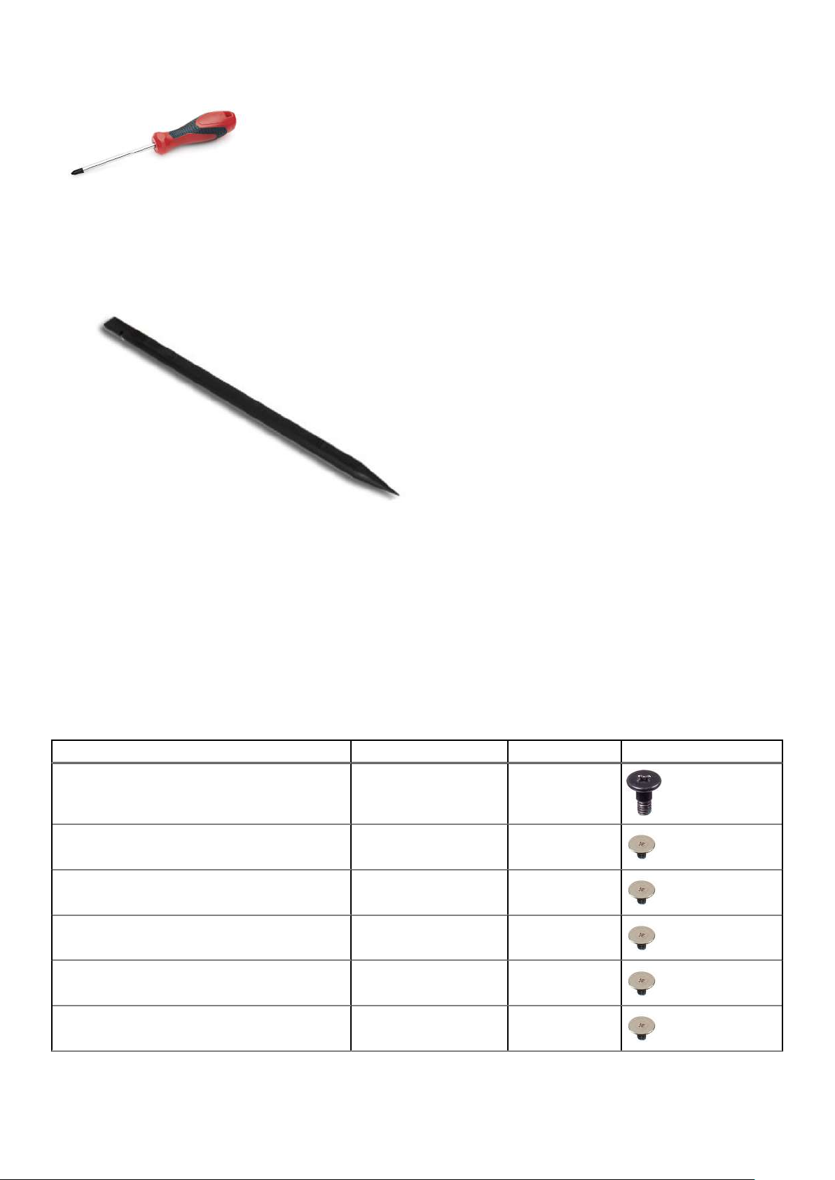
The procedures in this document may require the following tools:
● Phillips #0 screwdriver
● Plastic scribe
Removing and installing components 11
Page 12
Screw List
The following table shows the screw list and the image of the screws.
Table 1. Screw list
Component Screw type Quantity Image
Base cover Captive screws 9
3-cell battery M2x3 3
4-cell battery M2x3 5
M.2 Solid-state drive bracket M2x3 1
M.2 Solid-state drive thermal plate M2x3 1
M.2 Solid-state drive conversion bracket M2x3 2
12 Removing and installing components
Page 13
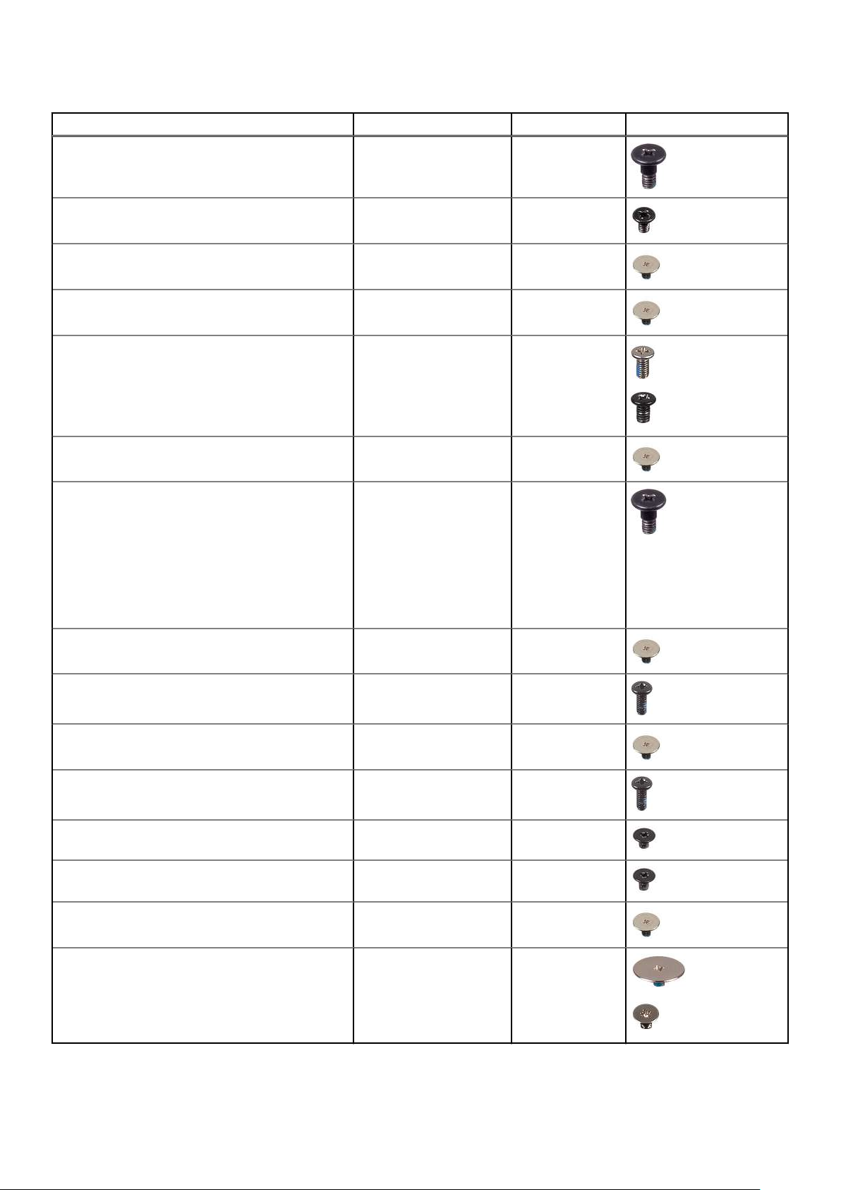
Table 1. Screw list
Component Screw type Quantity Image
Hard disk-drive module
Hard disk-drive M3x3 4
WLAN card M2x3 1
WWAN card M2x3 1
Display hinges M2.5x6
System Fan M2x3 2
Heatsink assembly
Captive screws
M2.5x4
Captive screws
4
6
1
7 (For systems
enabled with
discrete graphic
card)
4 (For systems
enabled with
integrated graphic
card)
Power adapter port M2x3 1
Ethernet port M2x5 2
I/O board M2x3 2
System board M2x5 2
Touchpad bracket M2.5x2 3
Touchpad module M2x2 4
WWAN I/O board M2x3 2
Hinge bracket M2.5x2.5
M2.5x3
6
2
Removing and installing components 13
Page 14
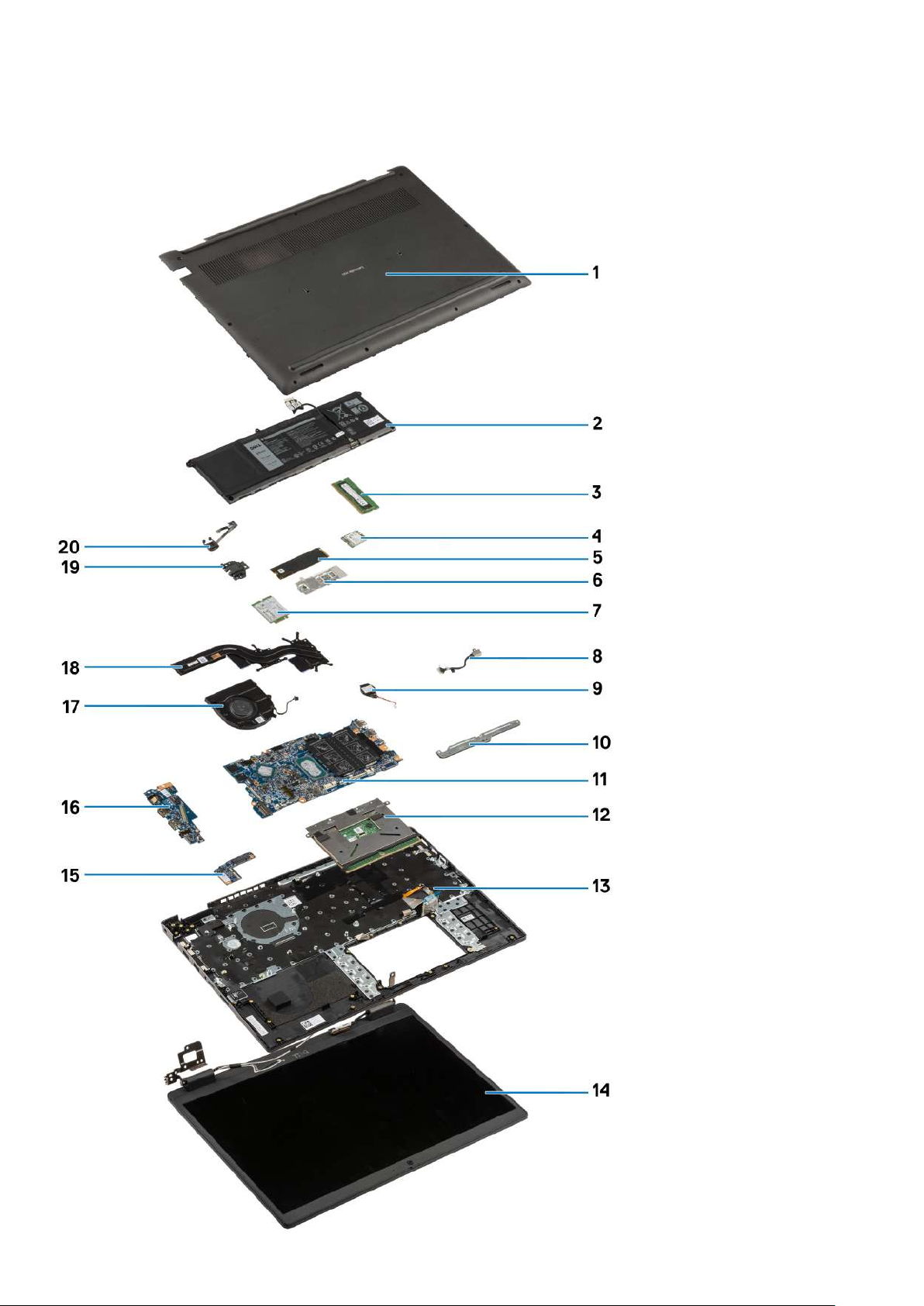
Major components of your system
14 Removing and installing components
Page 15
1. Base cover
2. Battery
3. Memory module
4. WLAN card
5. Solid-state drive
6. Solid-state drive conversion bracket
7. WWAN card
8. Power adapter port
9. Coin-cell battery
10. Touchpad bracket
11. System board
12. Touchpad
13. Computer chassis
14. Display assembly
15. WWAN I/O board
16. I/O board
17. System fan
18. Heatsink assembly
19. Ethernet port
20. Power-button board
NOTE: Dell provides a list of components and their part numbers for the original system configuration purchased. These
parts are available according to warranty coverages purchased by the customer. Contact your Dell sales representative for
purchase options.
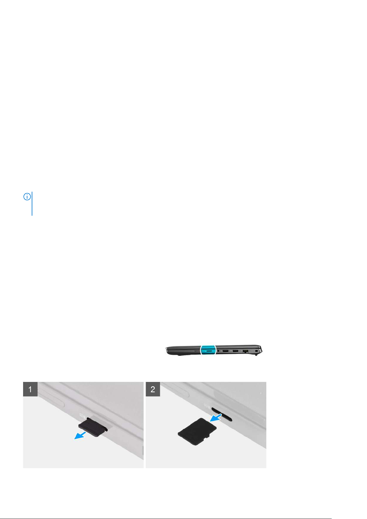
MicroSD-card
Removing the microSD-card
Prerequisites
1. Follow the procedure in before working inside your computer.
About this task
The following image provides a visual representation of the microSD-card removal procedure.
Removing and installing components
15
Page 16
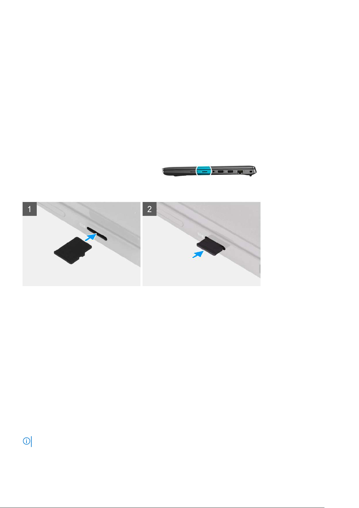
Steps
1. Push the microSD-card to eject it from the slot.
2. Remove the microSD-card from the system.
Installing the MicroSD-card
Prerequisites
If you are replacing a component, remove the existing component before performing the installation procedure.
About this task
The following image provides a visual representation of the MicroSD-card installation procedure.
Steps
Insert the microSD-card into its slot until it clicks into place.
Next steps
1. Follow the procedure in after working inside your computer.
SIM card tray
Removing the SIM card tray
Prerequisites
1. Follow the procedure in before working inside your computer.
2. Remove the microSD-card.
About this task
NOTE: The following steps are applicable only for 4G LTE enabled systems.
The following image provides a visual representation of the SIM card tray removal procedure.
16
Removing and installing components
Page 17
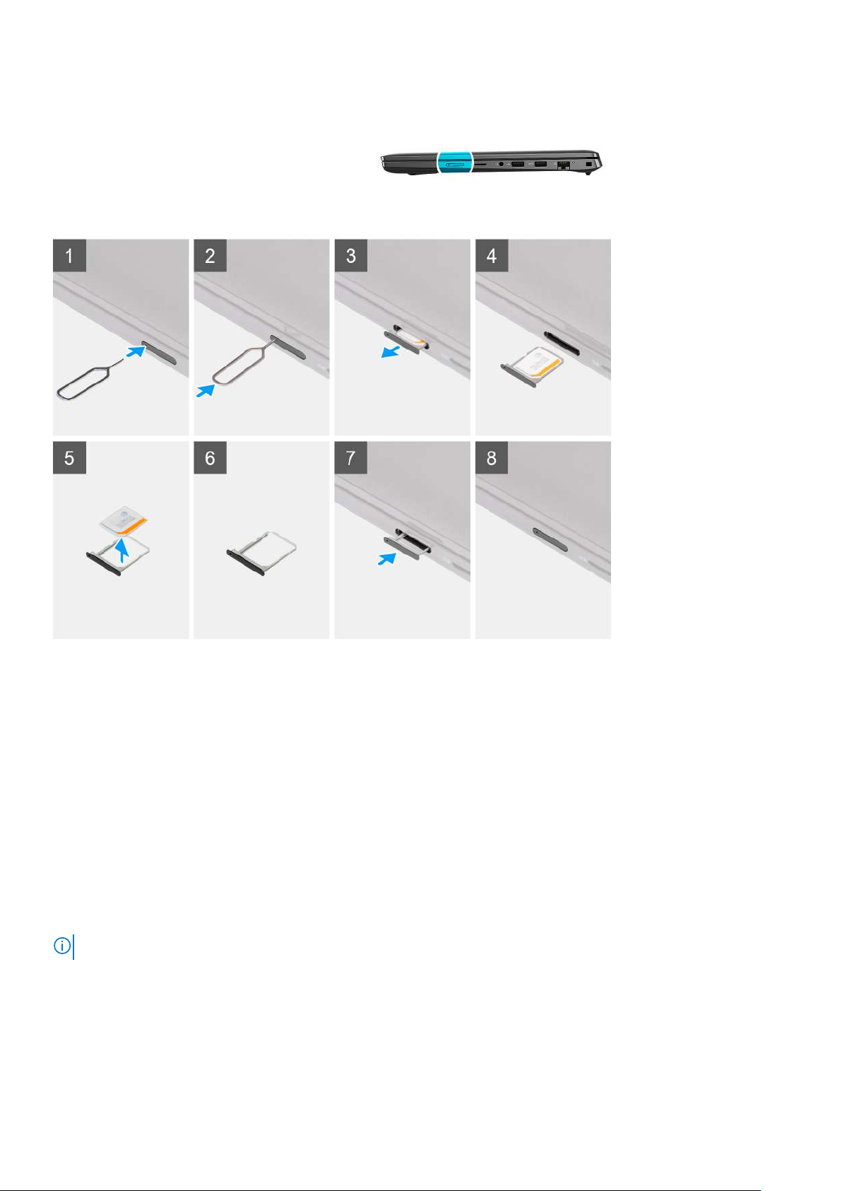
Steps
1. Insert the SIM card removal pin into the release hole to release the SIM card tray.
2. Push the pin to disengage the lock, and eject the SIM card tray.
3. Slide the SIM card tray out of the slot on the computer.
4. Remove the MicroSIM-card from the SIM tray.
5. Slide the SIM card tray back into the slot on the computer.
Installing the SIM card tray
Prerequisites
If you are replacing a component, remove the necessary component before the installation procedure.
About this task
NOTE: The following steps are applicable only for 4G LTE enabled systems.
The following image provides a visual representation of the SIM card tray installation procedure.
Removing and installing components
17
Page 18
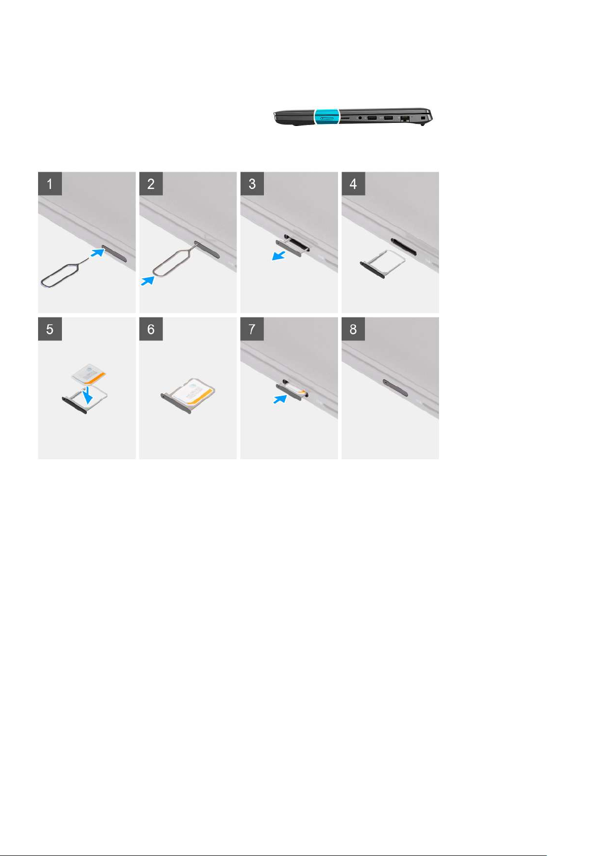
Steps
1. Insert the SIM card removal pin into the release hole to remove the SIM card tray.
2. Push the pin to disengage the lock, and eject the SIM card tray.
3. Slide the SIM card tray out of the slot on the computer.
4. Align and place the MicroSIM-card in the dedicated slot on the SIM card tray.
5. Slide the SIM card tray back into the slot on the computer.
Next steps
1. Install the microSD-card.
2. Follow the procedure in after working inside your computer.
Base cover
Removing the base cover
Prerequisites
1. Follow the procedure in before working inside your computer.
2. Remove the microSD-card.
3. Remove the SIM card tray for 4G LTE enabled systems.
4. Enter the service mode.
18
Removing and installing components
Page 19
About this task
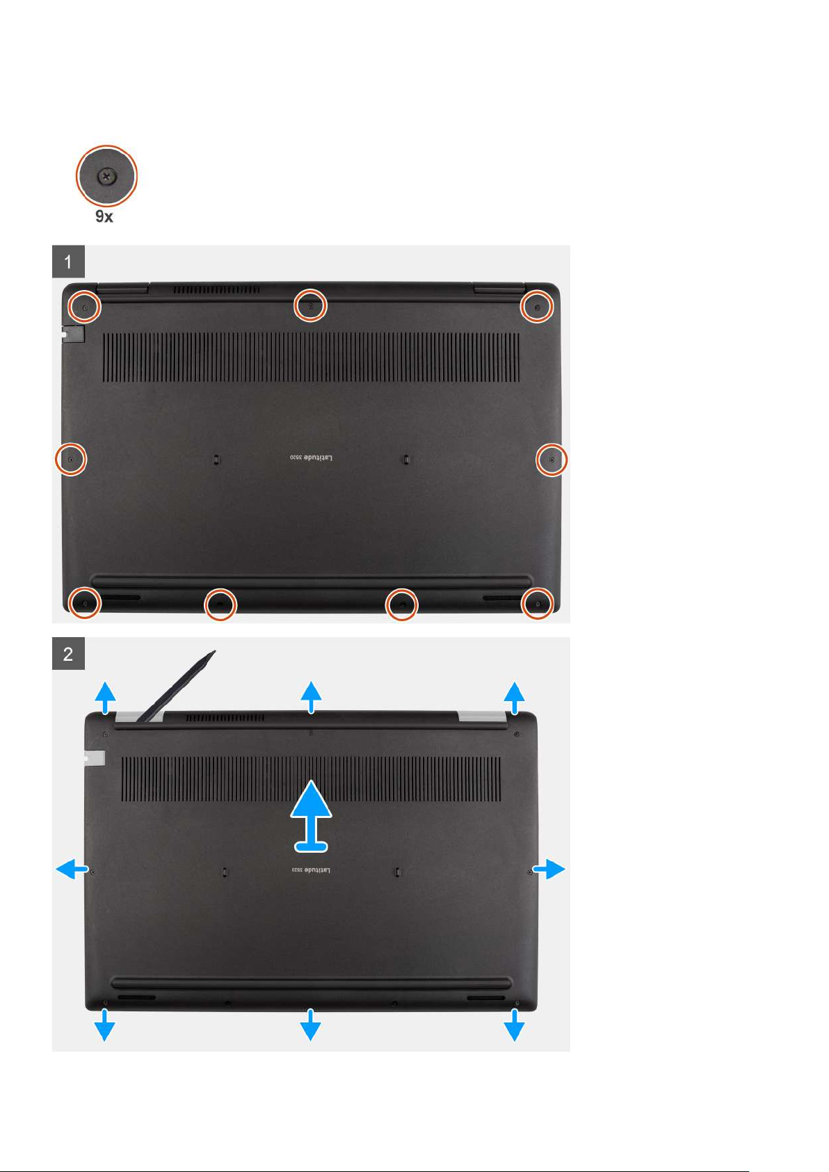
The following images indicate the location of the base cover and provide a visual representation of the removal procedure.
Removing and installing components 19
Page 20
Steps
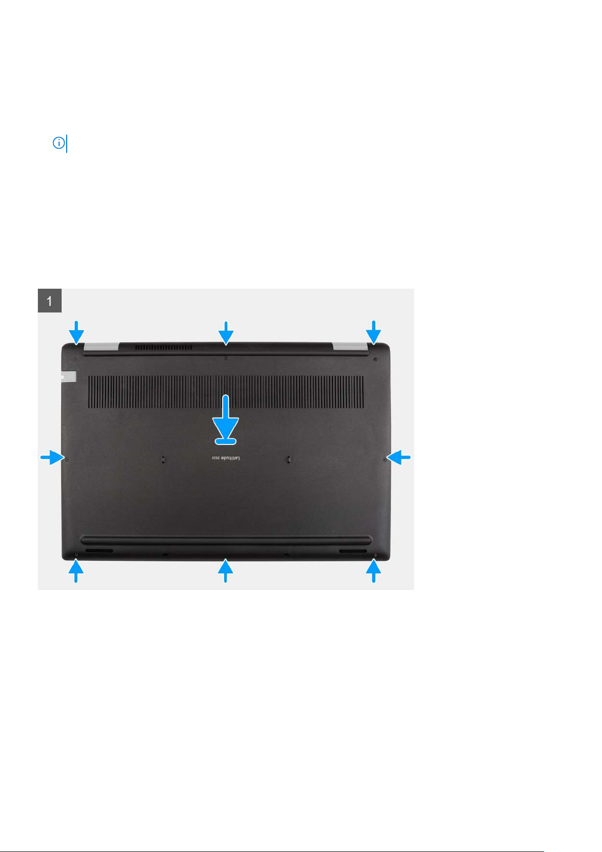
1. Loosen the nine captive screws that secure the base cover to the palmrest assembly.
2. Using a plastic scribe, pry open the base cover starting from the recesses located in the U-shaped indents near the hinges at
the top edge of the base cover.
3. Carefully lift and remove the base cover from the chassis.
NOTE: Be careful of the latches while removing the base cover as the latches may break.
Installing the base cover
Prerequisites
If you are replacing a component, remove the existing component before performing the installation procedure.
About this task
The following images indicate the location of the battery and provide a visual representation of the installation procedure.
20 Removing and installing components
Page 21
Steps
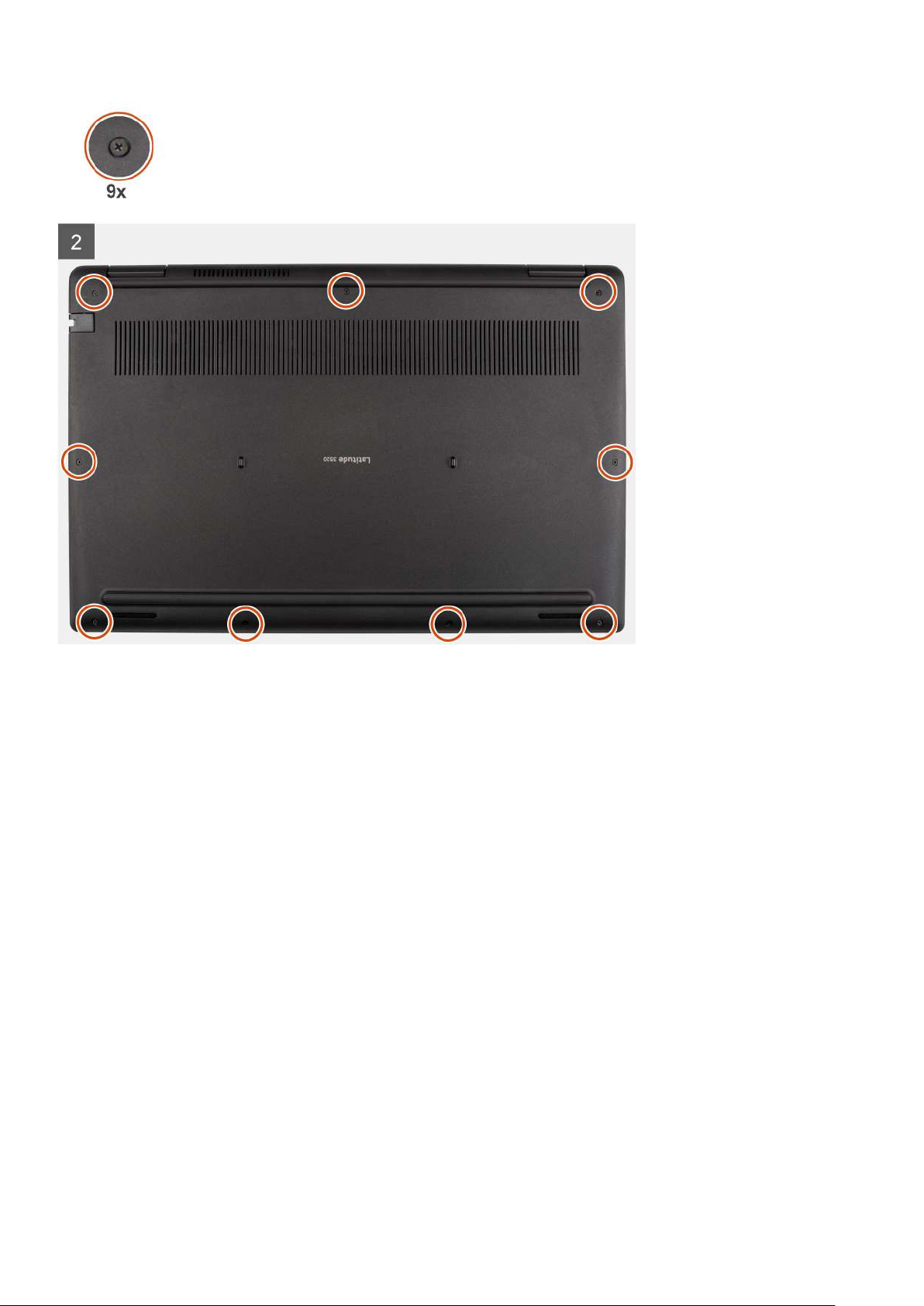
1. Align and place the base cover on the palmrest assembly, and snap the base cover latches into place.
2. Tighten the nine captive screws to secure the base cover to the computer chassis.
Next steps
1. Exit the service mode
2. Install the SIM card tray for 4G LTE enabled systems.
3. Install the microSD-card.
4. Follow the procedure in after working inside your computer.
Battery cable
Removing the battery cable
Prerequisites
1. Follow the procedure in before working inside your computer.
2. Remove the microSD-card.
3. Remove the SIM card tray for 4G LTE enabled systems.
4. Remove the base cover.
About this task
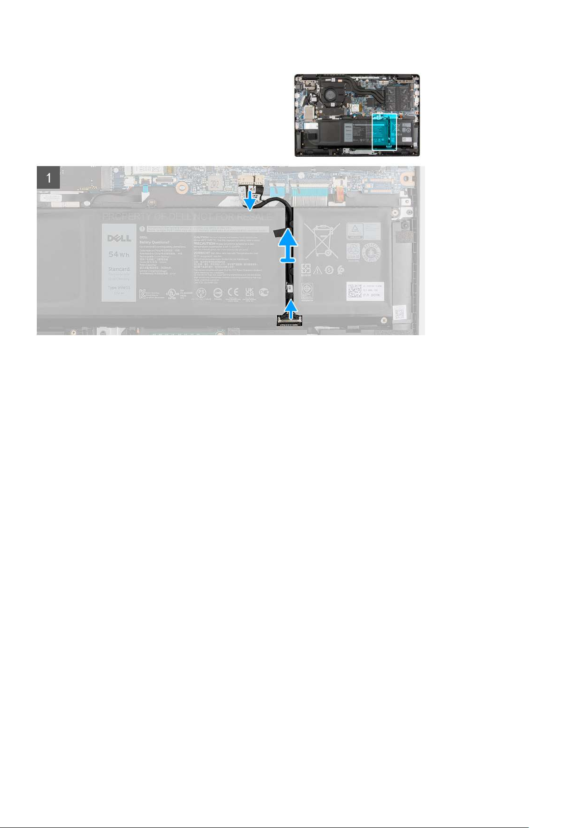
The following image indicates the location of the battery cable and provides a visual representation of the removal procedure.
Removing and installing components
21
Page 22
Steps
1. Disconnect the battery cable from the connector on the system board.
2. Peel the adhesive tapes and unroute the battery cable from routing channel in the battery.
3. Disconnect the battery cable from the connector on the battery.
Installing the battery cable
Prerequisites
If you are replacing a component, remove the existing component before performing the installation procedure.
About this task
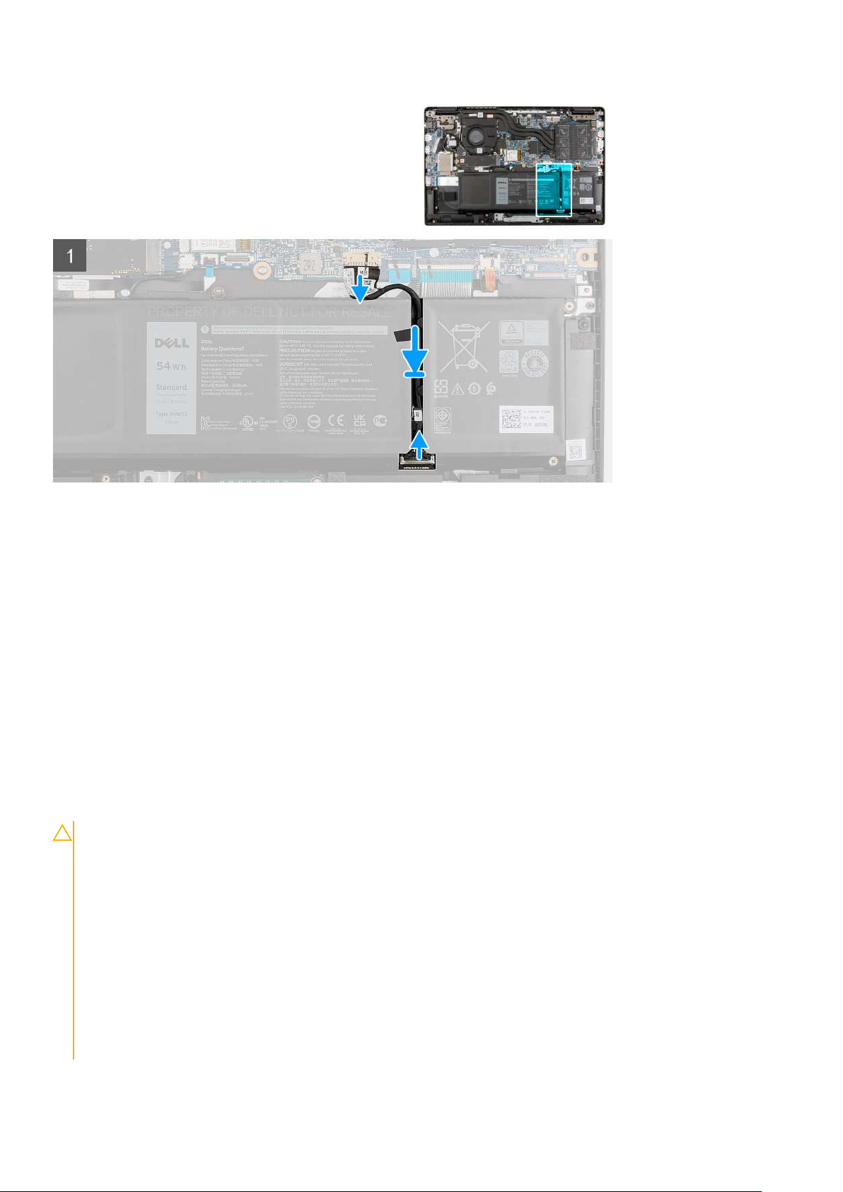
The following image indicates the location of the battery cable and provides a visual representation of the installation procedure.
22
Removing and installing components
Page 23
Steps
1. Connect the battery cable to the connector on the battery.
2. Route the battery cable through the routing channel in the battery and adhere the adhesive tapes.
3. Connect the battery cable to the connector on the system board.
Next steps
1. Install the base cover.
2. Install the SIM card tray for 4G LTE enabled systems.
3. Install the microSD-card.
4. Follow the procedure in after working inside your computer.
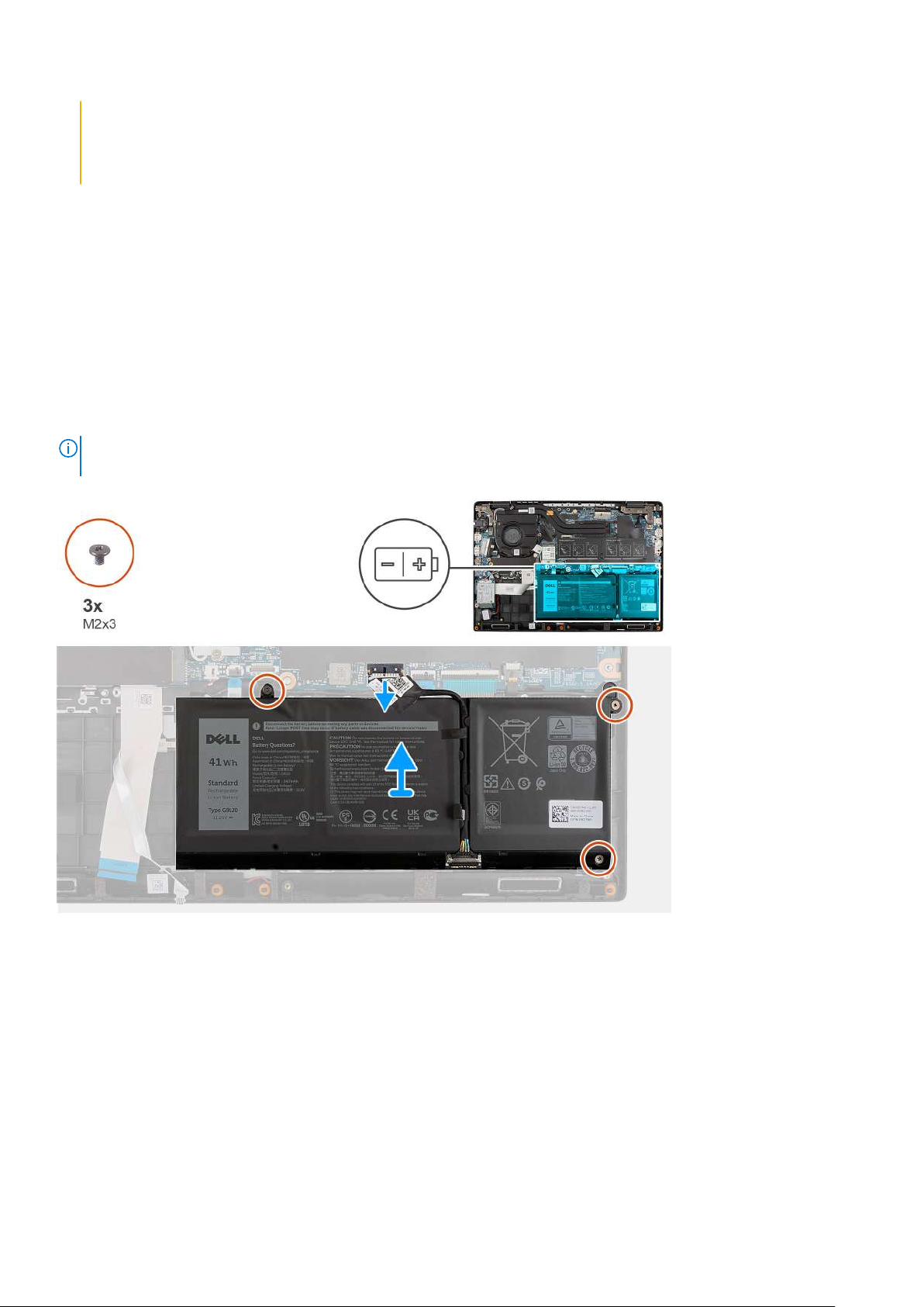
Battery
Lithium-ion battery precautions
CAUTION:
● Exercise caution when handling Lithium-ion batteries.
● Discharge the battery completely before removing it. Disconnect the AC power adapter from the system and
operate the computer solely on battery power—the battery is fully discharged when the computer no longer
turns on when the power button is pressed.
● Do not crush, drop, mutilate, or penetrate the battery with foreign objects.
● Do not expose the battery to high temperatures, or disassemble battery packs and cells.
● Do not apply pressure to the surface of the battery.
● Do not bend the battery.
● Do not use tools of any kind to pry on or against the battery.
● Ensure any screws during the servicing of this product are not lost or misplaced, to prevent accidental
puncture or damage to the battery and other system components.
Removing and installing components 23
Page 24
● If the battery gets stuck inside your computer as a result of swelling, do not try to release it as puncturing,
bending, or crushing a lithium-ion battery can be dangerous. In such an instance, contact Dell technical
support for assistance. See www.dell.com/contactdell.
● Always purchase genuine batteries from www.dell.com or authorized Dell partners and resellers.
Removing the 3-cell battery
Prerequisites
1. Follow the procedure in before working inside your computer.
2. Remove the microSD-card.
3. Remove the SIM card tray for 4G LTE enabled systems.
4. Remove the base cover.
About this task
The following image indicates the location of the battery and provides a visual representation of the removal procedure.
NOTE: If the battery was disconnected from system board for service, there will be a delay during system boot as the
system undergoes RTC battery reset.
Steps
1. Disconnect the battery cable from the connector on the system board.
2. Remove the three (M2X3) screws that secure the battery in place.
3. Lift and remove the battery from the palmrest assembly.
Installing the 3-cell battery
Prerequisites
If you are replacing a component, remove the existing component before performing the installation procedure.
24
Removing and installing components
Page 25
About this task
The following image indicates the location of the battery and provides a visual representation of the installation procedure.
NOTE: If the battery was disconnected from system board for service, there will be a delay during system boot as the
system undergoes RTC battery reset.
Steps
1. Align and place the battery in the slot on the palmrest assembly.
2. Install the three (M2X3) screws to secure the battery in place.
3. Connect the battery cable to the connector on the system board.
Next steps
1. Install the base cover.
2. Install the SIM card tray for 4G LTE enabled systems.
3. Install the microSD-card.
4. Follow the procedure in after working inside your computer.
Removing the 4-cell battery
Prerequisites
1. Follow the procedure in before working inside your computer.
2. Remove the microSD-card.
3. Remove the SIM card tray for 4G LTE enabled systems.
4. Remove the base cover.
About this task
The following image indicates the location of the battery and provides a visual representation of the removal procedure.
If the battery was disconnected from system board for service, there will be a delay during system boot as the
NOTE:
system undergoes RTC battery reset.
Removing and installing components 25
Page 26
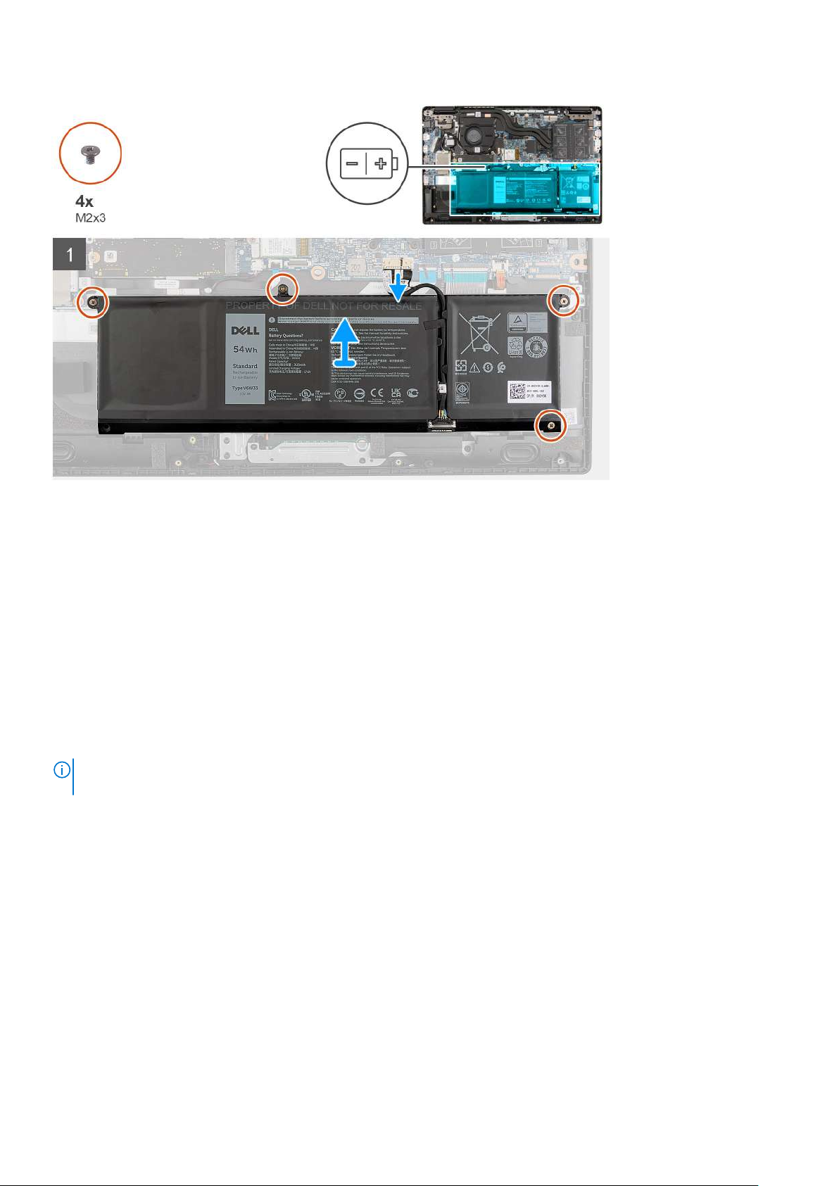
Steps
1. Disconnect the battery cable from the connector on the system board.
2. Remove the four (M2X3) screws that secure the battery in place.
3. Lift and remove the battery from the palmrest assembly.
Installing the 4-cell battery
Prerequisites
If you are replacing a component, remove the existing component before performing the installation procedure.
About this task
The following image indicates the location of the battery and provides a visual representation of the installation procedure.
NOTE:
If the battery was disconnected from system board for service, there will be a delay during system boot as the
system undergoes RTC battery reset.
26 Removing and installing components
Page 27

Steps
1. Align and place the battery in the slot on the palmrest assembly.
2. Install the four (M2X3) screws to secure the battery in place.
3. Connect the battery cable to the connector on the system board.
Next steps
1. Install the base cover.
2. Install the SIM card tray for 4G LTE enabled systems.
3. Install the microSD-card.
4. Follow the procedure in after working inside your computer.
Memory module
Removing the memory module
Prerequisites
1. Follow the procedure in before working inside your computer.
2. Remove the microSD-card.
3. Remove the SIM card tray for 4G LTE enabled systems.
4. Enter the service mode.
5. Remove the base cover.
About this task
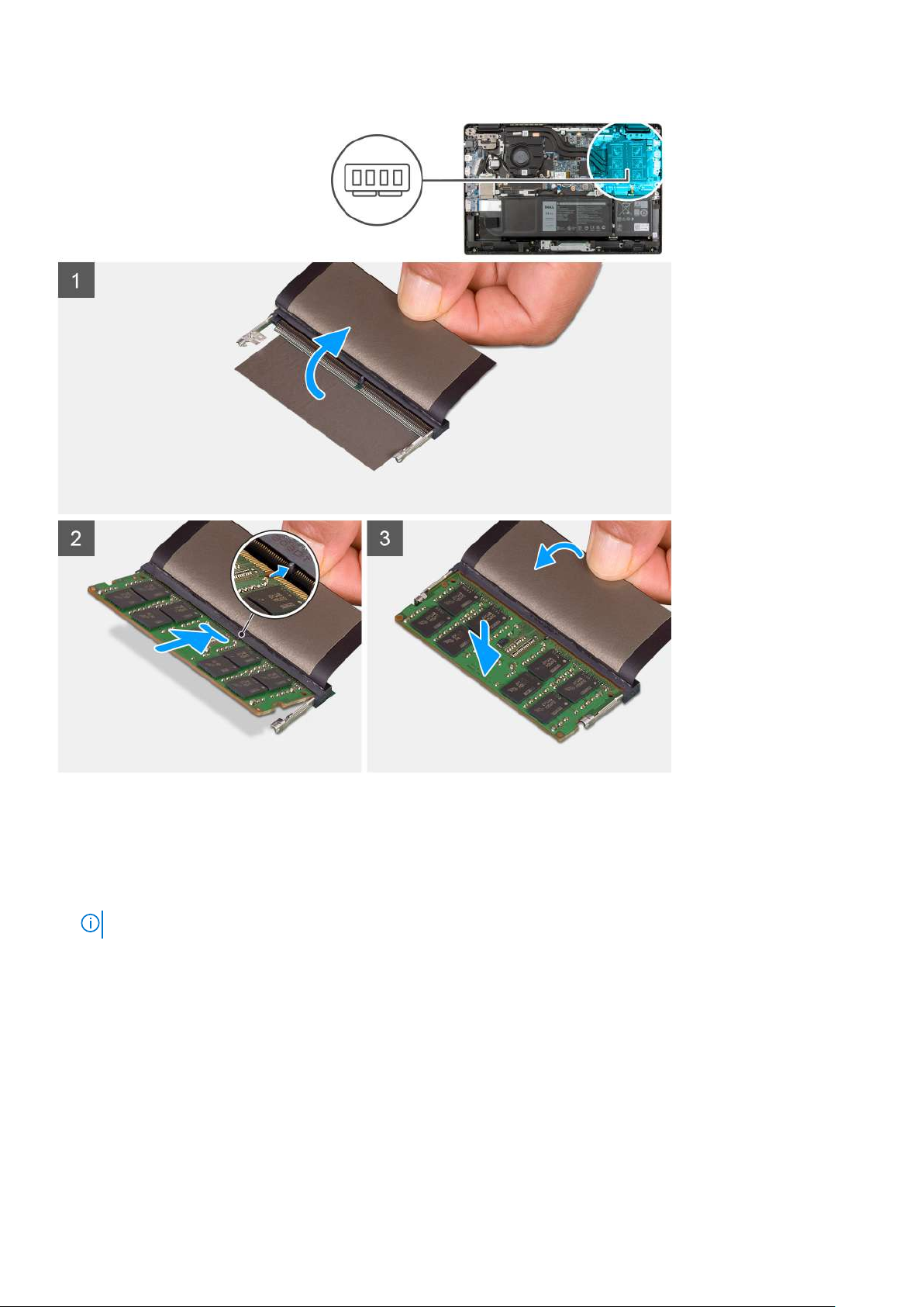
The following image indicates the location of the memory module and provides a visual representation of the removal procedure.
Removing and installing components
27
Page 28
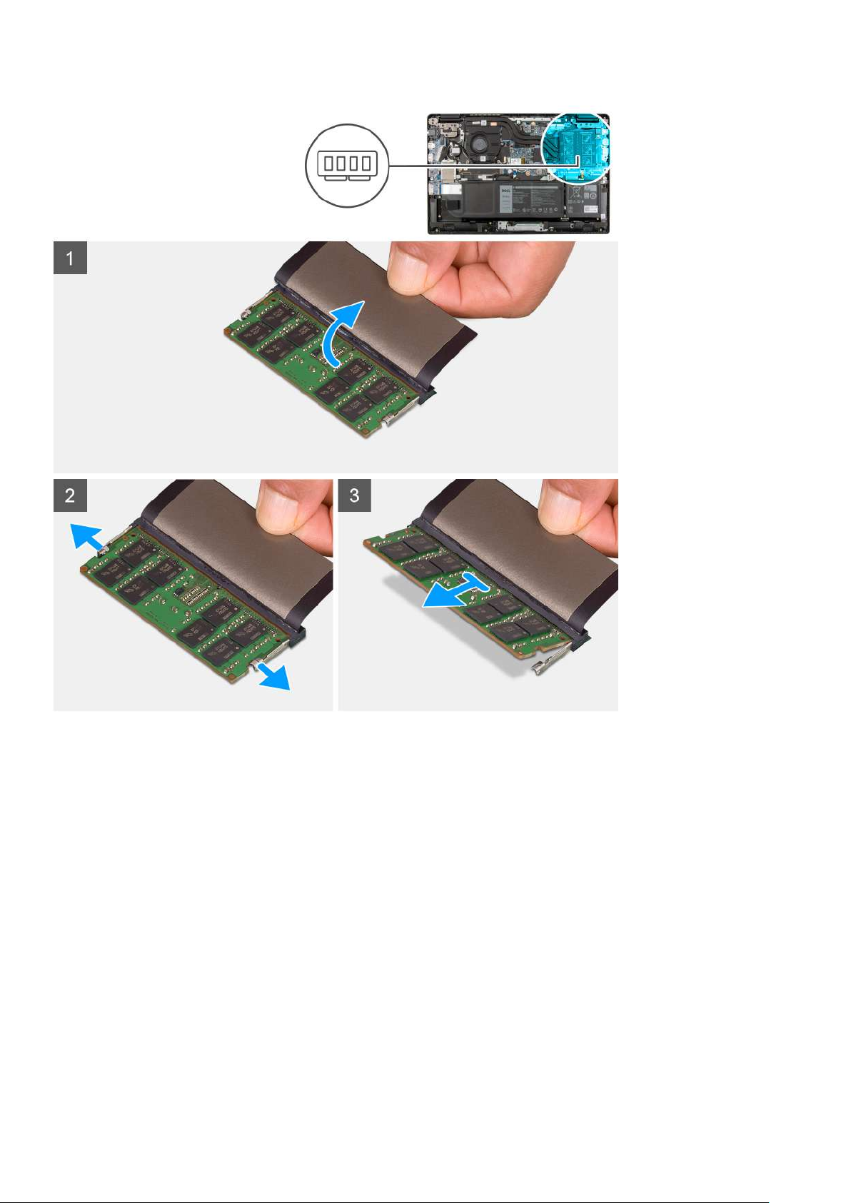
Steps
1. Lift the mylar to uncover the memory module.
2. Pry the retention clips securing the memory module slot until the memory module pops-up.
3. Remove the memory module from the memory module slot.
Installing the memory module
Prerequisites
If you are replacing a component, remove the existing component before performing the installation procedure.
About this task
The following image indicates the location of the memory module and provides a visual representation of the installation
procedure.
28
Removing and installing components
Page 29
Steps
1. Lift the mylar to find the memory module slot.
2. Align the notch on the memory module with the tab on the memory-module slot.
3. Slide the memory module firmly into the slot at an angle.
4. Press the memory module down until it clicks into place.
NOTE: If you do not hear the click, remove the memory module and reinstall it.
Next steps
1. Install the base cover.
2. Exit the service mode
3. Install the SIM card tray for 4G LTE enabled systems.
4. Install the microSD-card.
5. Follow the procedure in after working inside your computer.
Removing and installing components
29
Page 30
M.2 solid-state drive thermal plate
Replacing the M.2 solid-state drive thermal plate
Prerequisites
1. Follow the procedure in before working inside your computer.
2. Remove the microSD-card.
3. Remove the SIM card tray for 4G LTE enabled systems.
4. Enter the service mode.
5. Remove the base cover.
About this task
The following image indicates the location of the M.2 solid-state drive thermal plate and provides a visual representation of the
removal procedure.
NOTE: The following is applicable only for systems shipped with discrete graphic card.
Steps
1. Remove the (M2x3) screw that secures the solid-state drive thermal plate to the solid-state drive conversion bracket.
2. Depending on the type of solid-state drive (M.2 2230/ M.2 2280), turn, align and place the solid-state drive thermal plate
into the slot.
30
Removing and installing components
Page 31

3. Install the (M2x3) screw to secure the solid-state drive thermal plate to the solid-state drive conversion bracket.
M.2 solid-state drive conversion bracket
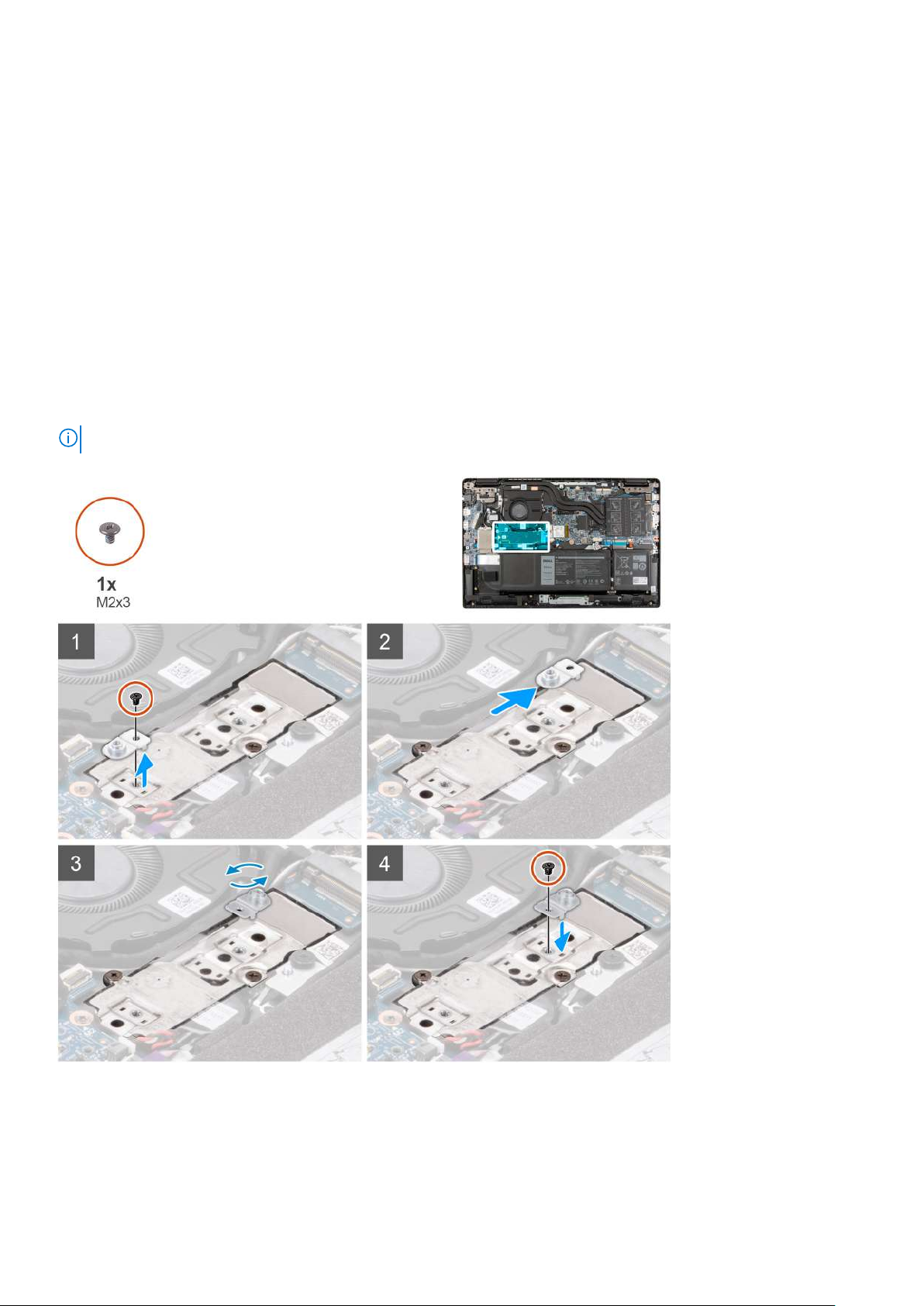
Removing the M.2 solid-state drive conversion bracket
Prerequisites
1. Follow the procedure in before working inside your computer.
2. Remove the microSD-card.
3. Remove the SIM card tray for 4G LTE enabled systems.
4. Enter the service mode.
5. Remove the base cover.
About this task
The following image indicates the location of the M.2 solid-state drive conversion bracket and provides a visual representation
of the removal procedure.
NOTE: The following is applicable only for systems shipped with discrete graphic card.
Steps
1. Remove the two (M2x3) screws that secures the solid-state drive conversion bracket to the system board.
2. Lift and remove the solid-state drive conversion bracket from the solid-state drive slot on the system board.
Installing the M.2 solid-state drive conversion bracket
Prerequisites
If you are replacing a component, remove the existing component before performing the installation procedure.
About this task
The following image indicates the location of the M.2 solid-state drive conversion bracket and provides a visual representation
of the installation procedure.
NOTE: The following is applicable only for systems shipped with discrete graphic card.
Removing and installing components 31
Page 32

Steps
1. Align and place the solid-state drive conversion bracket on the system board.
2. Install the two (M2x3) screws to secure the solid-state drive conversion bracket to the system board.
Next steps
1. Install the base cover.
2. Exit the service mode
3. Install the SIM card tray for 4G LTE enabled systems.
4. Install the microSD-card.
5. Follow the procedure in after working inside your computer.
M.2 solid-state drive
Removing the M.2 2230 solid-state drive
Prerequisites
1. Follow the procedure in before working inside your computer.
2. Remove the microSD-card.
3. Remove the SIM card tray for 4G LTE enabled systems.
4. Enter the service mode.
5. Remove the base cover.
About this task
The following image indicates the location of the solid-state drive and provides a visual representation of the removal procedure.
32
Removing and installing components
Page 33

Steps
1. Remove the (M2x3) screw that secures the solid-state drive to the system board.
2. Slide and remove the solid-state drive from the solid-state drive slot on the system board.
Installing the M.2 2230 solid-state drive
Prerequisites
If you are replacing a component, remove the existing component before performing the installation procedure.
About this task
The following image indicates the location of the solid-state drive and provides a visual representation of the installation
procedure.
Steps
1. Align the notch on the solid-state drive with the tab on the solid-state drive slot.
Removing and installing components
33
Page 34

2. Slide the solid-state drive into the solid-state drive slot on the system board.
3. Replace the (M2x3) screw to secure the solid-state drive to the system board.
Next steps
1. Install the base cover.
2. Exit the service mode
3. Install the SIM card tray for 4G LTE enabled systems.
4. Install the microSD-card.
5. Follow the procedure in after working inside your computer.
Removing the M.2 2280 solid-state drive
Prerequisites
1. Follow the procedure in before working inside your computer.
2. Remove the microSD-card.
3. Remove the SIM card tray for 4G LTE enabled systems.
4. Enter the service mode.
5. Remove the base cover.
About this task
The following image indicates the location of the solid-state drive and provides a visual representation of the removal procedure.
Steps
1. Remove the (M2x3) screw that secures the solid-state drive to the system board.
2. Slide and remove the solid-state drive from the solid-state drive slot on the system board.
Installing the M.2 2280 solid-state drive
Prerequisites
If you are replacing a component, remove the existing component before performing the installation procedure.
34
Removing and installing components
Page 35

About this task
The following image indicates the location of the solid-state drive and provides a visual representation of the installation
procedure.
Steps
1. Align the notch on the solid-state drive with the tab on the solid-state drive slot.
2. Slide the solid-state drive into the solid-state drive slot on the system board.
3. Replace the (M2x3) screw to secure the solid-state drive to the system board.
Next steps
1. Install the base cover.
2. Exit the service mode
3. Install the SIM card tray for 4G LTE enabled systems.
4. Install the microSD-card.
5. Follow the procedure in after working inside your computer.
Hard-disk drive
Removing the hard-disk drive
Prerequisites
1. Follow the procedure in before working inside your computer.
2. Remove the microSD-card.
3. Remove the SIM card tray for 4G LTE enabled systems.
4. Enter the service mode.
5. Remove the base cover.
About this task
The following image indicates the location of the hard-disk drive and provides a visual representation of the removal procedure.
Removing and installing components
35
Page 36

Steps
1. Lift and disconnect the hard-disk drive cable from the connector on the system board.
2. Loosen the four captive screws that secure the hard-disk drive module to the palmrest assembly.
3. Lift and remove the hard-disk drive module from the slot on the palmrest assembly.
Removing the hard-disk drive bracket
Prerequisites
1. Follow the procedure in before working inside your computer.
2. Remove the microSD-card.
3. Remove the SIM card tray for 4G LTE enabled systems.
4. Enter the service mode.
5. Remove the base cover.
6. Remove the hard-disk drive.
About this task
The following image indicates the location of the hard-disk drive bracket and provides a visual representation of the removal
procedure.
36
Removing and installing components
Page 37

Steps
1. Disconnect the hard-disk drive cable from the connector on the hard-disk drive bracket.
2. Remove the four (M3x3) screws that secure the hard-disk drive to the hard-disk drive bracket.
3. Flip the hard-disk drive bracket, lift the silver foil, and remove the hard-disk drive from the hard-disk drive bracket.
Installing the hard-disk drive bracket
Prerequisites
If you are replacing a component, remove the existing component before performing the installation procedure.
About this task
The following image indicates the location of the hard-disk drive bracket and provides a visual representation of the installation
procedure.
Removing and installing components
37
Page 38

Steps
1. Lift the silver foil, align and place the hard-disk drive in the hard-disk drive bracket.
2. Install the four (M3x3) screws to secure the hard-disk drive to the hard-disk drive bracket.
3. Connect the hard-disk drive cable to the connector on the hard-disk drive bracket.
Next steps
1. Install the hard-disk drive.
2. Install the base cover.
3. Exit the service mode
4. Install the SIM card tray for 4G LTE enabled systems.
5. Install the microSD-card.
6. Follow the procedure in after working inside your computer.
Installing the hard-disk drive
Prerequisites
If you are replacing a component, remove the existing component before performing the installation procedure.
38
Removing and installing components
Page 39

About this task
The following image indicates the location of the hard-disk drive and provides a visual representation of the installation
procedure.
NOTE: Systems that are shipped with 3-cell battery contain a rubber bumper that must be removed manually before
installing the hard-disk drive.
Steps
1. Align and place the hard-disk drive module in the slot on the palmrest assembly.
2. Tighten the four captive screws to secure the hard-disk drive module to the palmrest assembly.
3. Connect the hard-disk drive cable to the connector on the system board.
Next steps
1. Install the base cover.
2. Exit the service mode
3. Install the SIM card tray for 4G LTE enabled systems.
4. Install the microSD-card.
5. Follow the procedure in after working inside your computer.
WLAN card
Removing the WLAN card
Prerequisites
1. Follow the procedure in before working inside your computer.
2. Remove the microSD-card.
3. Remove the SIM card tray for 4G LTE enabled systems.
4. Enter the service mode.
5. Remove the base cover.
Removing and installing components
39
Page 40

About this task
The following image indicates the location of the WLAN card and provides a visual representation of the removal procedure.
Steps
1. Remove the screw (M2x3) that secures WLAN card bracket to the WLAN card on the system board.
2. Lift and remove the WLAN card bracket from the WLAN card that secures the two antenna cables.
3. Disconnect the antenna cables from the connectors on the WLAN card.
4. Disconnect and remove the WLAN card from the WLAN card slot.
Installing the WLAN card
Prerequisites
If you are replacing a component, remove the existing component before performing the installation procedure.
About this task
The following image indicates the location of the WLAN card and provides a visual representation of the installation procedure.
40
Removing and installing components
Page 41

Steps
1. Connect the two antenna cables to the connectors on the WLAN card.
NOTE: The antenna cable connectors are fragile and utmost care should be taken while replacing them.
Table 2. Antenna cable guide
Cable color Connector
White cable (Main) White triangle (△) on the WLAN module of the system
board
Black cable (Aux) Solid triangle (▲) on the WLAN module of the system board
2. Align the notch on the WLAN card with the tab on the WLAN card slot.
3. Slide the WLAN card at an angle into the WLAN card slot.
4. Align and place the WLAN card bracket on the WLAN card.
5. Install the screw (M2x3) to secure the WLAN card bracket on the WLAN card to the system board.
Next steps
1. Install the base cover.
Removing and installing components
41
Page 42

2. Exit the service mode
3. Install the SIM card tray for 4G LTE enabled systems.
4. Install the microSD-card.
5. Follow the procedure in after working inside your computer.
WWAN card
Removing the WWAN card
Prerequisites
1. Follow the procedure in before working inside your computer.
2. Remove the microSD-card.
3. Remove the SIM card tray for 4G LTE enabled systems.
4. Enter the service mode.
5. Remove the base cover.
About this task
The following image indicates the location of the WWAN card and provides a visual representation of the removal procedure.
NOTE: The following steps are applicable only for 4G LTE enabled systems.
42 Removing and installing components
Page 43

Steps
1. Remove the screw (M2x3) that secures WWAN card bracket to the WWAN card on the system board.
2. Lift and remove the WWAN card bracket from the WWAN card that secures the two antenna cables.
3. Disconnect the antenna cables from the connectors on the WWAN card.
4. Disconnect and remove the WWAN card from the WWAN card slot.
Installing the WWAN card
Prerequisites
If you are replacing a component, remove the existing component before performing the installation procedure.
About this task
The following image indicates the location of the WWAN card and provides a visual representation of the installation procedure.
NOTE: The following steps are applicable only for 4G LTE enabled systems.
Steps
1. Connect the two antenna cables to the connectors on the WWAN card.
NOTE: The antenna cable connectors are fragile and utmost care should be taken while replacing them.
Table 3. Antenna cable guide
Removing and installing components 43
Page 44

Table 3. Antenna cable guide
Cable color Connector
White cable (Main) White triangle (△) on the WLAN module of the system
board
Black cable (Aux) Solid triangle (▲) on the WLAN module of the system board
2. Align the notch on the WWAN card with the tab on the WWAN card slot.
3. Slide the WWAN card at an angle into the WWAN card slot.
4. Align and place the WLAN card bracket on the WLAN card.
5. Install the screw (M2x3) to secure the WLAN card bracket on the WLAN card to the system board.
Next steps
1. Install the base cover.
2. Exit the service mode
3. Install the SIM card tray for 4G LTE enabled systems.
4. Install the microSD-card.
5. Follow the procedure in after working inside your computer.
I/O cable
Removing the I/O cable
Prerequisites
1. Follow the procedure in before working inside your computer.
2. Remove the SIM card tray for 4G LTE enabled systems.
3. Enter the service mode.
4. Remove the base cover.
About this task
The following image indicates the location of the I/O cable and provides a visual representation of the removal procedure.
44
Removing and installing components
Page 45

Steps
1. Peel the adhesive tape, open the latch and disconnect the I/O cable from the connector on the system board.
2. Peel the adhesive tape and unroute the I/O cable from the routing guides in the palmrest assembly.
3. Peel the adhesive tape, open the latch and disconnect the I/O cable from the connector on the I/O board.
4. Lift and remove the I/O cable from the palmrest assembly.
Installing the I/O cable
Prerequisites
If you are replacing a component, remove the existing component before performing the installation procedure.
About this task
The following image indicates the location of the I/O cable and provides a visual representation of the installation procedure.
Removing and installing components
45
Page 46

Steps
1. Route the I/O cable through the routing guides and adhere the adhesive tape to secure the I/O cable in place.
2. Adhere the adhesive tape, connect the I/O cable to the connector on the system board, and close the latch.
3. Adhere the adhesive tape, connect the I/O cable to the connector on the I/O board, and close the latch.
Next steps
1. Install the base cover.
2. Exit the service mode
3. Install the microSD-card.
4. Install the SIM card tray for 4G LTE enabled systems.
5. Follow the procedure in after working inside your computer.
Display assembly
Removing the display assembly
Prerequisites
1. Follow the procedure in before working inside your computer.
2. Remove the microSD-card.
3. Remove the SIM card tray for 4G LTE enabled systems.
4. Enter the service mode.
5. Remove the base cover.
6. Remove the WLAN card.
7. Remove the WWAN card for systems enabled with 4G LTE.
8. Remove the I/O cable.
46
Removing and installing components
Page 47

About this task
The following images indicate the location of the display assembly and provide a visual representation of the removal procedure.
Removing and installing components 47
Page 48

Steps
1. Unroute the display cable from the routing guides in the palmrest assembly.
2. Peel the adhesive tape that secures the display cable in place.
3. Open the latch and disconnect the display cable from the connector on the system board.
4. Remove the (M2.5x4) and six (M2.5x6) screws that secure the display hinges to the system.
5. Lift the left and right hinges in upward direction away from the palmrest assembly.
6. Lift the display assembly off the palmrest assembly.
48
Removing and installing components
Page 49

Installing the display assembly
Prerequisites
If you are replacing a component, remove the existing component before performing the installation procedure.
About this task
The following images indicate the location of the display assembly and provide a visual representation of the installation
procedure.
Removing and installing components 49
Page 50

Steps
1. Align and place the system chassis under the hinges of the display assembly.
2. Press the left and right hinges in downward direction toward the palmrest assembly.
3. Install the (M2.5x4) and six (M2.5x6) screws to secure the display hinges to the palmrest assembly.
4. Connect the display cable to the connector on the system board and close the latch.
5. Route the display cable through the routing guides in the palmrest assembly.
6. Affix the adhesive tape to secures the display cable in place.
Next steps
1. Install the I/O cable.
2. Install the WWAN card for systems enabled with 4G LTE.
3. Install the WLAN card.
4. Install the base cover.
5. Exit the service mode
6. Install the SIM card tray for 4G LTE enabled systems.
7. Install the microSD-card.
8. Follow the procedure in after working inside your computer.
50
Removing and installing components
Page 51

System fan
Removing the system fan
Prerequisites
1. Follow the procedure in before working inside your computer.
2. Remove the microSD-card.
3. Remove the SIM card tray for systems enabled with 4G LTE.
4. Enter the service mode.
5. Remove the base cover.
About this task
The following image indicates the location of the system fan and provides a visual representation of the removal procedure.
Steps
1. Disconnect the system fan cable from the connector on the system board.
2. Remove the two (M2x3) screws that secure the system fan to the palmrest assembly.
3. Lift and remove the system fan from the palmrest assembly.
Installing the system fan
Prerequisites
If you are replacing a component, remove the existing component before performing the installation procedure.
Removing and installing components
51
Page 52

About this task
The following image indicates the location of the system fan and provides a visual representation of the installation procedure.
Steps
1. Align and place the system fan into the slot on the palmrest assembly.
2. Install the two (M2x3) screws to secure the system fan to the palmrest assembly.
3. Connect the system fan cable to the connector on the system board.
Next steps
1. Install the base cover.
2. Exit the service mode
3. Install the SIM card tray for systems enabled with 4G LTE.
4. Install the microSD-card.
5. Follow the procedure in after working inside your computer.
Heatsink assembly
Removing the heatsink assembly
Prerequisites
1. Follow the procedure in before working inside your computer.
2. Remove the microSD-card.
3. Remove the SIM card tray for systems enabled with 4G LTE.
4. Enter the service mode.
5. Remove the base cover.
52
Removing and installing components
Page 53

About this task
The following images indicate the location of the heatsink assembly and provide a visual representation of the removal
procedure.
NOTE: The following images are from systems shipped with discrete graphic card. The system board has a different
configuration for integrated graphic cards.
Steps
1. For systems enabled with integrated graphic card, loosen the four captive screws (in reverse order, 4->3->2->1) that secure
the heatsink assembly to the system board.
2. For systems enabled with discrete graphic card, loosen the seven captive screws (in reverse order, 7>6>5>4->3->2->1) that
secure the heatsink assembly to the system board.
3. Lift and remove the heatsink assembly from the system board.
Installing the heatsink assembly
Prerequisites
If you are replacing a component, remove the existing component before performing the installation procedure.
About this task
The following image indicates the location of the heatsink assembly and provides a visual representation of the installation
procedure.
The following images are from systems shipped with discrete graphic card. The system board has a different
NOTE:
configuration for integrated graphic cards.
Removing and installing components 53
Page 54

Steps
1. Align and place the heatsink assembly into the slot on the system board.
2. For systems enabled with integrated graphic card, tighten the four captive screws to secure the heatsink assembly to the
system board.
3. For systems enabled with discrete graphic card, tighten the seven captive screws to secure the heatsink assembly to the
system board.
Next steps
1. Install the base cover.
2. Exit the service mode
3. Install the SIM card tray for systems enabled with 4G LTE.
4. Install the microSD-card.
5. Follow the procedure in after working inside your computer.
Power adapter port
Removing the power adapter port
Prerequisites
1. Follow the procedure in before working inside your computer.
2. Remove the microSD-card.
3. Remove the SIM card tray for 4G LTE enabled systems.
4. Enter the service mode.
5. Remove the base cover.
54
Removing and installing components
Page 55

About this task
The following image indicates the location of the power adapter port and provides a visual representation of the removal
procedure.
Steps
1. Remove the (M2.5x4) and two (M2.5x6) screws that secure the display hinges to the system.
2. Disconnect the power adapter port from the connector on the system board.
3. Remove the (M2x3) screw that secures the power adapter port to the palmrest assembly.
4. Lift and remove the power adapter port from the palmrest assembly.
Installing the power adapter port
About this task
The following image indicates the location of the power adapter port and provides a visual representation of the removal
procedure.
Removing and installing components
55
Page 56

Steps
1. Align and place the power adapter port on the palmrest assembly.
2. Install the (M2x3) screw to secure the power adapter port to the palmrest assembly.
3. Connect the power adapter port to the connector on the system board.
4. Install the (M2.5x4) and two (M2.5x6) screws to secure the display hinges to the system.
Next steps
1. Install the base cover.
2. Exit the service mode
3. Install the SIM card tray for 4G LTE enabled systems.
4. Install the microSD-card.
5. Follow the procedure in after working inside your computer.
Coin-cell battery
Removing the coin-cell battery
Prerequisites
1. Follow the procedure in before working inside your computer.
2. Remove the microSD-card.
3. Remove the SIM card tray for 4G LTE enabled systems.
4. Enter the service mode.
5. Remove the base cover.
About this task
The following image indicates the location of the coin-cell battery and provides a visual representation of the removal procedure.
The following image is from computers with discrete graphic card. For computers with integrated graphic card, the
NOTE:
system board has a different configuration.
56 Removing and installing components
Page 57

Steps
1. Disconnect the coin-cell battery cable from the connector on the I/O board.
2. Lift and remove the coin-cell battery from the palmrest assembly.
Installing the coin-cell battery
Prerequisites
If you are replacing a component, remove the existing component before performing the installation procedure.
About this task
The following image indicates the location of the coin-cell battery and provides a visual representation of the installation
procedure.
NOTE:
The following image is from computers with discrete graphic card. For computers with integrated graphic card, the
system board has a different configuration.
Removing and installing components 57
Page 58

Steps
1. Align and place the coin-cell battery on the palmrest assembly.
2. Connect the coin-cell battery cable to the connector on the I/O board.
Next steps
1. Install the base cover.
2. Exit the service mode
3. Install the SIM card tray for 4G LTE enabled systems.
4. Install the microSD-card.
5. Follow the procedure in after working inside your computer.
USB cable
Removing the USB cable
Prerequisites
1. Follow the procedure in before working inside your computer.
2. Remove the microSD-card.
3. Remove the SIM card tray for 4G LTE enabled systems.
4. Remove the base cover.
5. Remove the battery.
6. Remove the hard-disk drive.
About this task
The following image indicates the location of the USB cable and provides a visual representation of the removal procedure.
58
Removing and installing components
Page 59

Steps
1. Open the latch and disconnect the USB cable from the connector on the system board.
2. Carefully peel the USB cable from the palmrest assembly.
3. Open the latch and disconnect the USB cable from the connector on the I/O board.
4. Lift and remove the USB cable from the palmrest assembly.
Installing the USB cable
Prerequisites
If you are replacing a component, remove the existing component before performing the installation procedure.
About this task
The following image indicates the location of the USB cable and provides a visual representation of the installation procedure.
Removing and installing components
59
Page 60

Steps
1. Connect the USB cable to the connector on the system board and close the latch.
2. Align and adhere the USB cable on the palmrest assembly.
3. Connect the USB cable to the connector on the I/O board and close the latch.
Next steps
1. Install the hard-disk drive.
2. Install the battery.
3. Install the base cover.
4. Install the SIM card tray for 4G LTE enabled systems.
5. Install the microSD-card.
6. Follow the procedure in after working inside your computer.
Ethernet port
Removing the ethernet port
Prerequisites
1. Follow the procedure in before working inside your computer.
2. Remove the microSD-card.
3. Remove the SIM card tray for 4G LTE enabled systems.
4. Enter the service mode.
5. Remove the base cover.
About this task
The following image indicates the location of the ethernet port and provides a visual representation of the removal procedure.
Steps
1. Remove the four (M2.5x6) screws to secure the hinge bracket on the palmrest assembly.
2. Lift the hinge in upward direction away from the palmrest assembly.
60
Removing and installing components
Page 61

3. Remove the two (M2x5) screws that secure the ethernet on the I/O board.
4. Lift and remove the ethernet from the I/O board.
Installing the ethernet port
Prerequisites
If you are replacing a component, remove the existing component before performing the installation procedure.
About this task
The following image indicates the location of the ethernet port and provides a visual representation of the installation procedure.
Steps
1. Align and place the ethernet on the I/O board.
2. Install the two (M2x5) screws to secure the ethernet on the I/O board.
3. Press the hinge in downward direction toward the palmrest assembly.
4. Install the four (M2.5x6) screws to secure the hinge bracket on the palmrest assembly.
Next steps
1. Install the base cover.
2. Exit the service mode
3. Install the SIM card tray for 4G LTE enabled systems.
4. Install the microSD-card.
5. Follow the procedure in after working inside your computer.
Removing and installing components
61
Page 62

I/O board
Removing the I/O board
Prerequisites
1. Follow the procedure in before working inside your computer.
2. Remove the microSD-card.
3. Remove the SIM card tray for 4G LTE enabled systems.
4. Enter the service mode.
5. Remove the base cover.
6. Remove the ethernet port.
About this task
NOTE: The following image is from computers with discrete graphic card. For computers with integrated graphic card, the
system board has a different configuration.
The following image indicates the location of the I/O board and provides a visual representation of the removal procedure.
Steps
1. For systems shipped with power-button board, peel the adhesive, open the latch and disconnect the power-button board
cable from the connector on the I/O board.
2. Open the latch and disconnect the I/O cable from the connector on the system board.
3. Disconnect the USB cable and coin-cell cable from the connectors on the system board.
4. Remove the two (M2x3) screws that secure the I/O board on the palmrest assembly.
5. Lift and remove the I/O board from the palmrest assembly.
62
Removing and installing components
Page 63

Installing the I/O board
Prerequisites
If you are replacing a component, remove the existing component before performing the installation procedure.
About this task
NOTE: The following image is from computers with discrete graphic card. For computers with integrated graphic card, the
system board has a different configuration.
The following image indicates the location of the I/O board and provides a visual representation of the installation procedure.
Steps
1. Align and place the I/O board into its slot on the palmrest assembly.
2. Install the two (M2x3) screws that secure the I/O board on the palmrest assembly.
3. Connect the USB cable and coin-cell cable to the connectors on the system board.
4. Connect the I/O cable to the connector on the system board and close the latch.
5. For systems shipped with power-button board, connect the power-button board cable to the connector on the I/O board,
close the latch and affix the adhesive tape.
Next steps
1. Install the ethernet port.
2. Install the base cover.
3. Exit the service mode
4. Install the SIM card tray for 4G LTE enabled systems.
5. Install the microSD-card.
6. Follow the procedure in after working inside your computer.
Removing and installing components
63
Page 64

Power-button board
Removing the power-button board
Prerequisites
1. Follow the procedure in before working inside your computer.
2. Remove the microSD-card.
3. Remove the SIM card tray for 4G LTE enabled systems.
4. Enter the service mode.
5. Remove the base cover.
6. Remove the I/O board.
7. Remove the ethernet port.
About this task
The following image indicates the location of the power-button board and provides a visual representation of the removal
procedure.
NOTE: The following images are from systems shipped with discrete graphic card. The system board has a different
configuration for integrated graphic cards.
Steps
1. Peel the power-button cable with adhesive backing from the palmrest assembly.
2. Lift the power-button board off the palmrest assembly.
Installing the power-button board
About this task
The following image indicates the location of the power-button board and provides a visual representation of the removal
procedure.
The following images are from systems shipped with discrete graphic card. The system board has a different
NOTE:
configuration for integrated graphic cards.
64 Removing and installing components
Page 65

Steps
1. Affix the power-button cable with adhesive backing.
2. Align and place the power-button board into the slot on the palmrest assembly.
Next steps
1. Install the ethernet port.
2. Install the I/O board.
3. Install the base cover.
4. Exit the service mode
5. Install the SIM card tray for 4G LTE enabled systems.
6. Install the microSD-card.
7. Follow the procedure in after working inside your computer.
System board
Removing the system board
Prerequisites
1. Follow the procedure in before working inside your computer.
2. Remove the microSD-card.
3. Remove the SIM card tray for 4G LTE enabled systems.
4. Remove the base cover.
5. Remove the battery.
6. Remove the memory module.
7. Remove the M.2 SSD.
8. Remove the hard-disk drive for systems shipped with hard-disk drive.
9. Remove the WLAN card.
10. Remove the heatsink assembly.
Removing and installing components
65
Page 66

About this task
Figure 1. System board connectors
System fan cable 2. Display cable
1.
3. Power adapter cable 4. Memory module connector
5. Keyboard backlit LED cable 6. Keyboard cable
7. Touchpad cable 8. Battery cable
9. WLAN card connector 10. Hard-disk drive cable
11. USB cable 12. Speaker cable
13. I/O cable 14. M.2 SSD connector
The following images indicate the location of the system board and provide a visual representation of the removal procedure.
66
Removing and installing components
Page 67

Removing and installing components 67
Page 68

Steps
1. Remove the two (M2.5x6) and the (M2.5x4) screws that secure the hinge to the palmrest assembly.
2. Lift the hinge in upward direction away from the palmrest assembly.
3. For 4G LTE enabled systems, peel the WWAN I/O board cable from the palmrest assembly.
4. Disconnect the speaker cable, power adapter port cable, hard-disk drive cable, and system fan cable from the connector on
the system board.
5. Open the latch and disconnect the touchpad cable, keyboard cable, and USB cable from the connector on the system board.
6. Peel the adhesive, open the latch, and disconnect the display cable and I/O cable from the connector on the system board.
7. Remove the two (M2x5) screws that secure the type-c bracket in place.
8. Lift and remove the type-c bracket from the system board.
9. Remove the two (M2x2) screws that secure the system board in place.
10. Lift and remove the system board from the palmrest assembly.
Installing the system board
Prerequisites
If you are replacing a component, remove the existing component before performing the installation procedure.
68
Removing and installing components
Page 69

About this task
Figure 2. System board connectors
System fan cable 2. Display cable
1.
3. Power adapter cable 4. Memory module connector
5. Keyboard backlit LED cable 6. Keyboard cable
7. Touchpad cable 8. Battery cable
9. WLAN card connector 10. Hard-disk drive cable
11. USB cable 12. Speaker cable
13. I/O cable 14. M.2 SSD connector
The following images indicate the location of the system board and provide a visual representation of the installation procedure.
Removing and installing components
69
Page 70

70 Removing and installing components
Page 71

Steps
1. Align and place the system board into the slot on the palmrest assembly.
2. Install the two (M2x2) screws to secure the system board in place.
3. Align and place the type-c bracket on the system board.
4. Install the two (M2x5) screws to secure the type-c bracket in place.
5. Connect the display cable and I/O cable to the connector on the system board, close the latches and affix the adhesive
tapes.
6. Connect the touchpad cable, keyboard cable, and USB cable to the connector on the system board and close the latches.
7. Connect the speaker cable, power adapter port cable, hard-disk drive cable, and system fan cable to the connector on the
system board.
8. For 4G LTE enabled systems, affix the WWAN I/O board cable on the palmrest assembly.
9. Press the hinge in downward direction toward the palmrest assembly.
10. Install the two (M2.5x6) and the (M2.5x4) screws to secure the hinge to the palmrest assembly.
Next steps
1. Install the heatsink assembly.
2. Install the WLAN card.
3. Install the hard-disk drive for systems shipped with hard-disk drive.
4. Install the M.2 SSD.
5. Install the memory module.
6. Install the battery.
7. Install the base cover.
8. Install the SIM card tray for 4G LTE enabled systems.
9. Install the microSD-card.
10. Follow the procedure in after working inside your computer.
Removing and installing components
71
Page 72

Speakers
Removing the speaker
Prerequisites
1. Follow the procedure in before working inside your computer.
2. Remove the microSD-card.
3. Remove the SIM card tray for 4G LTE enabled systems.
4. Remove the base cover.
5. Remove the battery.
About this task
The following image indicates the location of the speakers and provides a visual representation of the removal procedure.
Steps
1. Disconnect the speaker cable from the connector on the system board.
2. Unroute the speaker cable from the routing guides in the palmrest assembly.
3. Peel the adhesive tapes, lift and remove the speakers off the palmrest assembly.
Installing the speaker
Prerequisites
If you are replacing a component, remove the existing component before performing the installation procedure.
About this task
The following image indicates the location of the speakers and provides a visual representation of the installation procedure.
72
Removing and installing components
Page 73

Steps
1. Align and place the speakers into the slot on the palmrest assembly.
2. Route the speaker cable through the routing guides in the palmrest assembly.
3. Connect the speaker cable to the connector on the system board.
4. Affix the adhesive tapes to secure the speakers in place.
Next steps
1. Install the battery.
2. Install the base cover.
3. Install the SIM card tray for 4G LTE enabled systems.
4. Install the microSD-card.
5. Follow the procedure in after working inside your computer.
Touchpad
Removing the touchpad
Prerequisites
1. Follow the procedure in before working inside your computer.
2. Remove the microSD-card.
3. Remove the SIM card tray for 4G LTE enabled systems.
4. Remove the base cover.
5. Remove the battery.
6. Remove the speakers.
About this task
The following image indicates the location of the touchpad and provides a visual representation of the removal procedure.
Removing and installing components
73
Page 74

Steps
1. Open the latch and disconnect the touchpad cable from the connector on the system board.
2. Peel the adhesive tapes that secure the touchpad module in place.
3. Remove the three (M2.5x2) screws that secure the touchpad bracket to the touchpad module.
4. Lift and remove the touchpad bracket from the touchpad module.
5. Remove the four (M2x2) screws that secure the touchpad module to the palmrest assembly.
6. Lift and remove the touchpad module from the palmrest assembly.
Installing the touchpad
Prerequisites
If you are replacing a component, remove the existing component before performing the installation procedure.
About this task
The following image indicates the location of the touchpad and provides a visual representation of the installation procedure.
74
Removing and installing components
Page 75

Steps
1. Align and place the touchpad module into the slot on the palmrest assembly.
2. Install the four (M2x2) screws to secure the touchpad module to the palmrest assembly.
3. Align and place the touchpad bracket on the touchpad module.
4. Install the three (M2.5x2) screws to secure the touchpad bracket to the touchpad module.
5. Affix the adhesive tapes to secure the touchpad module in place.
6. Connect the touchpad cable to the connector on the system board and close the latch.
Next steps
1. Install the speakers.
2. Install the battery.
3. Install the base cover.
4. Install the SIM card tray for 4G LTE enabled systems.
5. Install the microSD-card.
6. Follow the procedure in after working inside your computer.
WWAN I/O board
Removing the WWAN I/O board
Prerequisites
1. Follow the procedure in before working inside your computer.
2. Remove the microSD card.
3. Remove the SIM card tray for 4G LTE enabled systems.
4. Remove the base cover.
5. Remove the battery cable.
Removing and installing components
75
Page 76

About this task
The following image indicates the location of the WWAN I/O board and provides a visual representation of the removal
procedure.
NOTE: The following steps are applicable only for 4G LTE enabled systems.
Steps
1. Remove the two (M2x3) screws that secure the WWAN I/O board to the palmrest assembly.
2. Open the latch and disconnect the WWAN cable from the connector on the WWAN I/O board.
3. Lift and remove the WWAN I/O board from the palmrest assembly.
Installing the WWAN I/O board
Prerequisites
If you are replacing a component, remove the existing component before performing the installation procedure.
About this task
The following image indicates the location of the WWAN I/O board and provides a visual representation of the installation
procedure.
NOTE: The following steps are applicable only for 4G LTE enabled systems.
76 Removing and installing components
Page 77

Steps
1. Connect the WWAN cable to the connector on the WWAN I/O board and close the latch.
2. Align and place the WWAN I/O board into its slot on the palmrest assembly.
3. Install the two (M2x3) screws to secure the WWAN I/O board to the palmrest assembly.
Next steps
1. Install the battery cable
2. Install the base cover.
3. Install the SIM card tray for 4G LTE enabled systems.
4. Install the microSD card.
5. Follow the procedure in After working on your computer.
Palmrest assembly
Removing the palmrest assembly
Prerequisites
1. Follow the procedure in before working inside your computer.
2. Remove the microSD-card.
3. Remove the SIM card tray for 4G LTE enabled systems.
4. Remove the base cover.
5. Remove the battery.
6. Remove the memory module.
7. Remove the M.2 SSD.
8. Remove the M.2 SSD thermal plate.
9. Remove the M.2 SSD conversion bracket.
10. Remove the hard-disk drive.
11. Remove the WLAN card.
12. Remove the WWAN card for systems enabled with 4G LTE.
13. Remove the I/O board cable.
Removing and installing components
77
Page 78

14. Remove the display assembly.
15. Remove the system fan.
16. Remove the heatsink assembly.
17. Remove the power adapter port.
18. Remove the I/O board.
19. Remove the coin-cell battery.
20. Remove the USB cable.
21. Remove the WWAN I/O board for systems enabled with 4G LTE.
22. Remove the system board.
NOTE: The system board can be removed along with the heat sink.
About this task
The following images indicate the location of the palmrest assembly.
Steps
After performing the preceding steps, you are left with the palmrest assembly.
Installing the palmrest assembly
Prerequisites
If you are replacing a component, remove the existing component before performing the installation procedure.
About this task
The following image indicates the palmrest assembly.
78
Removing and installing components
Page 79

Steps
After performing the succeeding steps, you are left with the palmrest assembly.
Next steps
1. Install the system board.
2. Install the WWAN I/O board for systems enabled with 4G LTE.
3. Install the USB cable.
4. Install the coin-cell battery.
5. Install the I/O board.
6. Install the power adapter port.
7. Install the heatsink assembly.
8. Install the system fan.
9. Install the display assembly.
10. Install the I/O board cable.
11. Install the WWAN card for systems enabled with 4G LTE.
12. Install the WLAN card.
13. Install the hard-disk drive.
14. Install the M.2 SSD conversion bracket.
15. Install the M.2 SSD thermal plate.
16. Install the M.2 SSD.
17. Install the memory module.
18. Install the battery.
19. Install the base cover.
20. Install the SIM card tray for 4G LTE enabled systems.
21. Install the microSD-card.
22. Follow the procedure in after working inside your computer.
Removing and installing components
79
Page 80

Display bezel
Removing the display bezel
Prerequisites
1. Follow the procedure in before working inside your computer.
2. Remove the microSD-card.
3. Remove the SIM card tray for 4G LTE enabled systems.
4. Enter the service mode.
5. Remove the base cover.
6. Remove the WLAN card.
7. Remove the WWAN card for 4G LTE enabled systems.
8. Remove the I/O board cable.
9. Remove the display assembly.
About this task
The following images indicate the location of the display bezel and provide a visual representation of the removal procedure.
Steps
1. Use a plastic scribe to carefully pry open the top, left, and right sides of the display bezel.
CAUTION:
using your hand or a plastic scribe. Using a screw driver or any sharp object may damage the display cover.
2. Lift and remove the display bezel from the display assembly.
80
Removing and installing components
When prying open the display bezel, ensure to pry along the outside edge of the display bezel
Page 81

Installing the display bezel
Prerequisites
If you are replacing a component, remove the existing component before performing the installation procedure.
About this task
The following image indicates the location of the display bezel and provides a visual representation of the installation procedure.
Steps
Align the display bezel with the display assembly. Gently snap the display bezel into place.
Next steps
1. Install the display assembly.
2. Install the I/O board cable.
3. Install the WWAN card for 4G LTE enabled systems.
4. Install the WLAN card.
5. Install the base cover.
6. Exit the service mode
7. Install the SIM card tray for 4G LTE enabled systems.
8. Install the microSD-card.
9. Follow the procedure in after working inside your computer.
Removing and installing components
81
Page 82

Display panel
Removing the display panel
Prerequisites
1. Follow the procedure in before working inside your computer.
2. Remove the microSD-card.
3. Remove the SIM card tray for 4G LTE enabled systems.
4. Enter the service mode.
5. Remove the base cover.
6. Remove the WLAN card.
7. Remove the WWAN card for 4G LTE enabled systems.
8. Remove the I/O board cable.
9. Remove the display assembly.
10. Remove the display bezel.
About this task
NOTE: The display panel is pre-assembled with the display brackets as a single service part. Do not pull and release the
Stretch Release (SR) Tapes from the display panel and separate the brackets from the display panel.
The following images indicate the location of the display panel and provide a visual representation of the removal procedure.
82
Removing and installing components
Page 83

Removing and installing components 83
Page 84

84 Removing and installing components
Page 85

Steps
1. Remove the six (M2.5x2.5) and two (M2.5x3) screws that secure the left and right hinge brackets in place.
2. Gently flip over the display panel.
3. Peel the adhesive tape, open the latch and disconnect the display cable from the connector on the display panel.
4. Lift and remove the display panel from the display assembly.
Installing the display panel
Prerequisites
If you are replacing a component, remove the existing component before performing the installation procedure.
About this task
NOTE:
The display panel is pre-assembled with the display brackets as a single service part. Do not pull and release the
Stretch Release (SR) Tapes from the display panel and separate the brackets from the display panel.
The following images indicate the location of the display panel and provide a visual representation of the installation procedure.
Removing and installing components
85
Page 86

86 Removing and installing components
Page 87

Steps
1. Align and place the display panel on the display assembly.
2. Connect the display cable to the connector on the display panel, close the latch and affix the adhesive tape.
3. Install the six (M2.5x2.5) and two (M2.5x3) screws to secure the left and right hinge brackets in place.
4. Gently flip over the display panel.
Next steps
1. Install the display bezel.
2. Install the display assembly.
3. Install the I/O board cable.
4. Install the WWAN card for 4G LTE enabled systems..
5. Install the WLAN card.
6. Install the base cover.
7. Exit the service mode
8. Install the SIM card tray for 4G LTE enabled systems.
9. Install the microSD-card.
10. Follow the procedure in after working inside your computer.
Removing and installing components
87
Page 88

Camera
Removing the camera
Prerequisites
1. Follow the procedure in before working inside your computer.
2. Remove the microSD-card.
3. Remove the SIM card tray for 4G LTE enabled systems.
4. Enter the service mode.
5. Remove the base cover.
6. Remove the WLAN card.
7. Remove the WWAN card for 4G LTE enabled systems.
8. Remove the I/O board cable.
9. Remove the display assembly.
10. Remove the display bezel.
11. Remove the display panel.
About this task
The following image indicates the location of the camera and provides a visual representation of the removal procedure.
Steps
1. Peel the adhesive that secures the camera cable to the connector on the camera module.
2. Disconnect the camera cable from the connector on the camera module.
3. Peel the camera cable from the display back-cover.
4. Carefully pry loose and remove the camera module from the display back-cover.
Installing the camera
Prerequisites
If you are replacing a component, remove the existing component before performing the installation procedure.
88
Removing and installing components
Page 89

About this task
The following image indicates the location of the camera and provides a visual representation of the installation procedure.
Steps
1. Align and place the camera module into the slot on the display back-cover.
2. Connect the camera cable to the connector on the camera module.
3. Affix the adhesive tape to secure the camera cable to the connector on the camera module.
4. Align and affix the camera cable on the display back-cover.
Next steps
1. Install the display panel.
2. Install the display bezel.
3. Install the display assembly.
4. Install the I/O board cable.
5. Install the WWAN card for 4G LTE enabled systems.
6. Install the WLAN card.
7. Install the base cover.
8. Exit the service mode
9. Install the SIM card tray for 4G LTE enabled systems.
10. Install the microSD-card.
11. Follow the procedure in after working inside your computer.
Display cable
Removing the display cable
Prerequisites
1. Follow the procedure in before working inside your computer.
2. Remove the microSD-card.
3. Remove the SIM card tray for 4G LTE enabled systems.
4. Enter the service mode.
5. Remove the base cover.
6. Remove the WLAN card.
7. Remove the WWAN card for 4G LTE enabled systems.
Removing and installing components
89
Page 90

8. Remove the I/O board cable.
9. Remove the display assembly.
10. Remove the display bezel.
11. Remove the display panel.
About this task
The following image indicates the location of the display cable and provides a visual representation of the removal procedure.
Steps
1. Disconnect the display cable from the connector on the system board.
2. Disconnect the display cable from the connector on the display panel.
3. Disconnect the display cable from the connector on the camera module.
Installing the display cable
Prerequisites
If you are replacing a component, remove the existing component before performing the installation procedure.
90
Removing and installing components
Page 91

About this task
The following image indicates the location of the display cable and provides a visual representation of the installation procedure.
Steps
1. Connect the display cable from the connector on the camera module.
2. Connect the display cable from the connector on the display panel.
3. Connect the display cable from the connector on the system board.
Next steps
1. Install the display panel.
2. Install the display bezel.
3. Install the display assembly.
4. Install the I/O board cable.
5. Install the WWAN card for 4G LTE enabled systems. .
6. Install the WLAN card.
7. Install the base cover.
8. Exit the service mode
9. Install the SIM card tray for 4G LTE enabled systems.
10. Install the microSD-card.
11. Follow the procedure in after working inside your computer.
Removing and installing components
91
Page 92

Display back-cover
Removing the display back-cover
Prerequisites
1. Follow the procedure in before working inside your computer.
2. Remove the microSD-card.
3. Remove the SIM card tray for 4G LTE enabled systems.
4. Enter the service mode.
5. Remove the base cover.
6. Remove the WLAN card.
7. Remove the WWAN card for 4G LTE enabled systems.
8. Remove the I/O board cable.
9. Remove the display assembly.
10. Remove the display bezel.
11. Remove the display panel.
12. Remove the camera.
13. Remove the display cable.
About this task
The following images indicate the location of the display back-cover and provide a visual representation of the removal
procedure.
Steps
After performing the preceding steps, you are left with the base cover assembly.
Installing the display back-cover
Prerequisites
If you are replacing a component, remove the existing component before performing the installation procedure.
92
Removing and installing components
Page 93

About this task
The following image indicates the location of the display back-cover and provides a visual representation of the installation
procedure.
Steps
After performing the succeeding steps, you are left with the base cover assembly.
Next steps
1. Install the display cable.
2. Install the camera.
3. Install the display panel.
4. Install the display bezel.
5. Install the display assembly.
6. Install the I/O board cable.
7. Install the WWAN card for 4G LTE enabled systems. .
8. Install the WLAN card.
9. Install the base cover.
10. Exit the service mode
11. Install the SIM card tray for 4G LTE enabled systems.
12. Install the microSD-card.
13. Follow the procedure in after working inside your computer.
Removing and installing components
93
Page 94

Drivers and downloads
When troubleshooting, downloading, or installing drivers, it is recommended that you read the Dell knowledge base article,
Drivers and Downloads FAQs .
3
94 Drivers and downloads
Page 95

System setup
CAUTION: Unless you are an expert computer user, do not change the settings in the BIOS Setup program.
Certain changes can make your computer work incorrectly.
NOTE: Before you change BIOS Setup program, it is recommended that you write down the BIOS Setup program screen
information for future reference.
Use the BIOS Setup program for the following purposes:
● Get information about the hardware installed in your computer, such as the amount of RAM and the size of the hard drive.
● Change the system configuration information.
● Set or change a user-selectable option, such as the user password, type of hard drive installed, and enabling or disabling
base devices.
Topics:
• Boot menu
• Boot Sequence
• Navigation keys
• System setup options
• Updating the BIOS in Windows
• System and setup password
4
Boot menu
To initiate a one-time boot menu with a list of the valid boot devices for the system, press <F12> when the Dell logo is displayed.
Diagnostics and BIOS Setup options are also in this menu. The devices that are listed on the boot menu depend on the bootable
devices in the system. This menu is useful when you are attempting to boot to a particular device or to bring up the diagnostics
for the system. Using the boot menu, do not change the boot order that is stored in the BIOS.
The options are:
● Legacy External Device Boot
○ Onboard NIC
● UEFI Boot:
○ UEFI: TOSHIBA MQ01ACF050
● Other Options:
○ BIOS Setup
○ Device Configuration
○ BIOS Flash Update
○ Diagnostics
○ Intel (R) Management Engine BIOS Extension (MEBx)
○ Change Boot Mode Settings
Boot Sequence
Boot sequence enables you to bypass the System Setup–defined boot device order and boot directly to a specific device (for
example: optical drive or hard drive). During the Power-on Self-Test (POST), when the Dell logo appears, you can:
● Access System Setup by pressing F2 key
● Bring up the one-time boot menu by pressing F12 key.
The one-time boot menu displays the devices that you can boot from including the diagnostic option. The boot menu options
are:
System setup 95
Page 96

● Removable Drive (if available)
● STXXXX Drive
NOTE: XXXX denotes the SATA drive number.
● Optical Drive (if available)
● SATA Hard Drive (if available)
● Diagnostics
NOTE: Choosing Diagnostics, displays the SupportAssist screen.
The boot sequence screen also displays the option to access the System Setup screen.
Navigation keys
NOTE: For most of the System Setup options, changes that you make are recorded but do not take effect until you restart
the system.
Keys Navigation
Up arrow Moves to the previous field.
Down arrow Moves to the next field.
Enter Selects a value in the selected field (if applicable) or follow the link in the field.
Spacebar Expands or collapses a drop-down list, if applicable.
Tab Moves to the next focus area.
Esc Moves to the previous page until you view the main screen. Pressing Esc in the main screen displays a
message that prompts you to save any unsaved changes and restarts the system.
System setup options
NOTE: Depending on your system and its installed devices, the items that are listed in this section may or may not appear.
Table 4. System setup options—System information menu
Overview
Latitude 3520
BIOS Version Displays the BIOS version number.
Service Tag Displays the Service Tag of the system.
Asset Tag Displays the Asset Tag of the system.
Manufacture Date Displays the manufacture date of the system.
Ownership Date Displays the ownership date of the system.
Express Service Code Displays the express service code of the system.
Ownership Tag Displays the Ownership Tag of the system.
Signed Firmware Update Displays whether the Signed Firmware Update is enabled on your system.
Battery Information
Primary Displays that battery is primary.
Battery Level Displays the battery level of the system.
Battery State Displays the battery state of the system.
Health Displays the battery health of the system.
AC Adapter Displays whether the AC adapter is connected or not.
96 System setup
Page 97

Table 4. System setup options—System information menu
Overview
Processor Information
Processor Type Displays the processor type.
Maximum Clock Speed Displays the maximum processor clock speed.
Minimum Clock Speed Displays the minimum processor clock speed.
Current Clock Speed Displays the current processor clock speed.
Core Count Displays the number of cores on the processor.
Processor ID Displays the processor identification code.
Processor L2 Cache Displays the processor L2 Cache size.
Processor L3 Cache Displays the processor L3 Cache size.
Microcode Version Displays the microcode version.
Intel Hyper-Threading Capable Displays whether the processor is Hyper-Threading (HT) capable.
64-Bit Technology Displays whether 64-bit technology is used.
Memory Information
Memory Installed Displays the total system memory installed.
Memory Available Displays the total system memory available.
Memory Speed Displays the memory speed.
Memory Channel Mode Displays single or dual channel mode.
Memory Technology Displays the technology that is used for the memory.
DIMM SLOT 1 Displays DIMM slot information.
DIMM SLOT 2 Displays DIMM slot information.
Devices Information
Panel Type Displays the Panel Type of the system.
Video Controller Displays the video controller type of the system.
Video Memory Displays the video memory information of the system.
Wi-Fi Device Displays the wireless device information of the system.
Native Resolution Displays the native resolution of the system.
Video BIOS Version Displays the video BIOS version of the system.
Audio Controller Displays the audio controller information of the system.
Bluetooth Device Displays the Bluetooth device information of the system.
LOM MAC Address Displays the LAN On Motherboard (LOM) MAC address of the system.
Pass Through MAC Address Displays the pass through MAC address of the system.
Cellular Device Displays the M.2 PCIe SSD information of the system.
dGPU Video Controller (For systems with
discrete video card only)
Displays the video controller information.
Table 5. System setup options—Boot Configuration menu
Boot Configuration
Boot Sequence
Boot mode Displays the boot mode.
NOTE: Legacy Boot mode is not supported on this platform.
System setup 97
Page 98

Table 5. System setup options—Boot Configuration menu
Boot Configuration
Boot Sequence Displays the boot sequence.
Secure Digital (SD) Card Boot Enable or disable the SD card read-only boot.
By default, the Secure Digital (SD) Card Boot option is not enabled.
Secure Boot
Enable Secure Boot Enable or disable the secure boot feature.
By default, the option is disabled.
Secure Boot Mode Allows you to modify the secure boot mode options.
By default, the Deployed Mode is enabled.
By default, the Audit Mode is disabled.
Expert Key Management
Enable Custom Mode Enable or disable custom mode.
By default, the custom mode option is not enabled.
Custom Mode Key Management Allows you to select the custom values for expert key management.
Table 6. System setup options—Integrated Devices menu
Integrated Devices
Date/Time Displays the current date in MM/DD/YYYY format and current time in
HH:MM:SS AM/PM format.
Camera Enables or disable the camera.
By default, the Enable Camera option is selected
Audio
Enable Audio Enable or disable the integrated audio controller.
By default, the Enable Audio option is enabled.
By default, the Enable Microphone option is enabled.
By default, the Enable Internal Speaker option is enabled.
USB Configuration
Disable USB4 PCIE Tunneling Disable the USB4 PCIE Tunneling option. By default, this option is disabled.
Video/Power only on Type-C Ports Enable or disable the Type-C port functionality to video or only power. By
Miscellaneous Devices
Enable Fingerprint Reader Device (For
systems with discrete video card only)
● Enable or disable booting from USB mass storage devices that are
connected to external USB ports.
By default, the Enable External USB Ports option is enabled.
● Enable or disable booting from USB mass storage devices such as external
hard drive, optical drive, and USB drive.
By default, the Enable USB Boot Support option is enabled.
default, the Video/Power only on Type-C Ports option is disabled.
Enables Fingerprint Reader Device. This option is enabled by default.
Table 7. System setup options—Storage menu
Storage
SATA/NVMe Operation
98 System setup
Page 99

Table 7. System setup options—Storage menu
Storage
SATA/NVMe Operation Set the operating mode of the integrated storage device controller.
By default, the RAID On option is enabled.
Storage interface
Port Enablement This page allows you to enable the onboard drives.
By default, the SATA-1 option is enabled.
By default, the M.2 PCIe SSD-1 option is enabled.
SMART Reporting
Enable SMART Reporting Enable or disable Self-Monitoring, Analysis, and Reporting Technology
(SMART) during system startup.
By default, the Enable SMART Reporting option is disabled.
Drive Information
SATA-1
Type Displays the SATA type information of the system.
Device Displays the SATA device information of the system.
M.2 PCIe SSD-1
Type Displays the M.2 PCIe SSD type information of the system.
Device Displays the M.2 PCIe SSD device information of the system.
Enable Hard Drive Free Fall
Protection
Enable Hard Drive Free Fall Protection Allows you to enable Hard Drive Free Fall Protection feature.
By default, the Enable Hard Drive Free Fall Protection option is selected.
Enable MediaCard Enable or disable the media card in read-only state.
By default, the Secure Digital (SD) Card option is enabled.
Table 8. System setup options—Display menu
Display
Display Brightness
Brightness on battery power Enable to set screen brightness when the system is running on battery power.
Brightness on AC power Enable to set screen brightness when the system is running on AC power.
Touchscreen(For systems with
integrated video card only)
EcoPower
Enable EcoPower Enable or disabled EcoPower feature. This option is enabled by default.
Full Screen Logo Enable or disable full screen logo.
Enable or disable touchscreen for the operating system. Touchscreen will
always work in the BIOS setup irrespective of this setting. This option is
enabled by default.
By default, the option is disabled.
Table 9. System setup options—Connection menu
Connection
Network Controller Configuration
System setup 99
Page 100

Table 9. System setup options—Connection menu
Connection
Integrated NIC If enabled, UEFI network protocols are installed and available, allowing pre-OS
and early OS networking features to use any enabled NICs. The option Enable
with PXE is enabled by default.
Wireless Device Enable
WWAN/GPS (For systems with discrete
video card only)
WLAN Enable or disable the internal WLAN device.
Bluetooth Enable or disable the internal Bluetooth device.
Enable UEFI Network Stack Enable or disable UEFI Network Stack.
Wireless Radio Control
Control WLAN radio Sense the connection of the system to a wired network and subsequently
Enable or disable the internal WWAN/GPS device. By default, the option
enabled. The WWAN Bus Mode option is used to set the interface type of
the WWAN card. By default, the option Bus Mode PCIe is enabled.
By default, the option enabled.
By default, the option enabled.
By default, the Enable UEFI Network Stack option is enabled.
disable the selected wireless radios (WLAN).
By default, the option is disabled.
Control WWAN radio Sense the connection of the system to a wired network and subsequently
disable the selected wireless radios (WWAN).
By default, the option is disabled.
HTTPs Boot Feature(For systems with
discrete video card only)
HTTPs Boot Enable or disable the HTTPs Boot feature.
By default, the HTTPs Boot option is enabled.
Table 10. System setup options—Power menu (continued)
Power
Battery configuration Enables the system to run on battery during peak power usage hours. Use the
table Custom Charge Start and Custom Charge Stop, to prevent AC power
usage between certain times of each day.
By default, the Adaptive option is enabled.
Advanced Configuration
Enable Advanced Battery Charge
Configuration
Peak Shift Enables the system to run on battery during peak power usage hours.
Enable Peak Shift
Enable or disable the advanced battery charge configuration.
By default, the Enable Advanced Battery Charge Configuration option is
disabled.
By default, the Enable Peak Shift option is disabled.
USB PowerShare
Enable USB PowerShare Enable or disable the USB PowerShare.
By default, the Enable USB PowerShare option is disabled
Thermal Management Enables to cool the fan and processor heat management to adjust the system
performance, noise, and temperature.
100 System setup
 Loading...