How it Works
Log In / Sign Up
Buy Points
How it Works
FAQ
Contact Us
Questions and Suggestions
Users
Dell
Loading...
C
C6145
C6220
C6220 II
C640
3
C6420
3
C6520
C6522QT
3
C6525
2
C7008
2
C7016H
42
C7017T
79
C7520QT
58
C7565
C7765dn
12
C7765DN MFP
5
C7DV3
2
C800
3
C8000
C810
C8220
C840
2
C8618QT
54
C8621QT
55
C9000 Series
3
C9010
27
C9NR5
Cable - Easy Transfer for Windows 8
Canvas 27
43
Canvas Pen
Cast
30
Cast Adapter
Catalyst 3032
Catalyst 3130
CDP80
CDPR3
Cedar
CERC
11
CERC 6-I
Chassis Management Controller
154
Chassis Management Controller Carrier Grade
3
CHC7229
Chelsio USR SAS-to-iSCSI Appliance
ChengMing 3967
ChengMing 3980
2
CHRG01L
Chromebook 11
4
Chromebook 11-3120
3
Chromebook 11 3380
Chromebook 13
Chromebook 13 3380
Chromebook 13-7310
2
Chromebook 3100
2
Chromebook 3100 2-in-1
2
Chromebook 3180
2
Chromebook 3189
2
Chromebook 3380
2
Chromebook 3400
Chromebook 5190
2
Chromebox 3010
ChromeBox For Meetings
5
Cisco Catalyst 3850 PS Series
CJWTV
2
CLARiiON DAE2
Client Configuration Toolkit
12
Client Integration Pack
4
Client Manager 3.2
Cloud Solution for Web Applications
Cluster Services Node OSS 2.0
CMC 3.2
Color Laser Printer 2130cn
Color Laser Printer 3130cn
Color Laser Printer 7130cdn
COLOR PRINTER 2155CDN
Color Ruby
Colour Laser Printer 3110cn
Combination Lock
2
Command
Command Line Interface
COMPAL LA-1181
Compaq Presario CQ3100KL
Compellent 30
4
Compellent 40
5
Compellent FS8600
80
Compellent SC280
Computer Drive
Connections License Manager
5
ConnectX MCQH29-XDR
Console Switch
2
Control Point
3
Converged Enhanced Ethernet
CP
CPI
CPt
2
CPX
CRT Television
Crystal
2
Crystal Monitor
15
CS1A13
CS24-TY
CS620
Loading...
Loading...
Nothing found
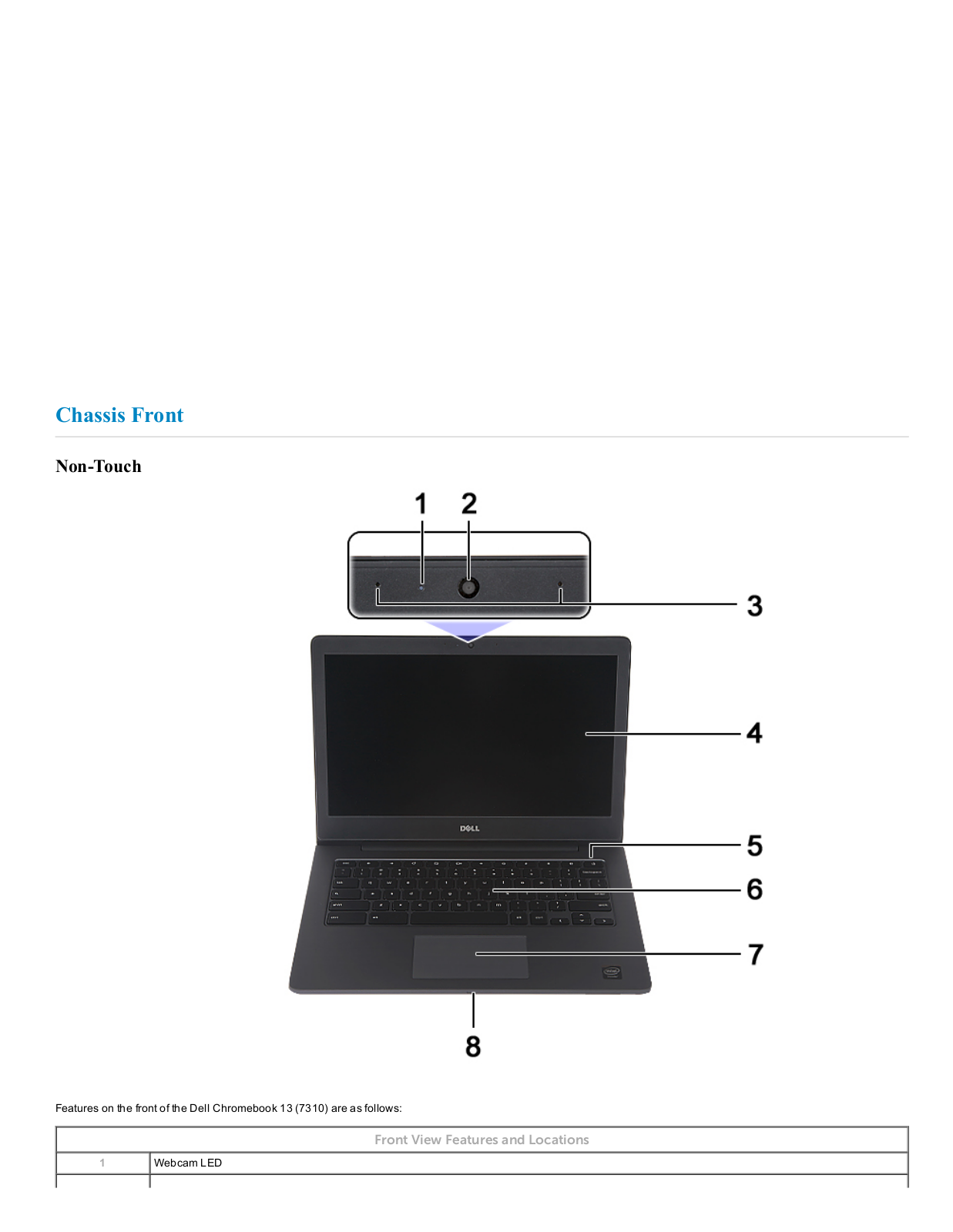
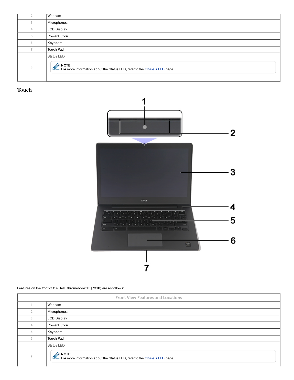
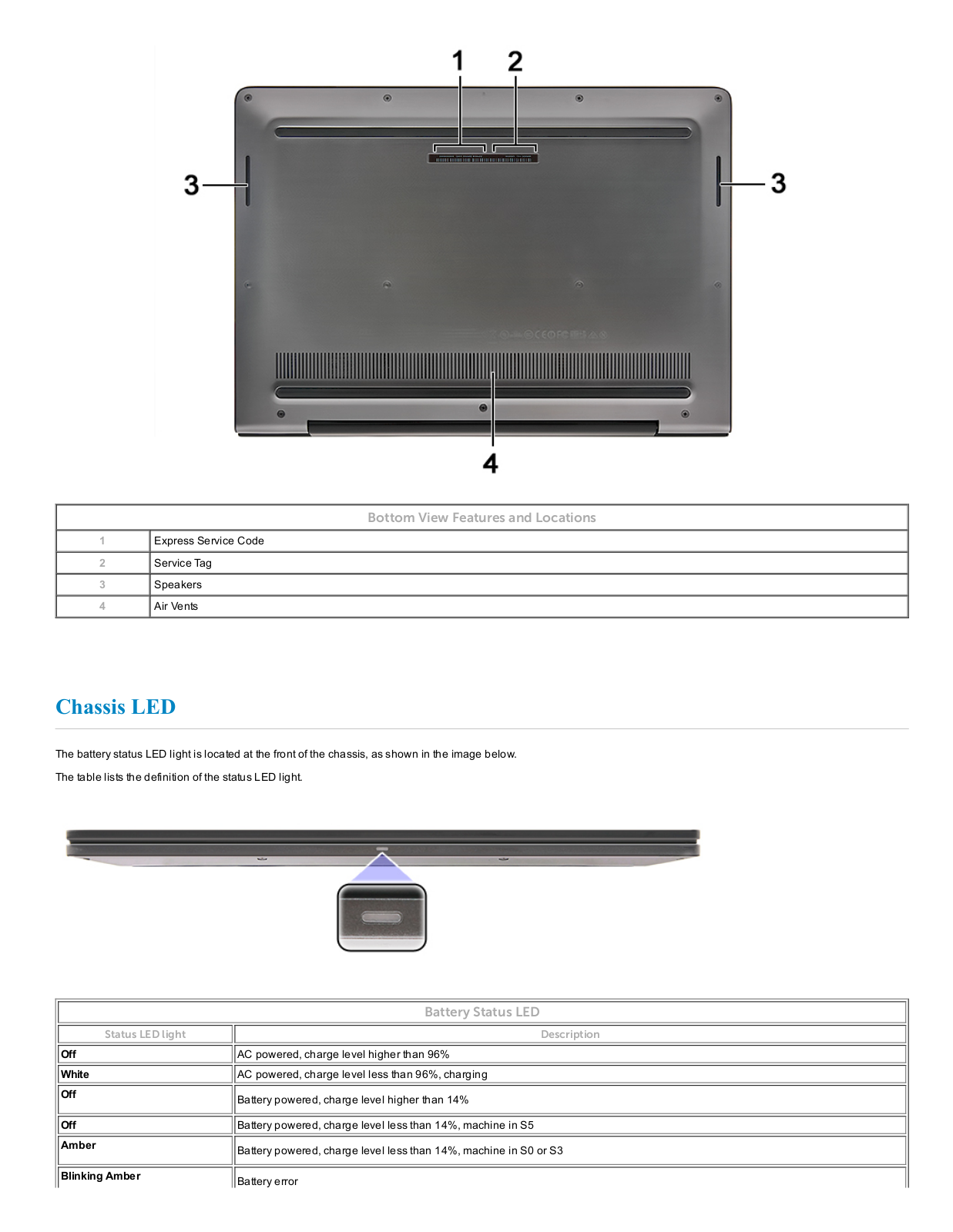
Chromebook 13-7310
Owners Manual
86 pgs
24.73 Mb
1
Service manual
7 pgs
391.64 Kb
0
Table of contents
Loading...
Dell Chromebook 13-7310 Owners Manual
...
Dell Owners Manual
Download
Specifications and Main Features
Frequently Asked Questions
User Manual
Download
Loading...
+
hidden pages
Unhide
You need points to download manuals.
1 point = 1 manual.
You can buy points or you can get point for every manual you upload.
Buy points
Upload your manuals
 Loading...