

Page 1

ChengMing 3967
Field Service Manual
Regulatory Model: D25M
Regulatory Type: D25M001
Page 2

Notes, cautions, and warnings
NOTE: A NOTE indicates important information that helps you make better use of your product.
CAUTION: A CAUTION indicates either potential damage to hardware or loss of data and tells you how to avoid the problem.
WARNING: A WARNING indicates a potential for property damage, personal injury, or death.
© 2016 Dell Inc. or its subsidiaries. All rights reserved. This product is protected by U.S. and international copyright and intellectual property laws. Dell and
the Dell logo are trademarks of Dell Inc. in the United States and/or other jurisdictions. All other marks and names mentioned herein may be trademarks of
their respective companies.
2016 - 12
Rev. A00
Page 3
Introduction
Welcome
The goal of this reference material is to provide field technicians with the information necessary to support the ChengMing 3967 systems
at customer locations and to prepare technical support agents to accurately and effectively resolve customer inquiries and technical
issues.
RTS Date: Worldwide — 12/15/2016
Department: Information Development
Author: Deepa S N
Contributing Sources: ChengMing Engineering/Extended team
1
Introduction 3
Page 4
System Information
Product Overview
ChengMing intends to bring best customer experience in China commercial Desktop marketing by integrating into China ecosystem.
ChengMing is the first generation system catering to the China and Hong Kong commercial base. It intends to generate incremental It
supports both Kabylake and Skylake processors. These systems leverages the Vostro segment's processor cost advantage.
Equipped with Chinese certifications to prove product quality and reliability. It supports local eClassroom software tailored for China’s
education market needs.
Technical Specifications
NOTE
: Offerings may vary by region. The following specifications are only those required by law to ship with your computer. For
more information about the configuration of your computer, go to Help and Support in your Windows operating system and
select the option to view information about your computer.
2
4 System Information
Page 5

System specifications
Feature Specification
Processor type
• Intel Celeron
• 6th Generation Intel Core i3/i5/i7
• Intel PDC
Total cache Up to 8 MB cache depending on processor type
Memory specifications
Feature Specification
Type Up to 2133 MHz
Connectors Two DDR4 UDIMM slots
Capacity 2 GB, 4 GB, 8 GB, and 16 GB
Minimum Memory 2 GB
Maximum Memory 32 GB
Video specifications
Feature —
ChengMing
3967
Specification
Video Controller Integrated
iGPU
Video Controller Discrete
nVIDIA GeForce GT 710
AMD Radeon™ R5 430
Video Memory independent card offering
Audio specifications
Feature
Specification
Controller ALC3234-CG (Realtek)
Speaker single 4-ohms, AVG speakers
Internal speaker
amplifier
Codec Build-in Class D
System Information 5
Page 6

Communication specifications
Feature Specification
Network adapter Realtek 10/100/1000 Mbps Ethernet LAN
Drives specifications
Feature Specification
Hard drive Two 2.5-inch SATA drive, one 3.5-inch SATA drive
Optical drive
(optional)
One DVD RW
Ports and connectors specifications
Feature Specification
Front port audio one universal audio jack
Front port USB 2.0 two
Front port USB 2.0 two
Rear port audio one audio line out
Rear port display one VGA, one HDMI
Rear port USB 2.0 two
Rear port USB 3.0 two
Rear port serial port one
Rear port PS/2 keyboard and mouse
Rear port RJ45 one
Power supply specifications
Feature
Specification
Type 290 W (UMA)
Frequency 47 Hz - 63 Hz
Voltage 90 VAC - 264 VAC
Input current 2.7 A / 5.4 A (290 W)
Physical Dimension
height
86.00 mm (3.38 inches)
Physical Dimension
weight
150.00 mm (5.90 inches)
6 System Information
Page 7

Feature Specification
Physical Dimension
height
140.00 mm (5.51 inches)
Coin cell battery 3 V CR2032 lithium coin cell
Physical dimension specifications
Feature Specification
Width 160 mm (6.29 inches)
Height 373.7 mm (14.7 inches)
Depth 289.4 mm (11.39 inches)
Weight 6.5 kg (14.33 lbs)
Controls and lights specifications
Feature Specification
Power button light White light — Solid white light indicates power-on state; blinking white light indicates sleep state of the computer.
Hard Drive activity
light
White light — Blinking white light indicates that the computer is reading data from or writing data to the hard
drive.
Back panel:
Link integrity light on
integrated network
adapter :
Green — a good 10 Mbps connection exists between the network and the computer.
Orange — a good 1000 Mbps connection exists between the network and the computer.
Off (no light) — the computer is not detecting a physical connection to the network.
Network activity
light on integrated
network adapter
Yellow light — A blinking yellow light indicates that network activity is present.
Power supply
diagnostic light
Green light — The power supply is turned on and is functional. The power cable must be connected to the power
connector (at the back of the computer) and the electrical outlet.
Environmental specifications
Temperature
Specifications
Operating 0°C to 35°C (32°F to 95°F)
Storage –40°C to 65°C (–40°F to 149°F)
Relative humidity
(maximum)
Specifications
Operating 10 % to 90 % (non condensing)
Storage 5 % to 95 % (non condensing)
System Information 7
Page 8

Maximum
vibration:
Specifications
Operating 0.66 GRMS
Storage 1.30 GRMS
Maximum shock: Specifications
Operating 110 G
Storage 160 G
Altitude
(maximum)
Specifications
Operating –15.2 m to 3048 m (–50 to 10,000 ft)
Storage –15.20 m to 10,668 m (–50 ft to 35,000 ft)
Airborne
contaminant level
G2 or lower as defined by ANSI/ISA-S71.04-1985
Critical callouts
Processor / Graphics configurations
The following table indicates the different processor/graphics configurations for ChengMing 3967.
Table 1. Processor / Graphics configurations
Processor / Graphics ChengMing 3967
CPU (Skylake) Intel Celeron, Pentium, or Core i3 / i5 / i7
1 GB Discrete Graphics OLGA 1GB
2 GB Discrete Graphics Nvidia GT710 Graphics Card
Other Graphics None
Hard drive / Optical drive configurations
The system board for ChengMing 3967 features three SATA connectors for storage devices, while the chassis for ChengMing 3967
features slots for one 3.5” hard drive, two 2.5” hard drives and one optical drive. Under these conditions the following SATA-based
storage device configurations are available for ChengMing 3967.
Table 2. Hard drive / Optical drive configurations
SATA Connections Configuration
1 3.5” HDD0
2 Optical drive + 3.5” HDD0
2 3.5” HDD0 + 2.5” HDD1
3 Optical drive + 3.5” HDD0 + 2.5” HDD1
3 3.5” HDD0 + 2.5” HDD1 + 2.5” HDD2
8 System Information
Page 9
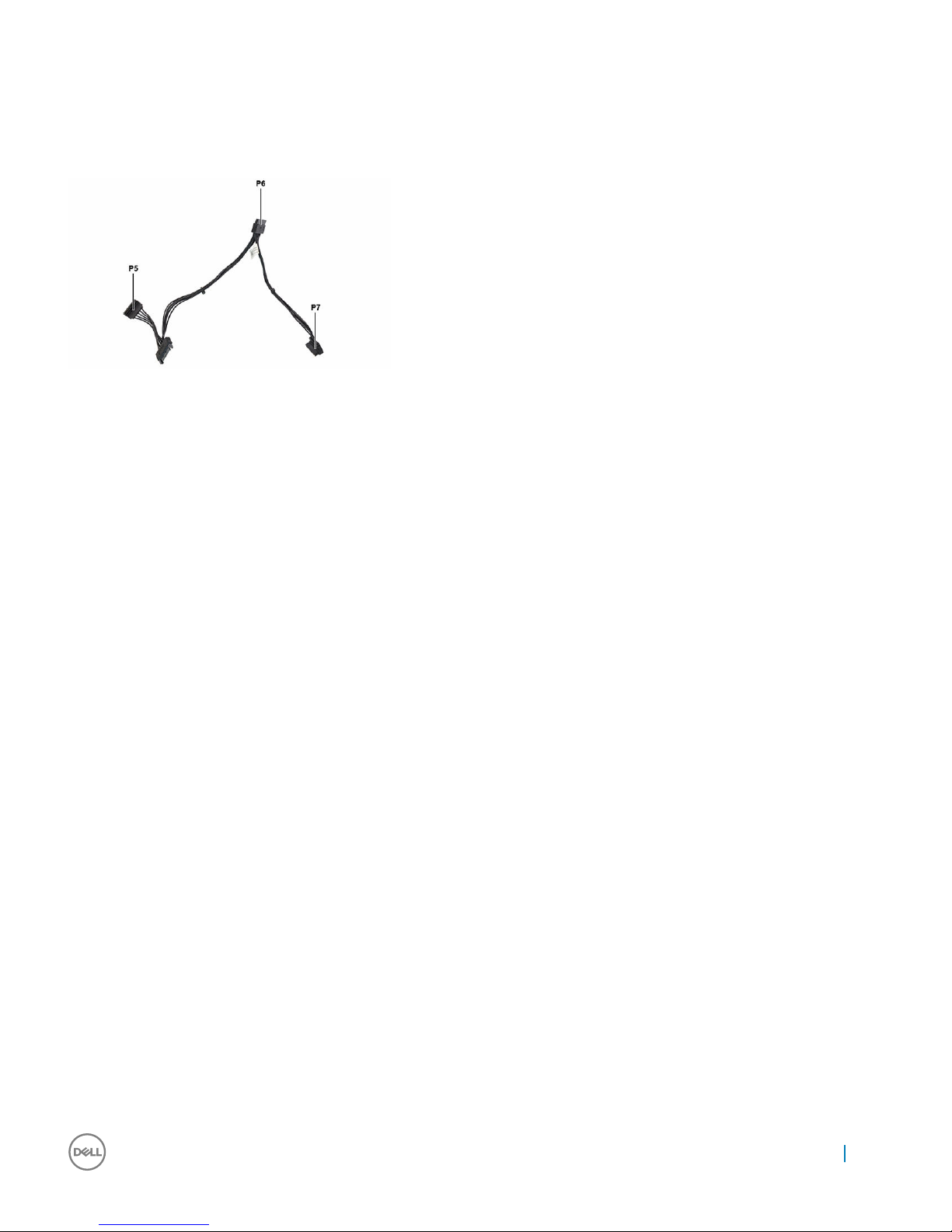
Hard drive power extension cable
Any additional hard drive configurations require the use of a 1-to-3 hard drive power extension cable.
Hard drive replacement
When replacing the hard drives for ChenMing 3967, the user must hold the hard drive securely while removing or securing the screws to
ensure that the hard drives do not fall and cause damage to either the system or the hard drive, as seen in the images below.
System Information
9
Page 10
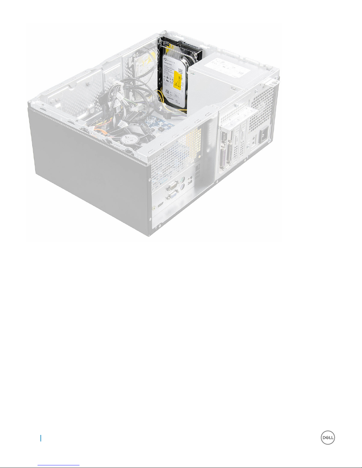
Figure 1. 3.5 inch hard drive
10
System Information
Page 11
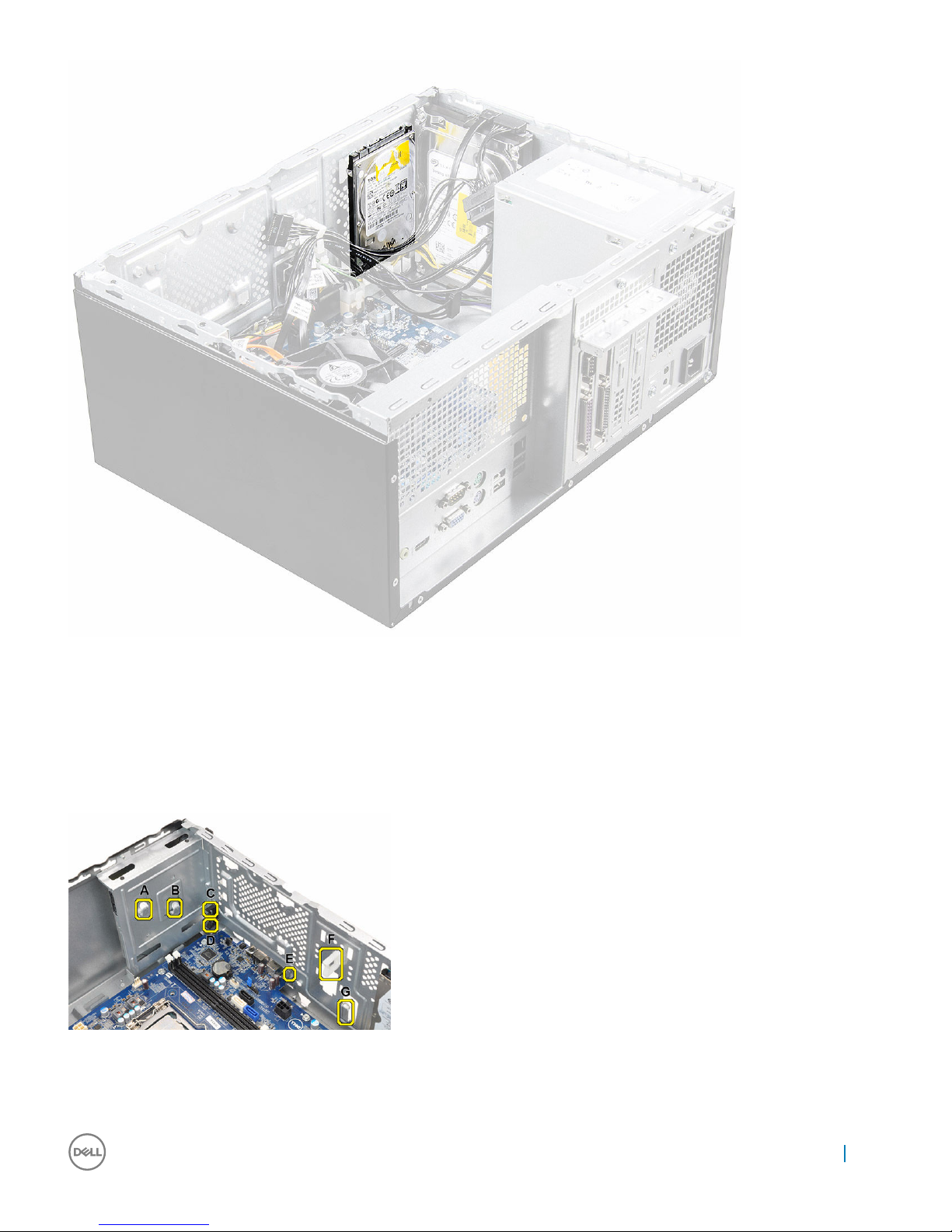
Figure 2. 2.5 inch hard drive
Cable routing
The chassis for ChengMing 3967 features seven hooks/clips used to route the various data and power cables within the system. The
image and table below indicates which hook/clip the cables are routed through.
Figure 3. Cable routing
System Information
11
Page 12

Table 3. Cable routing
Cable Routing Path
3.5” HDD0 SATA Data Cable HDD0 → Cable Clip F → System Board
3.5” HDD0 P3 Power Cable (For models with only one hard
drive installed)
HDD0 → Cable Clip F → System Board
2.5” HDD1 SATA Data Cable HDD1 → Cable Clip F → System Board
2.5” HDD1 P7 Power Cable HDD1 → Cable Clip F → System Board
2.5” HDD2 SATA Data Cable (optional) HDD2 → Cable Clip F → System Board
2.5” HDD2 P6 Power Cable (optional) HDD2 → Cable Clip F → System Board
ODD SATA Data Cable ODD → Cable Hook A → Cable Clip C → System Board
ODD P4 Power Cable ODD → Cable Hook A → Cable Clip C → System Board
8-Pin Power Cable PSU → Cable Hook G → System Board
4-Pin Power Cable PSU → Cable Hook E → Cable Clip D → Cable Hook B → System Board
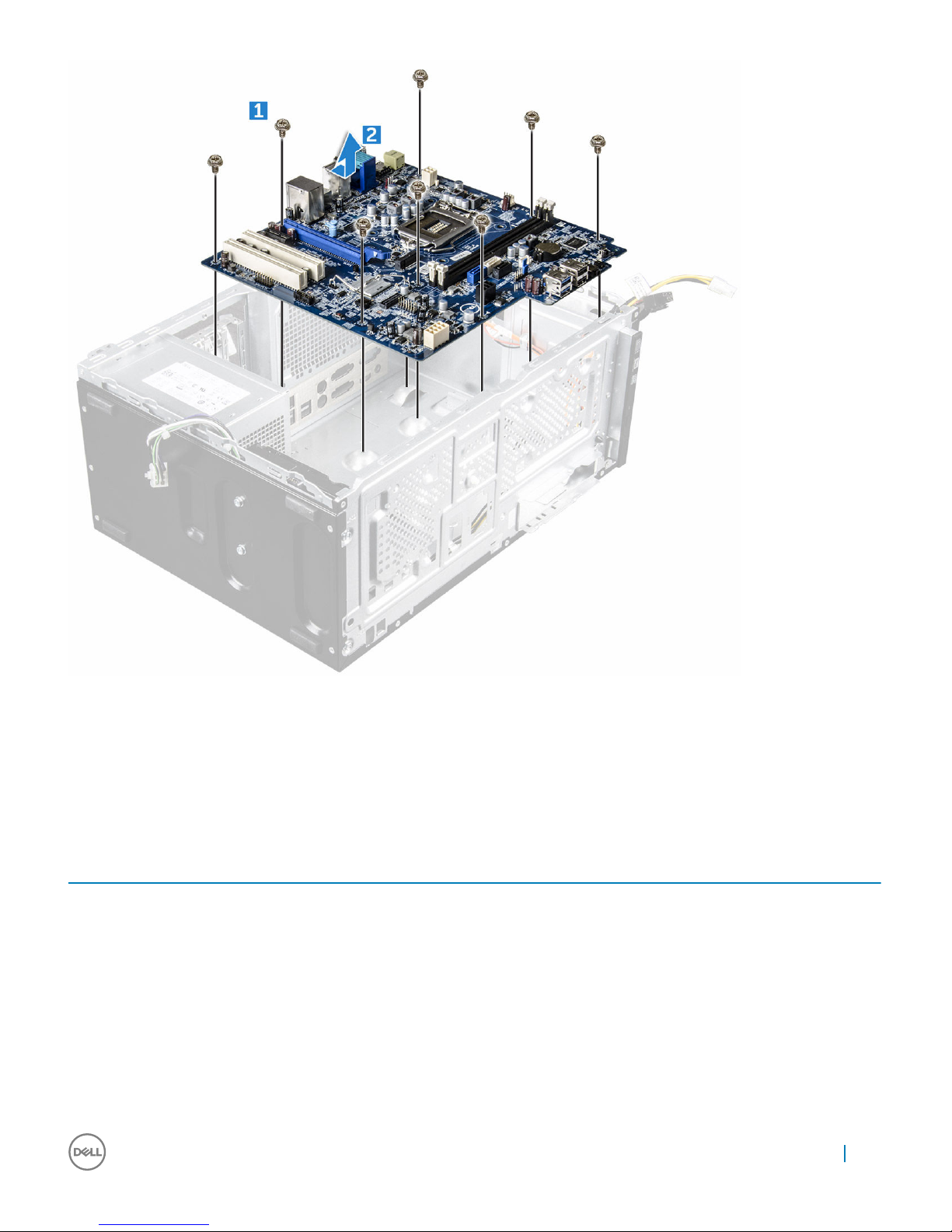
System board removal
When removing the system board for ChengMing 3967 from the system chassis the system board must be carefully pushed towards the
front IO port slots then carefully lifted up from the rear side, as indicated in the images below.
12
System Information
Page 13
Customer replaceable units (CRU) and Field
replaceable units (FRU) list
The following table shows CRU and FRU list:
Table 4. CRU/FRU List
Component CRU FRU
Slide Cover Yes No
Front Bezel Yes No
Memory module Yes No
Heat sink fan No Yes
3.5 Hard drive Yes No
2.5 Hard drive Yes No
Optical drive Yes No
Power combo cable No Yes
ODD SATA cable No Yes
System Information 13
Page 14

Component CRU FRU
3.5 HDD SATA cable No Yes
2.5 HDD SATA cable No Yes
Expansion card Yes No
WLAN card Yes No
Coin cell battery Yes No
Power supply Yes No
System board No Yes
Speaker Yes No
14 System Information
Page 15
Chassis
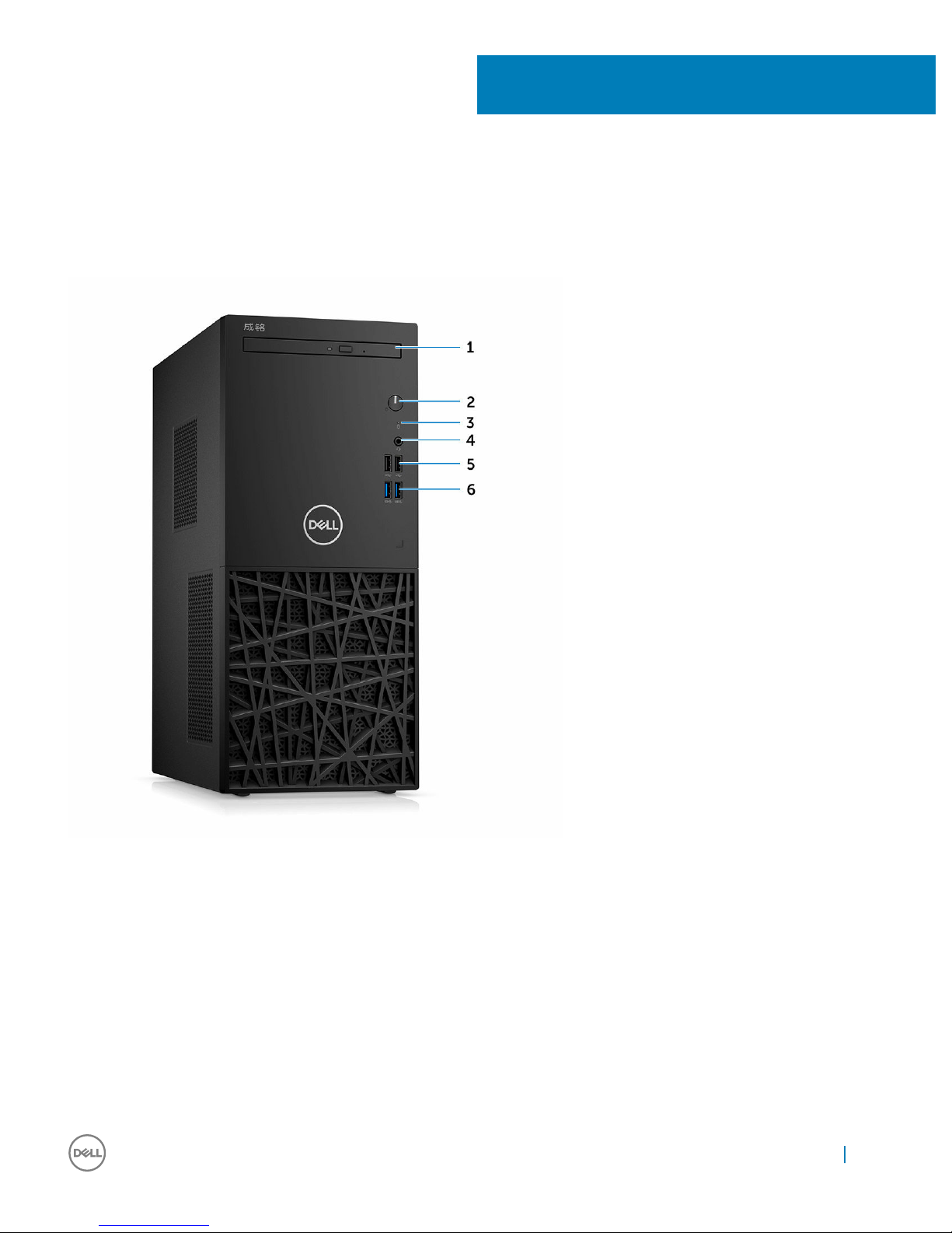
System front view
1 Optical drive 2 Power button and power status light
3 Hard drive activity light 4 Universal audio jack
5 USB 2.0 ports 6 USB 3.0 ports
3
Chassis 15
Page 16
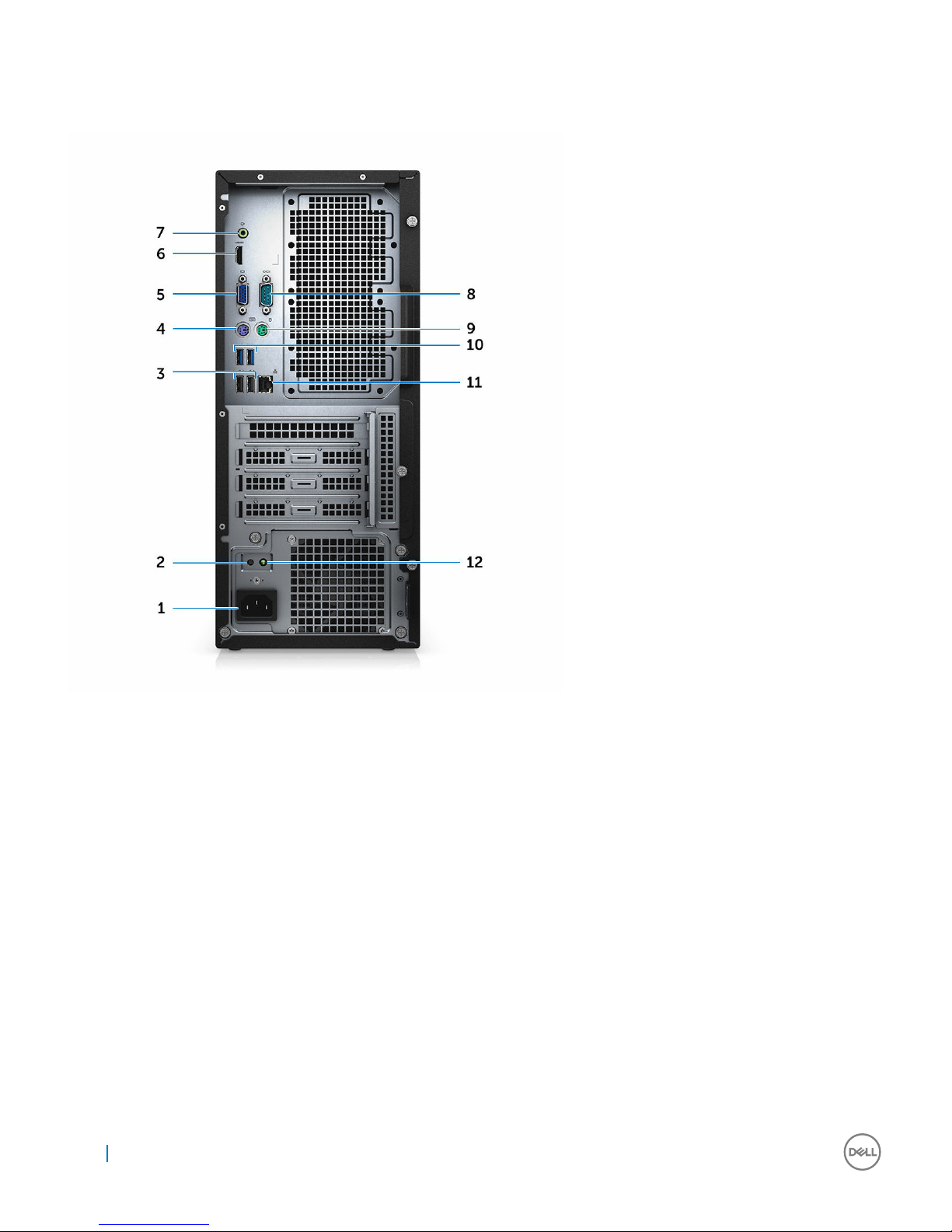
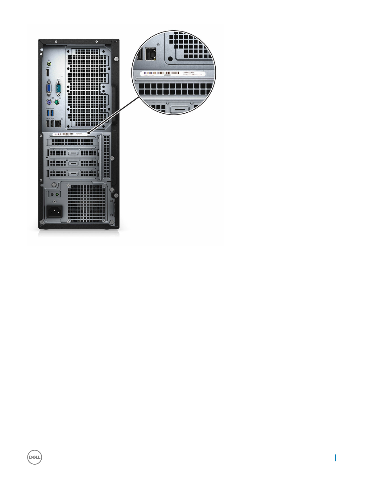
System back view
1 Power connector port 2 Power supply diagnostic button
3 USB 2.0 port with USB wake support 4 PS2 port for keyboard
5 VGA port 6 HDMI port
7 Line out port 8 Serial port
9 PS2 port for mouse 10 USB 3.0 ports (2)
11 Network port 12 Power diagnostic light
Service tag location
The Service Tag and Express Service Code for ChenMing3967 is located at the back of the computer.
16
Chassis
Page 17
Chassis 17
Page 18
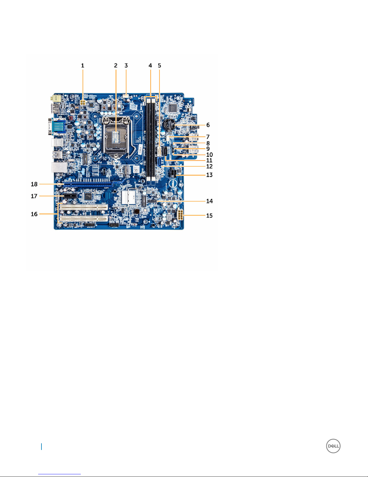
System board layout
The following image displays the system board layout of the computer.
1 CPU Power Connector (ATX_CPU) 2 Processor Socket (CPU)
3 CPU Fan Connector (FAN_CPU) 4 Memory Connectors (DIMM1/DIMM2)
5 SATA 1 connector (White color) 6 Battery Connector (BATTERY)
7 Internal Speaker Connector (INT_SPKR) 8 Password Clear Jumper (P1)
9 Service Mode Jumper (P3) 10 CMOS Clear Jumper (P2)
11 SATA 2 connector (Black color) 12 SATA 0 connector (Blue color)
13 HDD_ODD_PowerCable Connector (SATA_PWR) 14 Internal USB connector (WF_BT_USB)
15 ATX Power Connector (ATX_SYS) 16 PCI Connector (SLOT3 and SLOT4)
17 PCI-e X1 Connector (SLOT2) 18 PCI-e X16 Connector (SLOT1)
18 Chassis
Page 19

Field Service Information
Working on your computer
Safety Precautions
The safety precautions chapter details the primary steps to be taken before performing any disassembly instructions.
Observe the following safety precautions before you perform any installation or break/fix procedures involving disassembly or reassembly:
• Turn off the system and all attached peripherals
• Disconnect the system and all attached peripherals from AC power, and then remove the battery
• Disconnect all network cables, telephone or telecommunications lines from the system
• Use a wrist grounding strap and mat when working inside any computer system to avoid electrostatic discharge (ESD) damage.
• After removing any system component, carefully place the removed component on an anti-static mat
• Wear shoes with nonconductive rubber soles to help reduce the chance of being shocked or seriously injured in an electrical accident
Standby power
Dell products with standby power must be completely unplugged before you open the case. Systems that incorporate standby power are
essentially powered while turned off. The internal power enables the system to be remotely turned on (wake on LAN) and suspended into
a sleep mode, and has other advanced power management features.
After unplugging the system and before removing components, wait approximately 30 to 45 seconds to allow the charge to drain from the
circuits. Remove the battery from portable computers.
Bonding
Bonding is a method for connecting two or more grounding conductors to the same electrical potential. This is done through the use of a
Field Service Electrostatic discharge (ESD) kit. When connecting a bonding wire, always ensure that it is connected to bare metal and
never to a painted or non-metal surface. The wrist strap should be secure and in full contact with your skin, and be sure to always remove
all jewelry such as watches, bracelets, or rings prior to bonding yourself and the equipment
Electrostatic discharge (ESD) protection
ESD is a major concern when you handle electronic components, especially sensitive components such as expansion cards, processors,
memory DIMMs, and system boards. Very slight charges can damage circuits in ways that may not be obvious, such as intermittent
problems or a shortened product life span. As the industry pushes for lower power requirements and increased density, ESD protection is
an increasing concern.
Due to the increased density of semiconductors used in recent Dell products, the sensitivity to static damage is now higher than in
previous Dell products. For this reason some previously approved methods of handling parts are no longer applicable.
Two recognized types of ESD damage are catastrophic and intermittent failures.
• Catastrophic – Catastrophic failures represent approximately 20 percent of ESD-related failures. The damage causes an immediate
and complete loss of device functionality. An example of catastrophic failure is a memory DIMM that has received a static shock and
immediately generates a "No POST/No Video" symptom with a beep code emitted for missing or nonfunctional memory
4
Field Service Information 19
Page 20

• Intermittent – Intermittent failures represent approximately 80 percent of ESD-related failures. The high rate of intermittent failures
means that most of the time when damage occurs, it is not immediately recognizable. The DIMM receives a static shock, but the
tracing is merely weakened and does not immediately produce outward symptoms related to the damage. The weakened trace may
take weeks or months to melt, and in the meantime may cause degradation of memory integrity, intermittent memory errors, etc.
The more difficult type of damage to recognize and troubleshoot is the intermittent (also called latent or "walking wounded") failure. The
following image shows an example of intermittent damage to a memory DIMM trace. Although the damage is done, the symptoms may not
become an issue or cause permanent failure symptoms for some time after the damage occurs.
Perform the following steps to prevent ESD damage:
• Use a wired ESD wrist strap that is properly grounded. The use of wireless anti-static straps in no longer allowed; they do not provide
adequate protection. Touching the chassis before handling parts does not ensure adequate ESD protection on parts with increased
sensitivity to ESD damage.
• Handle all static-sensitive components in a static-safe area. If possible, use anti-static floor pads and workbench pads.
• Handle all static-sensitive components in a static-safe area. If possible, use anti-static floor pads and workbench pads.
• When unpacking a static-sensitive component from its shipping carton, do not remove the component from the anti-static packing
material until you are ready to install the component. Before unwrapping the anti-static packaging, be sure to discharge static
electricity from your body.
• Before transporting a static-sensitive component, place it in an anti-static container or packaging.
ESD field service kit
The unmonitored Field Service kit is the most commonly used. Each Field Service kit includes three main components: anti-static mat,
wrist strap, and bonding wire.
Components of an ESD field service kit
The components of ESD field service kit are:
• Anti-Static Mat – The anti-static mat is dissipative and should be used to safely place parts on during service procedures. When using
an anti-static mat, your wrist strap should be snug and the bonding wire should be connected to the mat and to bare-metal on the
system being worked on. Once deployed properly, service parts can be removed from the ESD bag and placed directly on the mat.
Remember, the only safe place for ESD-sensitive items are in your hand, on the ESD mat, in the system, or inside a bag.
• Wrist Strap and Bonding Wire – The wrist strap and bonding wire can be either directly connected between your wrist and bare
metal on the hardware if the ESD mat is not required, or connected to the anti-static mat to protect hardware that is temporarily
placed on the mat. The physical connection of the wrist strap and bonding wire between your skin, the ESD mat, and the hardware is
known as bonding. Use only Field Service kits with a wrist strap, mat, and bonding wire. Never use wireless wrist straps. Always be
aware that the internal wires of a wrist strap are prone to damage from normal wear and tear, and must be checked regularly with a
wrist strap tester in order to avoid accidental ESD hardware damage. It is recommended to test the wrist strap and bonding wire a
minimum of once per week.
• ESD Wrist Strap Tester – The wires inside of an ESD strap are prone to damage over time. When using an unmonitored kit, it is best
practice to regularly test the strap prior to each service call, and at a minimum, test once per week. A wrist strap tester is the best
method for doing this test. If you do not have your own wrist strap tester, check with your regional office to find out if they have one.
To perform the test, plug the wrist-strap's bonding-wire into the tester while it is strapped to your wrist and push the button to test. A
green LED is lit if the test is successful; a red LED is lit and an alarm sounds if the test fails
• Insulator Elements – It is critical to keep ESD sensitive devices, such as plastic heat sink casings, away from internal parts that are
insulators and often highly charged.
• Working Environment – Before deploying the ESD Field Service kit, assess the situation at the customer location. For example,
deploying the kit for a server environment is different than for a desktop or portable environment. Servers are typically installed in a
rack within a data center; desktops or portables are typically placed on office desks or cubicles. lways look for a large open flat work
area that is free of clutter and large enough to deploy the ESD kit with additional space to accommodate the type of system that is
being repaired. The workspace should also be free of insulators that can cause an ESD event. On the work area, insulators such as
Styrofoam and other plastics should always be moved at least 12 inches or 30 centimeters away from sensitive parts before physically
handling any hardware components
• ESD Packaging – All ESD-sensitive devices must be shipped and received in static-safe packaging. Metal, static-shielded bags are
preferred. However, you should always return the damaged part using the same ESD bag and packaging that the new part arrived in.
The ESD bag should be folded over and taped shut and all the same foam packing material should be used in the original box that the
new part arrived in. ESD-sensitive devices should be removed from packaging only at an ESD-protected work surface, and parts
should never be placed on top of the ESD bag because only the inside of the bag is shielded. Always place parts in your hand, on the
ESD mat, in the system, or inside an anti-static bag.
20
Field Service Information
Page 21

• Transporting Sensitive Components – When transporting ESD sensitive components such as replacement parts or parts to be
returned to Dell, it is critical to place these parts in anti-static bags for safe transport.
ESD protection summary
It is strongly suggested that all field service technicians use the traditional wired ESD grounding wrist strap and protective anti-static mat
at all times when servicing Dell products. In addition, it is critical that technicians keep sensitive parts separate from all insulator parts while
performing service and that they use anti-static bags for transporting sensitive components.
Transporting sensitive components
When transporting ESD sensitive components such as replacement parts or parts to be returned to Dell, it is critical to place these parts in
anti-static bags for safe transport.
Lifting Equipment
Adhere to the following guidelines when lifting equipment:
CAUTION: :
Do not lift greater than 50 pounds. Always obtain assistance from another person or persons, or use a mechanical lifting device.
1 a Get a firm balanced footing. Keep your feet apart for a stable base, and point your toes out.
b Bend your knees. Do not bend at the waist.
c Tighten stomach muscles. Abdominal muscles support your spine when you lift, offsetting the force of the load.
d Lift with your legs, not your back.
e Keep the load close. The closer it is to your spine, the less force it exerts on your back.
f Keep your back upright, whether lifting or setting down the load. Do not add the weight of your body to the load. Avoid twisting
your body and back.
g Follow the same techniques in reverse to set the load down.
Before working inside your computer
To avoid damaging your computer, perform the following steps before you begin working inside the computer.
1 Ensure that you follow the Safety instructions.
2 Ensure that your work surface is flat and clean to prevent the computer cover from being scratched.
3 Turn off your computer, see Turning off your computer.
CAUTION
: To disconnect a network cable, first unplug the cable from your computer and then unplug the cable from
the network device.
4 Disconnect all the network cables from the computer.
5 Disconnect your computer and all attached devices from the electrical outlets.
6 Press and hold the power button while the computer is unplugged to ground the system board.
7 Remove the cover.
CAUTION
: Before touching anything inside your computer, ground yourself by touching an unpainted metal surface,
such as the metal at the back of the computer. While you work, periodically touch an unpainted metal surface to
dissipate static electricity, which could harm internal components.
CAUTION: Make sure that you place the cooler outlet side of your system at least 5 cm away from wall to prevent
system overheat.
CAUTION: Your system cannot be placed crosswise and make sure that there is no equipment on the side cover.
Field Service Information 21
Page 22

Safety instructions
Use the following safety guidelines to help protect your computer from potential damage and to help to ensure your personal safety.
Unless otherwise noted, each procedure included in this document assumes that the following conditions exist:
• You have read the safety information that shipped with your computer.
• A component can be replaced or--if purchased separately--installed by performing the removal procedure in reverse order.
WARNING: Disconnect all power sources before opening the computer cover or panels. After you finish working inside the
computer, replace all covers, panels, and screws before connecting to the power source.
WARNING: Before working inside your computer, read the safety information that shipped with your computer. For additional
safety best practices information, see the Regulatory Compliance Homepage at www.Dell.com/regulatory_compliance
CAUTION: Many repairs may only be done by a certified service technician. You should only perform troubleshooting and simple
repairs as authorized in your product documentation, or as directed by the online or telephone service and support team.
Damage due to servicing that is not authorized by Dell is not covered by your warranty. Read and follow the safety instructions
that came with the product.
CAUTION: To avoid electrostatic discharge, ground yourself by using a wrist grounding strap or by periodically touching an
unpainted metal surface, such as a connector on the back of the computer.
CAUTION: Handle components and cards with care. Do not touch the components or contacts on a card. Hold a card by its
edges or by its metal mounting bracket. Hold a component such as a processor by its edges, not by its pins.
CAUTION: When you disconnect a cable, pull on its connector or on its pull-tab, not on the cable itself. Some cables have
connectors with locking tabs; if you are disconnecting this type of cable, press in on the locking tabs before you disconnect the
cable. As you pull connectors apart, keep them evenly aligned to avoid bending any connector pins. Also, before you connect a
cable, ensure that both connectors are correctly oriented and aligned.
NOTE: The color of your computer and certain components may appear differently than shown in this document.
Turning off your computer — Windows 10
CAUTION
: To avoid losing data, save and close all open files and exit all open programs before you turn off your computer.
1 Click or tap .
2 Click or tap and then click or tap Shut down.
NOTE
: Ensure that the computer and all attached devices are turned off. If your computer and attached devices did
not automatically turn off when you shut down your operating system, press and hold the power button for about 6
seconds to turn them off.
After working inside your computer
After you complete any replacement procedure, ensure that you connect any external devices, cards, and cables before turning on your
computer.
1 Replace the cover.
CAUTION
: To connect a network cable, first plug the cable into the network device and then plug it into the computer.
2 Connect any telephone or network cables to your computer.
3 Connect your computer and all attached devices to their electrical outlets.
4 Turn on your computer.
22
Field Service Information
Page 23

5 If required, verify that the computer works correctly by running Dell Diagnostics.
Recommended tools
The procedures in this document require the following tools:
• Small flat blade screwdriver
• Phillips # 1 screwdriver
• Small plastic scribe
• Hex screwdriver
Screw size list
Table 5. ChenMing 3967 screw size list
Component
M2L2(04)
6-32xL3.6 M3xL3.5 6-32xL6.35
System board 8
PSU 4
Front I/O bracket screw 1
2.5" Hard drive screw 2
3.5" Hard drive screw 4
Optical drive screw 2
Side cover screw 2
PCI cover screw 1
Removing and installing components
This section provides detailed information on how to remove or install the components from your computer.
Cover
Removing the cover
1 Follow the procedure in Before working inside your computer.
2 To remove the cover:
a Remove the screws that secure the cover to the computer [1].
b Slide and lift the cover to remove it from the computer [2].
Field Service Information
23
Page 24

Installing the cover
1 Place the cover on the computer.
2 Slide the computer cover towards the front of the chassis until it is fully engaged.
3 Tighten the screw in clockwise direction to secure the computer cover.
4 Follow the procedure in After working inside your computer.
Front Bezel
Removing the front bezel
1 Follow the procedure in Before working inside your computer.
2 Remove the cover.
3 To remove the front bezel:
a Pry the front bezel retention clips away from the chassis. [1].
b Rotate the bezel away from the computer to release the hooks on the opposite edge of the bezel from the chassis. Then, lift
the chassis and remove the front bezel from the computer. [2].
24
Field Service Information
Page 25

Installing the front bezel
1 Insert the hooks along the bottom edge of the front bezel into the slots on the chassis front.
2 Push the bezel toward the computer to engage the front bezel retention clips until they click into place.
3 Install the cover.
4 Follow the procedure in After working inside your computer.
Hard drive
Removing the 3.5 inch hard drive
1 Follow the procedure in Before working inside your computer.
2 Remove the:
a cover
b front bezel
3 To remove the 3.5 inch hard drive:
a Disconnect the data cable and the power cable from the hard drive [1].
b Remove the screws (6-32xL3.6) that secure the hard drive to the computer [2, 3].
c Slide and life the hard drive away from the computer [4].
Field Service Information
25
Page 26

Installing the 3.5 inch hard drive
1 Insert the 3.5 inch hard drive into the slot on the computer.
2 Tighten the screws(6-32xL3.6) to secure the hard drive to the computer.
3 Connect the hard drive and power cable to the hard drive.
4 Install the:
a front bezel
b cover
5 Follow the procedure in After working inside your computer.
Removing the 2.5 inch hard drive
1 Follow the procedure in Before working inside your computer.
2 Remove the:
a cover
b front bezel
3 To remove the 2.5 inch hard drive:
a Disconnect the data cable and the power cable from the hard drive [1].
b Remove the screws (M3L3.5) that secure the hard drive to the computer [2].
c Slide and life the hard drive away from the computer [3].
26
Field Service Information
Page 27

Installing the 2.5 inch hard drive
1 Insert the 2.5 inch hard drive into the slot on the computer.
2 Tighten the screws(M3L3.5) to secure the hard drive to the computer.
3 Connect the hard drive and power cable to the hard drive.
4 Install the:
a front bezel
b cover
5 Follow the procedure in After working inside your computer.
Optical drive
Removing the optical drive
1 Follow the procedure in Before working inside your computer.
2 Remove the:
a cover
b front bezel
3 To remove the optical drive:
Field Service Information
27
Page 28

a Disconnect the data cable and the power cable from the optical drive [1].
b Remove the screws (M2L2(04)) that secure the optical drive to the computer [2].
c Pull the optical drive out of the computer [3]..
Installing the optical drive
1 Insert the optical drive into the slot on the computer.
2 Tighten the screws(M2L2Ø4)) to secure the optical drive o the computer.
3 Connect the optical drive and power cable to the optical drive.
4 Install the:
a front bezel
b cover
5 Follow the procedure in After working inside your computer.
Cooling shroud
Removing the cooling shroud
1 Follow the procedure in Before working inside your computer.
2 Remove the:
28
Field Service Information
Page 29

a cover
b front bezel
3 To remove the cooling shroud:
a Hold the touch points and pry the edges [1, 2].
b Lift the cooling shroud away from the computer [3].
Installing the cooling shroud
1 Align the tabs on the cooling shroud with the securing slots on the computer.
2 Lower the cooling shroud into the chassis until it is firmly seated.
3 Install the:
a front bezel
b cover
4 Follow the procedure in After working inside your computer.
Field Service Information
29
Page 30

Power supply unit
Removing the power supply unit (PSU)
1 Follow the procedure in Before working inside your computer.
2 Remove the:
a cover
b front bezel
c cooling shroud
3 To disconnect the cables:
a Press the tab of the 4-pin power cables and disconnect it from the system board [1].
b Release the cables from the clip [2].
c Press the tab of the 8-pin power cables and disconnect it from the system board [1].
4 To remove the power supply unit (PSU):
a Remove the screws (6-32xL6.35) that secure the PSU to the computer [1].
b Slide and lift the PSU from the computer [2].
30
Field Service Information
Page 31

Installing the power supply unit (PSU)
1 Place the power supply in the chassis and slide towards the back of the system to secure it.
2 Tighten the screws (6-32xL6.35) at the back of the computer to secure power supply.
3 Connect the 8-pin power cable to the system board.
4 Thread the power cables through the chassis clip.
5 Connect the 4-pin power cable to the system board.
6 Install the:
a cooling shroud
b front bezel
c cover
7 Follow the procedure in After working inside your computer.
Speaker
Removing the speaker
1 Follow the procedure in Before working inside your computer.
2 Remove the:
a cover
b front bezel
3 To remove the speaker:
a Disconnect the speaker cable from system board [1].
Field Service Information
31
Page 32

b Press the securing tab on the speaker and remove the speaker from the chassis [2, 3].
Installing the speaker
1 Slide the speaker module into the slot.
2 Connect the speaker cable to the system board.
3 Install the:
a front bezel
b cover
4 Follow the procedure in After working inside your computer.
Heat sink
Removing the heat sink assembly
1 Follow the procedure in Before working inside your computer.
2 Remove the:
a cover
32
Field Service Information
Page 33

b cooling shroud
3 To remove the heat sink assembly:
a Disconnect the heat sink cable from the system board [1].
b Loosen the captive screws(6-32xL6.35) in diagonal order [2].
NOTE: Remove the screws that secure the heat sink to the system board in the order of the callouts shown
[1, 2, 3, 4].
c Lift the heat sink assembly away from the computer [3].
Installing the heat sink assembly
1 Align the heat sink assembly with screw holders on the system board.
2 Tighten the screws(6-32xL6.35) to secure the heat sink assembly to the computer and system board.
NOTE
: Tighten the screws on the system board in the order of the callout numbers [1, 2, 3, 4].
3 Connect the heat sink cable to the connector on the system board.
4 Install the:
a cooling shroud
b cover
5 Follow the procedure in After working inside your computer.
Field Service Information
33
Page 34

Memory module
Removing the memory module
1 Follow the procedure in Before working inside your computer.
2 Remove the cover.
3 To remove the memory module:
a Pull the clips securing the memory module until the memory module pops up.
b Remove the memory module from the system board.
Installing the memory module
1 Insert the memory module into the memory module socket until the clips secure the memory module.
2 Install the cover.
3 Follow the procedure in After working inside your computer.
Expansion card
Removing the expansion card
1 Follow the procedure in Before working inside your computer.
2 Remove the cover.
3 To remove the expansion card:
a Remove the screw (6-32xL6.35) that secures the metal card-retension latch to the computer [1].
b Pull the metal card-retension latch downward [2].
c Push the release tab and lift the expansion card from the system board [3].
34
Field Service Information
Page 35

Installing the expansion card
1 Insert the expansion card in the connector on the system board and press down until secured.
2 Push the metal card-retention latch back to its position.
3 Tighten the screw (6-32xL6.35) that secures the metal card-retention latch to the computer.
4 Install the cover.
5 Follow the procedure in After working inside your computer.
Coin cell battery
Removing the coin cell battery
1 Follow the procedure in Before working inside your computer.
2 Remove the cover.
3 To remove the coin cell battery:
a Press the release latch away from the battery to allow the battery to pop-up from the socket.
b Lift the coin-cell battery out of the computer.
Field Service Information
35
Page 36

Installing the coin cell battery
1 Place the coin cell battery in its slot on the system board.
2 Press until the release latch springs back into place and secures it.
3 Install the cover.
4 Follow the procedure in After working inside your computer.
Processor
Removing the processor
1 Follow the procedure in Before working inside your computer.
2 Remove the:
a cover
b cooling shroud
c heat sink
3 To remove the processor:
a Press the release lever down and then move it outward to release it from the retention hook [1].
CAUTION
: The processor socket pins are fragile and can be permanently damaged. Be careful not to bend
the pins in the processor socket when removing the processor out of the socket.
b Lift the processor cover and remove the processor from the socket. Place it in an antistatic bag [2, 3].
Installing the processor
1 Insert the processor in the processor socket. Ensure the processor is properly seated.
CAUTION
: Do not use force to seat the processor. When the processor is positioned correctly, it engages easily into
the socket.
2 Lower the processor cover.
3 Press the release lever down and then move it inward to secure it with the retention hook.
36
Field Service Information
Page 37

4 Install the:
a heat sink
b cooling shroud
c cover
5 Follow the procedure in After working inside your computer.
System board
Removing the system board
1 Follow the procedure in Before working inside your computer.
2 Remove the:
a cover
b front bezel
c 3.5 inch hard drive
d 2.5 inch hard drive
e optical drive
f cooling shroud
g power supply unit
h speaker
i heat sink
j memory module
k expansion card
l coin cell battery
m processor
3 To remove I/O panel cover:
a Remove the screw (6-32xL6.35) that secures the I/O panel cover to the computer [1].
b Slide the I/O panel cover [2].
Field Service Information
37
Page 38

4 Disconnect the hard drive power cable, optical drive power cable, speaker cable, power supply unit cable [1, 2, 3].
38
Field Service Information
Page 39

5 To remove the system board:
a Remove the screws (6-32xL6.35) that secure the system board to the computer [1].
b Tilt the system board at 45–degrees, and then lift the system board out of the computer [2].
Field Service Information
39
Page 40

Installing the system board
1 Align the system board to the port connectors on the rear of the chassis and place the system board in the chassis.
2 Tighten the screws (6-32xL6.35) that secure the system board to the chassis.
3 Connect the hard drive, optical drive, power supply unit cable and speaker cables to the system board.
4 Place the I/O port bracket and tighten the screw (6-32xL6.35).
5 Install the:
a processor
b coin cell battery
c memory module
d expansion card
e heat sink
f speaker
g power supply unit
h cooling shroud
i optical drive
j 2.5 inch hard drive
k 3.5 inch hard drive
l front bezel
m cover
40
Field Service Information
Page 41

6 Follow the procedure in After working inside your computer.
Field Service Information 41
Page 42

Technology and components
Processors
This system is shipped with Intel 6th generation processor:
• Intel Celeron
• 6th Generation Intel Core i3/i5/i7
• Intel Pentium Dual-Core
NOTE: The clock speed and performance varies depending on the workload and other variables. Total cache upto 8 MB cache
depending on processor type.
Identifying processors in Windows 10
1 Tap Search the Web and Windows.
2 Type Device Manager.
3 Tap Processor.
The basic information of the processor is displayed.
Verifying the processor usage in Task Manager
1 Right click on the desktop.
2 Select Start Task Manager.
The Windows Task Manager window is displayed.
3 Click the Performance tab in the Windows Task Manager window.
5
42 Technology and components
Page 43

Verifying the processor usage in Resource Monitor
1 Right click the desktop.
2 Select Start Task Manager.
The Windows Task Manager window is displayed.
3 Click the Performance tab in the Windows Task Manager window.
The processor performance details are displayed.
4 Click Open Resource Monitor.
Technology and components
43
Page 44

Chipsets
All Desktops communicate with the CPU through the chipset. This system is shipped with the Intel 100 Series chipset.
Identifying the chipset in Device Manager on Windows 10
1 Click All Settings on the Windows 10 Charms Bar.
2 From the Control Panel, select Device Manager.
3 Expand System Devices and search for the chipset.
44
Technology and components
Page 45

Intel HD Graphics
This computer is shipped with the Intel HD Graphics graphics chipset.
Display options
Identifying the display adapter
1 Start the Search Charm and select Settings.
2 Type Device Manager in the search box and tap Device Manager from the left pane.
3 Expand Display adapters.
The display adapters are displayed.
Changing the screen resolution
1 Right click on the desktop and select Display Settings.
2 Tap or click Advanced display settings.
3 Select the required resolution from the drop-down list and tap Apply.
Connecting to external display devices
Follow these steps to connect your computer to an external display device:
1 Ensure that the projector is turned on and plug the projector cable into a video port on your computer.
2 Press the Windows logo+P key.
3 Select one of the following modes:
• PC screen only
• Duplicate
• Extend
• Second Screen only
NOTE
: For more information, see the document that shipped with your display device.
Technology and components 45
Page 46

Hard drive options
This computer supports HDD.
Identifying the hard drive in Windows 10
1
Click All Settings on the Windows 10 Charms Bar.
2 Click Control Panel, select Device Manager , and expand Disk drives.
The hard drive is listed under Disk drives.
Entering BIOS setup
1 Turn on or restart your laptop.
2 When the Dell logo appears, perform one of the following actions to enter the BIOS setup program:
• With keyboard — Tap F2 until the Entering BIOS setup message appears. To enter the Boot selection menu, tap F12.
Hard drive is listed under the System Information under the General group.
USB features
The Universal Serial Bus, or well known as USB was introduced to the PC world in 1996 which dramatically simplified the connection
between host computer and peripheral devices such as mice and keyboards, external hard drive or optical devices, Bluetooth and many
more peripheral devices in the market.
Let's take a quick look on the USB evolution referencing to the table below.
Table 6. USB evolution
Type Data Transfer Rate Category Introduction Year
USB 3.0 4.8 Gbps Super Speed 2010
USB 2.0 480 Mbps High Speed 2000
USB 1.1 12 Mbps Full Speed 1998
USB 1.0 1.5 Mbps Low Speed 1996
46 Technology and components
Page 47

USB 3.0 (SuperSpeed USB)
For years, the USB 2.0 has been firmly entrenched as the de facto interface standard in the PC world with about 6 billion devices sold, and
yet the need for more speed grows by ever faster computing hardware and ever greater bandwidth demands. The USB 3.0 finally has the
answer to the consumers' demands with a theoretically 10 times faster than its predecessor. In a nutshell, USB 3.0 features are as follows:
• Higher transfer rates (up to 4.8 Gbps)
• Increased maximum bus power and increased device current draw to better accommodate power-hungry devices
• New power management features
• Full-duplex data transfers and support for new transfer types
• Backward USB 2.0 compatibility
• New connectors and cable
The topics below cover some of the most commonly asked questions regarding USB 3.0.
Speed
Currently, there are 3 speed modes defined by the latest USB 3.0 specification. They are Super-Speed, Hi-Speed and Full-Speed. The new
SuperSpeed mode has a transfer rate of 4.8Gbps. While the specification retains Hi-Speed, and Full-Speed USB mode, commonly known
as USB 2.0 and 1.1 respectively, the slower modes still operate at 480Mbps and 12Mbps respectively and are kept to maintain backward
compatibility.
USB 3.0 achieves the much higher performance by the technical changes below:
• An additional physical bus that is added in parallel with the existing USB 2.0 bus (refer to the picture below).
• USB 2.0 previously had four wires (power, ground, and a pair for differential data); USB 3.0 adds four more for two pairs of differential
signals (receive and transmit) for a combined total of eight connections in the connectors and cabling.
• USB 3.0 utilizes the bidirectional data interface, rather than USB 2.0's half-duplex arrangement. This gives a 10-fold increase in
theoretical bandwidth.
With today's ever increasing demands placed on data transfers with high-definition video content, terabyte storage devices, high
megapixel count digital cameras etc., USB 2.0 may not be fast enough. Furthermore, no USB 2.0 connection could ever come close to the
Technology and components
47
Page 48

480Mbps theoretical maximum throughput, making data transfer at around 320Mbps (40MB/s) — the actual real-world maximum.
Similarly, USB 3.0 connections will never achieve 4.8Gbps. We will likely see a real-world maximum rate of 400MB/s with overheads. At
this speed, USB 3.0 is a 10x improvement over USB 2.0.
Applications
USB 3.0 opens up the laneways and provides more headroom for devices to deliver a better overall experience. Where USB video was
barely tolerable previously (both from a maximum resolution, latency, and video compression perspective), it's easy to imagine that with
5-10 times the bandwidth available, USB video solutions should work that much better. Single-link DVI requires almost 2Gbps throughput.
Where 480Mbps was limiting, 5Gbps is more than promising. With its promised 4.8Gbps speed, the standard will find its way into some
products that previously weren't USB territory, like external RAID storage systems.
Listed below are some of the available SuperSpeed USB 3.0 products:
• External Desktop USB 3.0 Hard Drives
• Portable USB 3.0 Hard Drives
• USB 3.0 Drive Docks & Adapters
• USB 3.0 Flash Drives & Readers
• USB 3.0 Solid-state Drives
• USB 3.0 RAIDs
• Optical Media Drives
• Multimedia Devices
• Networking
• USB 3.0 Adapter Cards & Hubs
Compatibility
The good news is that USB 3.0 has been carefully planned from the start to peacefully co-exist with USB 2.0. First of all, while USB 3.0
specifies new physical connections and thus new cables to take advantage of the higher speed capability of the new protocol, the
connector itself remains the same rectangular shape with the four USB 2.0 contacts in the exact same location as before. Five new
connections to carry receive and transmitted data independently are present on USB 3.0 cables and only come into contact when
connected to a proper SuperSpeed USB connection.
Windows 8 will be bringing native support for USB 3.0 controllers. This is in contrast to previous versions of Windows, which continue to
require separate drivers for USB 3.0 controllers.
Microsoft announced that Windows 7 would have USB 3.0 support, perhaps not on its immediate release, but in a subsequent Service
Pack or update. It is not out of the question to think that following a successful release of USB 3.0 support in Windows 7, SuperSpeed
support would trickle down to Vista. Microsoft has confirmed this by stating that most of their partners share the opinion that Vista should
also support USB 3.0.
Super-Speed support for Windows XP is unknown at this point. Given that XP is a seven-year-old operating system, the likelihood of this
happening is remote.
HDMI 1.4
This topic explains the HDMI 1.4 and its features along with the advantages.
HDMI (High-Definition Multimedia Interface) is an industry-supported, uncompressed, all-digital audio/video interface. HDMI provides an
interface between any compatible digital audio/video source, such as a set-top box, DVD player, or A/V receiver and a compatible digital
audio and/or video monitor, such as a digital TV (DTV). The intended applications for HDMI are set-top boxes, TVs, and DVD players. The
primary advantage is cable reduction and content protection provisions. HDMI supports standard, enhanced, or high-definition video, plus
multichannel digital audio on a single cable.
48
Technology and components
Page 49

NOTE: The HDMI 1.4 will provide 5.1 channel audio support.
HDMI 1.4 Features
• HDMI Ethernet Channel - Adds high-speed networking to an HDMI link, allowing users to take full advantage of their IP-enabled
devices without a separate Ethernet cable
• Audio Return Channel - Allows an HDMI-connected TV with a built-in tuner to send audio data "upstream" to a surround audio
system, eliminating the need for a separate audio cable
• 3D - Defines input/output protocols for major 3D video formats, paving the way for true 3D gaming and 3D home theater applications
• Content Type - Real-time signaling of content types between display and source devices, enabling a TV to optimize picture settings
based on content type
• Additional Color Spaces - Adds support for additional color models used in digital photography and computer graphics.
• 4 K Support - Enables video resolutions far beyond 1080p, supporting next-generation displays that will rival the Digital Cinema
systems used in many commercial movie theaters
• HDMI Micro Connector - A new, smaller connector for phones and other portable devices, supporting video resolutions up to 1080p
• Automotive Connection System - New cables and connectors for automotive video systems, designed to meet the unique demands
of the motoring environment while delivering true HD quality
Advantages of HDMI
• Quality HDMI transfers uncompressed digital audio and video for the highest, crispest image quality.
• Low -cost HDMI provides the quality and functionality of a digital interface while also supporting uncompressed video formats in a
simple, cost-effective manner
• Audio HDMI supports multiple audio formats, from standard stereo to multichannel surround sound
• HDMI combines video and multichannel audio into a single cable, eliminating the cost, complexity, and confusion of multiple cables
currently used in A/V systems
• HDMI supports communication between the video source (such as a DVD player) and the DTV, enabling new functionality
Memory features
In this computer, the memory (RAM) is a part of the system board. This computer supports 4–32 GB DDR4 SDRAM memory, up to 2133
MHz.
Verifying system memory
Windows 10
1 Clickthe Windows button and select All Settings > System .
2 Under System, click About.
Verifying system memory in setup
1 Turn on or restart your computer..
2 Perform one of the following actions after the Dell logo is displayed:
• With keyboard — Tap F2 until the Entering BIOS setup message appears. To enter the Boot selection menu, tap F12.
3 On the left pane, select Settings > General > System Information,
Technology and components
49
Page 50

The memory information is displayed on the right pane.
DDR4
DDR4 (double data rate fourth generation) memory is a higher-speed successor to the DDR2 and DDR3 technologies and allows up to 512
GB in capacity, compared to the DDR3's maximum of 128 GB per DIMM. DDR4 synchronous dynamic random-access memory is keyed
differently from both SDRAM and DDR to prevent the user from installing the wrong type of memory into the system.
DDR4 needs 20 percent less or just 1.2 volts, compared to DDR3 which requires 1.5 volts of electrical power to operate. DDR4 also
supports a new, deep power-down mode that allows the host device to go into standby without needing to refresh its memory. Deep
power-down mode is expected to reduce standby power consumption by 40 to 50 percent.
DDR4 Details
There are subtle differences between DDR3 and DDR4 memory modules, as listed below.
Key notch difference
The key notch on a DDR4 module is in a different location from the key notch on a DDR3 module. Both notches are on the insertion edge
but the notch location on the DDR4 is slightly different, to prevent the module from being installed into an incompatible board or platform.
Figure 4. Notch difference
Increased thickness
DDR4 modules are slightly thicker than DDR3, to accommodate more signal layers.
Figure 5. Thickness difference
Curved edge
DDR4 modules feature a curved edge to help with insertion and alleviate stress on the PCB during memory installation.
50
Technology and components
Page 51

Figure 6. Curved edge
Memory Errors
Memory errors on the system display the new ON-FLASH-FLASH or ON-FLASH-ON failure code. If all memory fails, the LCD does not
turn on. Troubleshoot for possible memory failure by trying known good memory modules in the memory connectors on the bottom of the
system or under the keyboard, as in some portable systems.
Testing memory using ePSA
1 Turn on or restart your computer.
2 Perform one of the following actions after the Dell logo is displayed:
• With keyboard — Press F2.
The PreBoot System Assessment (PSA) starts on your computer.
NOTE
: If you wait too long and the operating system logo appears, continue to wait until you see the desktop. Turn off
the computer and try again.
Realtek HD audio drivers
Verify if the Realtek audio drivers are already installed in the computer.
Table 7. Realtek HD audio drivers
Before installation After installation
Technology and components 51
Page 52

System Setup
System Setup enables you to manage your computer hardware and specify BIOS level options. From the System Setup, you can:
• Change the NVRAM settings after you add or remove hardware
• View the system hardware configuration
• Enable or disable integrated devices
• Set performance and power management thresholds
• Manage your computer security
Topics:
• Boot Sequence
• Navigation Keys
• System and setup password
• System Setup options
• Updating the BIOS
Boot Sequence
Boot Sequence allows you to bypass the System Setup‐defined boot device order and boot directly to a specific device (for example:
optical drive or hard drive). During the Power-on Self Test (POST), when the Dell logo appears, you can:
• Access System Setup by pressing F2 key
• Bring up the one-time boot menu by pressing F12 key
The one-time boot menu displays the devices that you can boot from including the diagnostic option. The boot menu options are:
• Removable Drive (if available)
• STXXXX Drive
NOTE
: XXX denotes the SATA drive number.
• Optical Drive
• Diagnostics
NOTE
: Choosing Diagnostics, will display the ePSA diagnostics screen.
The boot sequence screen also displays the option to access the System Setup screen.
Navigation Keys
The following table displays the system setup navigation keys.
NOTE
: For most of the system setup options, changes that you make are recorded but do not take effect until you re-start the
system.
6
52 System Setup
Page 53

Table 8. Navigation Keys
Keys Navigation
Up arrow Moves to the previous field.
Down arrow Moves to the next field.
<Enter> Allows you to select a value in the selected field (if applicable) or follow the link in the field.
Spacebar Expands or collapses a drop‐down list, if applicable.
<Tab> Moves to the next focus area.
NOTE: For the standard graphics browser only.
<Esc> Moves to the previous page till you view the main screen. Pressing <Esc> in the main screen displays a
message that prompts you to save any unsaved changes and restarts the system.
<F1> Displays the System Setup help file.
System and setup password
You can create a system password and a setup password to secure your computer.
Password type Description
System password Password that you must enter to log on to your system.
Setup password Password that you must enter to access and make changes to the BIOS settings of your computer.
CAUTION: The password features provide a basic level of security for the data on your computer.
CAUTION: Anyone can access the data stored on your computer if it is not locked and left unattended.
NOTE: Your computer is shipped with the system and setup password feature disabled.
Assigning a system password and setup password
You can assign a new System Password only when the status is in Not Set.
NOTE
: If the password jumper is disabled, the existing System Password and Setup Password are deleted and you need not
provide the system password to log on to the computer.
To enter the system setup, press F2 immediately after a power-on or re-boot.
1 In the System BIOS or System Setup screen, select Security and press Enter.
The Security screen is displayed.
2 Select System Password and create a password in the Enter the new password field.
Use the following guidelines to assign the system password:
• A password can have up to 32 characters.
• The password can contain the numbers 0 through 9.
• Only lower case letters are valid, upper case letters are not allowed.
• Only the following special characters are allowed: space, (”), (+), (,), (-), (.), (/), (;), ([), (\), (]), (`).
3 Type the system password that you entered earlier in the Confirm new password field and click OK.
4 Press Esc and a message prompts you to save the changes.
5 Press Y to save the changes.
The computer reboots.
System Setup
53
Page 54

Deleting or changing an existing system and/or setup
password
Ensure that the Password Status is Unlocked (in the System Setup) before attempting to delete or change the existing System and/or
Setup password. You cannot delete or change an existing System or Setup password, if the Password Status is Locked.
To enter the System Setup, press F2 immediately after a power-on or reboot.
1 In the System BIOS or System Setup screen, select System Security and press Enter.
The System Security screen is displayed.
2 In the System Security screen, verify that Password Status is Unlocked.
3 Select System Password, alter or delete the existing system password and press Enter or Tab.
4 Select Setup Password, alter or delete the existing setup password and press Enter or Tab.
NOTE: If you change the System and/or Setup password, re-enter the new password when promoted. If you delete the
System and/or Setup password, confirm the deletion when promoted.
5 Press Esc and a message prompts you to save the changes.
6 Press Y to save the changes and exit from System Setup.
The computer reboots.
System Setup options
NOTE
: Depending on the computer and its installed devices, the items listed in this section may or may not appear.
Table 9. General
Option Description
System Information Displays the following information:
• System Information: Displays BIOS Version, Service Tag, Asset Tag, Ownership Date,
Manufacture Date, and the Express Service Code.
• Memory Information: Displays Memory Installed, Memory Available, Memory Speed, Memory
Channels Mode, Memory Technology, DIMM 1 Size, and DIMM 2 Size.
• PCI Information: Displays SLOT1, SLOT2
• Processor Information: Displays Processor Type, Core Count, Processor ID, Current Clock
Speed, Minimum Clock Speed, Maximum Clock Speed, Processor L2 Cache, Processor L3
Cache, HT Capable, and 64-Bit Technology.
• Device Information: Displays SATA-0, LOM MAC Address, Video Controller, Audio Controller,
Wi-Fi Device, and Bluetooth Device.
Boot Sequence Allows you to specify the order in which the computer attempts to find an operating system from
the devices specified in this list.
• Legacy
• UEFI
Advanced Boot Options Allows you to select the Enable Legacy Option ROMs option, when in UEFI boot mode. By default,
this option is enabled.
Date/Time Allows you to set the date and time settings. Changes to the system date and time take effect
immediately.
54 System Setup
Page 55

Table 10. System Configuration
Option Description
Integrated NIC Allows you to control the on-board LAN controller. The options are:
• Enable UEFI Network stack
• Disabled
• Enabled
• Enabled w/PXE (default)
NOTE: Depending on the computer and its installed devices, the items listed in this
section may or may not appear.
Serial Port Identifies and defines the serial port settings. You can set the serial port to:
• Disabled
• COM1 (default)
• COM2
• COM3
• COM4
SATA Operation Allows you to configure the operating mode of the integrated hard drive controller.
• Disabled = The SATA controllers are hidden
• AHCI (default)
Drives Allows you to enable or disable the various drives on-board:
• SATA-0 (enabled by default)
• SATA-1
• SATA-2
• SATA-3
• SATA-4
Default Setting: All drives are enabled.
Smart Reporting This field controls whether hard drive errors for integrated drives are reported during system startup.
This option is disabled by default.
USB Configuration Allows you to enable or disable the integrated USB controller for:
• Enable Boot Support
• Enable Front USB Ports
• Enable Rear USB Ports
All the options are enabled by default.
Front USB Configuration Allows you to enable or disable the Front USB configuration. The options are:
• Front Port 1 (Bottom Right)
• Front Port 1 (Top Right)
• Front Port 2 (Bottom Left)
• Front Port 2 (Top Left)
All the options are enabled by default.
Rear USB Configuration Allows you to enable or disable the rear USB configuration. The options are:
• Rear Port 1 (Top Left)
• Rear Port 1 (Bottom Left)
• Rear Port 2 (Top Right)
System Setup 55
Page 56

Option Description
• Rear Port 2 (Bottom Right)
Audio Allows you to enable or disable the integrated audio controller.
• Enable Microphone
• Enable Internal Speaker
Both the options are enabled by default.
Miscellaneous Devices Allows you to enable or disable the various on-board devices.
• Enable PCI Slot (default option)
.
Table 11. Video
Option Description
Primary Display Allows you to select the primary display when multiple controllers are available in the system.
• Auto
• Intel HD Graphics
NOTE: If you do not select Auto, the on-board graphics device will be present and
enabled.
Table 12. Security
Option Description
Admin Password This option lets you enable or disable Admin passwords for the system.
NOTE: You must set the admin password before you set the system or hard drive
password. Deleting the admin password automatically deletes the system password and
the hard drive password.
NOTE: Successful password changes take effect immediately.
Default Setting: Not set
System Password Allows you to set, change or delete the system password.
NOTE: Successful password changes take effect immediately.
Default Setting: Not set
Internal HDD-0 Password Allows you to set, change or delete the password on the system's internal hard-disk drive.
NOTE: Successful password changes take effect immediately.
Default Setting: Not set
Internal HDD-2 Password Allows you to set, change or delete the password on the system's internal hard-disk drive.
NOTE: Successful password changes take effect immediately.
Default Setting: Not set
Password Change Allows you to enable the disable permission to the System and Hard Drive passwords when the
admin password is set.
56 System Setup
Page 57

Option Description
Default Setting: Allow Non-Admin Password Changes is selected.
UEFI Capsule Firmware Updates Allows you to controls whether the system allows BIOS update via UEFI capsule update packages.
Default setting: Enable
PTT Security Allows you to control the Platform Trust Technology feature (PTT) is visible to the operating system.
The options are:
• PTT On (default)
• Clear
NOTE: Disabling this option dose not change any setting you have made to the PTT nor
dose it delete or change any information or keys you may have stored in the PTT.
Changes to this settings take effect immediately
CPU XD Support Allows you to enable or disable the Execute Disable mode of the processor. This option is enabled by
default.
Table 13. Secure Boot
Option Description
Secure Boot Enable Allows you to enable or disable Secure Boot feature
• Disable (default)
• Enable
Expert key Management Allows you to manipulate the security key databases only if the system is in Custom Mode. The
Enable Custom Mode option is disabled by default. The options are:
• PK
• KEK
• db
• dbx
If you enable the Custom Mode, the relevant options for PK, KEK, db, and dbx appear. The
options are:
• Save to File- Saves the key to a user-selected file
• Replace from File- Replaces the current key with a key from a user-selected file
• Append from File- Adds a key to the current database from a user-selected file
• Delete- Deletes the selected key
• Reset All Keys- Resets to default setting
• Delete All Keys- Deletes all the keys
NOTE: If you disable the Custom Mode, all the changes made will be erased and the
keys will restore to default settings.
Table 14. Intel Software Guard Extensions
Option Description
Intel SGX Enable Allows you to enable or disable the Intel Software Guard Extensions to provide a secured
environment for running code/storing sensitive information in the context of the main operating
system.
• Disabled (default)
• Enabled
Enclave Memory Size Allows you to set the Intel SGX Enclave Reserve Memory Size.
System Setup 57
Page 58

Option Description
• 32 MB
• 64 MB
• 128 MB
Table 15. Performance
Option Description
Multi Core Support This field specifies whether the process will have one or all cores enabled. This option is enabled by
default.
Intel SpeedStep Allows you to enable or disable the Intel SpeedStep mode of the processor. This option is disabled by
default.
C States Control Allows you to enable or disable additional processor sleep states. This option is disabled by default.
Intel TurboBoost Allows you to enable or disable the Intel TurboBoost mode of the processor. This option is enabled by
default.
Hyper-Thread Control Allows you to enable or disable the HyperThreading in the processor.
• Disabled
• Enabled (default)
Table 16. Power Management
Option Description
AC Recovery Determines how the system responds when AC power is re-applied after a power loss. You can set
the AC Recovery to:
• Power Off
• Power On
• Last Power State
This option is Power Off by default.
Auto On Time Sets time to automatically turn on the computer. Time is kept in standard 12-hour format
(hour:minutes:seconds). Change the startup time by typing the values in the time and AM/PM fields.
NOTE: This feature does not work if you turn off your computer using the switch on a
power strip or surge protector or if Auto Power is set to disabled.
Deep Sleep Control Allows you to define the controls when Deep Sleep is enabled.
• Disabled
• Enabled in S5 only
• Enabled in S4 and S5
This option is Disabled by default.
USB Wake Support Allows you to enable the USB devices to wake the computer from standby mode.
Block Sleep Allows you to block entering to sleep (S3 state) in OS environment. This option is disabled by default.
58 System Setup
Page 59

Table 17. POST Behavior
Option Description
Numlock LED Allows you to enable or disable the Numlock feature when your computer starts. This option is
enabled by default.
Keyboard Errors Allows you to enable or disable the keyboard error reporting when the computer starts. This option is
enabled by default.
Fast Boot This option can speed up the boot process by bypassing some compatibility steps:
• Minimal — The system boots quickly, unless the BIOS has been updated, memory changed, or
the previous POST did not complete.
• Thorough — The system does not skip any steps in the boot process.
• Auto — This allows the operating system to control this setting (this works only when the
operating system supports Simple Boot Flag).
This option is set to Thorough by default.
Table 18. Virtualization Support
Option Description
Virtualization This option specifies whether a Virtual Machine Monitor (VMM) can utilize the additional hardware
capabilities provided by Intel® Virtualization Technology. Enable Intel Virtualization Technology This option is disabled by default.
Table 19. Maintenance
Option Description
Service Tag Displays the Service Tag of your computer.
Asset Tag Allows you to create a system asset tag if an asset tag is not already set. This option is not set by
default.
BIOS Downgrade Allows you to control flashing of the system firmware to the previous versions. This option is enabled
by default.
NOTE: If this option is not selected, the flashing of the system firmware to the previous
versions is blocked.
BIOS recovery Allows you to recover the corrupted BIOS conditions from the recovery files on the primary hard
drive or an external USB key.
Table 20. System Logs
Option Description
BIOS Events Displays the system event log and allows you to:
• Clear Log
• Mark all Entries
Table 21. SupportAssist System Resolution
Option Description
Auto OS Recovery Threshold Allows you to control the automatic boot flow for SupportAssist System. Options are:
• Off
• 1
System Setup 59
Page 60

Option Description
• 2 (default)
• 3
SupportAssist OS Recovery Allows you to recover the SupportAssist OS Recovery (Disabled by default)
Updating the BIOS
It is recommended to update your BIOS (System Setup), on replacing the system board or if an update is available. For laptops, ensure
that your computer battery is fully charged and connected to a power outlet
1 Restart the computer.
2 Go to Dell.com/support.
3 Enter the Service Tag or Express Service Code and click Submit.
NOTE: To locate the Service Tag, click Where is my Service Tag?
NOTE: If you cannot find your Service Tag, click Detect My Product. Proceed with the instructions on screen.
4 If you are unable to locate or find the Service Tag, click the Product Category of your computer.
5 Choose the Product Type from the list.
6 Select your computer model and the Product Support page of your computer appears.
7 Click Get drivers and click View All Drivers.
The Drivers and Downloads page opens.
8 On the Drivers and Downloads screen, under the Operating System drop-down list, select BIOS.
9 Identify the latest BIOS file and click Download File.
You can also analyze which drivers need an update. To do this for your product, click Analyze System for Updates and follow the
instructions on the screen.
10 Select your preferred download method in the Please select your download method below window, click Download File.
The File Download window appears.
11 Click Save to save the file on your computer.
12 Click Run to install the updated BIOS settings on your computer.
Follow the instructions on the screen.
NOTE
: It is recommended not to update the BIOS version for more than 3 revisions. For example: If you want to update the
BIOS from 1.0 to 7.0, then install version 4.0 first and then install version 7.0.
60 System Setup
Page 61

Software
Supported operating systems
The following list shows supported operating systems
Table 22. Supported operating system
Supported operating systems Operating System Description
Microsoft Windows 10
• Microsoft Windows 10 (64-bit)
• Microsoft Windows 10 (64-bit) Single Language
• Microsoft Windows 10 (64-bit) Professional
• Microsoft Windows 10 (64-bit) National Academic (STF) only
for 3967
Other
• Ubuntu
• Neokylin V6.0
OS Media Support Optional RDVD
Downloading drivers
1 Turn on the computer.
2 Go to Dell.com/support.
3 Click Product Support, enter the Service Tag of your computer, and then click Submit.
NOTE
: If you do not have the Service Tag, use the auto detect feature or manually browse for your computer model.
4 Click Drivers and Downloads.
5 Select the operating system installed on your computer.
6 Scroll down the page and select the graphic driver to install.
7 Click Download File to download the graphic driver for your computer.
8 After the download is complete, navigate to the folder where you saved the graphic driver file.
9 Double-click the graphic driver file icon and follow the instructions on the screen.
Downloading the chipset driver
1 Turn on the computer.
2 Go to Dell.com/support.
3 Click Product Support, enter the Service Tag of your computer, and then click Submit.
NOTE
: If you do not have the Service Tag, use the autodetect feature or manually browse for your computer model.
4 Click Drivers and Downloads.
5 Select the operating system installed in your computer.
6 Scroll down the page, expand Chipset, and select your chipset driver.
7 Click Download File to download the latest version of the chipset driver for your computer.
7
Software 61
Page 62

8 After the download is complete, navigate to the folder where you saved the driver file.
9 Double-click the chipset driver file icon and follow the instructions on the screen.
Intel chipset drivers
Verify if the Intel chipset drivers are already installed in the computer.
Table 23. Intel chipset drivers
Before installation After installation
Intel HD Graphics drivers
Verify if the Intel HD Graphics drivers are already installed in the computer.
Table 24. Intel HD Graphics drivers
Before installation After installation
62 Software
Page 63

Troubleshooting
Enhanced Pre-Boot System Assessment (ePSA)
diagnostics
The ePSA diagnostics (also known as system diagnostics) performs a complete check of your hardware. The ePSA is embedded with the
BIOS and is launched by the BIOS internally. The embedded system diagnostics provides a set of options for particular devices or device
groups allowing you to:
• Run tests automatically or in an interactive mode
• Repeat tests
• Display or save test results
• Run thorough tests to introduce additional test options to provide extra information about the failed device(s)
• View status messages that inform you if tests are completed successfully
• View error messages that inform you of problems encountered during testing
CAUTION
: Use the system diagnostics to test only your computer. Using this program with other computers may cause invalid
results or error messages.
NOTE: Some tests for specific devices require user interaction. Always ensure that you are present at the computer terminal
when the diagnostic tests are performed.
Running the ePSA diagnostics
1 Power-on the computer.
2 As the computer boots, press the F12 key as the Dell logo appears.
3 On the boot menu screen, select the Diagnostics option.
The Enhanced Pre-boot System Assessment window is displayed, listing all devices detected in the computer. The diagnostics starts
running the tests on all the detected devices.
4 To run a diagnostic test on a specific device, press Esc and click Yes to stop the diagnostic test.
5 Select the device from the left pane and click Run Tests.
6 If there are any issues, error codes are displayed.
Note the error code and contact Dell.
8
Troubleshooting 63
 Loading...