

Page 1

Carrier Grade
Dell Chassis Management
Controller Firmware
User’s Guide Addendum
Page 2

Notes and Cautions
NOTE: A NOTE indicates important information that helps you make better use of
your computer.
CAUTION: A CAUTION indicates potential damage to hardware or loss of data if
instructions are not followed.
____________________
Information in this publication is subject to change without notice.
© 2012 Dell Inc. All rights reserved.
Reproduction of these materials in any manner whatsoever without the written permission of Dell Inc. is
strictly forbidden. Trademarks used in this text: Dell™, the DELL logo, FlexAddress™
PowerEdge™
Explorer
trademarks of Microsoft Corporation in the United States and other countries. Red Hat
Enterprise Linux
Novell
countries. Intel
Open Group in the United States and other countries. Avocent
OSCAR
Copyright 1998-2006 The OpenLDAP Foundation. All rights reserved. Redistribution and use in source
and binary forms, with or without modification, are permitted only as authorized by the OpenLDAP Public
License. A copy of this license is available in the file LICENSE in the top-level directory of the distribution
or, alternatively , at
OpenLDAP Foundation. Individual files and/or contributed packages may be copyrighted by other parties
and subject to additional restrictions. This work is derived from the University of Michigan LDAP v3.3
distribution. This work also contains materials derived from public sources. Information about OpenLDAP
can be obtained at
Copyright 1998-2004 Net Boolean Incorporated. Portions Copyright 2001-2004 IBM Corporation. All
rights reserved. Redistribution and use in source and binary forms, with or without modification, are
permitted only as authorized by the OpenLDAP Public License. Portions Copyright 1999-2003 Howard
Y.H. Chu. Portions Copyright 1999-2003 Symas Corporation. Portions Copyright 1998-2003 Hallvard B.
Furuseth. All rights reserved. Redistribution and use in source and binary forms, with or without
modification, are permitted provided that this notice is preserved. The names of the copyright holders may
not be used to endorse or promote products derived from this software without their specific prior written
permission. This software is provided "as is'' without express or implied warranty. Portions Copyright (c)
1992-1996 Regents of the University of Michigan. All rights reserved. Redistribution and use in source and
binary forms are permitted provided that this notice is preserved and that due credit is given to the University
of Michigan at Ann Arbor. The name of the University may not be used to endorse or promote products
derived from this software without specific prior written permission. This software is provided "as is''
without express or implied warranty.
Other trademarks and trade names may be used in this publication to refer to either the entities claiming
the marks and names or their products. Dell Inc. disclaims any proprietary interest in trademarks and trade
names other than its own.
2012 - 11
,
and PowerConnect™ are trademarks of Dell Inc. Microsoft®, Active Directory®,
®
, Windows®, Windows Server®,
®
®
is a registered trademark and SUSE ™ is a trademark of Novell Inc. in the United States and other
®
are registered trademarks of Red Hat, Inc. in the United States and other countries.
®
is a registered trademark of Intel Corporation. UNIX® is a registered trademark of The
is a registered trademark of Avocent Corporation or its affiliates.
http://www .Open L DA P.org/license.html
http://www.o p e nld a p.org /
and Windows Vista®
. Portions Copyright 1998-2004 Kurt D. Zeilenga. Portions
are either trademarks or registered
®
is a trademark of Avocent Corporation.
. OpenLDAP is a registered trademark of the
,
OpenManage™,
Internet
®
and Red Hat
Page 3

Contents
Overview . . . . . . . . . . . . . . . . . . . . . . . . . . 5
Power Management
Grid Redundancy Mode
Grid Redundancy Levels
Power Supply Redundancy Mode
. . . . . . . . . . . . . . . . . . . . 5
. . . . . . . . . . . . . . . 6
. . . . . . . . . . . . . . . 6
. . . . . . . . . . 7
No Redundancy Mode . . . . . . . . . . . . . . . . 8
Power Budgeting for Hardware Modules
Server Slot Power Priority Settings
. . . . . . 9
. . . . . . . . 12
Dynamic Power Supply Engagement. . . . . . . . 13
Redundancy Policies
. . . . . . . . . . . . . . . . 15
Power Conservation and Power
Budget Changes . . . . . . . . . . . . . . . . . . 16
Power Conservation and Max
Conservation Mode
. . . . . . . . . . . . . . . . . 16
Server Performance Over Power
Redundancy . . . . . . . . . . . . . . . . . . . . 17
Remote Logging
Using Web Interface
Using RACADM
. . . . . . . . . . . . . . . . . . . . . 18
. . . . . . . . . . . . . . . . 19
. . . . . . . . . . . . . . . . . . . 19
PSU Failure With Degraded or No
Redundancy Policy
. . . . . . . . . . . . . . . . . . . 20
New Server Engagement Policy
. . . . . . . . . . . . . 20
PSU Removals With Degraded or No
Redundancy Policy
Limitations
. . . . . . . . . . . . . . . . . . . 22
. . . . . . . . . . . . . . . . . . . . . 22
Contents 3
Page 4

Power Supply and Redundancy Policy Changes
in System Event Log . . . . . . . . . . . . . . . . . . . 23
Redundancy Status and Overall Power Health
Configuring and Managing Power
. . . . . . . . . . . . 25
Viewing the Health Status of the PSUs
Viewing Power Consumption Status
Viewing Power Budget Status
. . . . . . . . . . . 33
. . . . . 25
. . . . . . . 25
. . . . . . . . 28
Configuring Power Budget and
Redundancy. . . . . . . . . . . . . . . . . . . . . 38
Assigning Priority Levels to Servers
. . . . . . . . 43
Setting Power Budget . . . . . . . . . . . . . . . 44
Server Power Reduction to Maintain
Power Budget
. . . . . . . . . . . . . . . . . . . . 45
4 Contents
Page 5

Overview
This document provides additional information for the Carrier Grade Dell
Chassis Management Controller when running with DC input power supply
units in a Network Equipment-Building Standards (NEBS) configuration.
The information presented in this addendum supersedes the information as
presented in the Dell CMC Controller Firmware Version 4.1 User's Guide.
For more information, see the CMC Online Help for Carrier Grade CMC.
Power Management
The Dell PowerEdge M1000e server enclosure is the most power-efficient
modular server enclosure in the market. It is designed to include highly
efficient power supplies and fans, has an optimized layout so that air flows
more easily through the system, and contains power-optimized components
throughout the enclosure. The optimized hardware design is coupled with
sophisticated power management capabilities built into the Chassis
Management Controller (CMC), power supplies, and iDRAC to allow you to
further enhance power efficiency and to have full control over your power
environment.
The PowerEdge M1000e modular enclosure takes in power and distributes
the load across all active internal power supply units (PSUs). The system can
deliver up to 16685 Watts of input power that is allocated to server modules
and the associated enclosure infrastructure. You can also control Power
management through the Power Measure, Mitigate, and Manage Console
(PM3). When PM3 controls power externally, CMC continues to maintain:
• Redundancy Policy
• Remote Power Logging
• Server Performance Over Power Redundancy
• Dynamic Power Supply Engagement
PM3 then manages:
• Server power
• Server priority
• System Input Power Capacity
• Maximum Power Conservation Mode
Carrier Grade Chassis Management Controller User’s Guide Addendum 5
Page 6

For more information, see the External Power Management section in the
Chassis Management Controller Version 4.1 User’s Guide.
NOTE: Actual power delivery is based on configuration and workload.
The Power Management features of the M1000e help administrators
configure the enclosure to reduce power consumption and to customize
power management to their unique requirements and environments. You can
configure the PowerEdge M1000e enclosure for any of three redundancy
policies that affect PSU behavior and determine how chassis Redundancy
state is reported to administrators.
Grid Redundancy Mode
The purpose of the Grid redundancy policy is to enable a modular enclosure
system to operate in a mode in which it can tolerate input power failures.
These failures may originate in the input power grid, the cabling and delivery,
or a PSU itself.
When you configure a system for Grid redundancy, the PSUs are divided into
grids: PSUs in slots 1, 2, and 3 are in the first grid while PSUs in slots 4, 5, and
6 are in the second grid. CMC manages power so that if there is a failure of
either grid the system continues to operate without any degradation. Grid
redundancy also tolerates failures of individual PSUs.
NOTE: Since one role of Grid redundancy is to provide seamless server operation
despite failure of a whole power grid, the most power is available to maintain Grid
redundancy when the capacities of the two grids are approximately equal.
NOTE: Grid redundancy is only met when the load requirements do not exceed the
capacity of the weakest power grid.
Grid Redundancy Levels
One PSU in each grid is the minimum configuration necessary for use as grid
redundant. Additional configurations are possible with every combination
that has at least one PSU in each grid. However, to make the maximum power
available for use, the total power of the PSUs in each grid should be as close
to equal as practical. The upper limit of power available to the M1000e while
maintaining grid redundancy is the power available on the weaker of the two
grids. Figure 1-1 illustrates two PSUs per grid and a power failure on grid 1. If
6 Carrier Grade Chassis Management Controller User’s Guide Addendum
Page 7
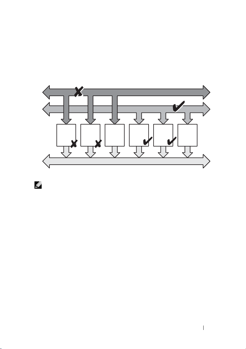
for some reason CMC is unable to maintain grid redundancy, then E-mail
Power
Supply
#1
Power
Supply
#2
Empty
Slot
#3
Power
Supply
#4
Power
Supply
#5
Empty
Slot
#6
DC Power Grid #1
DC Power Grid #2
Chassis DC Power Bus
and/or SNMP alerts are sent to administrators if the Redundancy Lost event
is configured for alerting.
Figure 1-1. 2 PSUs per grid and a power failure on grid 1
DC Power Grid #1
NOTE: In the event of a single PSU failure in this configuration, the remaining PSUs
in the failing grid are marked as Online. In this state, any of the remaining PSUs can
fail without interrupting operation of the system. If a PSU fails, the chassis health is
marked non-critical. If the smaller grid cannot support the total chassis power
allocations then grid redundancy status is reported as No Redundancy and Chassis
health is displayed as Critical.
Power Supply Redundancy Mode
The power supply redundancy mode is useful when redundant power grids are
not available, but you may want to be protected against a single PSU failure
bringing down your servers in a modular enclosure. The highest capacity PSU
is kept in online reserve for this purpose. This forms a Power Supply
redundancy pool. Figure 1-2 illustrates power supply redundancy mode. PSUs
beyond those required for power and redundancy are still available and is
added to the pool in the event of a failure. Unlike grid redundancy, when
power supply redundancy is selected CMC does not require the PSU units to
be present in any specific PSU slot positions.
Carrier Grade Chassis Management Controller User’s Guide Addendum 7
Page 8
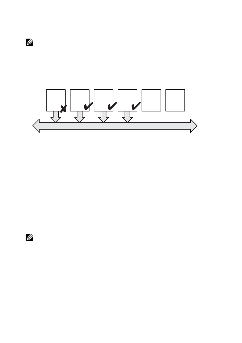
NOTE: Dynamic Power Supply Engagement (DPSE) allows PSUs to be placed in
Power
Supply
#1
Power
Supply
#2
Power
Supply
#3
Power
Supply
#4
Empty
Slot
#5
Empty
Slot
#6
Chassis DC Power Bus
Dual or Single Power Grid:
Power Supply Redundancy protects against failure
of a single power supply.
standby. The standby state indicates a physical state: that of not supplying power.
When you enable DPSE, the extra PSUs may be placed in Standby mode to increase
efficiency and save power.
Figure 1-2. Power Supply Redundancy: Totally 4 PSUs with a failure of one PSU.
No Redundancy Mode
The no redundancy mode is the factory default setting for a 3 PSU
configuration and indicates that the chassis does not have any power
redundancy configured. In this configuration, the overall redundancy status
of the chassis always indicates No Redundancy. Figure 1-3 illustrates no
redundancy mode is the factory default setting for 3 PSU configuration.
CMC does not require the PSU units to be present in any specific PSU slot
positions when No Redundancy is configured.
NOTE: All PSUs in the chassis are Online if DPSE is disabled when in No
Redundancy mode. When DPSE is enabled all active PSUs in the chassis are listed
as Online and additional PSUs may be turned to Standby to increase the system's
power efficiency.
8 Carrier Grade Chassis Management Controller User’s Guide Addendum
Page 9
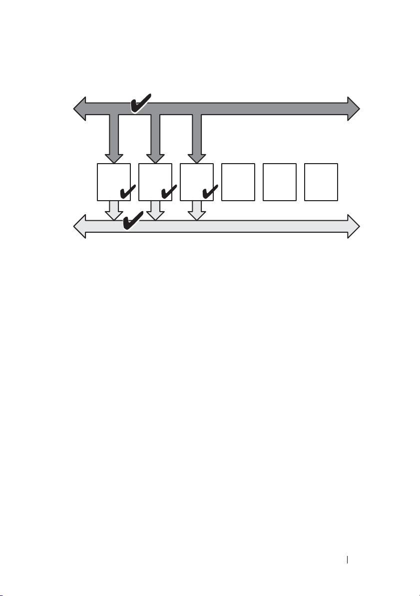
Figure 1-3. No Redundancy with three PSUs in the chassis
Power
Supply
#1
Power
Supply
#2
Power
Supply
#3
Empty
Slot
#4
Empty
Slot
#5
Empty
Slot
#6
DC Power Grid #1
Chassis DC Power Bus
Single Power Grid:
No protection against grid or power supply failure
A PSU failure brings other PSUs out of Standby mode, as needed, to support
the chassis power allocations. If you have 4 PSUs, and require only three, then
in the event that one fails, the fourth PSU is brought online. A chassis can
have all 6 PSUs online.
When you enable DPSE, the extra PSUs may be placed in Standby mode to
increase efficiency and save power. For more information, see
Supply Engagement
.
Dynamic Power
Power Budgeting for Hardware Modules
Figure 1-4 illustrates a chassis that contains a six-PSU configuration. The
PSUs are numbers 1-6, starting on the left-side of the enclosure.
Carrier Grade Chassis Management Controller User’s Guide Addendum 9
Page 10
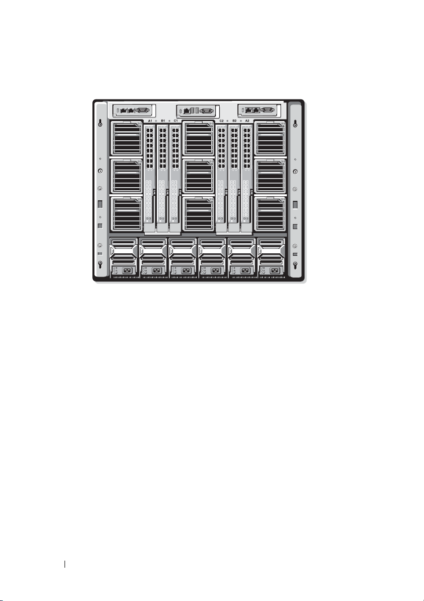
Figure 1-4. Chassis With Six-PSU Configuration
PSU1 PSU2 PSU3 PSU4 PSU5 PSU6
CMC maintains a power budget for the enclosure that reserves the necessary
wattage for all installed servers and components. CMC allocates power to the
CMC infrastructure and the servers in the chassis. CMC infrastructure
consists of components in the chassis, such as fans, I/O modules, and iKVM
(if present). The chassis may have up to 32 servers that communicate to the
chassis through the iDRAC. For more information, see the iDRAC User's
Guide at support.dell.com/manuals.
iDRAC provides CMC with its power envelope requirements before powering
up the server. The power envelope consists of the maximum and minimum
power requirements necessary to keep the server operating. iDRAC's initial
estimate is based on its initial understanding of components in the server.
After operation commences and further components are discovered, iDRAC
may increase or decrease its initial power requirements.
When a server is powered-up in an enclosure, the iDRAC software reestimates the power requirements and requests a subsequent change in the
power envelope.
10 Carrier Grade Chassis Management Controller User’s Guide Addendum
Page 11

CMC grants the requested power to the server, and the allocated wattage is
subtracted from the available budget. Once the server is granted a power
request, the server's iDRAC software continuously monitors the actual power
consumption. Depending on the actual power requirements, the iDRAC
power envelope may change over time. iDRAC requests a power step-up only
if the servers are fully consuming the allocated power.
Under heavy load the performance of the server's processors may be degraded
to ensure power consumption stays below the user-configured System Input
Power Cap. The PowerEdge M1000e enclosure can supply enough power for
peak performance of most server configurations, but many available server
configurations do not consume the maximum power that the enclosure can
supply. To help data centers provision power for their enclosures, the M1000e
allows you to specify a System Input Power Cap to ensure that the overall
chassis input power draw stays under a given threshold. CMC first ensures
enough power is available to run the fans, IO Modules, iKVM (if present),
and CMC itself. This power allocation is called the Input Power Allocated to
Chassis Infrastructure. Following Chassis Infrastructure, the servers in an
enclosure are powered up. Any attempt to set a System Input Power Cap
below the actual consumption fails.
If necessary for the total power budget to stay below the value of the System
Input Power Cap, CMC allocates servers a value less than their maximum
requested power. Servers are allocated power based on their Server Priority
setting, with higher priority servers getting maximum power, priority 2 servers
getting power after priority 1 servers, and so on. Lower priority servers may get
less power than priority 1 servers based on System Input Max Power Capacity
and the user-configured setting of System Input Power Cap.
Configuration changes, such as an additional server in the chassis, may
require the System Input Power Cap to be increased. Power needs in a
modular enclosure also increase when thermal conditions change and the fans
are required to run at higher speed, which causes them to consume additional
power. Insertion of I/O modules and iKVM also increases the power needs of
the modular enclosure. A fairly small amount of power is consumed by servers
even when they are powered down to keep the management controller
powered up.
Carrier Grade Chassis Management Controller User’s Guide Addendum 11
Page 12

Additional servers can be powered up in the modular enclosure only if
sufficient power is available. The System Input Power Cap can be increased
any time up to a maximum value of 16685 watts to allow the power up of
additional servers.
Changes in the modular enclosure that reduce the power allocation are:
•Server power off
•Server
•I/O module
• iKVM removal
• Transition of the chassis to a powered off state
You can reconfigure the System Input Power Cap when chassis is either ON or
OFF.
NOTE: While inserting a server with geometry other than single height and if there
is insufficient power for the iDRAC, the server is displayed as multiple single-height
servers.
Server Slot Power Priority Settings
CMC allows you to set a power priority for each of the sixteen server slots in
an enclosure. The priority settings are 1 (highest) through 9 (lowest). These
settings are assigned to slots in the chassis, and the slot's priority is inherited
by any server inserted in that slot. CMC uses slot priority to preferentially
budget power to the highest priority servers in the enclosure.
According to the default server slot priority setting, power is equally
apportioned to all slots. Changing the slot priorities allows administrators to
prioritize which servers are given preference for power allocations. If the more
critical server modules are left at their default slot priority of 1, and the less
critical server modules are changed to lower priority value of 2 or higher, the
priority 1 server modules would be powered on first. These higher priority
servers would then get their maximum power allocation, while lower priority
servers may be not be allocated enough power to run at their maximum
performance or they may not even power on at all, depending on how low the
system input power cap is set and the server power requirements. If an
administrator manually powers on the low priority server modules before the
higher priority ones, then the low priority server modules are the first modules
to have their power allocation lowered down to the minimum value, in order
12 Carrier Grade Chassis Management Controller User’s Guide Addendum
Page 13

to accommodate the higher priority servers. So after the available power for
allocation is exhausted, then CMC reclaims power from lower or equal
priority servers until they are at their minimum power level.
NOTE: I/O modules, fans, and iKVM (if present) are given the highest priority. CMC
reclaims power only from lower priority devices to meet the power needs of a
higher priority module or server.
Dynamic Power Supply Engagement
Dynamic Power Supply Engagement (DPSE) mode is disabled by default.
DPSE saves power by optimizing the power efficiency of the PSUs supplying
power to the chassis. This also results in increased PSU life, and reduced heat
generation.
CMC monitors total enclosure power allocation, and moves the PSUs into
Standby state, causing the total power allocation of the chassis to be delivered
through fewer PSUs. Since the online PSUs are more efficient when running
at higher utilization, this improves their efficiency while also improving
longevity of the standby PSUs.
To operate remaining PSUs at their maximum efficiency:
• No Redundancy mode with DPSE is highly power efficient, with optimal
PSUs online. PSUs that are not needed are placed in standby mode.
• PSU Redundancy mode with DPSE also provides power efficiency. At least
two supplies are online, with one PSU required to power the configuration
and one to provide redundancy in case of PSU failure. PSU Redundancy
mode offers protection against the failure of any one PSU, but offers no
protection in the event of input power grid loss.
• Grid Redundancy mode with DPSE, where at least two of the supplies are
active, one on each power grid, provides a good balance between efficiency
and maximum availability for a partially-loaded modular enclosure
configuration.
• Disabling DPSE provides the lowest efficiency as all six supplies are active
and share the load, resulting in lower utilization of each power supply.
DPSE can be enabled for all three power supply redundancy configurations
explained above - No Redundancy, Power Supply Redundancy, and Grid
Redundancy.
Carrier Grade Chassis Management Controller User’s Guide Addendum 13
Page 14

• In a No Redundancy configuration with DPSE, the M1000e can have up to
five power supply units in Standby state. In a six PSU configuration, some
PSU units are placed in Standby and are not utilized to improve power
efficiency. Removal or failure of an online PSU in this configuration cause
a PSU in Standby state to change to Online; however, standby PSUs can
take up to two seconds to become active, so some server modules may lose
power during the transition in the No Redundancy configuration.
NOTE: In a three PSU configuration, server load may prevent any PSUs from
transitioning to Standby.
• In a Power Supply Redundancy configuration, the enclosure always keeps
an additional PSU powered on and marked Online in addition to the PSUs
required to power the enclosure. Power utilization is monitored and up to
four PSUs could be moved to Standby state depending on the overall
system load. In a six PSU configuration, a minimum of two power supply
units are always powered on.
Since an enclosure in the Power Supply Redundancy configuration always
has an extra PSU engaged, the enclosure can tolerate the loss of one online
PSU and still have enough power for the installed server modules. The loss
of the online PSU causes a standby PSU to come online. Simultaneous
failure of multiple PSUs may result in the loss of power to some server
modules while the standby PSUs are powering up.
• In Grid Redundancy configuration, all power supplies are engaged at
chassis power up. Power utilization is monitored, and if system
configuration and power utilization allows, PSUs are moved to the
Standby state. Since the Online status of PSUs in a grid mirrors that of the
other grid, the enclosure can sustain the loss of power to an entire grid
with no interruption of power to the enclosure.
An increase in power demand in the Grid Redundancy configuration
causes the engagement of PSUs from the Standby state. This maintains
the mirrored configuration needed for dual-grid redundancy.
NOTE: With DPSE Enabled, the Standby PSUs are brought Online to reclaim power
if power demand increases in all three Power Redundancy policy modes.
14 Carrier Grade Chassis Management Controller User’s Guide Addendum
Page 15

Redundancy Policies
Redundancy policy is a configurable set of properties that determine how
CMC manages power to the chassis. The following redundancy policies are
configurable with or without dynamic PSU engagement:
• Grid Redundancy
•Power Supply Redundancy
• No Redundancy
The default redundancy configuration for a chassis depends on how many
PSUs it contains, as shown in Table 1-1.
Table 1-1. Default Redundancy Configuration
PSU Configuration Default Redundancy Policy Default Dynamic PSU
Engagement Setting
Six PSUs Grid Redundancy Disabled
Three PSUs No Redundancy Disabled
Grid Redundancy
In Grid Redundancy mode with six PSUs, all six PSUs are active. The three
PSUs on the left must connect to one AC power grid, while the three PSUs on
the right connect to another AC power grid.
CAUTION:
If one AC grid fails, the PSUs on the functioning power grid take over without
interruption to the servers or infrastructure.
CAUTION:
To avoid a system failure and for Grid Redundancy to work effectively, there
must be a balanced set of PSU properly cabled to separate input power grids.
In AC redundancy mode, you must have balanced sets of PSUs (at least one
PSU in each grid). If this condition is not met, AC redundancy may not be possible.
Power Supply Redundancy
When power supply redundancy is enabled, a PSU in the chassis is kept as a
spare, ensuring that the failure of any one PSU does not cause the servers or
chassis to power-down. Power Supply Redundancy mode requires up to four
PSUs. Additional PSUs, if present, are utilized to improve power efficiency of
the system if DPSE is enabled. Subsequent failures after loss of redundancy
may cause the servers in the chassis to power down.
Carrier Grade Chassis Management Controller User’s Guide Addendum 15
Page 16

No Redundancy
Power in excess of what is necessary to power the chassis is available, even on
a failure, to continue to power the chassis.
CAUTION:
The No Redundancy mode uses optimum PSUs when DPSE is enabled for the
requirements of the chassis. Failure of a single PSU could cause servers to lose
power and data in this mode.
Power Conservation and Power Budget Changes
CMC performs power conservation when the user-configured maximum
power limit is reached. When the demand for power exceeds the user
configured System Input Power Cap, CMC reduces power to servers in
reverse-priority order to free power for higher priority servers and other
modules in the chassis.
If all or multiple slots in the chassis are configured with the same priority
level, CMC decreases power to servers in increasing slot number order. For
example, if the servers in slots 1 and 2 have the same priority level, the power
for the server in slot 1 is decreased before that of the server in slot 2.
NOTE: You can assign a priority level to each of the servers in the chassis by giving
each server a number from 1 through 9. The default priority level for all servers is 1.
The lower the number, the higher the priority level.
For instructions on assigning server priority levels, see
to Servers
in the Chassis Management Controller 4.1 User's Guide.
You can assign server priority using the GUI:
1
Click Servers in the system tree.
2
Click
Power Priority
.
Assigning Priority Levels
Power Conservation and Max Conservation Mode
CMC performs maximum power conservation when:
• The user selects maximum conservation mode using the Web interface or
RACADM.
• An automated command line script, issued by a UPS device, selects
maximum conservation mode.
16 Carrier Grade Chassis Management Controller User’s Guide Addendum
Page 17

In maximum power conservation mode, all servers start functioning at their
minimum power levels, and all subsequent server power allocation requests
are denied. In this mode, the performance of powered on servers may be
degraded. Additional servers cannot be powered on, regardless of server
priority.
The system is restored to full performance when the user or an automated
command line script clears the maximum conservation mode.
Using Web Interface
You can select or clear the Max Power Conservation mode using the GUI:
1
Click
Chassis Overview
2
Click
Power Configuration
3
Select the
Max Power Conservation Mode
conservation and click
4
Clear the
and click
Using RACADM
Max Power Conservation
Apply
.
in the system tree.
.
Apply
.
Mode box to restore normal operation
box to enable maximum power
Open a serial, Telnet, or SSH console to CMC and log in.
• To enable the maximum power consumption mode, type:
racadm config -g cfgChassisPower -o
cfgChassisMaxPowerConservationMode 1
• To restore normal operation, type:
r
acadm config -g cfgChassisPower -o
cfgChassisMaxPowerConservationMode 0
Server Performance Over Power Redundancy
When enabled, this option favors server performance and server power up,
over maintaining power redundancy. When disabled, the system favors power
redundancy over server performance. When disabled, then if the power
supplies in the chassis do not provide sufficient power, both for redundancy,
as well as full performance, then in order to preserve redundancy, some servers
may not be:
Carrier Grade Chassis Management Controller User’s Guide Addendum 17
Page 18

• Granted sufficient power for full performance.
• Powered on.
Using Web Interface
To enable Server Performance Over Power Redundancy, perform the following
steps:
1
Click Chassis Overview in the system tree.
2
Click
Power Configuration
3
Select
Server Performance Over Power Redundancy
Using RACADM
To enable Server Performance Over Power Redundancy, perform the following
steps:
1
Open a
2
Enable
racadm config -g cfgChassisPower -o
cfgChassisPerformanceOverRedundancy 1
To disable Server Performance Over Power Redundancy, perform the
following steps:
1
Open a
2
Disable
r
serial, Telnet, or SSH
Server Performance Over Power Redundancy
serial, Telnet, or SSH text console
Server Performance Over Power Redundancy
acadm config -g cfgChassisPower -o
.
and click
text console to CMC and log in.
:
to CMC and log in.
:
Apply.
cfgChassisPerformanceOverRedundancy 0
Remote Logging
Power consumption can be reported to a remote syslog server. Total chassis
power consumption, minimum, maximum, and average power consumption
over a collection period can be logged. For more information on enabling this
feature and configuring the collection/logging interval, see related sections
below.
18 Carrier Grade Chassis Management Controller User’s Guide Addendum
Page 19

Using Web Interface
You can enable power remote logging using the GUI. To do this, log in to the
GUI, and do the following:
1
Click
Chassis Overview
2
Click
Power Configuration
3
Select
Power Remote Logging
remote host.
4
Specify the required logging interval (1-1440 minutes).
5
Click
Apply
to save changes.
in the system tree.
.
, to enable you to log power events to a
Using RACADM
Open a serial, Telnet or SSH text console to CMC, log in, and configure
power remote logging as shown:
1
To enable the power remote logging feature, enter the following command:
racadm config -g cfgRemoteHosts -o
cfgRhostsSyslogPowerLoggingEnabled 1
2
To specify the desired logging interval, enter the following command:
racadm config -g cfgRemoteHosts -o
cfgRhostsSyslogPowerLoggingEnabled 1
where n is 1-1440 minutes.
3
To determine if the power remote logging feature is enabled, enter the
following command:
racadm getconfig -g cfgRemoteHosts -o
cfgRhostsSyslogPowerLoggingEnabled
4
To determine the power remote logging interval, enter the following
command:
racadm getconfig -g cfgRemoteHosts -o
cfgRhostsSyslogPowerLoggingInterval
Carrier Grade Chassis Management Controller User’s Guide Addendum 19
Page 20

NOTE: The power remote logging feature is dependent on remote syslog hosts
having been previously configured. Logging to one or more remote syslog hosts
must be enabled, otherwise power consumption is logged. This can be done either
through the Web GUI or the RACADM CLI. For more information, see the remote
syslog configuration instructions.
PSU Failure With Degraded or No Redundancy Policy
CMC decreases power to servers when an insufficient power event occurs,
such as a PSU failure. After decreasing power on servers, CMC re-evaluates
the power needs of the chassis. If power requirements are still not met, CMC
powers off lower priority servers.
Power for higher priority servers is restored incrementally while power needs
remain within the power budget.
NOTE: To set the redundancy policy, see
Redundancy
.
Configuring Power Budget and
New Server Engagement Policy
When a new server is powered on, CMC may need to decrease power to lower
priority servers to allow more power for the new server if adding the new
server exceeds the power available for the chassis. This could happen if the
administrator has configured a power limit for the chassis that is below what
would be required for full power allocation to the servers, or if insufficient
power is available for the worst-case power need of all servers in the chassis. If
enough power cannot be freed by reducing the allocated power of the lower
priority servers, the new server may not be allowed to power up.
The highest amount of sustained power required to run the chassis and all of
the servers, including the new one, at full power is the worst-case power
requirement. If that amount of power is available, then no servers are
allocated power that is less than the worst-case power needed and the new
server is allowed to power up.
If the worst-case power requirement cannot be met, power is reduced to the
lower priority servers until enough power is freed to power up the new server.
20 Carrier Grade Chassis Management Controller User’s Guide Addendum
Page 21

Table 1-2 describes the actions taken by CMC when a new server is powered
on in the scenario described earlier.
Table 1-2. CMC Response When a Server Power-On is Attempted
Worst Case Power is
Available
Yes No power conservation is
No Perform power conservation:
CMC Response Server Power On
Allowed
required
• Power required for new server is
available
• Power required for new server is
not available
Allowed
Not Allowed
If a PSU fails, it results in a non-critical health state and a PSU failure event is
generated. The removal of a PSU results in a PSU removal event.
If either event results in a loss of redundancy, based on power allocations, a
loss of redundancy event is generated.
If the subsequent power capacity or the user power capacity is greater than
the server allocations, servers have degraded performance or, in a worse case,
servers may be powered down. Both conditions are in reverse-priority order,
that is, the lower priority servers are powered down first.
Table 1-3 describes the firmware response to a PSU power down or removal as
it applies to various PSU redundancy configurations.
Table 1-3. Chassis Impact from PSU Failure or Removal
PSU Configuration Dynamic PSU Engagement Firmware Response
Grid Redundancy Disabled CMC alerts you of loss of
Grid Redundancy.
Power Supply
Redundancy
Carrier Grade Chassis Management Controller User’s Guide Addendum 21
Disabled Decrease power to low
priority servers, as
required.
Page 22

Table 1-3. Chassis Impact from PSU Failure or Removal
PSU Configuration Dynamic PSU Engagement Firmware Response
Grid Redundancy Enabled CMC alerts you of loss of
Grid Redundancy. PSUs
in standby mode (if any)
are turned on to
compensate for power
budget lost from the PSU
failure or removal.
Power Supply
Redundancy
No Redundancy Enabled Decrease power to low
Enabled CMC alerts you of loss of
Power Supply
Redundancy. PSUs in
standby mode (if any) are
turned on to compensate
for power budget lost
from PSU failure or
removal.
priority servers, as
required.
PSU Removals With Degraded or No Redundancy Policy
CMC may begin conserving power when you remove a PSU or a PSU AC
cord. CMC decreases power to the lower priority servers until power
allocation is supported by the remaining PSUs in the chassis. If you remove
more than one PSU, CMC evaluates power needs again when the second PSU
is removed to determine the firmware response. If power requirements are
still not met, CMC may power off the lower priority servers.
Limitations
• CMC does not support automated power-down of a lower priority server to
allow power up of a higher priority server; however, you can perform user
initiated power-downs.
22 Carrier Grade Chassis Management Controller User’s Guide Addendum
Page 23

• Changes to the PSU redundancy policy are limited by the number of PSUs
in the chassis. You can select any of the three PSU redundancy
configuration settings. For more information, see Redundancy Policies.
Power Supply and Redundancy Policy Changes in System Event Log
Changes in the power supply state and power redundancy status are recorded
as events. Events related to the power supply that record entries in the system
event log (SEL) are power supply insertion and removal, power supply input
insertion and removal, and power supply output assertion and de-assertion.
Events related to changes in the power redundancy status that record entries
in the SEL are redundancy loss and redundancy regain for the modular
enclosure that is configured for either a Grid Redundancy power policy or
Power Supply Redundancy power policy.
Table 1-4 lists the SEL entries that are related to power supply state and
power redundancy status.
Table 1-4. SEL Events for Power Supply Changes
Power Supply Event System Event Log (SEL) Entry
Insertion Power supply <number> is present
Removal Power supply <number> is absent
Grid or Power Supply Redundancy lost Power supply redundancy is lost.
Grid or Power Supply Redundancy
regained
Input power received The input power for power supply
Input power lost The power input for power supply
DC output produced Power supply <number> is operating
DC Output lost Power supply <number> failed.
Input over-voltage An over voltage fault detected on power
The power supplies are redundant.
<number> has been restored.
<number> is lost.
normally.
supply <number>.
Carrier Grade Chassis Management Controller User’s Guide Addendum 23
Page 24

Table 1-4. SEL Events for Power Supply Changes
Power Supply Event System Event Log (SEL) Entry
Input under-voltage An under voltage fault detected on power
supply <number>.
Input over-current An over current fault detected on power
supply <number>.
Input under-current An under current fault detected on power
supply <number>.
DC output over-voltage An output over voltage fault detected on
power supply <number>.
DC output under-voltage An output under voltage fault detected on
power supply <number>.
DC output over-current An output over current fault detected on
power supply <number>.
DC output under-current An output under current fault detected on
power supply <number>.
Communication failure Cannot communicate with power supply
<number>.
Communication restored Communication has been restored to power
supply <number>.
Failure to communicate status data Cannot obtain status information from
power supply <number>.
Status data communication restored Power supply <number> status information
successfully obtained.
Over/Under-temperature The temperature for power supply
<number> is outside of range.
Fan or Airflow error/warning Fan failure detected on power supply
<number>.
Fan speed overridden Fan failure detected on power supply
<number>.
Manufacturing fault Power supply <number> failed.
Microprocessor busy Power supply <number> failed.
FRU error Power supply <number> failed.
24 Carrier Grade Chassis Management Controller User’s Guide Addendum
Page 25

Table 1-4. SEL Events for Power Supply Changes
Power Supply Event System Event Log (SEL) Entry
Other fault Power supply <number> failed.
Redundancy Status and Overall Power Health
The redundancy status is a factor in determining the overall power health.
When the power redundancy policy is set, for example, to Grid Redundancy
and the redundancy status indicates that the system is operating with
redundancy, the overall power health is typically OK. However, if the
conditions for operating with grid redundancy cannot be met, the redundancy
status is No, and the overall power health is Critical. This is because the
system is not able to operate in accordance with the configured redundancy
policy.
NOTE: CMC does not perform a pre-check of these conditions when you change
the redundancy policy to or from grid redundancy. So, configuring the redundancy
policy may immediately result in redundancy lost or a regained condition.
Configuring and Managing Power
You can use the Web-based and RACADM interfaces to manage and
configure power controls on CMC. Specifically, you can:
• View power allocations, consumption, and status for the chassis, servers,
and PSUs.
• Configure System Input Power Cap and Redundancy Policy for the chassis.
• Execute power control operations (power-on, power-off, system reset
power-cycle) for the chassis.
Viewing the Health Status of the PSUs
The Power Supply Status page displays the status and readings of the PSUs
associated with the chassis.
Using Web Interface
The PSU health status can be viewed in two ways, from the Chassis Graphics
section on the Chassis Status page or the Power Supply Status page.
Carrier Grade Chassis Management Controller User’s Guide Addendum 25
Page 26

The Chassis Graphics page provides a graphical overview of all PSUs installed
in the chassis.
To view health status for all PSUs using Chassis Graphics:
1
Log in to the CMC Web interface.
The Chassis Status page is displayed. The lower section of Chassis
Graphics depicts the rear view of the chassis and contains the health status
of all PSUs. PSU health status is indicated by the color of the PSU subgraphic:
• Green - PSU is present, powered on and communicating with CMC;
there is no indication of an adverse condition.
• Amber - Indicates a PSU failure. See the CMC log for details on the
failure condition.
• Gray - Occurs during PSU initialization and when the PSU is set to
standby, during Chassis power up, or PSU insertion. PSU is present
and not powered on. There is no indication of an adverse condition.
2
Use the cursor to hover over the individual PSU sub-graphic and a
corresponding text hint or screen tip is displayed. The text hint provides
additional information on that PSU.
The PSU sub-graphic is hyperlinked to the corresponding CMC GUI page
to provide immediate navigation to the
PSUs.
Power Supply Status
page for all
To view the health status of the PSUs using Power Supply Status:
1
Log in to the CMC Web interface.
2
Select
Power Supplies
The
Power Supply Status
Table 1-5 and Table 1-7 provide descriptions of the information provided on
the Power Supply Status page.
26 Carrier Grade Chassis Management Controller User’s Guide Addendum
in the system tree.
page is displayed.
Page 27

Table 1-5. Power Supplies
Item Description
Name Displays the name of the power supply unit: PS-[n], where [n] is
the power supply number.
Present Indicates whether the PSU is Present or Absent.
Health OK Indicates that the PSU is present and
communicating with CMC. In the event of a
communication failure between CMC and the
power supply, CMC cannot obtain or display
health status for the PSU.
Warning Indicates that only Warning alerts have been
issued, and corrective action must be taken.
If corrective actions are not taken, it could lead
to critical or severe power failures that can
affect the integrity of the chassis.
Severe Indicates that at least one Failure alert has
been issued for the power supply. Severe status
indicates a power failure on the chassis, and
corrective action must be taken immediately.
Power Status Displays the power state of the power supplies (one of the
following): Initializing, Online, Stand By, In Diagnostics, Failed,
Offline, Unknown, or Absent.
Capacity Displays the power supply’s capacity in watts.
Table 1-6. System Power Status
PSU Configuration Dynamic PSU Engagement
Overall Power Health Displays the health status (OK, Non-Critical,
Critical, Non-Recoverable, Other, Unknown) of
the power management for the entire chassis.
System Power Status Displays the power status (On, Off, Powering
On, Powering Off) of the chassis.
Carrier Grade Chassis Management Controller User’s Guide Addendum 27
Page 28

Table 1-6. System Power Status
PSU Configuration Dynamic PSU Engagement
Redundancy Displays the power supply redundancy status.
Using RACADM
(continued)
Valu e s i n clu de:
No: Power Supplies are not redundant.
Ye s: Full Redundancy in effect.
Open a serial/Telnet/SSH text console to CMC, log in, and type:
racadm getpminfo
For more information about getpminfo, including output details, see the
RACADM Command Line Reference Guide for iDRAC7 1.00.00 and CMC 4.1
available on the Dell Support website at support.dell.com/manuals.
Viewing Power Consumption Status
CMC provides the actual input power consumption for the entire system on
the Power Monitoring Status page.
Using the Interface
NOTE: To perform power management actions, you must have Chassis
Configuration Administrator privilege.
To view power consumption status using the Web interface:
1
Log in to the CMC Web interface.
2
Select
3
Chassis Overview
Click
Power Power Monitoring
The
Power Monitoring
in the system tree.
.
page displays.
NOTE: You can also view the power redundancy status under Power Supplies in
the System tree Status tab.
Table 1-7 through Table 1-10 describe the information displayed on the
Power Monitoring page.
28 Carrier Grade Chassis Management Controller User’s Guide Addendum
Page 29

Table 1-7. System Power Status
Item Description
Overall Power Health Indicates the health status of the chassis' power subsystem:
• Green check icon for OK
• Yellow exclamation icon for non-critical
• Red x icon for critical
System Power Status Displays the power status (On, Off, Powering On, Powering
Off) of the chassis.
Redundancy Displays the redundancy status. Valid values are:
• No - PSUs are not redundant.
• Yes - Full redundancy in effect.
Table 1-8. Real-Time Power Statistics
Item Description
System Input Power Displays the current cumulative power consumption of all
modules in the chassis measured from the input side of the
PSUs. The value for system input power is indicated in both
watts and BTU/h units.
Peak System Power Displays the maximum system level input power
consumption since the value was last cleared. This property
allows you to track the maximum power consumption by the
system (chassis and modules) recorded over a period of time.
Click Reset Peak/Min Power Statistics below the table to
clear this value. The value for peak system power is indicated
in both watts and BTU/h units.
Peak System Power
Start Time
Displays the date and time recorded when the peak system
power consumption value was last cleared. The timestamp is
displayed in the format hh:mm:ss MM/DD/YYYY, where hh
is hours (0-24), mm is minutes (00-60), ss is seconds (00-60),
MM is the month (1-12), DD is the day (1-31), and YYYY is
the year. This value is reset with the Reset Peak/Min Power
Statistics button and also when CMC resets or fails over.
Carrier Grade Chassis Management Controller User’s Guide Addendum 29
Page 30

Table 1-8. Real-Time Power Statistics
Item Description
Peak System Power
Timestamp
Peak System Power
Timestamp
Minimum System
Power Start Time
Minimum System
Power Timestamp
Displays the minimum system level input power
consumption value (in watts) over the time since the user last
cleared this value. This property allows you to track the
minimum power consumption by the system (chassis and
modules) recorded over a period of time. Click Reset
Peak/Min Power Statistics below the table to clear this value.
The value for minimum system power is displayed in both
watts and BTU/h units. This value is reset with the Reset
Peak/Min Power Statistics button and also when CMC resets
or fails over.
Displays the date and time recorded when the minimum
system power consumption value was last cleared. The
timestamp is displayed in the format hh:mm:ss
MM/DD/YYYY, where hh is hours (0-24), mm is minutes (00-
60), ss is seconds (00-60), MM is the month (1-12), DD is the
day (1-31), and YYYY is the year. This value is reset with the
Reset Peak/Min Power Statistics button and also when CMC
resets or fails over.
Displays the date and time recorded when the minimum
system power consumption occurred over the time period
being recorded. The format of the timestamp is the same as
described for Peak System Power Timestamp.
(continued)
30 Carrier Grade Chassis Management Controller User’s Guide Addendum
Page 31

Table 1-8. Real-Time Power Statistics
Item Description
System Idle Power Displays the estimated power consumption of the chassis
when it is in idle state. The idle state is defined as the state of
the chassis while it is ON and all modules are consuming
power while in the idle state. This is an estimated value and
not a measured value. It is computed as the cumulative
power allocated to chassis infrastructure components (I/O
modules, fans, iKVM, iDRAC controllers and front panel
LCD) and the minimum power requirement of all servers
that have been allocated power and that are in the poweredon state. The value for system idle power is displayed in both
watts and BTU/h units.
System Potential
Power
System Input
Current Reading
Displays the estimated power consumption of the chassis
when it is operating at maximum power. The maximum
power consumption is defined as the state of the chassis
while it is ON and all modules are consuming maximum
power. This is an estimated value derived from historical
aggregate power consumption of the system configuration and
not a measured value. It is computed as the cumulative power
allocated to chassis infrastructure components (I/O modules,
fans, iKVM, iDRAC controllers and the front panel LCD)
and the maximum power requirement of all servers that have
been allocated power and are in the powered-on state. The
value for system potential power is displayed in both watts
and BTU/h units.
Displays the total input current draw of the chassis based on
the sum of the input current draw of each of the individual
PSU modules in the chassis. The value for system input
current reading is displayed in Amps.
(continued)
Carrier Grade Chassis Management Controller User’s Guide Addendum 31
Page 32

Table 1-9. Real-Time Energy Statistics Status
Item Description
System Energy
Consumption
System Energy
Consumption Start
Time
System Energy
Consumption
Timestamp
Table 1-10. Server Modules
Displays the current cumulative energy consumption for all
modules in the chassis measured from the input side of the
power supplies. The value is displayed in KWh and it is a
cumulative value.
Displays the date and time recorded when the system energy
consumption value was last cleared, and the new
measurement cycle began. The timestamp is displayed in the
format hh:mm:ss MM/DD/YYYY, where hh is hours (0-24),
mm is minutes (00-60), ss is seconds (00-60), MM is the
month (1-12), DD is the day (1-31), and YYYY is the year.
This value is reset with the Reset Energy Statistics button,
but persists through a CMC reset or failover operation.
Displays the date and time when the system energy
consumption was calculated for display. The timestamp is
displayed in the format hh:mm:ss MM/DD/YYYY, where hh is
hours (0-24), mm is minutes (00-60), ss is seconds (00-60),
MM is the month (1-12), DD is the day (1-31), and YYYY is
the year.
Item Description
Slot Displays the location of the server module. The Slot is a
sequential number (1-16) that identifies the server module by
its location within the chassis.
Name Displays the server name. The server name can be redefined
by the user.
Present Displays whether the server is present in the slot (Yes or No).
If this field displays Extension of # (where the # is 1-8), then
number that follows it is the main slot of a multi-slot server.
Actual (Input) Real-time measurement of the actual power consumption of
the server. The measurement is displayed in watts.
32 Carrier Grade Chassis Management Controller User’s Guide Addendum
Page 33

Table 1-10. Server Modules
Item Description
Cumulative Power
Start Time
Peak Consumption
Time Stamp
Real-time measurement of the cumulative power that the
server has consumed since the time displayed in the Start
Time field. The measurement is presented in kilowatt hours
(kWh).
Displays the peak power that the server consumed at one
time. The time when the peak power consumption occurred is
recorded in the Time Stamp field. The measurement is
displayed in watts.
Viewing Power Budget Status
CMC provides power status overviews of the power subsystem on the Power
Budget Status page.
Using Web Interface
NOTE: To perform power management actions, you must have Chassis
Configuration Administrator privilege.
To view power budget status using Web interface:
1
Log in to the CMC Web interface.
2
Select
Chassis Overview
3
Click
Power Budget Status
The Power Budget Status page displays.
in the system tree.
.
Table Table 1-12 through Table 1-15describe the information displayed on
the Power Budget Status page.
For information about configuring the settings for this information, see
Configuring Power Budget and Redundancy
Using RACADM
.
Open a serial/Telnet/SSH text console to CMC, log in, and type:
racadm getpbinfo
For more information about getpbinfo, including output details, see the
getpbinfo command section in the RACADM Command Line Reference
Guide Addendum for Carrier Grade Chassis Management Controller.
Carrier Grade Chassis Management Controller User’s Guide Addendum 33
Page 34

Table 1-11. System Power Policy Configuration
Item Description
System Input
Power Cap
Displays the user configured maximum power consumption limit
for the entire system (chassis, CMC, servers, I/O modules, power
supply units, iKVM, and fans). CMC enforces this limit via
reduced server power allocations, or by powering off lower
priority server modules. The value for system input power cap is
displayed in watts, BTU/h and percent units. If the chassis power
consumption exceeds the System Input Power Cap, then the
performance of lower priority servers is reduced until total power
consumption falls below the cap. In cases where the servers are
set to the same priority, then the selection of the server for power
reduction, or power-off action, is based on the server slot number
order. For example, the server in slot 1 is selected first and the
server in slot 16 is selected last.
34 Carrier Grade Chassis Management Controller User’s Guide Addendum
Page 35

Table 1-11. System Power Policy Configuration
Item Description
Redundancy
Policy
Displays the current redundancy configuration: AC Redundancy,
Power Supply Redundancy, and No Redundancy.
•
Grid Redundancy
PSUs. Half of them should be cabled to one power grid and the
other half should be cabled to another grid. When the system is
running optimally in Grid Redundancy mode, power is loadbalanced across all active supplies. In case of a grid failure, the
PSUs on the functioning power grid take over without
interruption.
Power Supply Redundancy
•
PSU in the chassis is held in reserve, ensuring that a failure of
any one PSU does not cause the server modules or chassis to
power down.
Power Supply Redundancy may not use all six PSUs; it uses
sufficient PSUs to assure that on the failure of any one the
remaining can continue to supply power to the chassis. The
other PSUs may be placed in Standby mode if DPSE is enabled.
No Redundancy
•
to power the entire chassis, including the chassis, servers, I/O
modules, iKVM, and CMC. The remaining PSUs may be placed
in standby mode if DPSE is enabled.
- Power input is load-balanced across all
- The power from all active PSUs is sufficient
CAUTION: The No Redundancy mode uses only the minimum
required number of PSUs at a time, with no backup. Failure of one
of the PSUs in use could cause the server modules to lose power
and data.
Dynamic Power
Supply
Engagement
Displays whether Dynamic Power Supply Engagement is enabled
or disabled. Enabling this feature allows CMC to put underutilized PSUs into standby mode based on the redundancy policy
that is set and the power requirements of the system. Putting
under-utilized PSUs into standby mode increases the utilization,
and efficiency, of the online PSUs, saving power.
- The capacity of the highest-rated
Carrier Grade Chassis Management Controller User’s Guide Addendum 35
Page 36

Table 1-12. Power Budgeting
Item Description
System Input
Max Power
Capacity
Input
Redundancy
Reserve
Input Power
Allocated to
Servers
Input Power
Allocated to
Chassis
Infrastructure
Input Power
Allocated to
Servers
Total Input Power
Available for
Allocation
Standby Input
Power Capacity
Maximum input power that the available power supplies can
supply to the system (in watts).
Displays the amount of redundant power (in watts) in reserve that
can be utilized in the event of an input power grid or power supply
unit (PSU) failure. When the chassis is configured to operate in
Grid Redundancy mode, the Input Redundancy Reserve is the
amount of reserve power that can be utilized in the event of an
input power grid failure. When the chassis is configured to
operate in Power Supply Redundancy mode, the Input
Redundancy Reserve is the amount of reserve power that can be
utilized in the event of a PSU failure.
Displays (in watts) the cumulative input power that CMC
allocates to servers based on their configuration.
Displays (in watts) the cumulative input power that CMC
allocates to the chassis infrastructure (Fans, IO modules, iKVM,
CMC, Standby CMC and iDRAC on servers).
Displays the total chassis power, in watts, still available for
allocation.
Displays the total chassis power, in watts, still available for
allocation.
Displays the amount of standby input power (in watts) that is
available in the event of a Power Supply fault or Power Supply
removal from the system. This field may show a reading when the
system has multiple power supplies and the Dynamic Power
Supply Engagement is enabled.
36 Carrier Grade Chassis Management Controller User’s Guide Addendum
Page 37

Table 1-13. Server Modules
Item Description
Slot Displays the location of the server module. The Slot is a
sequential number (1-16) that identifies the server module by its
location within the chassis.
Name Displays the server name. The server name is defined by the user.
Type Displays the type of the server.
Priority of the
relocated server.
Displays the priority level allotted to the server slot in the chassis
for power budgeting. CMC uses this value in its calculations
when power must be reduced or reallocated based on userdefined power limits or power supply or power grid failures.
Priority levels: 1 (highest) through 9 (lowest)
Default: 1
NOTE: Server slot priority level is associated with the server slot-
not with the server inserted into the slot. If you move a server to a
different slot in the chassis or to a different chassis, the priority
previously associated with new slot determines the priority
Power State Displays the power status of the server:
• N/A: CMC has not determined the power state of the server.
• Off: Either the server or chassis is off.
• On: Both chassis and server are on.
• Powering On: Temporary state between Off and On. When the
powering on cycle completes, the Power State changes to On.
• Powering Off: Temporary state between On and Off. When the
powering off cycle completes, the Power State changes to Off.
Budget Allocation
- Actual
Displays the power budget allocation for the server module.
Actual: Current power budget allocation for each server.
Carrier Grade Chassis Management Controller User’s Guide Addendum 37
Page 38

Table 1-14. Chassis Power Supplies
Item Description
Name Displays the name of the PSU in the format PS-n, where n, is the
PSU number.
Power State Displays the power state of the PSU - Initializing, Online, Stand
By, In Diagnostics, Failed, Unknown, or Absent (missing).
Input Volts Displays the present input voltage of the power supply.
Input Current Displays the present input current of the power supply.
Output Rated
Power
Displays the maximum output power rating of the power supply.
Configuring Power Budget and Redundancy
CMC's power management service optimizes power consumption for the
entire chassis (the chassis, servers, IOMs, iKVM, CMC, and PSUs) and reallocates power to different modules based on the demand.
Using Web Interface
NOTE: To perform power management actions, you must have Chassis
Configuration Administrator privilege.
To configure power budget using the Web interface:
1
Log in to the CMC Web interface.
2
Select
Chassis Overview
3
Click
Power Configuration
The Budget/Redundancy Configuration page is displayed.
4
Set any or all of the properties described in Table x-16 according to your
needs.
5
Click
Apply
to save your changes.
To refresh the content on the Budget/Redundancy Configuration page, click
Refresh. To print the contents, click Print.
in the system tree.
.
38 Carrier Grade Chassis Management Controller User’s Guide Addendum
Page 39

Table 1-15. Configurable Power Budget/Redundancy Properties
Item Description
System Input Power Cap System Input Power Cap is the maximum input power
that the system is allowed to allocate to servers and chassis
infrastructure. It can be configured by the user to any value
that exceeds the minimum power needed for servers that
are powered on and the chassis infrastructure; configuring
a value that falls below the minimum power needed for
servers and the chassis infrastructure fails.
The power allocated to Servers and Chassis Infrastructure
can be found in the User Interface on the Chassis
Overview PowerPower Budget Status page under
Power Budgeting section or by using the CLI RACADM
utility command (
Users can power off one or more server(s) to lower the
current power allocation, and re-attempt setting a lower
value for System Input Power Cap (if desired) or simply
configure the cap prior to powering on the servers.
To change this setting, it is possible to enter a value in any
of the units. The interface ensures that the unit field that
was last changed is the value that is submitted when those
changes are applied.
racadm getpbinfo).
NOTE: For capacity planning, see the Datacenter Capacity
Planner (DCCP) tool at www.dell.com/calc.
NOTE: When value changes are specified in watts, the
submitted value exactly reflects the value that is applied.
However, when the changes are submitted in either of the
BTU/h or percent units, the submitted value may not exactly
reflect the value that is applied. This is because these units
are converted to watts and then applied; and the conversion
is susceptible to some rounding error.
Carrier Grade Chassis Management Controller User’s Guide Addendum 39
Page 40

Table 1-15. Configurable Power Budget/Redundancy Properties
Item Description
Redundancy Policy This option allows you to select one the following options:
•
No Redundancy
to power the entire chassis, including the chassis, servers,
I/O modules, iKVM, and CMC. No power supplies must
be kept in reserve.
: Power from the power supplies is used
NOTE: The No Redundancy mode uses only the minimum
required number of power supplies at a time. If the minimum
number of PSUs are installed, then there is no backup
available. Failure of one of the three power supplies being
used could cause the servers to lose power and/or data. If
more than the minimum required number of PSUs are
present, then the additional PSUs may be placed in Standby
mode for improving power efficiency if DPSE is enabled.
•
Power Supply Redundancy:
rated power supply in the chassis is kept in reserve,
ensuring that a failure of any one power supply does not
cause the server modules or chassis to power down (hot
spare).
Power Supply Redundancy mode may not utilize all
installed power supplies. Any additional power supplies, if
present, may be placed in Standby mode for improving
power efficiency, when DPSE is enabled. Power Supply
Redundancy mode prevents server modules from
powering up if the power consumption of the chassis
exceeds the rated power. Failure of two power supplies
may cause some or all server modules in the chassis to
power down. Server module performance is not degraded
in this mode.
Grid Redundancy:
•
two power grids (for example, PSUs 1-3 make up power
grid 1 and PSUs 4-6 make up power grid 2). Failure of a
PSU or loss of input power to one grid reports the
redundancy status as lost.
This mode divides half the PSUs into
The capacity of the highest-
40 Carrier Grade Chassis Management Controller User’s Guide Addendum
Page 41

Table 1-15. Configurable Power Budget/Redundancy Properties
Item Description
Server Performance Over
Power Redundancy
Enable Dynamic Power
Supply Engagement
Disable Chassis Power
Button
Allow 110 VAC
Operation
Max Conservation Mode On selection, immediately enters the maximum power
This option favors server performance and server power up,
over maintaining power redundancy. For more information
about this feature, see
Redundancy
On selection, enables dynamic power management. In
Dynamic Engagement mode, the power supplies are
turned ON (online) or OFF (standby) based on power
consumption, optimizing the energy consumption of the
entire chassis. For example, your power budget is 5000
watts, your redundancy policy is set to Grid Redundancy
mode, and you have six power supply units. CMC
determines that four of the power supply units can manage
the grid redundancy while the other two remain in standby
mode. If an additional 2000W of power is needed for newly
installed servers or power efficiency of the existing system
configuration is required to be improved, then the two
standby power supply units are engaged.
On selection, disables the chassis power button. If the
check box is selected and you attempt to change the power
state of the chassis by pressing the chassis power button,
the action is ignored.
In a NEBS enabled chassis this option is disabled. The
Carrier Grade CMC firmware only supports DC input
operation.
conservation mode. For more information, see
Conservation and Max Conservation Mode
.
Server Performance Over Power
Power
.
Carrier Grade Chassis Management Controller User’s Guide Addendum 41
Page 42

Using RACADM
To enable and set the redundancy policy:
NOTE: To perform power management actions, you must have Chassis
Configuration Administrator privilege.
1
Open a serial/Telnet/SSH text console to CMC and log in.
2
Set properties as needed:
• To select a redundancy policy, type:
racadm config -g cfgChassisPower -o
cfgChassisRedundancyPolicy <value>
where <value> is 0 (No Redundancy), 1 (Grid Redundancy), 2 (Power
Supply Redundancy).
The default is 0.
For example, the following command:
racadm config -g cfgChassisPower -o
cfgChassisRedundancyPolicy 1
sets the redundancy policy to 1.
• To enable or disable dynamic PSU engagement, type:
racadm config -g cfgChassisPower -o
cfgChassisDynamicPSUEngagementEnable <value>
where <value> is 0 (disable), 1 (enable). The default is 0.
For example, the following command:
racadm config -g cfgChassisPower -o
cfgChassisDynamicPSUEngagementEnable 0
disables dynamic PSU engagement.
For information about RACADM commands for chassis power, see the
config, getconfig, and cfgChassisPower sections in the RACADM Command
Line Reference Guide for iDRAC7 and CMC and getpbinfo in the RACADM
Command Line Reference Guide Addendum for Carrier Grade Chassis
Management Controller.
42 Carrier Grade Chassis Management Controller User’s Guide Addendum
Page 43

Assigning Priority Levels to Servers
Server priority levels determine which servers the CMC draws power from
when additional power is required.
NOTE: The priority you assign to a server is linked to its slot and not to the server
itself. If you move the server to a new slot, you must reconfigure the priority for the
new slot location.
NOTE: To perform power management actions, you must have Chassis
Configuration Administrator privilege.
Using the Web Interface
To assign priority levels using the CMC Web interface:
1
Log in to the CMC Web interface.
2
Select
Servers Overview
The
Servers Status
3
Click
Power Server Priority.
The
Server Priority
4
Select a priority level (1-9, with 1 holding the highest priority) for one,
multiple, or all servers. The default value is 1. You can assign the same
priority level to multiple servers.
5
Click
Apply
to save your changes.
in the system tree.
page is displayed.
page appears, listing all of the servers in your chassis.
Using RACADM
Open a serial/Telnet/SSH text console to CMC, log in, and type:
racadm config -g cfgServerInfo -o cfgServerPriority i <slot number> <priority level>
where <slot number> (1-16) refers to the location of the server, and
<priority level> is a value between 1-9.
For example, the following command:
racadm config -g cfgServerInfo -o cfgServerPriority -i
5 1
Sets the priority level to 1 for the server in slot 5.
Carrier Grade Chassis Management Controller User’s Guide Addendum 43
Page 44

Setting Power Budget
NOTE: To perform power management actions, you must have Chassis
Configuration Administrator privilege.
Using the Web Interface
To set the power budget using the CMC Web interface:
1
Log in to the CMC Web interface.
2
Click
Chassis Overview
The Chassis Health page is displayed.
3
Click the
The
4
Click the
The
5
Type a budget value of up to 16685 watts in the
text
6
Click
Power
Power Monitoring Status
Configuration
Budget/Redundancy Configuration
field.
NOTE: The power budget is limited to a maximum of which ever set of three
PSUs that is the weakest. If you attempt to set an AC power budget value that
exceeds this value, CMC displays a failure message.
NOTE: When value changes are specified in watts, the submitted value
exactly reflects the value that is applied. However, when the changes are
submitted in either of the BTU/h or percent units, the submitted value may not
exactly reflect the value that is applied. This is because these units are
converted to watts and then applied; and the conversion is susceptible to
some rounding error.
Apply
to save your changes.
in the system tree.
tab.
page appears.
subtab.
page is displayed.
System Input Power Cap
Using RACADM
Open a serial/Telnet/SSH text console to CMC, log in, and type:
racadm config -g cfgChassisPower -o
cfgChassisPowerCap <value>
where <value> is a number between 2715-16685 representing the maximum
power limit in watts. The default is 16685.
For example, the following command:
44 Carrier Grade Chassis Management Controller User’s Guide Addendum
Page 45

racadm config -g cfgChassisPower -o
cfgChassisPowerCap 5400
sets the maximum power budget to 5400 watts.
NOTE: The power budget is limited to 16685 Watts. If you attempt to set an input
power budget value that exceeds the power capacity of your chassis, CMC displays
a failure message.
Server Power Reduction to Maintain Power Budget
CMC reduces power allocations of lower priority servers when additional
power is needed to maintain the system power consumption within the userconfigured System Input Power Cap. For example, when a new server is
engaged, CMC may decrease power to low priority servers to allow more
power for the new server. If the amount of power is still insufficient after
reducing power allocations of the lower priority servers, CMC lowers the
performance of servers until sufficient power is freed to power the new server.
CMC reduces server power allocation in two cases:
• Overall power consumption exceeds the configurable System Input Power
Cap (see Setting Power Budget).
• A power failure occurs in a non-redundant configuration.
For information about assigning priority levels to servers, see
Priority Levels to Servers
.
Assigning
Carrier Grade Chassis Management Controller User’s Guide Addendum 45
Page 46

46 Carrier Grade Chassis Management Controller User’s Guide Addendum
 Loading...