


Dell Chassis Management Controller Version 1.4 for
PowerEdge FX2/FX2s
User's Guide

Notes, cautions, and warnings
NOTE: A NOTE indicates important information that helps you make better use of your product.
CAUTION: A CAUTION indicates either potential damage to hardware or loss of data and tells you how to avoid the
problem.
WARNING: A WARNING indicates a potential for property damage, personal injury, or death.
© 2016 Dell Inc. All rights reserved. This product is protected by U.S. and international copyright and intellectual property laws. Dell and the Dell
logo are trademarks of Dell Inc. in the United States and/or other jurisdictions. All other marks and names mentioned herein may be trademarks of
their respective companies.
2016 - 10
Rev. A00

Contents
1 Overview.........................................................................................................................11
Key Features......................................................................................................................................................................11
What is new in this release..........................................................................................................................................12
Management features.................................................................................................................................................12
Security features.........................................................................................................................................................13
Chassis overview.............................................................................................................................................................. 13
Supported remote access connections.............................................................................................................................14
Supported platforms.........................................................................................................................................................15
Supported web browsers..................................................................................................................................................15
Supported firmware versions............................................................................................................................................16
Supported Firmware Versions for Server Component Update..........................................................................................16
Supported Network Adapters...........................................................................................................................................16
Managing licenses............................................................................................................................................................. 17
Storage sled licenses...................................................................................................................................................17
Types of licenses.........................................................................................................................................................18
Acquiring licenses........................................................................................................................................................18
License operations...................................................................................................................................................... 18
Licensable features in CMC........................................................................................................................................ 19
License component state or condition and available operations..................................................................................19
Viewing localized versions of the CMC web interface......................................................................................................20
Supported management console applications.................................................................................................................. 20
How to use this User's Guide........................................................................................................................................... 20
Other documents you may need...................................................................................................................................... 20
Accessing documents from Dell support site.................................................................................................................... 21
2 Installing and setting up CMC....................................................................................... 22
Installing CMC hardware.................................................................................................................................................. 22
Checklist to set up chassis......................................................................................................................................... 22
Daisy chain FX2 CMC network connection................................................................................................................ 23
Using remote access software from a management station...................................................................................... 25
Remote RACADM installation.....................................................................................................................................27
Installing remote RACADM on a Windows management station.................................................................................27
Installing remote RACADM on a Linux management station.......................................................................................27
Uninstalling remote RACADM from a Linux management station...............................................................................28
Configuring a web browser........................................................................................................................................ 28
Downloading and updating CMC firmware.................................................................................................................29
Setting chassis physical location and chassis name....................................................................................................29
Setting date and time on CMC...................................................................................................................................29
Configuring LEDs to identify components on the chassis...........................................................................................30
Configuring CMC properties...................................................................................................................................... 30
Configuring front panel.............................................................................................................................................. 30
3

Configuring chassis management at server mode.............................................................................................................31
Configuring chassis management at server using CMC web interface........................................................................31
Configuring chassis management at server mode using RACADM..............................................................................31
3 Logging into CMC......................................................................................................... 33
Configure public key authentication over SSH................................................................................................................. 33
Generating public keys for systems running Windows................................................................................................33
Generating public keys for systems running Linux......................................................................................................34
Accessing CMC web interface.........................................................................................................................................34
Logging into CMC as a local user, active directory user, or LDAP user............................................................................ 34
Logging into CMC using a smart card.............................................................................................................................. 35
Logging into CMC using Single Sign-On...........................................................................................................................36
Logging into CMC using serial, Telnet, or SSH console.................................................................................................... 36
Logging into CMC using public key authentication...........................................................................................................36
Multiple CMC sessions..................................................................................................................................................... 37
4 Updating firmware........................................................................................................ 38
Signed CMC firmware image............................................................................................................................................38
Downloading CMC firmware............................................................................................................................................ 38
Viewing currently installed firmware versions...................................................................................................................38
Viewing currently installed firmware versions using CMC web interface....................................................................38
Viewing currently installed firmware versions using RACADM....................................................................................39
Updating the CMC firmware............................................................................................................................................39
Updating CMC firmware using web interface............................................................................................................ 39
Updating CMC firmware using RACADM...................................................................................................................40
Updating the CMC using DUP......................................................................................................................................... 40
Updating chassis infrastructure firmware.........................................................................................................................40
Updating chassis infrastructure firmware using CMC web interface..........................................................................40
Updating chassis infrastructure firmware using RACADM.......................................................................................... 41
Updating server iDRAC firmware...................................................................................................................................... 41
Updating server iDRAC firmware using web interface................................................................................................ 41
Updating server component firmware........................................................................................................................42
Enabling Lifecycle Controller...................................................................................................................................... 44
Choosing server component firmware update type using CMC web interface...........................................................44
Filtering components for firmware updates................................................................................................................44
Viewing firmware inventory........................................................................................................................................45
Saving chassis inventory report using CMC web interface.........................................................................................46
Configuring network share using CMC web interface................................................................................................46
Lifecycle Controller job operations..............................................................................................................................47
5 Viewing chassis information and monitoring chassis and component health.................. 51
Viewing chassis and component summaries......................................................................................................................51
Chassis graphics......................................................................................................................................................... 51
Selected component information................................................................................................................................51
Viewing server model name and Service Tag............................................................................................................. 53
Viewing storage model name and Service Tag........................................................................................................... 53
4

Viewing chassis summary.................................................................................................................................................53
Viewing chassis controller information and status............................................................................................................53
Viewing information and health status of all servers.........................................................................................................53
Viewing information and health status of storage sleds....................................................................................................53
Viewing information and health status of the IOMs..........................................................................................................54
Viewing information and health status of fans..................................................................................................................54
Configuring fans.........................................................................................................................................................55
Viewing front panel properties......................................................................................................................................... 55
Viewing KVM information and health status.................................................................................................................... 55
Viewing information and health status of temperature sensors........................................................................................55
6 Configuring CMC..........................................................................................................56
Enabling or disabling DHCP for the CMC Network Interface Address..............................................................................56
Enabling the CMC network interface...............................................................................................................................56
Enabling or disabling DHCP for DNS IP addresses............................................................................................................57
Setting static DNS IP addresses.......................................................................................................................................57
Viewing and modifying CMC network LAN settings.........................................................................................................58
Viewing and modifying CMC network LAN settings using CMC web interface..........................................................58
Viewing and modifying CMC network LAN settings using RACADM......................................................................... 58
Configuring DNS settings (IPv4 and IPv6).......................................................................................................................58
Configuring auto negotiation, duplex mode, and network speed (IPv4 and IPv6)............................................................ 59
Configuring Management Port 2......................................................................................................................................59
Configuring Management Port 2 using CMC web interface.......................................................................................59
Configuring Management Port 2 using RACADM............................................................................................................ 60
Federal Information Processing Standards.......................................................................................................................60
Enabling FIPS Mode Using CMC Web Interface.........................................................................................................60
Enabling FIPS Mode Using RACADM..........................................................................................................................61
Disabling FIPS Mode................................................................................................................................................... 61
Configuring services......................................................................................................................................................... 61
Configuring services using RACADM.......................................................................................................................... 61
Configuring CMC extended storage card.........................................................................................................................62
Setting up Chassis Group.................................................................................................................................................62
Adding members to Chassis Group............................................................................................................................ 63
Removing a member from the leader......................................................................................................................... 63
Disbanding a Chassis Group....................................................................................................................................... 63
Disabling an individual Member at the Member chassis..............................................................................................64
Launching the web page of a Member chassis or server............................................................................................64
Propagating Leader chassis properties to Member chassis........................................................................................64
Synchronizing a new Member with Leader chassis properties................................................................................... 65
Server inventory for MCM group...............................................................................................................................65
Saving server inventory report...................................................................................................................................65
Chassis Configuration Profiles..........................................................................................................................................66
Saving Chassis Configuration.....................................................................................................................................66
Restoring Chassis Configuration Profile..................................................................................................................... 66
Viewing Stored Chassis Configuration Profiles...........................................................................................................67
Importing Chassis Configuration Profiles....................................................................................................................67
5

Applying Chassis Configuration Profiles......................................................................................................................67
Exporting Chassis Configuration Profiles....................................................................................................................67
Editing Chassis Configuration Profiles........................................................................................................................68
Deleting Chassis Configuration Profiles......................................................................................................................68
Configuring Multiple CMCs through RACADM Using Chassis Configuration Profiles.......................................................68
Exporting Chassis Configuration profiles....................................................................................................................68
Importing Chassis Configuration profiles.................................................................................................................... 69
Parsing Rules............................................................................................................................................................. 69
Configuring multiple CMCs using RACADM..................................................................................................................... 69
Parsing rules...............................................................................................................................................................70
Modifying the CMC IP address................................................................................................................................... 71
7 Configuring servers....................................................................................................... 73
Configuring slot names.....................................................................................................................................................73
Configuring iDRAC network settings................................................................................................................................74
Configuring iDRAC QuickDeploy network settings..................................................................................................... 74
QuickDeploy IP address assignments for servers....................................................................................................... 76
Modifying iDRAC Network Settings for individual server iDRAC.................................................................................77
Modifying iDRAC network settings using RACADM....................................................................................................77
Configuring iDRAC VLAN tag settings........................................................................................................................77
Configuring iDRAC VLAN tag settings using web interface........................................................................................78
Configuring iDRAC VLAN tag settings using RACADM.............................................................................................. 78
Setting first boot device...................................................................................................................................................78
Setting first boot device for multiple servers using CMC web interface.....................................................................79
Setting first boot device for individual server using CMC web interface.................................................................... 79
Setting first boot device using RACADM....................................................................................................................79
Configuring sled network uplink....................................................................................................................................... 80
Deploying remote file share..............................................................................................................................................80
Configuring server FlexAddress........................................................................................................................................80
Configuring profile settings using server configuration replication.................................................................................... 81
Accessing Profile page................................................................................................................................................81
Managing stored profiles.............................................................................................................................................81
Adding or saving profile..............................................................................................................................................82
Applying profile...........................................................................................................................................................82
Importing profile.........................................................................................................................................................83
Exporting profile.........................................................................................................................................................83
Editing profile............................................................................................................................................................. 83
Viewing profile settings.............................................................................................................................................. 84
Viewing stored profile settings................................................................................................................................... 84
Viewing profile log...................................................................................................................................................... 84
Completion status and troubleshooting......................................................................................................................84
Quick Deploy of profiles............................................................................................................................................. 85
Assigning server profiles to slots ............................................................................................................................... 85
Boot Identity Profiles..................................................................................................................................................85
Saving Boot Identity Profiles...................................................................................................................................... 86
Applying Boot Identity Profiles................................................................................................................................... 86
6

Clearing Boot Identity Profiles.................................................................................................................................... 87
Viewing Stored Boot Identity Profiles.........................................................................................................................87
Importing Boot Identity Profiles..................................................................................................................................87
Exporting Boot Identity Profiles..................................................................................................................................87
Deleting Boot Identity Profiles....................................................................................................................................88
Managing Virtual MAC Address Pool..........................................................................................................................88
Creating MAC Pool.................................................................................................................................................... 88
Adding MAC Addresses..............................................................................................................................................88
Removing MAC Addresses.........................................................................................................................................89
Deactivating MAC Addresses.....................................................................................................................................89
Launching iDRAC using Single Sign-On............................................................................................................................89
Launching iDRAC from Server Status page............................................................................................................... 90
Launching iDRAC from Servers Status page..............................................................................................................90
Launching remote console from server status page.........................................................................................................90
8 Configuring storage sleds.............................................................................................. 91
Configuring storage sleds in split-single mode...................................................................................................................91
Configuring storage sleds in split-dual mode..................................................................................................................... 91
Configuring storage sleds in joined mode.......................................................................................................................... 91
Configuring storage sleds using CMC web interface.........................................................................................................91
Configuring storage sleds using RACADM........................................................................................................................92
Managing storage sleds using iDRAC RACADM proxy..................................................................................................... 92
Viewing storage array status............................................................................................................................................92
9 Configuring CMC to send alerts....................................................................................93
Enabling or disabling alerts............................................................................................................................................... 93
Enabling or disabling alerts using CMC web interface................................................................................................ 93
Enabling or disabling alerts using RACADM................................................................................................................93
Filtering alerts.............................................................................................................................................................93
Configuring alert destinations...........................................................................................................................................93
Configuring SNMP trap alert destinations..................................................................................................................93
Configuring e-mail alert settings.................................................................................................................................95
10 Configuring user accounts and privileges.....................................................................97
Types of users..................................................................................................................................................................97
Modifying root user administrator account settings....................................................................................................... 100
Configuring local users....................................................................................................................................................100
Configuring local users using CMC web interface.....................................................................................................100
Configure local users using RACADM........................................................................................................................101
Configuring Active Directory users..................................................................................................................................101
Supported Active Directory authentication mechanisms........................................................................................... 101
Standard schema Active Directory overview.............................................................................................................101
Configuring standard schema Active Directory.........................................................................................................102
Extended schema Active Directory overview........................................................................................................... 102
Configuring extended schema Active Directory........................................................................................................103
Configuring generic LDAP users..................................................................................................................................... 103
7

Configuring the generic LDAP directory to access CMC.......................................................................................... 103
Configuring generic LDAP directory service using CMC web interface.................................................................... 103
Configuring generic LDAP directory service using RACADM.................................................................................... 104
11 Configuring CMC for Single Sign-On or Smart Card login.......................................... 105
System requirements......................................................................................................................................................105
Client Systems..........................................................................................................................................................105
CMC.........................................................................................................................................................................105
Prerequisites for Single Sign-On or Smart Card login..................................................................................................... 106
Generating Kerberos keytab file......................................................................................................................................106
Configuring CMC for Active Directory schema...............................................................................................................106
Configuring browser for SSO login................................................................................................................................. 106
Internet Explorer.......................................................................................................................................................106
Mozilla Firefox...........................................................................................................................................................107
Configuring browser for Smart Card login.......................................................................................................................107
Configuring CMC SSO login or Smart Card login for Active Directory users using RACADM..........................................107
Configuring CMC SSO Or Smart Card Login For Active Directory Users Using Web Interface...................................... 107
Uploading Keytab file......................................................................................................................................................108
Configuring CMC SSO login or Smart Card login for Active Directory users using RACADM......................................... 108
12 Configuring CMC to use Command Line consoles...................................................... 109
CMC Command Line console features........................................................................................................................... 109
CMC Command Line interface commands............................................................................................................... 109
Using Telnet console with CMC..................................................................................................................................... 109
Using SSH with CMC................................................................................................................................................ 110
Supported SSH cryptography schemes.....................................................................................................................110
Configure public key authentication over SSH...........................................................................................................110
Configuring terminal emulation software..........................................................................................................................111
Connecting to servers or I/O module using Connect command.......................................................................................111
Configuring the managed server BIOS for serial console redirection......................................................................... 112
Configuring Windows for serial console redirection................................................................................................... 113
Configuring Linux for server serial console redirection during boot............................................................................113
Configuring Linux for server serial console redirection after boot..............................................................................114
Managing CMC using iDRAC RACADM proxy.................................................................................................................115
13 Using FlexAddress and FlexAddress Plus cards...........................................................116
About FlexAddress.......................................................................................................................................................... 116
About FlexAddress Plus.............................................................................................................................................116
Verifying FlexAddress activation................................................................................................................................117
Deactivating FlexAddress.......................................................................................................................................... 118
Configuring FlexAddress..................................................................................................................................................118
Configuring FlexAddress for chassis-level fabric and slots.........................................................................................118
Viewing World Wide Name/Media Access Control (WWN/MAC) IDs.......................................................................118
Command messages....................................................................................................................................................... 119
FlexAddress DELL SOFTWARE LICENSE AGREEMENT................................................................................................120
Viewing WWN/MAC address information....................................................................................................................... 121
8

Viewing basic WWN/MAC address information using web interface..............................................................................122
Viewing advanced WWN/MAC address information using web interface.......................................................................122
Viewing WWN/MAC address information using RACADM............................................................................................. 123
14 Managing Fabrics....................................................................................................... 125
Monitoring IOM health....................................................................................................................................................125
Configuring network settings for IOM............................................................................................................................ 125
Configuring network settings for IOM using CMC web interface............................................................................. 125
Configuring network settings for IOM using RACADM.............................................................................................126
Viewing I/O module uplink and downlink status using web interface.............................................................................. 126
Viewing I/O module FCoE session information using web interface................................................................................126
Resetting IOM to factory default settings...................................................................................................................... 126
Updating IOM software using CMC web interface......................................................................................................... 127
IOA/MXL GUI................................................................................................................................................................. 127
Launching IOA/MXL GUI from the Chassis Overview page......................................................................................127
Launching IOA/MXL GUI from the I/O Module Overview page................................................................................128
Launching IOA/MXL GUI from the I/O Module Status page.................................................................................... 128
I/O Aggregator Module.................................................................................................................................................. 128
15 Using VLAN Manager................................................................................................. 129
Assigning VLAN to IOM.................................................................................................................................................. 129
Configuring VLAN settings on IOMs using CMC web interface .....................................................................................129
Viewing the VLAN settings on IOMs using CMC web interface......................................................................................130
Viewing the current VLAN settings on IOMs using CMC web interface......................................................................... 130
Removing VLANs for IOMs using CMC web interface....................................................................................................130
Updating untagged VLANs for IOMs using CMC web interface..................................................................................... 130
Resetting VLANs for IOMs using CMC web interface..................................................................................................... 131
16 Managing and monitoring power................................................................................ 132
Redundancy policies....................................................................................................................................................... 132
Grid Redundancy policy............................................................................................................................................ 133
No Redundancy policy.............................................................................................................................................. 133
Redundancy Alerting Only policy (Default setting)....................................................................................................133
PSU failures.............................................................................................................................................................. 133
Default Redundancy configuration..................................................................................................................................133
Multi-node sled adaptation............................................................................................................................................. 133
Chassis power limit monitoring........................................................................................................................................133
Viewing power consumption status................................................................................................................................ 133
Viewing power consumption status using CMC web interface................................................................................. 134
Viewing power consumption status using RACADM.................................................................................................134
Viewing power budget status using CMC web interface................................................................................................ 134
Viewing power budget status using RACADM................................................................................................................134
Redundancy status and overall power health..................................................................................................................134
Power management after PSU failure...................................................................................................................... 134
Power supply and Redundancy policy changes in system event log..........................................................................134
Configuring power budget and redundancy..............................................................................................................135
9

Executing Power Control Operations........................................................................................................................137
Executing Power Control Operations for Multiple Servers Using CMC Web Interface..............................................137
Executing Power Control Operations on the IOM.....................................................................................................138
17 Configuring PCIe slots................................................................................................139
Viewing PCIe slot properties using CMC web interface..................................................................................................140
Viewing PCIe slot properties using RACADM..................................................................................................................140
PCIe reassignment....................................................................................................................................................140
18 Troubleshooting and recovery.................................................................................... 142
Gathering configuration information, chassis status, and logs using RACDUMP.............................................................142
Supported interfaces................................................................................................................................................ 142
Downloading SNMP Management Information Base (MIB) file................................................................................ 143
First steps to troubleshoot a remote system............................................................................................................ 143
Troubleshooting Alerts..............................................................................................................................................144
Viewing Event Logs.................................................................................................................................................. 144
Using Diagnostic Console..........................................................................................................................................144
Resetting Components.............................................................................................................................................145
Saving or Restoring Chassis Configuration............................................................................................................... 145
Troubleshooting Network Time Protocol (NTP) Errors.............................................................................................145
Interpreting LED colors and blinking patterns........................................................................................................... 146
Troubleshooting Network Problems..........................................................................................................................149
General troubleshooting..................................................................................................................................................149
Troubleshooting storage module in FX2 chassis....................................................................................................... 149
Resetting Forgotten Administrator Password.................................................................................................................150
19 Frequently asked questions........................................................................................152
RACADM........................................................................................................................................................................152
Managing and recovering a remote system.................................................................................................................... 152
Active Directory..............................................................................................................................................................153
IOM................................................................................................................................................................................ 154
Event and error messages.............................................................................................................................................. 154
10

1
Overview
The Dell Chassis Management Controller (CMC) for PowerEdge FX2/FX2s is a Systems Management hardware and software
solution for managing the PowerEdge FX2/FX2s chassis. The CMC has its own microprocessor and memory and is powered by the
modular chassis into which it is plugged.
The CMC enables an IT administrator to:
• View inventory.
• Perform configuration and monitoring tasks.
• Remotely turn on and turn off chassis and servers.
• Enable alerts for events on servers and components in the server module.
• View the PCIe mapping information and reassign PCIe slots.
• Provide a one–many management interface to the iDRACs and I/O modules in the chassis.
The CMC provides multiple System Management functions for servers. Power and thermal management are the primary functions
of CMC, which are listed as follows:
• Enclosure-level real-time automatic power and thermal management.
– The CMC reports real-time power consumption, which includes logging high and low points with a time stamp.
– The CMC supports setting an optional enclosure maximum power limit (System Input Power Cap), which alerts and takes
actions such as limiting the power consumption of servers, and/or preventing the turning on of new servers to keep the
enclosure under the defined maximum power limit.
– The CMC monitors and automatically controls the functions of cooling fans based on actual ambient and internal
temperature measurements.
– The CMC provides comprehensive enclosure inventory and status or error reporting.
• The CMC provides a mechanism for centralized configuration of the:
– Network and security setting of the PowerEdge FX2/FX2s enclosure.
– Power redundancy and power ceiling settings.
– I/O switch and iDRAC network settings.
– First boot device on the server module.
– I/O fabric consistency checks between the I/O module and servers. CMC also disables components, if necessary, to protect
the system hardware.
– User access security.
– PCIe slots.
You can configure CMC to send email alerts or SNMP trap alerts for warnings or errors such as temperature, hardware
misconfiguration, power outage, and fan speed.
NOTE: The terms “storage sled” and “storage module” are used interchangeably in this document.
Key Features
The CMC features are grouped into management and security features.
11

What is new in this release
This release of CMC for Dell PowerEdge FX2/FX2s supports:
• Performing racresetcfg from CMC GUI.
• Enabling Federal Information Processing Standards (FIPS) 140-2 cryptography.
• Disabling AC Power Recovery.
• Updating the OpenSSL open source package to version 1.0.2f.
• Updating the OpenSSH open source package to version 7.1p1.
• Updating glibc to version 2.23 to address new security vulnerabilities.
• TLS 1.2 and TLS 1.1 by default.
• User configuration option to enable TLS 1.0 using RACADM.
• Configuring SNMPv3 using RACADM commands.
• Querying the health status of the chassis components using WSMan.
• Initiating Quick Deploy of blade through RACADM.
• Configuring CMC using WSMan for the following features:
– Host name of chassis
– IP Configuration
– DNS
– DNS Registration
– NTP
– Change Default Password
• Sending alerts when the power state of an IOM changes and when power-on of IOM fails.
• Populating CMC Device name in the inventory.
Management features
CMC provides the following management features:
• Dynamic Domain Name System (DDNS) registration for IPv4 and IPv6.
• Login management and configuration for local users, Active Directory, and LDAP.
• Remote system management and monitoring using SNMP, a web interface, integrated KVM, Telnet, or SSH connection.
• Monitoring — Provides access to system information and status of components.
• Access to system event logs — Provides access to the hardware log and chassis log.
• Firmware updates for various chassis components — Enables you to update the firmware for CMC, iDRAC on servers, storage
sleds, and chassis infrastructure.
• Firmware update of server components such as BIOS and network controllers across multiple servers in the chassis using
Lifecycle Controller.
• Dell OpenManage software integration — Enables you to launch the CMC web interface from Dell OpenManage Server
Administrator or OpenManage Essentials (OME) 1.2.
• CMC alert — Alerts you about potential managed node issues through Remote syslog email message or SNMP trap.
• Remote power management — Provides remote power management functions, such as turn off and reset of any chassis
component, from a management console.
• Power usage reporting.
• Secure Sockets Layer (SSL) encryption — Provides secure remote system management through the web interface.
• Launch point for the Integrated Dell Remote Access Controller (iDRAC) web interface.
• Support for WS-Management.
• Multi-node Sled adaptation. PowerEdge FM120x4 is a multi-node Sled.
• Chassis Power Limit Monitoring.
12
• iDRAC IO Identity feature support for enhanced WWN/MAC Address Inventory.
• FlexAddress feature — Replaces the factory-assigned World Wide Name/Media Access Control (WWN/MAC) IDs with
chassis-assigned WWN/MAC IDs for a particular slot, an optional upgrade.
• Graphical display of chassis component status and health.
• Support for single and multi-slot servers.
• iDRAC single sign-on.
• Network time protocol (NTP) support.
• Enhanced server summary, power reporting, and power control pages.
• Multi-chassis management, allows up to 19 other chassis to be visible from the lead chassis.
NOTE: Multi-Chassis Management is not supported on IPv6 networks.
• Local and remote iDRAC RACADM proxy feature to manage storage sleds in the FX2s chassis.
Security features
The CMC provides the following security features:
• Password-level security management — Prevents unauthorized access to a remote system.
• Centralized user authentication through:
– Active Directory using Standard Schema or an Extended Schema (optional).
– Hardware-stored user IDs and passwords.
• Role-based authority — Enables an administrator to configure specific privileges for each user.
• User ID and password configuration through the web interface. Web interface supports 128-bit SSL 3.0 encryption and 40-bit
SSL 3.0 encryption (for countries where 128-bit is not acceptable).
NOTE: Telnet does not support SSL encryption.
• Configurable IP ports (if applicable).
• Login failure limits per IP address, with login blocking from the IP address when the limit is exceeded.
• Configurable session auto time out, and more than one simultaneous sessions.
• Limited IP address range for clients connecting to CMC.
• Secure Shell (SSH), which uses an encrypted layer for higher security.
• Single Sign-on, Two-Factor Authentication, and Public Key Authentication.
• CMC Signed Image — Used to protect the firmware image from undetected modification using digital signature.
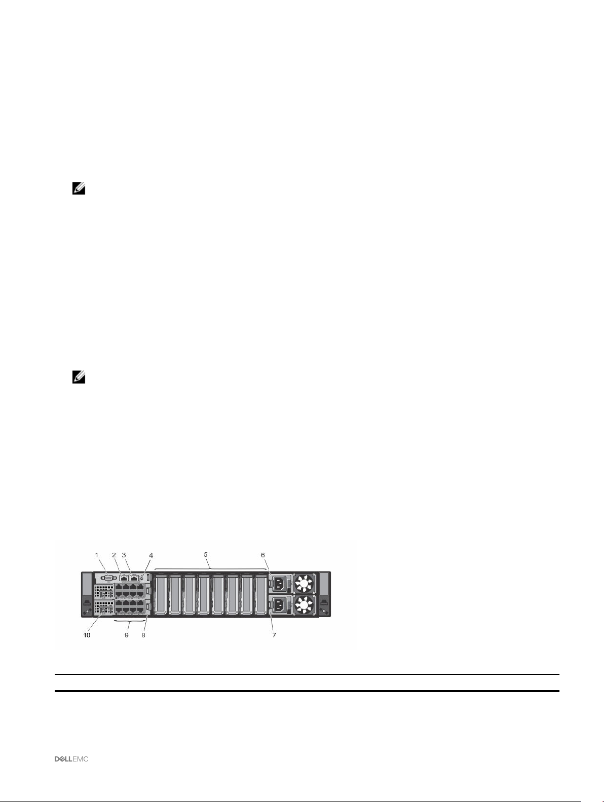
Chassis overview
A Back Panel view of the chassis is given here with a table that lists the parts and devices available in the CMC.
Figure 1.
Item
Indicator, Button, or Connector
1
2
Serial connector
Ethernet connector Gb1
13
Item Indicator, Button, or Connector
3
4
5
6
7
8
9
10
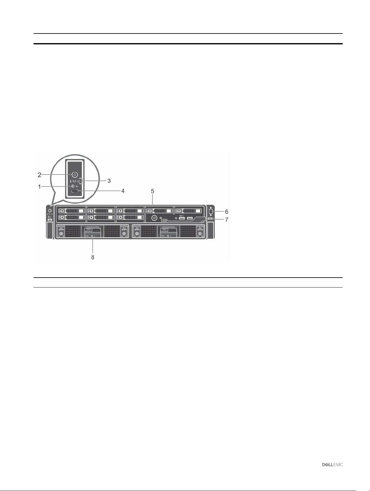
A Front Panel view of the chassis is given here with a table that lists the parts and devices available in the CMC.
Ethernet connector STK/Gb2 (stack)
System identification button
Low-profile PCIe expansion slots
Power supply (PSU1)
Power supply (PSU2)
I/O module (2)
I/O module ports
I/O module indicators
Figure 2.
Item
1
2
3
4
5
6
7
8
Indicator, Button, or Connector
System identification button
Enclosure power-on indicator, power button
Diagnostic indicators
KVM select button
Compute sled
Video connector
USB connector
Storage sled
Supported remote access connections
The following table lists the supported remote access connections.
14

Table 1. Supported remote access connections
Connection Features
CMC Network Interface ports
Serial port
• Gb ports: Dedicated network interface for the CMC web interface. The CMC has two
RJ-45 Ethernet ports:
– Gb1 (the uplink port)
– Gb2 (the stacking or cable consolidation port). The STK/Gb2 port can also be used
for CMC NIC failover.
NOTE: Ensure that the CMC setting is changed from default Stacking to
Redundant to implement NIC failover.
CAUTION: Connecting the STK/Gb2 port to the management network will
have unpredictable results if the CMC setting is not changed from default
Stacking to Redundant, to implement NIC failover. In the default Stacking
mode, cabling the Gb1 and STK/Gb2 ports to the same network
(broadcast domain) can cause a broadcast storm. A broadcast storm can
also occur if the CMC setting is changed to Redundant mode, but the
cabling is daisy chained between chassis in the Stacking mode. Ensure
that the cabling model matches the CMC setting for the intended usage.
• DHCP support.
• SNMP traps and e-mail event notification.
• Network interface for the iDRAC and I/O Modules (IOMs).
• Support for Telnet/SSH command console and RACADM CLI commands including
system boot, reset, power-on, and shutdown commands.
• Support for serial console and RACADM CLI commands including system boot, reset,
power-on, and shutdown commands.
• Support for binary interchange for applications specifically designed to communicate
with a binary protocol to a particular type of IOM.
• Serial port can be connected internally to the serial console of a server, or I/O module,
using the connect (or racadm connect) command.
Supported platforms
The CMC supports the PowerEdge FX2 and FX2s chassis models. The supported platforms are PowerEdge FC630, PowerEdge
FM120x4, and PowerEdge FC830. For information about compatibility with CMC, see the documentation for your device.
For the latest supported platforms, see the Dell Chassis Management Controller (CMC) Version 1.4 for Dell PowerEdge FX2/FX2s
Release Notes available at dell.com/support/manuals.
Supported web browsers
For the latest information about supported web browsers, see the Dell Chassis Management Controller (CMC) Version 1.4 for Dell
PowerEdge FX2/FX2s Release Notes at dell.com/support/manuals.
• Microsoft Internet Explorer 9
• Microsoft Internet Explorer 10
• Microsoft Internet Explorer 11
• Microsoft EDGE
• Safari version 7.1
• Safari version 8.0
• Mozilla Firefox version 40
• Mozilla Firefox version 41
• Google Chrome version 49
• Google Chrome version 50
15

NOTE: By default, TLS 1.1 and TLS 1.2 are supported in this release. However, to enable TLS 1.0 use the following
racadm command:
$ racadm config -g cfgRacTuning -o cfgRacTuneTLSProtocolVersionEnable TLSv1.0+
Supported firmware versions
The following table lists the firmware versions for BIOS, iDRAC, and Lifecycle Controller that support the servers listed:
Table 2. Latest Firmware Versions for BIOS, iDRAC, and Lifecycle Controller
Servers BIOS iDRAC Lifecycle Controller
PowerEdge FC830 2.2.5 2.40.40.40 2.40.40.40
PowerEdgeFC630 2.2.5 2.40.40.40 2.40.40.40
PowerEdgeFC430 2.2.5 2.40.40.40 2.40.40.40
PowerEdgeFM120 1.5 2.40.40.40 2.40.40.40
Supported Firmware Versions for Server Component Update
The following table lists the supported firmware versions for server components when CMC PowerEdge FX2/FX2s firmware is
updated from 1.3 to 1.4 version but the server components are not updated to the next version.
Table 3. Supported Server Component Versions for Server Component Update to N version
Platform Server Component Previous Component Version
(N-1 Version)
FD332 WN0HC 25.3.0.0016
FC430 iDRAC 2.20.20.20
Lifecycle Controller 2.20.20.20
Diagnostics 4239A19
BIOS 1.1.5
FC630 iDRAC 2.20.20.20
Lifecycle Controller 2.20.20.20
Diagnostics 4239A17
BIOS 1.2.5
FC830 iDRAC 2.20.20.20
Lifecycle Controller 2.20.20.20
Diagnostics 4239A20
BIOS 1.2.0
FM120x4 iDRAC 2.20.20.20
Lifecycle Controller 2.20.20.20
Diagnostics 4247A0
BIOS 1.3.0
Updated Component Version
(N Version)
25.4.1.0004
2.40.40.40
2.40.40.40
4239A33
2.2.5
2.40.40.40
2.40.40.40
4239A33
2.2.5
2.40.40.40
2.40.40.40
4239A33
2.2.5
2.40.40.40
2.40.40.40
4247A1
1.5
Supported Network Adapters
The following table lists the supported network adapters for PowerEdge FX2/FX2s.
16

Table 4. Supported network adapters PowerEdge FX2/FX2s
Platforms
Model FC420 FC620 FC430 FC630 FC830
5718 DP 1G No N/A Yes Yes No
57810S 10G SFP+ Yes Yes No Yes No
57810S 10G BASE-T Yes Yes No Yes No
5719 QP 1G Yes Yes Yes Yes Yes
LightPulse LPE12002 FC8 HBA Yes Yes Yes Yes Yes
LightPulse LPe15002B-M8–D DP 8G Gen 5No No Yes Yes Yes
LPe16002 Dual Port FC 16 HBA No No Yes Yes Yes
LighPulse LPE12000 FC 8 HBA Yes Yes No Yes Yes
LightPulse LPe 15000B-M8–D SP 8G
Gen 5
LPE 16000 Single Port FC 16 HBA No No No Yes Yes
OCe 14102–UX-D 10GbE CNA Yes Yes No No No
OCe 14102–U1–D 10GbE CNA No No Yes Yes Yes
OCe 14102–U1–D 10GbE CNA No No Yes Yes Yes
X540 DP 10G BASE-T Yes Yes Yes Yes Yes
i350 DP 1G No No Yes Yes Yes
i350 QP 1G Yes Yes Yes Yes Yes
X520 DP 10G SFP+ Yes Yes No Yes No
X710 DP 10GBE SFP+ (Fortville) No No Yes Yes Yes
CX3 DP 40GbE QSFP+ No No Yes Yes Yes
CX3 DP 10GbE DA/SFP+ No No Yes Yes Yes
CX3 MCX354–A-FCBT Yes Yes No No No
QLE2560 FC8 Single HBA Yes Yes No Yes Yes
578 10S 10G BASE-T Yes Yes Yes Yes Yes
QLE2660 SP FC 16 HBA No No No Yes Yes
QLE2662 DP FC16 HBA No No Yes Yes Yes
No No No Yes Yes
Managing licenses
The CMC features are available based on the license (CMC Express or CMC Enterprise) purchased. Only licensed features are
available in the interfaces that allow you to configure or use CMC. For example, CMC web interface, RACADM, WS-MAN, and so
on. CMC license management and firmware update functionality is always available through CMC web interface and RACADM.
Storage sled licenses
You can also purchase storage sled licenses to manage RAID controllers in CMC. The storage sled licenses can be installed at the
factory or purchased online. Following are the supported storage sled license types:
• One RAID controller and one HBA controller (RAID/HBA)
• Both RAID controllers
17

Storage sled licenses can be used for one or two RAID controllers. If a license is assigned to RAID on a single controller, the license is
applicable only to the first controller. Deleting a storage sled license may result in loss of RAID data.
Storage sled licenses are specific to a storage sled and are associated to the Service Tag of the storage sled. For example, if you
move a storage sled from one chassis to another, the license is also moved along with the storage sled. The master copies of
storage sled licenses are stored in the persistent store. For more information, see the Dell Chassis Management Controller for
PowerEdge FX2/FX2s RACADM Command Line Reference Guide available at dell.com/support/manuals.
The log messages for all storage sled license activities are stored in the CMC log file.
NOTE: Storage sled licenses are required to change the FD33xS and FD33xD RAID controllers from HBA mode to RAID
mode.
Types of licenses
The types of licenses offered are:
• 30–day evaluation and extension — The license expires after 30 days that can be extended for 30 days. Evaluation licenses are
duration-based, and the timer runs when power is applied to the system. These licenses are not applicable to storage sleds.
• Perpetual — The license is bound to the Service Tag and is permanent.
NOTE: Evaluation and site licenses are applicable only to CMC.
Acquiring licenses
Use any of the following methods to acquire the licenses:
• E-mail — License is attached to an e-mail that is sent after requesting it from the technical support center.
• Self-service portal — A link to the Self-Service Portal is available from CMC. Click this link to open the licensing Self-Service
Portal on the internet from where you can purchase licenses. For more information, see the online help for the self-service portal
page.
• Point-of-sale — License is acquired while placing the order for a system.
License operations
Before you perform the license management tasks, make sure to acquire the licenses. For more information, see the Acquiring
Licenses section and Overview and Feature Guide available at dell.com/support.
NOTE: If you have purchased a system with all the licenses pre-installed, then license management is not required.
You can perform the following licensing operations using CMC, RACADM, and WS-MAN for one-to-one license management, and
Dell License Manager for one-to-many license management:
• View — View the current license information for CMC and storage sleds.
• Import — After acquiring the license, store the license in a local storage and import it into CMC using one of the supported
interfaces. The license is imported if it passes the validation checks.
NOTE: For a few features, a CMC restart may be required to enable the features.
You can also import licenses for storage sleds that are installed in a chassis and when the storage sleds are powered off. If a
storage sled is already licensed, delete the existing license before importing a new one. The imported license is stored in the
CMC license manager and storage sled persistent store. The licensed features are available only if the RAID is reset when the
host server is rebooted. You can import storage sled licenses only to the targeted device.
• Export — Export the installed license into an external storage device backup or to reinstall it after a service part is replaced. The
file name and format of the exported license is <EntitlementID>.xml
• Delete — Delete the license that is assigned to a component or storage sled if the component or storage sled is missing. After
the license is deleted, it is not stored in CMC and the base product functions are enabled.
You can delete storage sled licenses only when the storage sled is powered off. Deleted licenses are removed from the storage
sled persistent store and the License Manager.
• Replace — Replace the license to extend an evaluation license, change a license type such as an evaluation license with a
purchased license, or extend an expired license.
18

For storage sleds, the new license overwrites the existing license in the CMC license manager and the storage sled persistent
store. Power off the storage sleds before replacing the license. The licensed features are available only after the RAID controller
is reset at the next host reboot.
• An evaluation license may be replaced with an upgraded evaluation license or with a purchased license.
• A purchased license may be replaced with an updated license or with an upgraded license. For more information, see Dell
Software License Management Portal available at WWW.DELL.COM/SUPPORT/LICENSING/US/EN/19
• Learn More — Learn more about an installed license, or the licenses available for a component installed in the server.
NOTE: For the Learn More option to display the correct page, make sure that *.dell.com is added to the list of
Trusted Sites in the Security Settings. For more information, see the Internet Explorer help documentation.
NOTE: If you try to install the PowerEdge FM120x4 license on PowerEdge FC630, the license installation fails. For
more information on licensing refer
Integrated Dell Remote Access Controller (iDRAC) User’s Guide
.
Licensable features in CMC
A list of CMC features that are enabled on the basis of your license is given here in the table.
Feature Express Enterprise
CMC Network Yes Yes
CMC Serial Port Yes Yes
RACADM (SSH, Local, and Remote) Yes Yes
WS-MAN Yes Yes
SNMP Yes Yes
Telnet Yes Yes
SSH Yes Yes
Web-based Interface Yes Yes
Email Alerts Yes Yes
CMC Settings Backup No Yes
CMC Settings Restore Yes Yes
Remote Syslog No Yes
Directory Services No Yes
Single Sign-On Support No Yes
Two-Factor Authentication No Yes
PK Authentication No Yes
Remote File Share No Yes
Enclosure level power capping No Yes
Multi-chassis management No Yes
FlexAddress Enablement No Yes
One-to-many Server Firware Update No Yes
One-to-many configuration for iDRAC No Yes
License component state or condition and available operations
The following table provides the list of license operations available based on the license state or condition.
Table 1. License Operations Based on State and Condition
19

License/Component
state or condition
Non-administrator login No Yes No No Yes
Active license Yes Yes Yes Yes Yes
Expired license No Yes Yes Yes Yes
License installed but
component missing
Import Export Delete Replace Learn More
No Yes Yes No Yes
Viewing localized versions of the CMC web interface
To view localized versions of the CMC web interface, read through your web browser's documentations. To view the localized
versions, set the browser to the desired language.
Supported management console applications
The CMC supports integration with Dell OpenManage Console. For more information, see the OpenManage Console documentation
available at dell.com/support/manuals.
How to use this User's Guide
The contents of this User's Guide enable you to perform the tasks by using:
• The Web interface: Only the task-related information is given here. For information about the fields and options, see the CMC
for Dell PowerEdge FX2/FX2s Online Help that you can open from the Web interface.
• The RACADM commands: The RACADM command or the object that you must use is provided here. For more information
about a RACADM command, see the Dell Chassis Management Controller for PowerEdge FX2/FX2s RACADM Command Line
Reference Guide available at dell.com/support/manuals.
Other documents you may need
To access the documents from the Dell Support site. Along with this Reference Guide, you can access the following guides available
at dell.com/support/manuals.
• The CMC FX2/FX2s Online Help provides information about using the web interface. To access the Online Help, click Help on
the CMC web interface.
• The Chassis Management Controller Version 1.4 for Dell PowerEdge FX2/FX2s RACADM Command Line Reference Guide
provides information about using the FX2/FX2s–related RACADM features.
• The Dell Chassis Management Controller (CMC) for Dell PowerEdge FX2/FX2s Version 1.4 Release Notes, available at
dell.com/cmcmanuals, provides last-minute updates to the system or documentation or advanced technical reference material
intended for experienced users or technicians.
• The Integrated Dell Remote Access Controller 8 (iDRAC) User’s Guide provides information about installation, configuration, and
maintenance of the iDRAC8 on managed systems.
• The Dell OpenManage Server Administrator’s User’s Guide provides information about installing and using Server Administrator.
• The Dell OpenManage SNMP Reference Guide for iDRAC and Chassis Management Controller provides information about
SNMP MIBs.
• The Dell Update Packages User's Guide provides information about obtaining and using Dell Update Packages as part of your
system update strategy.
• Dell systems management application documentation provides information about installing and using the systems management
software.
The following system documents provide more information about the system in which CMC PowerEdge FX2/FX2s is installed:
• The safety instructions that came with your system provide important safety and regulatory information. For additional
regulatory information, see the Regulatory Compliance home page at www.dell.com/regulatory_compliance. Warranty
information may be included within this document or as a separate document.
20

• The setup placemat shipped with your system provides information about the initial system setup and configuration.
• The server module's Owner's Manual provides information about the server module's features and describes how to
troubleshoot the server module and install or replace the server module's components. This document is available online at
dell.com/poweredgemanuals.
• The rack documentation included with your rack solution describes how to install your system into a rack, if required.
• For the full name of an abbreviation or acronym used in this document, see the Glossary at dell.com/support/manuals.
• Systems management software documentation describes the features, requirements, installation, and basic operation of the
software.
• Documentation for any components you purchased separately provides information to configure and install these options.
• Any media that ships with your system that provides documentation and tools for configuring and managing your system,
including those pertaining to the operating system, system management software, system updates, and system components
that you purchased with your system. For more information on the system, scan the Quick Resource Locator (QRL) available on
your system and the system setup placemat that shipped with your system. Download the QRL application from your mobile
platform to enable the application on your mobile device.
Accessing documents from Dell support site
You can access the required documents in one of the following ways:
• Using the following links:
– For all Enterprise Systems Management documents — Dell.com/SoftwareSecurityManuals
– For OpenManage documents — Dell.com/OpenManageManuals
– For Remote Enterprise Systems Management documents — Dell.com/esmmanuals
– For iDRAC and Lifecycle Controller documents — Dell.com/idracmanuals
– For OpenManage Connections Enterprise Systems Management documents — Dell.com/
OMConnectionsEnterpriseSystemsManagement
– For Serviceability Tools documents — Dell.com/ServiceabilityTools
– For Client Command Suite Systems Management documents — Dell.com/DellClientCommandSuiteManuals
• From the Dell Support site:
a. Go to Dell.com/Support/Home.
b. Under Select a product section, click Software & Security.
c. In the Software & Security group box, click the required link from the following:
– Enterprise Systems Management
– Remote Enterprise Systems Management
– Serviceability Tools
– Dell Client Command Suite
– Connections Client Systems Management
d. To view a document, click the required product version.
• Using search engines:
– Type the name and version of the document in the search box.
21

2
Installing and setting up CMC
This section provides information about how to install your CMC hardware, establish access to CMC, configure your management
environment to use CMC, and guides you through the tasks for configuring a CMC:
• Set up initial access to CMC.
• Access CMC through a network.
• Add and configure CMC users.
• Update CMC firmware.
Installing CMC hardware
The CMC is pre-installed on your chassis and hence no installation is required.
Checklist to set up chassis
The following tasks enable you to accurately setup the chassis:
1. The CMC and the management station, where you use your browser, must be on the same network, which is called the
management network. Connect an Ethernet network cable from the port labelled GB1 to the management network.
Management Network: CMC and the iDRAC (on each server) and the network management ports for the switch I/O module
are connected to a common internal network in the PowerEdge FX2/FX2s chassis. This allows the management network to be
isolated from the server data network.
Application Network: Access to the managed servers is accomplished through network connections to the I/O module (IOM).
This allows the application network to be isolated from the management network. It is important to separate this traffic for
uninterrupted access to chassis management.
NOTE: It is recommended to isolate chassis management from the data network. Due to the potential of traffic on
the data network, the management interfaces on the internal management network can be saturated by traffic
intended for servers. This results in CMC and iDRAC communication delays. These delays may cause unpredictable
chassis behavior, such as CMC displaying iDRAC as offline even when it is up and running, which in turn causes
other unwanted behavior. If physically isolating the management network is impractical, the other option is to
separate CMC and iDRAC traffic to a separate VLAN. CMC and individual iDRAC network interfaces can be
configured to use a VLAN.
2. The STK/Gb2 port can also be used for CMC NIC failover. Ensure that the CMC setting is changed from default Stacking to
Redundant to implement NIC failover. For more information, see Configuring Management Port 2
CAUTION: Connecting the STK/Gb2 port to the management network will have unpredictable results if the CMC
setting is not changed from default Stacking to Redundant, to implement NIC failover. In the default Stacking
mode, cabling the Gb1 and STK/Gb2 ports to the same network (broadcast domain) can cause a broadcast storm.
A broadcast storm can also occur if the CMC setting is changed to Redundant mode, but the cabling is daisy
chained between chassis in the Stacking mode. Ensure that the cabling model matches the CMC setting for the
intended usage.
3. Install the I/O module in the chassis and connect the network cable to the I/O module.
4. Insert the servers in the chassis.
5. Connect the chassis to the power source.
6. To power on the chassis, press the power button or use the following interfaces after completing the task 6. Using the Web
interface, go to
22
Chassis Overview → Power → Control → Power Control Options → Power On System. Click Apply.

You can also power on the chassis using the command line interface, use racadm chassisaction powerup command to
accomplish it.
NOTE: Do not turn on the servers.
7. The default CMC network configuration is Static with the CMC IP address 192.168.0.120. If you want to change the network
configuration to DHCP, connect a serial cable to serial port on the CMC. For more information on serial connection, refer to
Serial interface/protocol setup in Using Remote Access Software From a Management Station section.
After the serial connection is established, login and use the command racadm setniccfg —d to change the network
configuration to DHCP. CMC takes 30 to 60 seconds approximately to obtain the IP address from the DHCP server.
To view the DHCP assigned CMC IP address, use one of the following methods:
• To view CMC IP address using serial connection with CMC, perform the following steps:
1. Connect one end of the serial null modem cable to the serial connector on the back of the chassis.
2. Connect the other end of the cable to the management system serial port.
3. After the connection is established, login to CMC using default root account credentials.
4. Run the racadm getniccfg command.
In the output displayed, search for Current IP Address.
• To view CMC IP address by connecting the server using KVM, perform the following steps:
1. Connect to a server in the chassis using KVM.
NOTE: For more details on how to connect a server through KVM, see Accessing Server Using KVM.
2. Turn on the server.
3. Make sure the server is set to boot in Unified Extensible Firmware Interface (UEFI) mode.
4. Press F2 to access the System Setup page.
5. In the System Setup page, click iDRAC Settings → System Summary.
The CMC IP address is displayed in the Chassis Management Controller section.
For more information about iDRAC Settings page in the iDRAC GUI, see the Dell Integrated Dell Remote Access
Controller (iDRAC) User’s Guide .
8. Connect to the CMC IP address by using a web browser by typing the default root account credential.
9. Configure iDRAC network settings as required. by default, iDRAC LAN is enabled with static IP configured. To determine the
default static IP address with an
static IP address with an Express license. Go to Server Overview → Server-Slot → Setup → iDRAC.
10. Provide the IO module with an external management IP address(if applicable) in the CMC web interface. You can get the IP
address by clicking I/O Module Overview, and then clicking Setup.
11. Connect to each iDRAC through the web interface using default root account credential to complete any necessary
configuration.
12. Turn on the servers and install the operating system.
Enterprise license, go to Server Overview → Setup → iDRAC. You can also determine the
NOTE: The default local account credential is root (user name) and calvin (user password).
Daisy chain FX2 CMC network connection
If you have multiple chassis in a rack, you can reduce the number of connections to the management network by daisy-chaining up
to ten chassis together. You can reduce the number of management network uplink connections required from ten to one.
When daisy-chaining chassis together, GB is the uplink port and STK is the stacking (cable consolidation) port. Connect the Gb
ports to the management network or to the STK port of CMC in a chassis that is closer to the network. Connect the STK port only
to a Gb port further from the chain or network.
The following figure illustrates the arrangement of cables for four daisy-chained chassis, each with active CMCs.
23
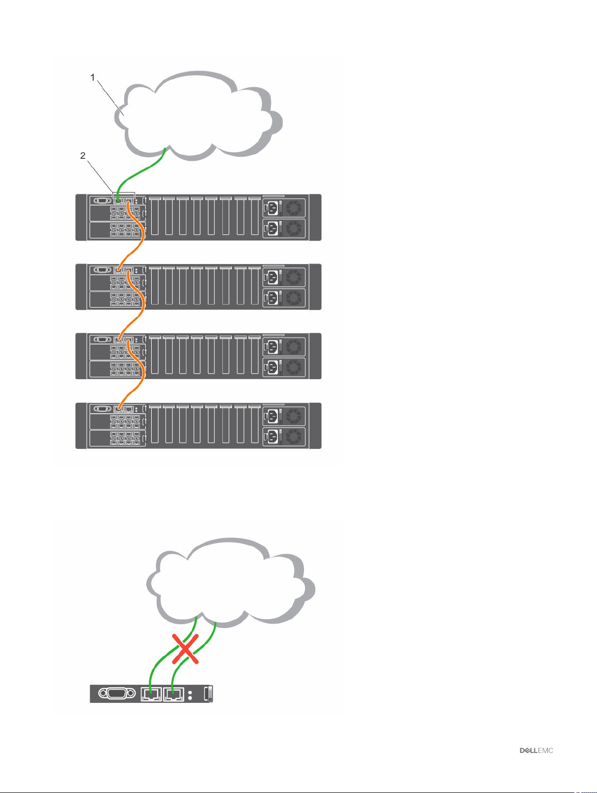
1 Management Network
2 Active CMC
The following figure illustrates an example of incorrect cabling of CMC in stacking mode.
24

Following are the steps to daisy-chain four FX2 CMC modules:
1. Connect the GB port of the FX2 CMC in the first chassis to the management network.
2. Connect the GB port of the FX2 CMC in the second chassis to the STK port of the FX2 CMC in the first chassis.
3. If you have a third chassis, connect the GB port of its FX2 CMC to the STK port of the FX2 CMC in the second chassis.
4. If you have a fourth chassis, connect the GB port of its FX2 CMC to the STK port of the FX2 CMC in the third chassis.
CAUTION: The STK port on any CMC must never be connected to the management network. It can only be connected
to the GB port on another chassis. Connecting a STK port to the management network can disrupt the network and
cause loss of data. Cabling GB and STK to the same network (broadcast domain) can cause a broadcast storm.
NOTE: Resetting a CMC whose STK port is chained to another CMC can disrupt the network for CMCs that appear later
in the chain. The child CMCs may log messages indicating that the network link is lost.
Using remote access software from a management station
You can access CMC from a management station using various remote access software. Here is a list of remote access softwares
by Dell which is available from your Operating System.
Table 5. CMC Interfaces
Interface/Protocol Description
Serial CMC supports a serial text console that can be launched using
any terminal emulation software. Following are couple of
examples of terminal emulation software that can be used to
connect to CMC.
• Linux Minicom
• Hilgraeve’s HyperTerminal for Windows
Connect one end of the serial null modem cable (present at both
ends) to the serial connector on the back of the chassis.
Connect the other end of the cable to management station
serial port. For more information on connecting cables, refer to
the back panel of the chassis in Chassis Overview section.
Configure your terminal emulation software with the following
parameters:
• Baud rate: 115200
• Port: COM1
• Data: 8 bit
• Parity: None
• Stop: 1 bit
• Hardware flow control: Yes
• Software flow control: No
Remote RACADM CLI Remote RACADM is a client utility that runs on a management
station. It uses the out-of-band network interface to run
RACADM commands on the managed system and uses the
HTTPs channel. The –r option runs the RACADM command
over a network, it requires CMC IP, username and password.
To use remote RACADM from your management station, install
remote RACADM using the Dell Systems Management Tools
and Documentation DVD that is available with your system. For
more information on Remote RACADM
Web Interface Provides remote access to CMC using a graphical user
interface. The Web interface is built into the CMC firmware and
is accessed through the NIC interface from a supported web
25

browser on the management station. For a list of supported
Web browsers, see the Supported Browsers section in the Dell
System Software Support Matrix at dell.com/support/
manuals.
Telnet Provides command line access to CMC through the network.
The RACADM command line interface and the connect
command, which is used to connect to the serial console of a
server or IO module, are available from the CMC command line.
NOTE: Telnet is not a secure protocol and is disabled by
default. Telnet transmits all data, including passwords in
plain text.
SNMP Simple Network Management Protocol (SNMP) is a set of
protocol definitions for managing devices on the networks. The
CMC provides access to SNMP, which allows you to use SNMP
tools to query the CMC for Systems Management information.
The CMC MIB file can be downloaded from the CMC Web
interface, go to Chassis Overview → Network → Services →
SNMP. See the Dell OpenManage SNMP Reference Guide for
more information about the CMC MIB.
The following example show how the net-snmp snmpget
command can be used to get the chassis service tag from the
CMC.
snmpget -v 1 -c <CMC community name> <CMC IP
address>.1.3.6.1.4.1.674.10892.2.1.1.6.0
WSMan The WSMan Services is based on the Web Services for
Management (WSMan) protocol to perform one-to-many
systems management tasks. You can use WSMan client such as
WinRM client (Windows) or the OpenWSMan client (Linux) to
use the LC-Remote Services functionality. You can also use
Power Shell and Python script the WSMan interface.
WSMan is a Simple Object Access Protocol (SOAP)–based
protocol used for systems management. CMC uses WS–
Management to convey Distributed Management Task Force
(DMTF) Common Information Model (CIM)–based
management information. The CIM information defines the
semantics and information types that can be modified in a
managed system.
The CMC WSMan implementation uses SSL on port 443 for
transport security, and supports basic authentication. The data
available through WS-Management is provided by CMC
instrumentation interface mapped to the DMTF profiles and
extension profiles.
NOTE: The SSL port used for transport security is the
same as the CMC HTTPS port.
For more information, see:
26
• MOFs and Profiles — delltechcenter.com/page/
DCIM.Library
• DTMF Web site — dmtf.org/standards/profiles/
• WSMan Release notes file.
• www.wbemsolutions.com/ws_management.html
• DMTF WS-Management Specifications: www.dmtf.org/
standards/wbem/wsman
For client connection using Microsoft WinRM, the minimum
required version is 2.0. For more information, refer to the
Microsoft article, <support.microsoft.com/kb/968929>.

Launching CMC using other systems management tools
You can also launch CMC from the Dell Server Administrator or Dell OpenManage Essentials.
To access CMC interface using Dell Server Administrator, launch Server Administrator on your management station. In the left pane
of the Server Administrator home page, click System → Main System Chassis → Remote Access Controller. For more
information, see the
Dell Server Administrator User’s Guide at dell.com/support/manuals.
Remote RACADM installation
To use remote RACADM from your management station, install remote RACADM using the Dell Systems Management Tools and
Documentation DVD that is available with your system. This DVD includes the following Dell OpenManage components:
• DVD root — Contains the Dell Systems Build and Update Utility.
• SYSMGMT — Contains the systems management software products including Dell OpenManage Server Administrator.
• Docs — Contains documentation for systems, systems management software products, peripherals, and RAID controllers.
• SERVICE — Contains the tools required to configure your system, and delivers the latest diagnostics and Dell-optimized drivers
for your system.
For information about installing Dell OpenManage software components, see the Dell OpenManage Installation and Security User's
Guide available at dell.com/support/manuals. You can also download the latest version of the Dell DRAC Tools from
support.dell.com.
Installing remote RACADM on a Windows management station
If you are using the DVD, run
If you have downloaded the software from support.dell.com:
1. Extract the downloaded file and execute the .msi file provided.
Depending on the version downloaded, the file will be named DRAC.msi, RACTools.msi, or RACTools64Bit.msi.
2. Accept the license agreement. Click Next.
3. Select the location where it is to be installed. Click Next.
4. Click Install.
The installing window appears.
5. Click Finish.
Open an administrative command prompt, type racadm and press Enter. If you get the RACADM help instructions, it implies that
the software is installed correctly.
<path>
\SYSMGMT\ManagementStation\windows\DRAC\
<.msi file name>
Installing remote RACADM on a Linux management station
1. Log in as root to the system running a supported Red Hat Enterprise Linux or SUSE Linux Enterprise Server operating system
where you want to install the managed system components.
2. Insert the Dell Systems Management Tools and Documentation DVD into the DVD drive.
3. To mount the DVD to a required location, use the mount command or a similar command.
NOTE: On the Red Hat Enterprise Linux 5 operating system, DVDs are auto-mounted with the -noexec mount
option. This option does not allow you to run any executable from the DVD. You need to mount the DVD-ROM
manually, and then run the commands.
4. Navigate to the SYSMGMT/ManagementStation/linux/rac directory. To install the RAC software, type the following
command:
rpm -ivh *.rpm
5. For help about the RACADM command, type racadm help after you run the previous commands. For more information
about RACADM, see the
Guide.
Chassis Management Controller for Dell PowerEdge FX2/FX2s RACADM Command Line Reference
27

NOTE: When using the RACADM remote capability, you must have the 'write' permission on the folders where you
are using the RACADM subcommands, involving the file operations. For example, racadm getconfig -f <file
name>.
Uninstalling remote RACADM from a Linux management station
1. Log in as root to the system where you want to uninstall the management station features.
2. Run the following rpm query command to determine which version of the DRAC tools is installed:
rpm -qa | grep mgmtst-racadm
Verify the package version to be uninstalled and uninstall the feature by using the rpm -e rpm -qa | grep mgmtst-
3.
racadm
command.
Configuring a web browser
You can configure and manage CMC, servers, and modules installed in the chassis through a web browser. See the “Supported
Browsers" section in the Dell Systems Software Support Matrix at dell.com/support/manuals.
The CMC and the management station where you use your browser must be on the same network, which is called the management
network. On the basis of your security requirements, the management network can be an isolated and highly secure network.
NOTE: Make sure that the security measures on the management network such as firewalls and proxy servers, do not
prevent your web browser from accessing the CMC.
Some browser features can interfere with connectivity or performance, especially if the management network does not have a
route to the Internet. If your management station is running on a Windows operating system, some Internet Explorer settings can
interfere with connectivity, even though you use a command line interface to access the management network.
NOTE: To address security issues, Microsoft Internet Explorer strictly monitors the time on its cookie management. To
support this, the time on your computer that runs Internet Explorer must be synchronized with the time on the CMC.
Proxy server
To browse through a proxy server that does not have access to the management network, you can add the management network
addresses to the exception list of the browser. This instructs the browser to bypass the proxy server while accessing the
management network.
Microsoft phishing filter
If the Microsoft Phishing Filter is enabled in Internet Explorer on your management system, and your CMC does not have Internet
access, accessing CMC may be delayed by a few seconds. This delay can happen if you are using the browser or another interface
such as remote RACADM. To disable the phishing filter:
1. Start Internet Explorer.
2. Click Tools → Phishing Filter, and then click Phishing Filter Settings.
3. Select the Disable Phishing Filter option and click OK.
Downloading files from CMC with Internet Explorer
When you use Internet Explorer to download files from the CMC, you may experience problems when the Do not save encrypted
pages to disk option is not enabled.
To enable the Do not save encrypted pages to disk option:
1. Start Internet Explorer.
2. Click Tools → Internet Options → Advanced.
3. In the Security section, select the Do not save encrypted pages to disk option.
Enabling animations in Internet Explorer
When transferring files to and from the web interface, a file transfer icon spins to show transfer activity. While using Internet
explorer, you have to configure the browser to play animations.
28

To configure Internet Explorer to play animations:
1. Start Internet Explorer.
2.
Click Tools → Internet Options → Advanced.
3. Go to the Multimedia section, and then select the Play animations in web pages option.
Downloading and updating CMC firmware
To download the CMC firmware, see Downloading CMC Firmware.
To update the CMC firmware, see Updating CMC Firmware.
Setting chassis physical location and chassis name
You can set the chassis location in a data center and the chassis name to identify the chassis on the network (default name is cmc“Service Tag”). For example, an SNMP query on the chassis name returns the name you configure.
Setting chassis physical location and chassis name using web interface
To set the chassis location and chassis name using the CMC web interface:
1. In the left pane, go to Chassis Overview, and then click Setup.
2. On the General Chassis Settings page, type the location properties and the chassis name. For more information about setting
chassis properties, see the CMC Online Help.
NOTE: The Chassis Location field is optional. It is recommended to use the Data Center, Aisle, Rack, and Rack Slot
fields to indicate the physical location of the chassis.
3. Click Apply. The settings are saved.
Setting chassis physical location and chassis name using RACADM
To set the chassis name, location, date, and time by using the command line interface, see the setsysinfo and setchassisname
commands.
For example racadm setsysinfo —c chassisname or racadm setsysinfo —c chassislocation
For more information, see the Chassis Management Controller for PowerEdge FX2/FX2s RACADM Command Line Reference
Guide.
Setting date and time on CMC
You can manually set the date and time, or you can synchronize the date and time with a Network Time Protocol (NTP) server.
Setting date and time on CMC using CMC web interface
To set the date and time on CMC:
1. In the left pane, click Chassis Overview → Setup → Date/Time.
2. To synchronize the date and time with a Network Time Protocol (NTP) server, on the Date/Time page, select Enable NTP
and specify up to three NTP servers. To manually set the date and time, clear the Enable NTP option, and then edit the Date
and Time fields.
3. Select the Time Zone from the drop-down menu, and then click Apply.
Setting date and time on CMC using RACADM
To set the date and time using the command line interface, see the config command and cfgRemoteHosts database property
group sections in the Chassis Management Controller for PowerEdge FX2/FX2s RACADM Command Line Reference Guide
available at dell.com/support/manuals.
For example racadm setractime -l 20140207111030.
To read the date and time use racadm getractime command.
29

Configuring LEDs to identify components on the chassis
You can enable the LEDs of components (chassis, servers, storage sleds, and I/O Modules) to blink so that you can identify the
component on the chassis.
NOTE: To modify these settings, you must have the Debug Administrator privilege on a CMC.
When a compute sled is performing an identify action, the front LED of the connected storage sled also flashes the identify pattern.
If a storage sled is in split-single mode and is connected to two compute nodes, it shall flash the identify pattern if either of the two
compute nodes is performing an identify action.
If you start an identify action using OMSS or iDRAC for a compute sled, drive or enclosure, the storage sled associated with them
also performs the identify action.
NOTE: You cannot select only storage sleds for an identify action.
Configuring LED blinking using CMC web interface
To enable blinking for one, multiple, or all component LEDs:
• In the left pane, go to any of the following pages:
– Chassis Overview → Troubleshooting.
– Chassis Overview → Chassis Controller → Troubleshooting.
– Chassis Overview → Server Overview → Troubleshooting.
NOTE: Only servers can be selected on this page.
To enable blinking of a component LED, select the respective component , and then click Blink. To disable blinking of a component
LED, deselect the server, and then click Unblink.
Configuring LED blinking using RACADM
Open a serial/Telnet/SSH text console to CMC, log in, and type:
racadm setled -m <module> [-l <ledState>], where <module> specifies the module whose LED you want to
configure. Configuration options:
• server-n where n = 1-4 (PowerEdge FM120x4), and server-nx where n = 1–4 and x = a to b (PowerEdge FC630).
• switch-1
• cmc-active
and <ledState> specifies whether or not the LED should blink. Configuration options:
• 0 — not blinking (default)
• 1 — blinking
Configuring CMC properties
You can configure CMC properties such as power budgeting, network settings, users, and SNMP and email alerts using the web
interface or RACADM commands.
Configuring front panel
You can use the front panel page to configure:
• Power button
• KVM
30

Configuring power button
To configure the chassis power button:
1.
In the left pane, click Chassis Overview → Front Panel → Setup.
2. On the Front Panel Configuration page, under the Power Button Configuration section, select the Disable Chassis Power
option, and then click Apply.
Button
The chassis power button is disabled.
Accessing a server using KVM
To map a Server to KVM from web interface:
1. Connect a monitor to the video connector and a keyboard to USB connector located on the front of the chassis.
2. In the left pane, click Chassis Overview → Front Panel → Setup.
3. On the Front Panel Configuration page, under the KVM Configuration section, select Enable KVM Mapping option.
4. On the Front Panel Configuration page, under the KVM Configuration section, for KVM Mapped option, select the desired
server from the drop down list.
5. Click Apply.
To map a Server to KVM using racadm, useracadm config -g cfgKVMInfo -o cfgKvmMapping [server slot #]
command.
To view the current KVM mapping using racadm, use racadm getconfig -g cfgKVMInfo.
Configuring chassis management at server mode
This feature allows you to manage and monitor the chassis shared components and chassis nodes as rack servers. When this
feature is enabled, you can use the iDRAC RACADM proxy, blade server operating systems and Lifecycle Controller to do the
following:
• Monitor and manage chassis fans, power supplies, temperature sensors
• Update and configure the CMC firmware
Configuring chassis management at server using CMC web interface
To enable chassis management at server mode:
1. In the left pane, click Chassis Overview → Setup → General.
2. In the General Chassis Settings page, from the Chassis Management at Server Mode drop-down, select one of the following
modes:
• None — This mode does not enable you to monitor or manage the chassis component through iDRAC, OS, or Lifecycle
Controller.
• Monitor — This mode enables you to monitor the chassis components but you cannot perform any firmware update
through iDRAC, OS, iDRAC RACADM proxy, or Lifecycle Controller.
• Manage and Monitor — This mode enables you to monitor the chassis components and update the CMC firmware using
DUP through iDRAC, OS, iDRAC RACADM, or Lifecycle Controller.
Configuring chassis management at server mode using RACADM
To enable the Chassis Management at server using RACADM, use the following commands:
• To disable Chassis Management at Server mode, use:
racadm config –g cfgRacTuning – cfgRacTuneChassisMgmtAtServer 0
• To change Chassis Management at Server mode to monitor, use:
racadm config –g cfgRacTuning – cfgRacTuneChassisMgmtAtServer 1
31

• To change Chassis Management at server mode to manage and monitor, use:
racadm config –g cfgRacTuning – cfgRacTuneChassisMgmtAtServer 2
32

3
Logging into CMC
You can log in to CMC as a CMC local user, as a Microsoft Active Directory user, or as an LDAP user. You can also log in using
Single Sign-On or a Smart Card.
Configure public key authentication over SSH
You can configure up to six public keys that can be used with the service username over an SSH interface. Before adding or deleting
public keys, make sure to use the view command to see what keys are already set up, so that a key is not accidentally overwritten
or deleted. The service username is a special user account that can be used when accessing the CMC through SSH. When the PKA
over SSH is set up and used correctly, you need not enter username or passwords to log in to the CMC. This can be very useful to
set up automated scripts to perform various functions.
NOTE: There is no GUI support for managing this feature, you can use only the RACADM.
When adding new public keys, make sure that the existing keys are not already at the index, where the new key is added. CMC does
not perform checks to ensure previous keys are deleted before a new one is added. As soon as a new key is added, it is
automatically in effect as long as the SSH interface is enabled.
When using the public key comment section of the public key, remember that only the first 16 characters are utilized by the CMC.
The public key comment is used by the CMC to distinguish SSH users when using the RACADM getssninfo command, because
all the PKA users use the service username to log in.
For example, if two public keys are set up one with comment PC1 and one with comment PC2:
racadm getssninfo
Type User IP Address Login
Date/Time
SSH PC1 x.x.x.x 06/16/2009
09:00:00
SSH PC2 x.x.x.x 06/16/2009
09:00:00
For more information about the sshpkauth, see the Chassis Management Controller for PowerEdge FX2/FX2s Command Line
Reference Guide
.
Generating public keys for systems running Windows
Before adding an account, a public key is required from the system that accesses the CMC over SSH. There are two ways to
generate the public/private key pair: using PuTTY Key Generator application for clients running Windows or ssh-keygen CLI for
clients running Linux.
This section describes simple instructions to generate a public/private key pair for both applications. For additional or advanced
usage of these tools, see the application Help.
To use the PuTTY Key Generator to create a basic key for clients running Windows:
1. Start the application and select SSH-2 RSA for the type of key to generate (SSH-1 is not supported).
2. Enter the number of bits for the key. RSA key size should be between 768 and 4096.
NOTE:
• CMC may not display a message if you add keys less than 768 or greater than 4096, but when you try to log in with
these keys, it fails.
• CMC accepts RSA keys up to key strength 4096, but the recommended key strength is 1024.
33

3. Click Generate and move the mouse in the window as directed.
After the key is created, you can modify the key comment field.
You can also enter a passphrase to make the key secure. Ensure that you save the private key.
4. You have two options for using the public key:
• Save the public key to a file to upload later.
• Copy and paste the text from the Public key for pasting window when adding the account using the text option.
Generating public keys for systems running Linux
The ssh-keygen application for Linux clients is a command line tool with no graphical user interface. Open a terminal window and at
the shell prompt type:
ssh-keygen –t rsa –b 1024 –C testing
where,
–t must be rsa.
–b specifies the bit encryption size between 768 and 4096.
–c allows modifying the public key comment and is optional.
The < passphrase > is optional. After the command completes, use the public file to pass to the RACADM for uploading the file.
Accessing CMC web interface
Before you log in to CMC using the web interface, make sure that you have configured a Supported Web Browser and the user
account is created with the required privileges.
NOTE: If you are using Microsoft Internet Explorer, connect using a proxy, and if you see the error The XML page
cannot be displayed
, you must disable the proxy to continue.
To access the CMC web interface:
1. Open a web browser supported on your system.
For the latest information on supported web browsers, see the Dell Systems Software Support Matrix located at dell.com/
support/manuals.
2. In the Address field, type the following URL, and then press <Enter>:
• To access CMC using IPv4 address: https://<CMC IP address>
If the default HTTPS port number (port 443) was changed, type: https://<CMC IP address>:<port number>
• To access CMC using IPv6 address: https://[<CMC IP address>]
If the default HTTPS port number (port 443) was changed, type: https://[<CMC IP address>]:<port number>,
where <CMC IP address> is the IP address for CMC and <port number> is the HTTPS port number.
The CMC Login page appears.
NOTE: While using IPv6, you must enclose the CMC IP address in parenthesis ([ ]).
Logging into CMC as a local user, active directory user, or LDAP user
To log in to CMC, you must have a CMC account with the Log In to CMC privilege. The default root account is the default
administrative account that ships with CMC.
NOTE: For added security, it is recommended that you change the default password of the root account during initial
setup.
NOTE: When Certificate Validation is enabled, FQDN of the system should be provided. If certificate validation is
enabled and IP address is provided for the Domain Controller, then the login will fail.
CMC does not support extended ASCII characters, such as ß, å, é, ü, or other characters used primarily in non-English languages.
34

To log in as a local user, Active Directory user, or LDAP user.
1. In the Username field, type your user name:
• CMC user name: <user name>
NOTE: The CMC user name can contain only alphanumeric characters and certain special characters. The at
(@) symbol and following special characters are not supported:
– Forward slash (/)
– Backward slash (/)
– Semicolon (;)
– Backward Quote (`)
– Quotations (“)
• Active Directory user name: <domain>\<user name>, <domain>/<user name> or <user>@<domain>.
• LDAP user name: <user name>
NOTE: This field is case-sensitive.
2. In the Password field, type the user password.
NOTE: For Active Directory user, the Username field is case-sensitive.
3. In the Domain field, from the drop-down menu, select the required domain.
4. Optionally, select a session timeout. This is the duration for which you can stay logged in with no activity before you are
automatically logged out. The default value is the
5. Click OK.
You are logged into CMC with the required user privileges.
You cannot log in to the Web interface with different user names in multiple browser windows on a single workstation.
Web Service Idle Timeout.
NOTE: If LDAP authentication is enabled and you attempt logging into CMC using the local credentials, the credentials
are first checked in the LDAP server and then in CMC.
Logging into CMC using a smart card
To use this feature, you must have an Enterprise License. You can log in to CMC using a smart card. Smart cards provide Two
Factor Authentication (TFA) that provide two-layers of security:
• Physical smart card device.
• Secret code such as a password or PIN.
Users must verify their credentials using the smart card and the PIN.
NOTE: You cannot use the IP address to log in to CMC using the Smart Card login. Kerberos validates your credentials
based on the Fully Qualified Domain Name (FQDN).
Before you log in as an Active Directory user using a Smart Card, make sure to:
• Upload a Trusted Certificate Authority (CA) certificate (CA-signed Active Directory certificate) to CMC
• Configure the DNS server.
• Enable Active Directory login.
• Enable Smart Card login.
To log in to CMC as an Active Directory user using a smart card:
1. Log in to CMC using the link https://<cmcname.domain-name>.
The CMC Login page is displayed asking you to insert a smart card.
35

NOTE: If you changed the default HTTPS port number (port 80), access the CMC web page using
<cmcname.domain-name>:<port number>, where cmcname is the CMC host name for CMC,
the domain name, and
2. Insert the smart card and click Login.
The PIN dialog box is displayed.
3. Type the PIN and click Submit.
NOTE: If the smart card user is present in Active Directory, an Active Directory password is not required. Else, you
have to log in by using an appropriate username and password.
You are logged in to CMC with your Active Directory credentials.
port number
is the HTTPS port number.
domain-name
is
Logging into CMC using Single Sign-On
When Single Sign-On (SSO) is enabled, you can log in to CMC without providing your domain user authentication credentials, such
as user name and password. To use this feature, you must have an Enterprise License.
NOTE: You cannot use the IP address to log in to the SSO. Kerberos validates your credentials against the Fully Qualified
Domain Name (FQDN).
Before logging in to CMC using SSO, make sure that:
• You have logged in to your system using a valid Active Directory user account.
• Single Sign-On option is enabled during the Active Directory configuration.
To log in to CMC using SSO:
1. Log in to the client system using your network account.
2. Access the CMC web interface by using: https://<cmcname.domain-name>
For example, cmc-6G2WXF1.cmcad.lab,, where cmc-6G2WXF1 is the cmc-name and cmcad.lab is the domain name.
NOTE: If you have changed the default HTTPS port number (port 80), access the CMC web interface using
<cmcname.domain-name>:<port number>, where the
name is the domain name, and port number is the HTTPS port number.
CMC logs you in, using the Kerberos credentials that were cached by your browser when you logged in using your valid Active
Directory account. If the login is unsuccessful, the browser is redirected to the normal CMC login page.
NOTE: If you are not logged in to the Active Directory domain and are using a browser other than Internet Explorer,
the login is unsuccessful and the browser displays a only blank page.
cmcname
is the CMC host name for CMC, domain-
Logging into CMC using serial, Telnet, or SSH console
You can log into CMC through a serial, Telnet, or SSH connection.
After you configure your management station terminal emulator software, perform the following tasks to log in to CMC:
1. Connect to CMC using your management station terminal emulation software.
2. Type your CMC user name and password, and then press <Enter>.
You are logged in to CMC.
Logging into CMC using public key authentication
You can log in to the CMC over SSH without typing a password. You can also send a single RACADM command as a command line
argument to the SSH application. The command line options behave similar to the remote RACADM, because the session ends after
the command is completed.
Before logging in to CMC over SSH, make sure that the public keys are uploaded. To use this feature, you must have an Enterprise
License.
For example:
36

• Logging in: ssh service@<domain> or ssh service@<IP_address>, where IP_address is the CMC IP address.
• Sending RACADM commands: ssh service@<domain> racadm getversion and ssh service@<domain>
racadm getsel
When you log in using the service account, if a passphrase was set up when creating the public or private key pair, you may be
prompted to enter that passphrase again. If the passphrase is used with the keys, client systems running Windows and Linux
provide methods to automate the method. On client systems running Windows, you can use the Pageant application. It runs in the
background and makes entering the passphrase transparent. For client systems running Linux, you can use the ssh agent. For
setting up and using either of these applications, see their product documentation.
Multiple CMC sessions
A list of multiple CMC sessions that are possible by using the various interfaces is given here.
Table 6. Multiple CMC sessions
Interface Number of Sessions
CMC web interface 4
RACADM 4
Telnet 4
SSH 4
WSMan 4
37

Updating firmware
You can update firmware for:
• The CMC
• Chassis infrastructure
• I/O Module
You can update firmware for the following server components:
• BIOS
• iDRAC7
• iDRAC8
• Lifecycle Controller
• 32–bit diagnostics
• Operating system Drivers Pack
• Network Interface Controllers
• RAID controllers
Signed CMC firmware image
4
The CMC firmware includes a signature. The CMC firmware performs a signature verification step to ensure the authenticity of the
uploaded firmware. The firmware update process is successful only if CMC authenticates the firmware image to be a valid image
from the service provider and has not been altered. The firmware update process is stopped if CMC cannot verify the signature of
the uploaded firmware image. A warning event is then logged and an appropriate error message is displayed. The firmware update
includes upgrade and downgrade.
Downloading CMC firmware
Before beginning the firmware update, download the latest firmware version from support.dell.com, and save it to your local
system.
It is recommended to follow the following update order while updating firmware for the chassis:
• Blade components firmware
• CMC firmware
• Chassis infrastructure firmware
Viewing currently installed firmware versions
You can view the currently installed firmware versions using the CMC web interface or RACADM.
Viewing currently installed firmware versions using CMC web interface
In the CMC web interface, go to any of the following pages to view the current firmware versions:
• Chassis Overview → Update
38

• Chassis Overview → Chassis Controller → Update
• Chassis Overview → Server Overview → Server Component Update
The Firmware Update page displays the current version of the firmware for each listed component and allows you to update the
firmware to the latest version.
If the chassis contains an earlier generation server, whose iDRAC is in recovery mode or if CMC detects that iDRAC has corrupted
firmware, then the earlier generation iDRAC is also listed on the
Firmware Update page.
Viewing currently installed firmware versions using RACADM
You can view the currently installed firmware versions using racadm getversion command. For more information about other
RACADM commands, see the Dell Chassis Management Controller for PowerEdge FX2/FX2s RACADM Command Line Reference
Guide.
Updating the CMC firmware
You can update the CMC firmware using web interface or RACADM. The firmware update, by default, retains the current CMC
settings.
NOTE: To update firmware on CMC, you must have the Chassis Configuration Administrator privilege.
NOTE: You cannot update the CMC firmware if the firmware image file does not contain a verification signature or it
contains a verification signature, which is not valid or corrupted.
NOTE: You cannot downgrade the CMC firmware to an earlier version if the computed signature of that earlier version is
not recognized by the current CMC firmware.
If a Web user interface session is used to update system component firmware, the Idle Timeout (0, 60–10800) setting must be set
to a higher value to accommodate the file transfer time. In some cases, the firmware file transfer time may be as high as 30 minutes.
To set the idle timeout value, see Configuring Services.
During CMC firmware updates, it is normal for some or all of the fan units in the chassis to rotate at 100% speed.
To avoid disconnecting other users during a reset, notify authorized users who may log in to CMC and check for active sessions on
the Sessions page. To open the Sessions page, click Chassis Overview in the left pane, click Network, and then click the Sessions.
When transferring files to and from CMC, the file transfer icon spins during the transfer. If your icon is not animated, make sure that
your browser is configured to allow animations. For more information about allowing animations in the browser, see Allow Animations
in Internet Explorer.
NOTE: In a chassis supported by 2400W AC PSUs, if you attempt to update/downgrade the firmware with a version that
is not supported by 2400W AC PSUs, an error message is displayed. The 2400W AC PSUs support CMC 1.40-A00 and
later images.
Updating CMC firmware using web interface
To update the CMC firmware using the CMC web interface:
1. In the left pane, go to any of the following pages:
• Chassis Overview → Update
• Chassis Overview → Chassis Controller → Update
2. On the Firmware Update page, in the CMC Firmware section, select the required components under the Update Targets
column for the CMC you want to update, and then click Apply CMC Update.
3. In the Firmware Image field, enter the path to the firmware image file on the management station or shared network, or click
Browse to browse through to the file location. The default name of the CMC firmware image file is fx2_cmc.bin.
4. Click Begin Firmware Update, and then click Yes. The Firmware Update Progress section provides firmware update status
information. A status indicator displays on the page while the image file is uploaded. File transfer time varies based on the
connection speed. When the internal update process begins, the page automatically refreshes and the Firmware update timer is
displayed. For more information about the various firmware status, see Online Help.
39

5. For the CMC, during the final phases of the firmware update process, the browser session and connection with CMC is lost
temporarily because the CMC is not connected to the network. You must log in after a few minutes, when the CMC has
restarted. After CMC resets, the new firmware version is displayed on the Firmware Update page.
NOTE: After the firmware update, delete the files from the web browser cache. For instructions about clearing the
browser cache, see the web browser’s online help.
Additional instructions:
• During a file transfer, do not click the Refresh icon or navigate to another page.
• To cancel the process, select the Cancel File Transfer and Update option. This option is available only during file transfer.
• The Update State field displays the firmware update status.
NOTE: The update process may take several minutes.
Updating CMC firmware using RACADM
To update CMC firmware using RACADM, use the fwupdate subcommand.
For example, racadm fwupdate <options> <firmware image>.
For more information about RACADM commands, see Chassis Management Controller for PowerEdge FX2/FX2s RACADM
Command Line Reference Guide.
NOTE: Run the firmware update command through only one remote racadm session at a time.
Updating the CMC using DUP
You can update the firmware of the CMC using Dell Update Package (DUP) through the following components:
• iDRAC RACADM proxy
• Blade Server Operating System
• Lifecycle Controller
For more information about updating CMC through iDRAC, see Integrated Dell Remote Access Controller User’s Guide.
Before you update the CMC using DUP, make sure:
• The CMC firmware package is available as DUP on a Local system or network share.
• Chassis Management at Server Mode is set to Manage and Monitor.
For more information, see Configuring Chassis Management at Server Mode
• For updates through OS or Lifecycle Controller, the iDRAC option Enable Shared Components Update through OS/USC must
be enabled. For more information on how to enable is this option, see Integrated Dell Remote Access Controller User’s Guide.
NOTE: When you update the CMC using DUP, the updates to the IOM Coprocessor available in the CMC image are
applied on the next chassis power-up cycle.
Updating chassis infrastructure firmware
The chassis infrastructure update operation updates the Main Board component.
NOTE: Before you update the Chassis Infrastructure firmware, turn off all the servers in the chassis if required.
Updating chassis infrastructure firmware using CMC web interface
1. Go to any of the following pages:
• Chassis Overview → Update.
40

• Chassis Overview → Chassis Controller → Update.
2. On the Firmware Update page, in the Chassis Infrastructure Firmware section, in the Update Targets column, select the
option, and then click Apply Chassis Infrastructure Firmware.
3. On the Firmware Update page, click Browse, and then select the appropriate chassis infrastructure firmware.
4. Click Begin Firmware Update, and then click Yes.
The Firmware Update Progress section provides firmware update status information. While the image file uploads, a status
indicator displays on the page. File transfer time varies on the basis of connection speed. When the internal update process
begins, the page automatically refreshes and the firmware update timer is displayed.
Additional instructions to follow:
• Do not click the Refresh icon, or navigate to another page during the file transfer.
• The Update State field displays the firmware update status.
When the update is complete, connection to the CMC is lost as the entire Chassis is reset. Refresh the web interface to login again.
Go to Chassis Overview → Chassis Controller.
After the update is complete the updated Mainboard firmware version is displayed.
.
Updating chassis infrastructure firmware using RACADM
To update chassis infrastructure firmware using RACADM, use the fwupdate sub-command.
For example, racadm fwupdate <options> <firmware image>.
For more information about using the RACADM commands, see the Chassis Management Controller for PowerEdge FX2/FX2s
RACADM Command Line Reference Guide.
NOTE: To update the chassis infrastructure firmware, make sure the servers are turned off.
Updating server iDRAC firmware
You can update firmware for iDRAC7 or iDRAC8. To use this feature:
• You must have an Enterprise License.
• The iDRAC7 firmware version must be 1.57.57 or later.
• The iDRAC8 firmware version must be 2.05.05 or later.
The iDRAC (on a server) resets and is temporarily unavailable after a firmware update.
Updating server iDRAC firmware using web interface
To update the iDRAC firmware in the server:
1. Go to any of the following pages:
• Chassis Overview → Update.
• Chassis Overview → Chassis Controller → Update.
The Firmware Update page is displayed.
NOTE:
You can also update server iDRAC firmware using Chassis Overview → Server Overview → Update. For more
information, see Upgrading Server Component Firmware
2. To update the iDRAC7 or iDRAC8 firmware, in the iDRAC<revision number> Enterprise Firmware section, click the Update
link of the server for which you want to update the firmware.
The Server Component Update page is displayed. To continue, see Updating Server Component Firmware.
41

Updating server component firmware
The one-to-many update feature in CMC enables you to update server component firmware across multiple servers. You can
update the server components using the Dell Update Packages available on the local system or on a network share. This operation is
enabled by leveraging the Lifecycle Controller functionality on the server.
The Lifecycle Controller service is available on each server and is facilitated by iDRAC. You can manage the firmware of the
components and devices on the servers using the Lifecycle Controller service. The Lifecycle Controller uses an optimization
algorithm to update the firmware that efficiently reduces the number of restarts.
The Lifecycle Controller provides module update support for iDRAC7 and later servers. The iDRAC firmware must be at version 2.3
or later to update firmware using Lifecycle Controller.
Dell Update Packages (DUPs) are used to perform the firmware updates using Lifecycle Controller. The Operating System Driver
Pack component DUP exceeds this limit and must be updated separately using the Extended Storage feature.
NOTE: Before using the Lifecycle Controller–based update feature, server firmware versions must be updated. You must
also update the CMC firmware before updating the server component firmware modules.
NOTE: To update component firmware, the CSIOR option must be enabled for servers. To enable CSIOR on:
• 12th generation servers and later— After restarting the server, from the F2 setup, select iDRAC Settings → Lifecycle
Controller, enable CSIOR and save the changes.
• 13th generation servers —After rebooting the server, when prompted, press F10 to access Lifecycle Controller. Go to the
Hardware Inventory page by selecting Hardware Configuration → Hardware Inventory. On the Hardware Inventory
page, click Collect System Inventory on Restart.
The Update from File method enables you to update the server component firmware using DUP files stored on a local system. You
can select the individual server components to update the firmware using the required DUP files. You can update large number of
components at a time by using an SD Card to store DUP file of more than 48 MB memory size.
NOTE: Note the following:
• While selecting the individual server components for update, make sure that there are no dependencies between the
selected components. Else, selecting some components that have dependencies on other components for update may
cause the server to stop functioning abruptly.
• Make sure to update the server components in the recommended order. Else, the process of component firmware update
may become unsuccessful.
Always update the server component firmware modules in the following order:
– iDRAC
– Lifecycle Controller
– BIOS
The Single Click all blade update or the Update from Network Share method enables you to update the server component
firmware using DUP files stored on a network share. You can use the Dell Repository Manager (DRM) based update feature to
access the DUP files stored on a network share and update the server components in a single operation. You can setup a custom
remote repository of firmware DUPs and binary images using the Dell Repository Manager and share it on the Network Share.
Alternatively, use the Dell Repository Manager (DRM) to check for the latest available firmware updates. The Dell Repository
Manager (DRM) ensures that the Dell systems are up-to-date with the latest BIOS, driver, firmware, and software. You can search
for the latest updates available from the Support site (support.dell.com) for supported platforms based on Brand and Model or a
Service Tag. You can download the updates or build a repository from the search results. For more information on using the DRM to
search for latest firmware updates, refer to http://en.community.dell.com/TECHCENTER/EXTRAS/M/WHITE_PAPERS/
20438118/DOWNLOAD on the Dell Tech Center. For information on saving the inventory file that DRM uses as input to create the
repositories, see Saving Chassis Inventory Report Using CMC Web Interface
42

NOTE: The Single Click all blade update method has the following benefits:
• Enables you to update all the components on all the blade servers with minimal clicks.
• All the updates are packaged in a directory. This avoids individual upload of each component’s firmware.
• Faster and consistent method of updating the server components.
• Enables you to maintain a standard image with the required updates versions of the server components that can be used
to update multiple servers in a single operation.
• You can copy the directories of updates from the Dell Server Update Utility (SUU) download DVD or create and customize
the required update versions in the Dell Repository Manager (DRM). You do not need the latest version of the Dell
Repository Manager to create this directory. However, Dell Repository Manager version 1.8 provides an option to create a
repository (directory of updates) based on the inventory that was exported from the servers in the chassis. For
information on creating a repository using the Dell Repository Manger see the Dell Repository Manager Data Center
Version 1.8 User’s Guide and the Dell Repository Manager Business Client Version 1.8 User’s Guide available at dell.com/
support/manuals.
It is recommended to update the CMC firmware before updating the server component firmware modules. After updating the CMC
firmware, in the CMC Web interface, you can update the server component firmware on the Chassis Overview → Server
Overview → Update → Server Component Update page. It is also recommended to select all the component modules of a server
to be updated together. This enables Lifecycle Controller to use its optimized algorithms to update the firmware, reducing the
number of reboots.
To update the server component firmware, using the CMC Web interface, click Chassis Overview → Server Overview → Update
→ Server Component Update.
If the server does not support the Lifecycle Controller service, the Component/Device Firmware Inventory section displays Not
Supported. For the latest generation servers, install the Lifecycle Controller firmware and update the iDRAC firmware to enable the
Lifecycle Controller service on the server. For earlier generation servers, this upgrade is not possible.
Normally, the Lifecycle Controller firmware is installed using an appropriate installation package that is executed on the server
operating system. For supported servers, a special repair or installation package with an .usc file extension is available. This file
enables you to install the Lifecycle Controller firmware through the firmware update facility available on the native iDRAC Web
browser interface.
You can also install Lifecycle Controller firmware through an appropriate installation package executed on the server OS. For more
information, see the Dell Lifecycle Controller User’s Guide.
If Lifecycle Controller service is disabled on the server, the Component/Device Firmware Inventory section displays:
Lifecycle Controller may not be enabled.
Server component update sequence
In case of individual component updates, you must update the firmware versions for the server components in the following
sequence:
• iDRAC
• Lifecycle Controller
• BIOS
• Diagnostics (optional)
• OS Driver Pack (optional)
• RAID
• NIC
• CPLD
• Other Components
NOTE: When you update the firmware versions for all the server components at one time, the update sequence is
handled by Lifecycle Controller.
43

Enabling Lifecycle Controller
You can enable the Lifecycle Controller service when turning on a server:
• For iDRAC servers, on the boot console, to access System Setup, press the <F2> key.
• On the System Setup Main Menu page, go to iDRAC Settings → Lifecycle Controller, click Enabled. Go to the System Setup
Main Menu page and click Finish to save the settings.
• Cancelling System Services enables you to cancel all scheduled jobs that are pending and remove them from the queue. For
more information about the Lifecycle Controller and supported server components, and device firmware management, see
Lifecycle Controller-Remote Services Quick Start Guide or delltechcenter.com/page/Lifecycle+Controller.
• The Server Component Update page enables you to update various firmware components on the server. To use the features
and functions on this page, you must have:
– For CMC: The Server Administrator privilege.
– For iDRAC: The configure iDRAC privilege and log in to iDRAC privilege.
In case of insufficient privileges, you can only view the firmware inventory of components and devices on the server. You cannot
select any components or devices for any type of Lifecycle Controller operation on the server.
Choosing server component firmware update type using CMC web interface
To select the type of server component update type:
1. In the system tree, go to Server Overview, and then click Update → Server Component Update. The Server Component
Update page is displayed.
2. In the Choose Update Type section, select the required update method:
• Update from File
• Update from Network Share
Filtering components for firmware updates
Information about all the components and devices across all servers is retrieved at one time. To manage this large amount of
information, Lifecycle Controller provides various filtering mechanisms.
NOTE: To use this feature, you must have an Enterprise License.
The Component/Device Update Filter section in the Server Component Update page that allows you to filter the information
based on the component, is available only for the Update by File mode.
These filters enable you to:
• Select one or more categories of components or devices for easy viewing.
• Compare firmware versions of components and devices across the server.
• To narrow the category of a particular component or device based on types or models, automatically filter the selected
components and devices.
NOTE: Automatic filtering feature is important while using the Dell Update Package (DUP). The update programming
of a DUP can be based on the type or model of a component or device. The automatic filtering behavior is designed
to minimize the subsequent selection decisions after an initial selection is made.
Following are some examples where the filtering mechanisms are applied:
• If the BIOS filter is selected, only the BIOS inventory of all the servers is displayed. If the set of servers consists of a number of
server models, and a server is selected for BIOS update, the automatic filtering logic automatically removes all the other servers
that do not match with the model of the selected server. This makes sure that the selection of the BIOS firmware update image
(DUP) is compatible with the correct model of the server.
Sometimes, a BIOS firmware update image may be compatible across a number of server models. Such optimizations are
ignored in case this compatibility is no longer true in the future.
44

• Automatic filtering is important for firmware updates of Network Interface Controllers (NIC) and RAID Controllers. These device
categories have different types and models. Similarly, the firmware update images (DUP) may be available in optimized forms,
where a single DUP may be programmed to update multiple types or models of devices of a given category.
Viewing firmware inventory
You can view the summary of the firmware versions for all components and devices for all servers currently present in the chassis
along with their status.
NOTE: To use this feature, you must have an Enterprise License.
Viewing firmware inventory using CMC web interface
To view the firmware inventory:
1. In the left pane, click Server Overview, and then click Update.
2. On the Server Component Update page, view the firmware inventory details in the Component/Device Firmware Inventory
section. On this page, you can view the following information:
• If the server is listed as Not Ready, it indicates that when the firmware inventory was retrieved, the iDRAC on the server
was still initializing. Wait for the iDRAC to be fully operational, and then refresh the page for the firmware inventory to be
retrieved again.
• A hyperlink is provided to an alternative page, where you can directly update only the iDRAC firmware. This page supports
only iDRAC firmware update and not any other component and device on the server. iDRAC firmware update is not
dependent on the Lifecycle Controller service.
• If the inventory of components and devices do not reflect what is physically installed on the server, you must invoke the
Lifecycle Controller when the server is in the boot process. This helps to refresh the internal components and devices
information and allows you to verify the currently-installed components and devices. This occurs when:
– The server iDRAC firmware is updated to newly introduce the Lifecycle Controller functionality to the server
management.
– The new devices are inserted into the server.
To automate this action for the iDRAC Settings Utility you have an option that can be accessed through the boot console:
1. On the boot console, to access System Setup, press <F2>.
2. On the System Setup Main Menu page, click iDRAC Settings → Collect System Inventory on Restart, select
Enabled, go back to the System Setup Main Menu page, and then click Finish to save the settings.
• Options to perform the various Lifecycle Controller operations such as Update, Rollback, Reinstall, and Job Deletion are
available. Only one type of operation can be performed at a time. Components and devices that are not supported may be
listed as part of the inventory, but do not permit Lifecycle Controller operations.
The following table displays the component and devices information on the server:
Table 7. Component and Devices Information
Field Description
Slot Displays the slot occupied by the server in the chassis. Slot numbers are sequential IDs for the four
available slots in the chassis:
• 1, 1a, 1b, 1c, 1d
• 2, 2a, 2b, 2c, 2d
• 3, 3a, 3b, 3c, 3d
• 4, 4a, 4b, 4c, 4d
This numbering scheme helps you to identify the location of the server in the chassis. When there are
less than four servers occupying slots, only those slots populated by servers are displayed.
Name Displays the name of the server in each slot.
Model Displays the model of the server.
45

Field Description
Component/
Device
Current Version Displays the current version of component or device on the server.
Rollback Version Displays the rollback version of component or device on the server.
Job Status Displays the job status of any operations that are scheduled on the server. The job status is continuously
Update Click to select the component or device for firmware update on the server.
Displays a description of the component or device on the server. If the column width is too narrow, the
mouse-over tool provides a view of the description.
updated dynamically. If a job completion with state completed is detected, then the firmware versions
for the components and devices on that server are automatically refreshed in case there has been a
change of firmware version on any of the components or devices. An information icon is also presented
adjacent to the current state, which provides additional information about the current job status. This
information can be viewed by clicking or pausing the mouse over the icon.
Viewing firmware inventory using RACADM
To view firmware inventory using RACADM, use the getversion command:
racadm getversion -l [-m <module>] [-f <filter>]
For more information, see the Chassis Management Controller for PowerEdge FX2/FX2s RACADM Command Line Reference
Guide available at dell.com/support/manuals.
Saving chassis inventory report using CMC web interface
To save the chassis inventory report:
1. In the system tree, go to Server Overview, and then click Update → Server Component Update.
The Server Component Update page is displayed.
2. Click Save Inventory Report.
The Inventory.xml file is saved on an external system.
NOTE: The Dell Repository Manager Application uses the
updates for all the blades available in the chassis. This repository can be later exported to a network share. Update
from Network Share mode of firmware update uses this network share to update the components of all the servers.
You must have CSIOR enabled on the individual servers and save the chassis inventory report every time there is a
change to the chassis hardware and software configuration.
Inventory.xml
file as an input to create a repository of
Configuring network share using CMC web interface
To configure or edit the Network Share location or credentials:
1. In the CMC Web interface, in the system tree, go to Server Overview and then click Network Share.
The Edit Network Share page is displayed.
2. In the Network Share Settings section, configure the following settings as required:
• Protocol
• IP Address or Host Name
• Share Name
• Update folder
• File Name (optional)
NOTE: File Name is optional only when the default catalog file name is
changed then the new name must be entered in this field.
• Profile Folder
• Domain Name
catalog.xml
. If the catalog file name is
46

• User Name
• Password
For more information, see the CMC for Dell PowerEdge FX2/FX2s Online Help.
3. Click Test Directory to verify whether the directories are readable and writeable.
4. Click Test Network Connection to verify if the network share location is accessible.
5. Click Apply to apply the changes to the network share properties.
NOTE:
Click Back to return to the Server Component Update page.
Lifecycle Controller job operations
NOTE: To use this feature, you must have an Enterprise License.
You can perform Lifecycle Controller operations such as:
• Re-install
• Rollback
• Update
• Delete Jobs
Only one type of operation can be performed at a time. Components and devices that are not supported may be listed as part of the
inventory, but do not permit Lifecycle Controller operations.
To perform the Lifecycle Controller operations, you must have:
• For CMC: Server Administrator privilege.
• For iDRAC: Configure iDRAC privilege and Log in to iDRAC.
A Lifecycle Controller operation scheduled on a server may take 10 to 15 minutes to complete. The process involves several server
reboots during which the firmware installation is performed, which also includes a firmware verification stage. You can view the
progress of this process using the server console. If there are several components or devices that need to be updated on a server,
you can consolidate all the updates into one scheduled operation thus minimizing the number of reboots required.
Sometimes, when an operation is in the process of being submitted for scheduling through another session or context, another
operation is attempted. In this case, a confirmation message is displayed indicating the situation and the operation must not be
submitted. Wait for the operation in process to complete and then submit the operation again.
Do not navigate away from the page after an operation is submitted for scheduling. If an attempt is made, a confirmation message is
displayed allowing the intended navigation to be cancelled. Otherwise, the operation is interrupted. An interruption, especially during
an update operation may cause the firmware image file upload to be terminated before proper completion. After an operation has
been submitted for scheduling, ensure that the confirmation message indicating that the operation has been successfully scheduled
is acknowledged.
Reinstalling server component firmware
You can reinstall the firmware image of the currently installed firmware for selected components or devices across one or more
servers. The firmware image is available within the Lifecycle Controller.
Re-installing server component firmware using web interface
To reinstall a server component firmware:
1. In the left pane, click Server Overview → Update.
2. On the Server Component Update page, click the appropriate type in the Choose Update Type section.
3. In the Current Version column, select the option for the component or device for which you want to reinstall the firmware.
4. Select one of the following options:
• Reboot Now — Restart the server immediately.
• On Next Reboot — Manually restart the server at a later time.
47

5. Click Reinstall. The firmware version is reinstalled for the selected component or device.
Rolling back server component firmware
You can install the firmware image of the previously installed firmware for selected components or devices across one or more
servers. The firmware image is available within the Lifecycle Controller for a rollback operation. The availability is subject to the
version compatibility logic of the Lifecycle Controller. It also assumes the previous update was facilitated by the Lifecycle Controller.
NOTE: To use this feature, you must have an Enterprise License.
Rolling back server component firmware using the CMC web interface
To roll back the server component firmware version to an earlier version:
1. In the left pane, click Server Overview → Update.
2. On the Server Component Update page, click the appropriate type in the Choose Update Type section.
3. In the Rollback Version column, select the option for the component or device for which you want to roll back the firmware.
4. Select one of the following options:
• Reboot Now — Restart the server immediately.
• On Next Reboot - Manually restart the server at a later time.
5. Click Rollback. The previously installed firmware version is reinstalled for the selected component or device.
Upgrading server component firmware
You can install the next version of the firmware image for selected components or devices across one or more servers. The
firmware image is available within the Lifecycle Controller for a rollback operation. To use this feature, you must have an Enterprise
License.
NOTE: For iDRAC and Operating System Driver packs firmware update, make sure the Extended Storage feature is
enabled.
It is recommended to clear the job queue before initializing a server component firmware update. A list of all jobs on the servers is
available on the Lifecycle Controller Jobs page. This page enables deletion of single or multiple jobs or purging of all jobs on the
server.
BIOS updates are specific to the model of the server. Sometimes, even though a single Network Interface Controller (NIC) device is
selected for firmware update on a server, the update may get applied to all the NIC devices on the server. This behavior is inherent
in the Lifecycle Controller functionality and particularly the programming contained with the Dell Update Package (DUP). Currently,
Dell Update Packages (DUP) that are less than 85 MB in size are supported.
If the update file image size is greater, the job status indicates that the download has failed. If multiple server component updates
are attempted on a server, the combined size of all the firmware update files may also exceed 85 MB. In such a case, one of the
component updates fails as its update file is truncated. To update multiple components on a server, it is recommended to update
the Lifecycle Controller and 32-Bit Diagnostics components together first. These do not require a server reboot and are relatively
quick to complete. The other components can then be updated together.
All Lifecycle Controller updates are scheduled for immediate execution. However, the system services can delay this execution
sometimes. In such situations, the update fails as a result of the remote share that is hosted by the CMC being no longer available.
Upgrading server component firmware from file using CMC web interface
To upgrade the server components firmware version to the next version using the Update from File method:
1. In the CMC Web interface, in the system tree, go to Server Overview and then click Update → Server Component Update.
The Server Component Update page is displayed.
2. In the Choose Update Type section, select Update from File. For more information, see Choosing Server Component
Firmware Update Type
3. In the Component/Device Update Filter section, filter the component or device (optional). For more information see
CMC_Stmp_Filtering Components for Firmware Updates
4. In the Update column, select the checkbox(es) for the component or device for which you want to update the firmware to the
next version. Use the CRTL key shortcut to select a type of component or device for update across all the applicable servers.
Pressing and holding the CRTL key highlights all the components in yellow. While the CRTL key is pressed down, select the
required component or device by enabling the associated check box in the Update column.
48

A second table is displayed that lists the selected type of component or device and a selector for the firmware image file. For
each type of component, one selector for the firmware image file is displayed.
Few devices such as Network Interface Controllers (NICs) and RAID Controllers contain many types and models. The update
selection logic automatically filters the relevant device type or model based on the initially selected devices. The primary reason
for this automatic filtering behavior is that only one firmware image file for the category can be specified.
NOTE: The update size limitation of either a single DUP or combined DUPs can be ignored if the Extended Storage
feature is installed and enabled. For information on enabling extended storage, see Configuring CMC Extended
Storage Card
5. Specify the firmware image file for the selected component(s) or devic(es). This is a Microsoft Windows Dell Update Package
(DUP) file.
6. Select one of the following options:
• Reboot Now — Reboot immediately. The firmware update is applied immediately
• On Next Reboot — Manually reboot the server at a later time. The firmware update is applied after the next reboot.
NOTE: This step is not valid for Lifecycle Controller and 32-bit Diagnostics firmware update. A server reboot is
not required for these devices.
7. Click Update. The firmware version is updated for the selected component or device.
Server component single click update using network share
The Servers or server component update from a network share using Dell Repository Manager and Dell PowerEdge FX2/FX2s
modular chassis integration simplifies the update by using customized bundle firmware, so that you can deploy faster and more
easily. Update from a network share provides flexibility to update all the 12G server components at the same time with a single
catalog either from a CIFS or from a NFS.
This method provides a quick and easy way to build a custom repository for connected systems that you own using the Dell
Repository Manager and the chassis inventory file exported using the CMC Web interface. DRM enables you to create a fully
customized repository that only includes the update packages for the specific system configuration. You can also build repositories
that contain updates for only out-of-date devices, or a baseline repository that contains updates for all the devices. You can also
create update bundles for Linux or Windows based on the update mode required. DRM enables you to save the repository to a CIFS
or NFS share. The CMC Web interface enables you to configure the credentials and location details for the share. Using the CMC
Web interface, you can then perform the server components update for a single server or multiple servers.
Pre-requisites for using network share update mode
The following pre-requisites are required to update server component firmware using Network Share mode:
• The servers must have iDRAC Enterprise license
• Lifecycle controller must be enabled on servers..
• Dell Repository Manager 1.8 or later must be installed on the system.
• You must have CMC Administrator privileges.
Upgrading server component firmware from network share using CMC web interface
To upgrade the server components firmware version to the next version using the Update from Network Share mode:
1. In the CMC Web interface, in the system tree, go to Server Overview and then click Update → Server Component Update.
The Server Component Update page is displayed.
2. In the Choose Update Type section, select Update from Network Share. For more information, see Choosing Server
Component Firmware Update Type.
3. If the Network Share is not connected, configure the Network Share for the chassis. To configure or edit the network share
details, in the Network Share Properties table click Edit. For more information see Configuring Network Share Using CMC Web
Interface.
4. Click Save Inventory Report to export the chassis inventory file that contains the components and firmware details.
The Inventory.xml file is saved on an external system. The Dell Repository Manager uses the inventory.xml file to create
customized bundles of updates. This Repositry is stored in the CIFS or NFS Share configured by CMC. For information on
creating a repository using the Dell Repository Manger see the Dell Repository Manager Data Center Version 1.8 User’s Guide
and the Dell Repository Manager Business Client Version 1.8 User’s Guide available at dell.com/support/manuals.
49

5. Click Check for Updates to view the firmware updates available in the network share.
The Component/Device Firmware Inventory section displays the current firmware versions of the components and devices
across all the servers present in the chassis and firmware versions of the DUPs available in the Network Share.
NOTE: Click Collapse against a slot to collapse the component and device firmware details for the specific slot.
Alternatively, to view all the details again, click Expand.
6. In the Component/Device Firmware Inventory section, select the check box against Select/Deselect All to select all the
supported servers. Alternatively, select the check box against the server for which you want to update the server component
firmware. You cannot select individual components for the server.
7. Select one of the following options to specify if a system reboot is required after the updates are scheduled:
• Reboot Now — Updates are scheduled and the server is rebooted, immediately applying the updates to the server
components.
• On Next Reboot — Updates are scheduled but are applied only after the next server reboot.
8. Click Update to schedule firmware updates for the available components of the selected servers.
A message is displayed based on the type of updates contained and asking you to confirm if you want to continue.
9. Click OK to continue and complete scheduling the firmware update for the selected servers.
NOTE: The Job Status column displays the job status of the operations scheduled on the server. The job status is
dynamically updated.
Deleting Scheduled Server Component Firmware Jobs
NOTE: To use this feature, you must have an Enterprise License.
You can delete jobs scheduled for the selected components and/or devices across one or more servers.
Deleting scheduled server component firmware jobs using the web interface
To delete scheduled server component firmware jobs:
1. In the left pane, click Server Overview, and then click Update.
2. On the Server Component Update page, filter the component or device (optional).
3. In the Job Status column, if a check box is displayed next to the job status, it implies that a Lifecycle Controller job is in
progress and currently in the indicated state. It can be selected for a job-deletion operation.
4. Click Delete Job. The jobs are deleted for the selected components or devices.
Recovering iDRAC firmware using CMC
iDRAC firmware is typically updated using iDRAC interfaces such as the iDRAC web interface, the SM-CLP command line interface,
or operating system specific update packages downloaded from support.dell.com. For more information, see the Dell Integrated
Dell Remote Access Controller (iDRAC) User’s Guide .
50

5
Viewing chassis information and monitoring chassis and component health
You can view information and monitor the health of the following:
• CMC
• All severs and individual servers
• IO Modules
• Fans
• Power Supply Units (PSUs)
• Temperature sensors
• PCIe devices
• Storage sleds
Viewing chassis and component summaries
When you log in to the CMC web interface, the Chassis Health page displays the health of the chassis and its components. It
displays a graphical view of the chassis and its components. It is dynamically updated, and the component subgraphic overlays and
text hints are automatically changed to reflect the current state.
To view the chassis health, click Chassis Overview. The system displays the overall health status of the chassis, CMC, server
modules, IO Modules (IOM), fans, power supply units (PSUs), storage sleds, and PCIe devices. Detailed information about each
component is displayed when you click that component. In addition, the latest events in the CMC Hardware Log are also displayed.
For more information, see the Dell Integrated Dell Remote Access Controller (iDRAC) User’s Guide.
If your chassis is configured as a Group Lead, the Group Health page is displayed after login. It displays the chassis level information
and alerts. All active, critical, and non-critical alerts are displayed.
Chassis graphics
The chassis is represented by the front, back, and the top views (the upper and lower images respectively). Servers, and KVMs are
shown in the front view and the remaining components are shown in the back view. Component selection is indicated by a blue cast
and is controlled by clicking the image of the required component. When a component is present in the chassis, an icon of the
component type is displayed in the graphics in the position (slot), where the component has been installed. Empty positions are
shown with a charcoal gray background. The component icon visually indicates the state of the component. Other components
display icons that visually represent the physical component. Pausing the cursor over a component displays a tool tip with additional
information about that component.
Selected component information
Information for the selected component is displayed in three independent sections:
• Health and Performance, and Properties — Displays the active, critical, and non-critical events as displayed by the hardware
logs and the performance data that vary with time.
• Properties — Displays the component properties that do not vary with time, or that change only infrequently.
• Quick Links — Provides links to navigate to the most frequently accessed pages, and also the most frequently performed
actions. Only links applicable to the selected component are displayed in this section.
51

The following table lists the component properties and information displayed on the Chassis Health page in web interface.
Component Heath and Performance Properties Properties Quick Links
CMC
All Servers and
Individual
Servers
• MAC Address
• IPv4
• IPv6
• Power State
• Power Consumption
• Health
• Power Allocated
• Temperature
• Firmware
• Last Update
• Hardware
• Name
• Model
• Service Tag
• Host Name
• iDRAC
• CPLD
• BIOS
• OS
• CPU Information
• Total System Memory
• CMC Status
• Networking
• Firmware Update
• Server Status
• Launch Remote Console
• Launch iDRAC GUI
• Power Off Server
• Graceful Shutdown
• Remote File Share
• Deploy iDRAC Network
• Server Component Update
NOTE: Quick links for
Power Off Server and
Graceful Shutdown are
displayed only if the Server
Power state is On. If the
Server Power State is Off,
then the quick link for
Power On Server is
displayed instead.
All Storage and
Individual
Storage Sleds
Power Supply
Units
PCIe Devices
Health
Power Status Capacity
• Installed
• Assigned
• Name
• Model
• Service Tag
• Asset Tag
• Number of Controllers
– Physical Disk Slots
– Connected to Server
– Controller Mode Capability
• Intrusion State
• Model
• Mapping
• Vendor ID
• Device ID
• Slot Type
• Module Type
• Fabric
• Power Status
• Storage Array Status
• Storage Array Setup
• Power Supply Status
• Power Consumption
• System Budget
• PCIe Status
• PCIe Setup
52

Component Heath and Performance Properties Properties Quick Links
Fans
IOM Slot
• Speed
• PWM (% of Max)
• Fan Offset
• Power State
• Role
• Warning Threshold
• Critical Threshold
• Model
• Service Tag
• Fans Status
• Fan Configuration
IOM Status
Viewing server model name and Service Tag
You can view the model name and Service Tag of each server instantly using the following steps:
1. In the left pane, under Server Overview tree node, all the servers (SLOT-01 to SLOT-04) appear in the servers list. If a server
is not present in a slot, the corresponding image in the graphic is grayed out.
2. Point the cursor to the slot name or slot number of a server. A tool tip is displayed with the server’s model name and Service
Tag, if available.
Viewing storage model name and Service Tag
You can view the model name and Service Tag of each storage sled using the following steps:
1. In the left pane, under the Server Overview tree node, all the storage sleds appear in the list. If a storage sled is not present in
a slot, the corresponding image in the graphic is grayed out.
2. Point the cursor to the storage sled slot number.
A tool tip, if available, is displayed with the model name and Service Tag of the storage sled.
Viewing chassis summary
To view the chassis summary information, in the left pane, click Chassis Overview → Properties → Summary.
The Chassis Summary page is displayed. For more information about this page, see the CMC for Dell PowerEdge FX2/FX2s
Online Help.
Viewing chassis controller information and status
To view the chassis controller information and status, in the CMC Web interface, click Chassis Overview → Chassis
Controller.
The Chassis Controller Status page is displayed. For more information, see the CMC for Dell PowerEdge FX2/FX2s Online
Help.
Viewing information and health status of all servers
To view the health status of all the servers, do one of the following:
• Click Chassis Overview. The Chassis Health page displays a graphical overview of all the servers installed in the chassis. Server
health status is indicated by the overlay of the server subgraphic. For more information about the chassis health, see the CMC
for Dell PowerEdge FX2/FX2s Online Help.
• Click Chassis Overview → Server Overview. The Servers Status page provides an overview of the servers in the chassis. For
more information, see the Online Help.
Viewing information and health status of storage sleds
To view the health status of storage sleds:
In the left pane, click Chassis Overview → Server Overview, and select the storage sled.
53

The Storage Array Status page displays the storage sled properties and the list of storage nodes connected to the compute
sled. For more information, see Online Help.
Viewing information and health status of the IOMs
To view health status of the IOMs, in the CMC Web interface, do any of the following:
1. Click Chassis Overview.
The Chassis Health page is displayed. The graphics in the left pane displays the rear, front, and top view of the chassis and
contains the health status for the IOM. IOM health status is indicated by the overlay of the IOM sub-graphic. Move the cursor
over the individual IOM sub-graphic. The text hint provides additional information about that IOM. Click the IOM sub-graphic to
view the IOM information in the right pane.
2. Go to Chassis Overview → I/O Module Overview.
The I/O Module Status page provides an overview of IOM associated with the chassis. For more information, see the CMC for
Dell PowerEdge FX2/FX2s Online Help.
NOTE: After updating or power cycling the IOM/IOA, make sure that the operating system of the IOM/IOA is also
booted correctly. Else, the IOM status is displayed as "Offline".
Viewing information and health status of fans
CMC controls the speed of the chassis fan by increasing or decreasing the fan speed on the basis of system events. You can run
the fan in three modes such as Low, Medium, and High (fan offset). For more information about configuring a fan, see the CMC for
Dell PowerEdge FX2/FX2s Online Help.
To set up the properties of fans by using RACADM commands, type the following command at the CLI interface.
racadm fanoffset [-s <off|low|medium|high>]
NOTE: The CMC monitors the temperature sensors in the chassis and automatically adjust the fan speed as needed.
When overridden using this command, the CMC will always run the fan to the selected speed even though the chassis
does not require the fans to run at that speed. However, you can override to maintain a minimum fan speed by the
racadm fanoffset command.
For more information about the RACADM commands, see the Chassis Management Controller for PowerEdge FX2/FX2s RACADM
Command Line Reference Guide available at dell.com/support/manuals.
CMC generates an alert and increases the fan speeds when the following events occur:
• CMC ambient temperature threshold is exceeded.
• A fan stops functioning.
• A fan is removed from the chassis.
NOTE: During updates of CMC or iDRAC firmware on a server, some or all of the fan units in the chassis rotates at
100%. This is normal.
To view the health status of fans, in the CMC Web interface, do any of the following:
1. Go to Chassis Overview.
The Chassis Health page is displayed. The upper right section of chassis graphics provides the top left view of the chassis and
contains the health status of the fans. Fan health status is indicated by the overlay of the fan sub-graphic. Move the cursor
over the fan sub-graphic. The text hint provides additional information about a fan. Click the fan sub-graphic to view the fan
information in the right pane.
2. Go to Chassis Overview → Fans.
The Fans Status page provides the status, speed measurements in revolutions per minute (RPMs), and threshold values of the
fans in the chassis. There can be one or more fans.
54
NOTE: In the event of a communication failure between CMC and the fan unit, CMC cannot obtain or display the
health status for the fan unit.

NOTE: The following message is displayed when both the fans are not present in the slots or if a fan is rotating at a
low speed:
Fan <number> is less than the lower critical threshold.
For more information, see the Online Help.
Configuring fans
Fan Offset — This feature allows you to increase the airflow delivery to the PCIe card slots. An example usage of the Fan Offset is
when you use high-power or custom PCIe cards that require more cooling than normal. The Fan Offset feature has options of Off,
Low, Medium, and High. These settings correspond to a fan speed offset (increase) of 20%, 50%, and 100% of the maximum speed
respectively. There are also minimum speeds setup for each option, which are 35% for Low, 65% for Medium, and 100% for High.
Using the Medium Fan Offset setting for example, increases the speed of fans by 50% of its maximum speed. The increase is above
the speed already set by the system for cooling on the basis of installed hardware configuration.
With any of the Fan Offset options enabled, the power consumption will be increased. The system will be louder with the Low
offset, noticeably louder with the Medium offset, and significantly louder with the High offset. When the Fan Offset option is not
enabled, the fan speeds will be reduced to the default speeds required for system cooling for the installed hardware configuration.
To set the offset feature, go to Chassis Overview → Fans → Setup. On the Advanced Fan Configuration page, from the Value
drop-down menu corresponding to Fan Offset, select appropriately.
For more information about the Fan Offset feature, see the Online Help.
For setting up these features by using RACADM commands, user the following command:
racadm fanoffset [-s <off|low|medium|high>]
Viewing front panel properties
To view the front panel properties:
1. In the left pane, click Chassis Overview → Front Panel.
2. On the Properties page, you can view the following:
• Power Button Properties
• KVM Properties
• Front Panel Indicators
Viewing KVM information and health status
To view the health status of the KVMs associated with the chassis, do any of the following:
Click Chassis Overview → Front Panel.
On the Status page, under the KVM Properties section, you can view the status and properties of a KVM associated with the
chassis. For more information, see the Online Help.
Viewing information and health status of temperature sensors
To view the health status of the temperature sensors:
In the left pane, click Chassis Overview → Temperature Sensors.
The Temperature Sensors Status page displays the status and readings of the temperature probes on the entire chassis
(chassis and servers). For more information, see Online Help.
NOTE: The temperature probes value cannot be edited. Any change beyond the threshold generates an alert that
causes the fan speed to vary. For example, if the CMC ambient temperature probe exceeds the threshold, the
speed of the fans on the chassis increases.
55

6
Configuring CMC
Chassis Management Controller enables you to configure properties, set up users, and alerts to perform remote management tasks.
Before you begin configuring the CMC, you must first configure the CMC network settings to allow CMC to be managed remotely.
This initial configuration assigns the TCP/IP networking parameters that enable access to the CMC.
You can configure CMC using Web interface or Setting up Initial Access to CMC RACADM.
NOTE: When you configure CMC for the first time, you must be logged in as root user to execute RACADM commands
on a remote system. Another user can be created with privileges to configure CMC.
After setting up the CMC and performing the basic configurations, you can do the following:
• Modify the network settings, if required.
• Configure interfaces to access CMC.
• Setup chassis groups, if required.
• Configure servers, I/O module, or front panel.
• Configure VLAN settings.
• Obtain the required certificates.
• Add and configure CMC users with privileges.
• Configure and enable e-mail alerts and SNMP traps.
• Set the power cap policy, if required.
• Add and configure storage sleds.
NOTE: The following characters cannot be used in the property strings of both the CMC interfaces (GUI and CLI):
• &#
• < and > together
• ; (semicolon)
Enabling or disabling DHCP for the CMC Network Interface Address
When enabled, the CMC’s DHCP for NIC address feature requests and obtains an IP address from the Dynamic Host Configuration
Protocol (DHCP) server automatically. This feature is disabled by default.
You can enable the DHCP to obtain an IP address from the DHCP server automatically.
Enabling the CMC network interface
To enable or disable the CMC network interface for both IPv4 and IPv6, type:
racadm config -g cfgLanNetworking -o cfgNicEnable 1
racadm config -g cfgLanNetworking -o cfgNicEnable 0
56

NOTE:
If you disable CMC network interface, the disable operation performs the following actions:
• Disables the network interface access to out-of-band chassis management, including iDRAC and IOM management.
• Prevents the down link status detection.
To disable only CMC network access, disable both CMC IPv4 and CMC IPv6.
NOTE: The CMC NIC is enabled by default.
To enable or disable the CMC IPv4 addressing, type:
racadm config -g cfgLanNetworking -o cfgNicIPv4Enable 1
racadm config -g cfgLanNetworking -o cfgNicIPv4Enable 0
NOTE: The CMC IPv4 addressing is enabled by default.
To enable or disable the CMC IPv6 addressing, type:
racadm config -g cfgIpv6LanNetworking -o cfgIPv6Enable 1
racadm config -g cfgIpv6LanNetworking -o cfgIPv6Enable 0
NOTE: The CMC IPv6 addressing is disabled by default.
For an IPv4 network, to disable DHCP and specify static CMC IP address, gateway, and subnet mask, type:
racadm config -g cfgLanNetworking -o cfgNicUseDHCP 0
racadm config -g cfgLanNetworking -o cfgNicIpAddress <static IP address>
racadm config -g cfgLanNetworking -o cfgNicGateway <static gateway>
racadm config -g cfgLanNetworking -o cfgNicNetmask <static subnet mask>
By default, the DHCP is disabled. To enable DHCP and use the DHCP server on the network to assign iDRAC or CMC IPv4 address,
subnet mask, and gateway, type:
racadm config -g cfgLanNetworking -o cfgNicUseDHCP 1
By default, for IPv6, the CMC requests and automatically obtains a CMC IP address from the IPv6 autoconfiguration mechanism.
For an IPv6 network, to disable the Autoconfiguration feature and specify a static CMC IPv6 address, gateway, and prefix length,
type:
racadm config -g cfgIPv6LanNetworking -o
cfgIPv6AutoConfig 0
racadm config -g cfgIPv6LanNetworking -o
cfgIPv6Address <IPv6 address>
racadm config -g cfgIPv6LanNetworking -o
cfgIPv6PrefixLength 64
racadm config -g cfgIPv6LanNetworking -o
cfgIPv6Gateway <IPv6 address>
Enabling or disabling DHCP for DNS IP addresses
By default, the CMC’s DHCP for DNS address feature is disabled. When enabled, this feature obtains the primary and secondary
DNS server addresses from the DHCP server. While using this feature, you do not have to configure static DNS server IP
addresses.
To enable the DHCP for DNS address feature and specify the static preferred and alternate DNS server addresses, type:
racadm config -g cfgLanNetworking -o
cfgDNSServersFromDHCP 1
To enable the DHCP for DNS address feature for IPv6 and specify the static preferred and alternate DNS server addresses, type:
racadm config -g cfgIPv6LanNetworking -o
cfgIPv6DNSServersFromDHCP6 1
Setting static DNS IP addresses
NOTE: The static DNS IP addresses settings are not valid unless the DCHP for DNS address feature is disabled.
57

For IPv4, to set the preferred primary and secondary DNS IP server addresses, type:
racadm config -g cfgLanNetworking -o cfgDNSServer1 <IP-address>
racadm config -g cfgLanNetworking -o cfgDNSServer2 <IPv4-address>
For IPv6, to set the preferred and secondary DNS IP Server addresses, type:
racadm config -g cfgIPv6LanNetworking -o
cfgIPv6DNSServer1 <IPv6-address>
racadm config -g cfgIPv6LanNetworking -o
cfgIPv6DNSServer2 <IPv6-address>
Viewing and modifying CMC network LAN settings
The LAN settings, such as community string and SMTP server IP address, affect both the CMC and the external settings of the
chassis.
When IPv6 is enabled at boot time, three router solicitations are sent after every four seconds. If external network switches are
running the Spanning Tree Protocol (STP), the external switch ports may be blocked for more than 12 seconds in which the IPv6
router solicitations are sent. In such cases, there may be a period when IPv6 connectivity is limited, until router advertisements are
gratuitously sent by the IPv6 routers.
NOTE: Changing the CMC network settings may disconnect your current network connection.
NOTE: You must have Chassis Configuration Administrator privilege to set up CMC network settings.
Viewing and modifying CMC network LAN settings using CMC web interface
To view and modify the CMC LAN network settings using CMC Web interface:
1. In the left pane, click Chassis Overview, and then click Network. The Network Configuration page displays the current
network settings.
2. Modify the general, IPv4, or IPv6 settings as required. For more information, see the Online Help.
3. Click Apply Changes for each section to apply the settings.
Viewing and modifying CMC network LAN settings using RACADM
To view IPv4 settings, use the object cfgCurrentLanNetworking with the following subcommands:
• getniccfg
• getconfig
To view IPv6 settings, use the cfgIpv6LanNetworking with the getconfig subcommand.
To view IPv4 and IPv6 addressing information for the chassis, use the getsysinfo subcommand.
For more information about the subcommands and objects, see the Chassis Management Controller for PowerEdge FX2/FX2s
RACADM Command Line Reference Guide.
Configuring DNS settings (IPv4 and IPv6)
• CMC Registration — To register the CMC on the DNS server, type:
racadm config -g cfgLanNetworking -o
cfgDNSRegisterRac 1
NOTE: Some DNS servers only register names of 31 characters or fewer. Make sure the designated name is within
the DNS required limit.
NOTE: The following settings are valid only if you have registered the CMC on the DNS server by setting
cfgDNSRegisterRac to 1.
• CMC Name — By default, the CMC name on the DNS server is cmc-<service tag>. To change the CMC name on the DNS
server, type:
racadm config -g cfgLanNetworking -o cfgDNSRacName <name>
58

where < name > is a string of up to 63 alphanumeric characters and hyphens. For example: cmc-1, d-345.
NOTE: If a DNS Domain name is not specified then the maximum number of characters is 63. If a domain name is
specified then the number of characters in CMC name plus the number of characters in the DNS Domain Name must
be less than or equal to 63 characters.
• DNS Domain Name — The default DNS domain name is a single blank character. To set a DNS domain name, type:
racadm config -g cfgLanNetworking -o
cfgDNSDomainName <name>
where < name > is a string of up to 254 alphanumeric characters and hyphens. For example: p45, a-tz-1, r-id-001.
Configuring auto negotiation, duplex mode, and network speed (IPv4 and IPv6)
When enabled, the auto negotiation feature determines whether the CMC automatically sets the duplex mode and network speed
by communicating with the nearest router or switch. By default, auto negotiation feature is enabled.
You can disable auto negotiation and specify the duplex mode and network speed by typing:
racadm config -g cfgNetTuning -o cfgNetTuningNicAutoneg 0
racadm config -g cfgNetTuning -o cfgNetTuningNicFullDuplex <duplex mode>
where:
< duplex mode > is 0 (half duplex) or 1 (full duplex, default)
racadm config -g cfgNetTuning -o cfgNetTuningNicSpeed <speed>
where:
< speed > is 10 or 100 (default).
Configuring Management Port 2
The second network port on the CMC can be used for daisy-chaining CMCs together for cable reduction, or as a redundant port for
failover networking operation. Management Port 2 may be connected to the top-of-rack (TOR) switch or to another switch. There
is no requirement that the two CMC NIC ports be connected to the same subnet.
The CMC cannot be cabled for Management Network Port redundancy prior to actually configuring it for this operation. The CMC
must use the standard single network connection for deployment, after which the second redundant connection may be made.
NOTE: When Management Port 2 is set for Redundant but is cabled for Stacking, the downstream CMCs (further from
the TOR switch) will not have a network link.
NOTE: When Management Port 2 is set for Stacking but is cabled for Redundant (two connections to the TOR switch),
routing loops could cause a network storm.
To specify Redundant operation, use racadm config –g cfgNetTuning –o cfgNetTuningNicRedundant 1
command.
To specify Stacking operation, use racadm config –g cfgNetTuning –o cfgNetTuningNicRedundant 0 command.
By default, the Management Port 2 is set for Stacking.
Configuring Management Port 2 using CMC web interface
To configure Management Port using CMC Web Interface:
1. In the left pane, click Chassis Overview → Network, and then click the Network tab.
2. On the Network Configuration page, in the General Settings section, next to Management Port 2, select either Redundant
or Stacking.
3. Click Apply Changes.
• When Management Port 2 is set for Redundant but is cabled for Stacking, the downstream CMCs (further from the topof-rack switch) does not have a network link.
59

• When Management Port 2 is set for Stacking but is cabled for Redundant (two connections to the TOR switch), routing
loops could cause a network storm.
Configuring Management Port 2 using RACADM
To specify Redundant operation, use racadm config –g cfgNetTuning –o cfgNetTuningNicRedundant 1
command.
To specify Stacking operation, use racadm config –g cfgNetTuning –o cfgNetTuningNicRedundant 0 command.
By default, the Management Port 2 is set for Stacking.
Federal Information Processing Standards
The agencies and contractors of the Federal government of the United States use Federal Information Processing Standards
(FIPS), a computer security standard, which is related to all applications that have communicative interfaces. The 140–2 comprises
of four levels — Level 1, Level 2, Level 3, and Level 4. The FIPS 140–2 series stipulate that all communicative interfaces must have
the following security properties:
• authentication
• confidentiality
• message integrity
• non-repudiation
• availability
• access control
If any of the properties depend on cryptographic algorithms, then FIPS must approve these algorithms.
NOTE: CMC supports enabling FIPS mode, but the feature is not validated.
By default, the FIPS mode is disabled. When you enable FIPS, the CMC is reset to the default settings. When FIPS is enabled, the
minimum key size for OpenSSL FIPS is SSH-2 RSA 2048 bits.
NOTE: You cannot update the PSU firmware when a chassis is FIPS enabled.
For more information, see CMC Online Help.
The following features/applications support FIPS.
• Web GUI
• RACADM
• WSMan
• SSH v2
• SMTP
• Kerberos
• NTP Client
• NFS
NOTE: SNMP is not FIPS-compliant. In FIPS mode, all SNMP features except Message Digest algorithm version 5
(MD5) authentication work.
Enabling FIPS Mode Using CMC Web Interface
To enable FIPS:
1. In the left pane, click Chassis Overview.
The Chassis Health page is displayed.
2. On the menu bar, click Network.
The Network Configuration page is displayed.
60

3. Under the Federal Information Processing Standards (FIPS) section, from the FIPS Mode drop-down menu, select Enabled.
A message is displayed that enabling FIPS resets CMC to the default settings.
4. Click OK to proceed.
Enabling FIPS Mode Using RACADM
To enable FIPS mode, run the following command:
racadm config –g cfgRacTuning –o cfgRacTuneFipsModeEnable 1
.
Disabling FIPS Mode
To disable FIPS mode, reset CMC to the default factory settings.
Configuring services
You can configure and enable the following services on CMC:
• CMC serial console — Enable access to CMC using the serial console.
• Web Server — Enable access to CMC web interface. Disabling the web server also disables Remote RACADM.
• SSH — Enable access to CMC through firmware RACADM.
• Telnet — Enable access to CMC through firmware RACADM
• Remote RACADM — Enable access to CMC using RACADM.
• SNMP — Enable CMC to send SNMP traps for events.
• Remote Syslog — Enable CMC to log events to a remote server. To use this feature, you must have an Enterprise license.
NOTE: When modifying CMC service port numbers for SSH, Telnet, HTTP, or HTTPS, avoid using commonly used ports
by OS services such as port 111. See Internet Assigned Numbers Authority (IANA) reserved ports at http://
www.iana.org/assignments/service-names-port-numbers/service-names-port-numbers.xhtml.
CMC includes a web server that is configured to use the industry-standard SSL security protocol to accept and transfer encrypted
data from and to clients over the Internet. The web server includes a Dell self-signed SSL Digital Certificate (Server ID), and is
responsible for accepting and responding to secure HTTP requests from clients. This service is required by the web interface and
remote RACADM CLI tool for communicating with CMC.
If the web server resets, wait at least one minute for the services to become available again. A web server reset usually happens as
a result of any of the following events:
• Network configuration or network security properties are changed through the CMC web user interface or RACADM.
• Web server port configuration is changed through the web user interface or RACADM.
• CMC is reset.
• A new SSL server certificate is uploaded.
NOTE: To modify service settings, you must have the Chassis Configuration Administrator privilege.
Remote syslog is an additional log target for CMC. After you configure the remote syslog, each new log entry generated by CMC is
forwarded to the respective destinations.
NOTE: Because the network transport for the forwarded log entries is UDP, there is no guaranteed delivery of log
entries, nor is there any feedback to CMC about whether the log entries were received successfully.
The reserved network ports for CMC and iDRAC communication are 21, 68, 69, 123, 161, 546, 801, 4003, 4096, 5985 to 5990,
6900, and 60106.
Configuring services using RACADM
To enable and configure the various services, use the following RACADM objects:
61

• cfgRacTuning
• cfgRacTuneRemoteRacadmEnable
For more information about these objects, see the Chassis Management Controller for PowerEdge FX2/FX2s RACADM Command
Line Reference Guide available at dell.com/support/manuals.
If the firmware on the server does not support a feature, configuring a property related to that feature displays an error. For
example, using RACADM to enable remote syslog on an unsupported iDRAC displays an error message.
Similarly, when displaying the iDRAC properties using the RACADM getconfig command, the property values are displayed as
N/A for an unsupported feature on the server.
For example:
$ racadm getconfig -g cfgSessionManagement -m server-1
# cfgSsnMgtWebServerMaxSessions=N/A
# cfgSsnMgtWebServerActiveSessions=N/A
# cfgSsnMgtWebServerTimeout=N/A
# cfgSsnMgtSSHMaxSessions=N/A
# cfgSsnMgtSSHActiveSessions=N/A
# cfgSsnMgtSSHTimeout=N/A
# cfgSsnMgtTelnetMaxSessions=N/A
# cfgSsnMgtTelnetActiveSessions=N/A
# cfgSsnMgtTelnetTimeout=N/A
Configuring CMC extended storage card
You can enable or repair the optional Removable Flash Media for use as an extended non-volatile storage. Some CMC features
depend on extended nonvolatile storage for their operation.
To enable or repair the Removable Flash Media using the CMC web interface:
1. In the left pane, go to Chassis Overview, and then click Chassis Controller → Flash Media.
2. On the Removable Flash Media page, from the drop-down menu, select one of the following as appropriate:
• Repair active controller media
• Stop using flash media for storing chassis data
For more information about these options, see the CMC for Dell PowerEdge FX2/FX2s Online Help.
3. Click Apply to apply the selected option.
Setting up Chassis Group
CMC enables you to monitor multiple chassis from a single lead chassis. When a chassis group is enabled, CMC in the lead chassis
generates a graphical display of the status of the lead chassis and all member chassis within the chassis group. To use this feature,
you must have an Enterprise License.
The Chassis group features are:
• Displays images portraying the front and back of each chassis, a set for the leader and a set for each member.
• Health concerns for the leader and members of a group are recognized by red or yellow overlays and an X or an ! on the
component with the symptoms. Details are visible below the chassis image when you click the chassis image or Details.
• Quick launch links are available to open web pages for member chassis or servers.
• A server and Input/Output inventory is available for a group.
• A selectable option is available to synchronize a new member’s properties to the leader’s properties when the new member is
added to the group.
A chassis group may contain a maximum of 19 members. Also, a leader or member can only participate in one group. You cannot join
a chassis, either as a leader or member, that is part of a group to another group. You can delete the chassis from a group and add it
later to a different group.
62

To set up the Chassis Group using the CMC web interface:
1. Log in with chassis administrator privileges to the leader chassis.
2. Click Setup → Group Administration.
3. On the Chassis Group page, under Role, select Leader. A field to add the group name is displayed.
4. Type the group name in the Group Name field, and then click Apply.
NOTE: The same rules that apply for a domain name apply to the group name.
When the chassis group is created, the GUI automatically switches to the Chassis Group page. The left pane indicates the
group by the group name and the lead chassis, and the unpopulated member chassis appear in the left pane.
NOTE: When the chassis group is created, the Chassis Overview item in the tree structure is replaced with the
name of the lead chassis.
Adding members to Chassis Group
After the Chassis Group is set up, add members to the group by doing the following:
1. Log in with chassis administrator privileges to the leader chassis.
2. Select the lead chassis in the tree.
3. Click Setup → Group Administration.
4. Under Group Management, enter the member’s IP address or DNS name in the Hostname/IP Address field.
NOTE: For MCM to function properly, you must use the default HTTPS port (443) on all group members and the
leader chassis.
5. In the User Name field, enter a user name with chassis administrator privileges for the member chassis.
6. Type the corresponding password in the Password field.
7. Optionally, select Sync New Member with Leader Properties to push leader properties to the member. For more information
about adding members to chassis group, see Synchronizing a New Member With Leader Chassis Properties.
8. Click Apply.
9. To add a maximum of 19 members, complete the tasks in step 4 through step 8. The chassis names of the new members
appear in the Members dialog box.
NOTE: The credentials entered for a member are passed securely to the member chassis to establish a trust
relationship between the member and lead chassis. The credentials are not persisted on either chassis, and are
never exchanged again after the initial trust relationship is established.
Removing a member from the leader
You can remove a member from the group from the lead chassis. To remove a member:
1. Log in with chassis administrator privileges to the leader chassis.
2. In the left pane, select the lead chassis.
3. Click Setup → Group Administration.
4. From the Remove Members list, select the member’s name to be deleted, and then click Apply.
The lead chassis then communicates to the member or members, if more than one is selected, that it has been removed from
the group. The member name is removed. The member chassis may not receive the message, if a network issue prevents
contact between the leader and the member. In this case, disable the member from the member chassis to complete the
removal.
Disbanding a Chassis Group
To disband a chassis group from the lead chassis:
1. Log in with administrator privileges to the leader chassis.
2. Select the lead chassis in the left pane.
63

3. Click Setup → Group Administration.
4. In the Chassis Group page, under Role, select None, and then click Apply.
The lead chassis then communicates to all the members that they have been removed from the group. The lead chassis can be
assigned as a leader or member of a new group.
If a network issue prevents contact between the leader and the member, the member chassis may not receive the message. In
this case, disable the member from the member chassis to complete the removal process.
Disabling an individual Member at the Member chassis
Sometimes a member cannot be removed from a group by the lead chassis. This can happen if network connectivity to the member
is lost. To remove a member from a group at the member chassis:
1. Log in with chassis administrator privileges to the member chassis.
2. In the left pane, click Chassis Overview → Setup → Group Administration.
3. Select None, and then click Apply.
Launching the web page of a Member chassis or server
You can access the web page of the member chassis, remote console of the server, or the web page of the iDRAC server from the
lead chassis group page. If the member device has the same login credentials as the lead chassis, you can use the same credentials
to access the member device.
NOTE: Single Sign On and Smart Card Login are not supported in Multiple Chassis Management. Launching members by
Single Sign On from Lead chassis requires a common username/password between Lead and members. Use of common
username/password works only with Active Directory, local, and LDAP users.
To navigate to member devices:
1. Log in to the lead chassis.
2. Select Group: name in the tree.
3. If a member CMC is the required destination, select Launch CMC for the required chassis.
If you try logging in to the member chassis using Launch CMC when both the leader and chassis are FIPS enabled or disabled,
you are directed to the Chassis Group Health page. Else, you are directed to the Login page of the member chassis.
If a server in a chassis is the required destination:
a. Select the image of the destination chassis.
b. In the chassis image that appears in the Health section, select the server.
c. In the box labeled Quick Links, select the destination device. A new window is displayed with the destination page or login
screen.
Propagating Leader chassis properties to Member chassis
You can apply the properties from the leader to the member chassis of a group. To synchronize a member with the leader
properties:
1. Login with administrator privileges to the leader chassis.
2. Select the Lead chassis in the tree.
3. Click Setup → Group Administration.
4. In the Chassis Properties Propagation section, select one of the propagation types:
• On-Change Propagation — Select this option for automatic propagation of the selected chassis property settings. The
property changes are propagated to all current group members, whenever lead properties are changed.
• Manual Propagation — Select this option for manual propagation of the chassis group leader properties with its members.
The lead chassis property settings are propagated to group members only when a lead chassis administrator clicks
Propagate.
5. In the Propagation Properties section, select the categories of lead configuration properties to be propagated to member
chassis.
64

Select only those setting categories that you want identically configured, across all members of the chassis group. For example,
select Logging and Alerting Properties category, to enable all chassis in the group to share the logging and alerting
configuration settings of the lead chassis.
6. Click Save.
If On-Change Propagation is selected, the member chassis take on the properties of the leader. If Manual Propagation is
selected, click Propagate whenever you want to propagate the chosen settings to member chassis. For more information on
propagation of leader chassis properties to member chassis, see the Online Help.
Synchronizing a new Member with Leader chassis properties
You can apply the properties from the leader to a newly added member chassis of a group. To synchronize a new member with the
leader properties:
1. Log in with administrator privileges to the leader chassis.
2. Select the lead chassis in the tree structure.
3. Click Setup → Group Administration.
4. While adding a new member to the group, in the Chassis Group page, select Sync New Member with Leader Properties.
5. Click Apply. The member takes on the properties of the leader.
The following configuration service properties of several systems within the chassis are affected after synchronization:
Table 8. Configuration Service Properties
Property Navigation
SNMP configuration
Chassis remote logging
User authentication using LDAP and Active Directory services
Chassis alerts In the left pane, click Chassis Overview, and then click Alerts.
In the left pane, click Chassis Overview → Network →
Services → SNMP.
In the left pane, click Chassis Overview → Network →
Services → Remote Syslog.
In the left pane, click Chassis Overview → User Authentication
→ Directory Services.
Server inventory for MCM group
A group is a lead chassis that has 0 to 19 chassis group members. The Chassis Group Health page displays all the member chassis
and allows you to save the server inventory report to a file, using standard browser download capability. The report contains data
for:
• All servers currently in all the group chassis (including the leader).
• Empty slots and extension slots.
Saving server inventory report
To save the server inventory report using the CMC web interface:
1. In the left pane, select the Group.
2. On the Chassis Group Health page, click Save Inventory Report. The File Download dialog box is displayed asking you to
open or save the file.
3. Click Save and specify the path and file name for the server module inventory report.
NOTE: The chassis group leader and chassis group member chassis, and the server module in the associated
chassis, must be turned on to get the most accurate server module inventory report.
65

Chassis Configuration Profiles
The Chassis Configuration Profiles feature enables you to configure the chassis with the chassis configuration profiles stored in the
network share or local management station, and also restore configuration of the chassis.
To access the Chassis Configuration Profiles page in the CMC web interface, in the system tree, go to Chassis Overview and
click Setup → Profiles. The Chassis Configuration Profiles page is displayed.
You can perform the following tasks by using the Chassis Configuration Profiles feature:
• Configure a chassis using chassis configuration profiles in local management station for initial configuration.
• Save the current chassis configuration settings to an XML file on the network share or local management station.
• Restore the chassis configuration.
• Import chassis profiles (XML files) to the network share from a local management station.
• Export chassis profiles (XML files) from the network share to a local management station.
• Apply, edit, delete, or export a copy of the profiles stored on the network share.
Saving Chassis Configuration
You can save the current chassis configuration to an XML file on a network share or local management station. The configurations
include all the chassis properties that can be modified using the CMC web interface and RACADM commands. You can also use the
XML file that is saved to restore the configuration on the same chassis or to configure other chassis.
NOTE: Server and iDRAC settings are not saved or restored with the chassis configuration.
To save the current chassis configuration, perform the following tasks:
1. Go to the Chassis Configuration Profiles page. In the Save and Backup → Save Current Configuration section, enter a name
for the profile in the Profile Name field.
NOTE: While saving the current chassis configuration, the standard ASCII extended character set is supported.
However, the following special characters are not supported:
“, ., *, >, <, \, /, :, and |
2. Select one of the following profile types from the Profile Type option:
• Replace — Includes attributes of the entire CMC configuration except write-only attributes such as user passwords and
service tags. This profile type is used as a backup configuration file to restore the complete chassis configuration including
identity information such as IP addresses.
• Clone — Includes all the Replace type profile attributes. The Identity attributes such as MAC address and IP address are
commented out for safety reasons. This profile type is used to clone a new chassis.
3. Select one of the following locations from the Profile Location drop-down menu to store the profile:
• Local — To save the profile in the local management station.
• Network Share — To save the profile in a shared location.
4. Click Save to save the profile to the selected location.
After the action is complete, the Operation Successful message is displayed:
NOTE: To view the settings that are saved to the XML file, in the Stored Profiles section, select the saved profile
and click View in the View Profiles column.
Restoring Chassis Configuration Profile
You can restore the configuration of a chassis by importing the backup file (.xml or .bak) on the local management station or the
network share to which the chassis configurations were saved. The configurations include all the properties available through the
CMC web interface, RACADM commands, and settings.
66

To restore the chassis configuration, perform the following tasks:
1. Go to the Chassis Configuration Profiles page. In the Restore Configuration → Restore Chassis Configuration section, click
Browse and select the backup file to import the saved chassis configuration.
2. Click Restore Configuration to upload an encrypted backup file (.bak) or a .xml stored profile file to the CMC.
The CMC web interface returns to the login page after a successful restore operation.
NOTE: If the backup files (.bak) of the earlier versions of CMC, are loaded on the latest version of CMC where FIPS is
enabled, reconfigure all the 16 CMC local user passwords. However, the password of the first user is reset to "calvin".
NOTE: When a chassis configuration profile is imported from a CMC, which does not support the FIPS feature, to a
CMC where FIPS is enabled, the FIPS remains enabled in the CMC.
NOTE: If you change the FIPS mode in the chassis configuration profile, the DefaultCredentialMitigation is
enabled.
Viewing Stored Chassis Configuration Profiles
To view the chassis configuration profiles stored on the network share, go to the Chassis Configuration Profiles page. In the
Chassis Configuration Profiles → Stored Profiles section, select the profile and click View in the View Profile column. The View
Settings page is displayed. For more information on the displayed settings, see the CMC Online Help.
Importing Chassis Configuration Profiles
You can import chassis configuration profiles that are stored on a network share to the local management station.
To import a stored profile on a remote file share to CMC, perform the following tasks:
1. Go to the Chassis Configuration Profiles page. In the Chassis Configuration Profiles → Stored Profiles section, click Import
Profile.
The Import Profile section is displayed.
2. Click Browse to access the profile from the required location and then click Import Profile.
NOTE: You can import chassis configuration profiles using RACADM. For more information, see the
Management Controller for Dell PowerEdge M1000e RACADM Command Line Reference Guide
Chassis
.
Applying Chassis Configuration Profiles
You can apply chassis configuration to the chassis if the chassis configuration profiles are available as stored profiles on the network
share. To initiate a chassis configuration operation, you can apply a stored profile to a chassis.
To apply a profile to a chassis, perform the following tasks:
1. Go to the Chassis Configuration Profiles page. In the Stored Profiles section, select the stored profile that you want to apply.
2. Click Apply Profile.
A warning message is displayed that applying a new profile overwrites the current settings and also reboots the selected
chassis. You are prompted to confirm if you want to continue the operation.
3. Click OK to apply the profile to the chassis.
Exporting Chassis Configuration Profiles
You can export chassis configuration profiles that are saved on the network share to a specified path on a management station.
To export a stored profile, perform the following tasks:
1. Go to the Chassis Configuration Profiles page. In the Chassis Configuration Profiles → Stored Profiles section, select the
required profile and then click Export Copy of Profile.
A File Download message is displayed prompting you to open or save the file.
2. Click Save or Open to export the profile to the required location.
67

Editing Chassis Configuration Profiles
You can edit chassis configuration profile name of a chassis.
To edit a chassis configuration profile name, perform the following tasks:
1. Go to the Chassis Configuration Profiles page. In the Chassis Configuration Profiles → Stored Profiles section, select the
required profile and then click Edit Profile.
The Edit Profile window is displayed.
2. Enter a desired profile name in the Profile Name field and click Edit Profile.
Operation Successful message is displayed.
3. Click OK.
Deleting Chassis Configuration Profiles
You can delete a chassis configuration profile that is stored on the network share.
To delete a chassis configuration profile, perform the following tasks:
1. Go to the Chassis Configuration Profiles page. In the Chassis Configuration Profiles → Stored Profiles section, select the
required profile and then click
A warning message is displayed indicating that deleting a profile would delete the selected profile permanently.
2. Click OK to delete the selected profile.
Delete Profile.
Configuring Multiple CMCs through RACADM Using Chassis Configuration Profiles
By using chassis configuration profiles, you can export the chassis configuration profiles as an XML file and import it to another
chassis.
Use RACADM get command for export operation and set command for import operation.
NOTE: By default, the export is done as clone type. You can use the –—clone to get the clone type profile in XML file.
You can export chassis profiles (XML files) from CMC to the network share or to a local management station and import chassis
profiles (XML files) from the network share or from a local management station.
The import and export operation to and from the network share can be done through local RACADM as well as remote RACADM.
Whereas, the import and export operation to and from the local management can be done only through remote RACADM interface.
Exporting Chassis Configuration profiles
You can export chassis configuration profiles to network share by using the get command.
1. To export the chassis configuration profiles as clone.xml file to CIFS network share by using get command, type the following:
racadm get –f clone.xml –t xml –l //xx.xx.xx.xx/PATH –u USERNAME –p PASSWORDCMC
2. To export the chassis configuration profiles as clone.xml file to NFS network share by using get command, type the following:
racadm get –f clone.xml –t xml –l xx.xx.xx.xx:/PATH
You can export chassis configuration profiles to network share through a remote RACADM interface.
1. To export the chassis configuration profiles as clone.xml file to CIFS network share, type the following:
racadm –r xx.xx.xx.xx –u USERNAMECMC –p PASSWORDCMC get –f clone.xml –t xml –l //
xx.xx.xx.xx/PATH –u USERNAME –p PASSWORD
2. To export the chassis configuration profiles as clone.xml file to NFS network share, type the following:
racadm –r xx.xx.xx.xx –u USERNAMECMC –p PASSWORDCMC get –f clone.xml –t xml –l
xx.xx.xx.xx:/PATH
you can export chassis configuration profiles to local management station through remote RACADM interface.
68

1. To export the chassis configuration profiles as clone.xml file, type the following:
racadm –r xx.xx.xx.xx –u USERNAMECMC –p PASSWORDCMC get –f clone.xml –t xml
Importing Chassis Configuration profiles
You can import chassis configuration profiles from network share to another chassis by using the set command.
1. To import the chassis configuration profiles from CIFS network share, type the following:
racadm set –f clone.xml –t xml –l //xx.xx.xx.xx/PATH –u USERNAME –p PASSWORDCMC
2. To import the chassis configuration profiles from NFS network share, type the following:
racadm set –f clone.xml –t xml –l xx.xx.xx.xx:/PATH
You can import chassis configuration profiles from network share through remote RACADM interface.
1. To import the chassis configuration profiles from CIFS network share, type the following:
racadm –r xx.xx.xx.xx –u USERNAMECMC –p PASSWORDCMC set –f clone.xml –t xml –l //
xx.xx.xx.xx/PATH –u USERNAME –p PASSWORD
2. To import the chassis configuration profiles from NFS network share, type the following:
racadm –r xx.xx.xx.xx –u USERNAMECMC –p PASSWORDCMC set –f clone.xml –t xml –l
xx.xx.xx.xx:/PATH
You can import chassis configuration profiles from local management station through remote RACADM interface.
1. To export the chassis configuration profiles as clone.xml file, type the following:
racadm –r xx.xx.xx.xx –u USERNAMECMC –p PASSWORDCMC set –f clone.xml –t xml
Parsing Rules
You can manually edit properties of an exported XML file of chassis configuration profiles.
An XML file contains the following properties:
• System Configuration, which is the parent node.
• component, which is the primary child node.
• Attributes, which contains name and value. You can edit these fields. For example, you can edit the Asset Tag value as
follows:
<Attribute Name="ChassisInfo.1#AssetTag">xxxxxx</Attribute>
Example of an XML file is as follows:
<SystemConfiguration Model="PowerEdge M1000e
"ServiceTag="NOBLE13"
TimeStamp="Tue Apr 7 14:17:48 2015" ExportMode="2">
<!--Export type is Replace-->
<!--Exported configuration may contain commented attributes. Attributes may be commented
due to dependency,
destructive nature, preserving server identity or for security reasons.-->
<Component FQDD="CMC.Integrated.1">
<Attribute Name="ChassisInfo.1#AssetTag">00000</Attribute>
<Attribute Name="ChassisLocation.1#DataCenterName"></Attribute>
<Attribute Name="ChassisLocation.1#AisleName"></Attribute>
<Attribute Name="ChassisLocation.1#RackName"></Attribute>
….
</Component>
</SystemConfiguration>
Configuring multiple CMCs using RACADM
Using RACADM, you can configure one or more CMCs with identical properties.
69

When you query a specific CMC card using its group ID and object ID, RACADM creates the racadm.cfg configuration file from
the retrieved information. By exporting the file to one or more CMCs, you can configure your controllers with identical properties in
a minimal amount of time.
NOTE: Some configuration files contain unique CMC information (such as the static IP address) that must be modified
before you export the file to other CMCs.
1. Use RACADM to query the target CMC that contains the desired configuration.
NOTE: The generated configuration file is myfile.cfg. You can rename the file. The .cfg file does not contain user
passwords. When the .cfg file is uploaded to the new CMC, you must re-add all passwords.
2. Open a Telnet/SSH text console to the CMC, log in, and type:
racadm getconfig -f myfile.cfg
NOTE: Redirecting the CMC configuration to a file using getconfig -f is only supported with the remote
RACADM interface.
3. Modify the configuration file using a plain-text editor (optional). Any special formatting characters in the configuration file may
corrupt the RACADM database.
4. Use the newly created configuration file to modify a target CMC. At the command prompt, type:
racadm config -f myfile.cfg
5. Reset the target CMC that was configured. At the command prompt, type:
racadm reset
The getconfig -f myfile.cfg subcommand requests the CMC configuration for the CMC and generates the myfile.cfg
file. If required, you can rename the file or save it to a different location.
You can run the getconfig command to perform the following actions:
• Display all configuration properties in a group (specified by group name and index).
• Display all configuration properties for a user by user name.
The config subcommand loads the information into other CMCs. The Server Administrator uses the config command to
synchronize the user and password database.
Parsing rules
• Lines that start with a hash character (#) are treated as comments.
A comment line must start in column one. A "#" character in any other column is treated as a # character.
Some modem parameters may include # characters in their strings. An escape character is not required. You may want to
generate a .cfg from a racadm getconfig -f <filename> .cfg command, and then perform a racadm config -
f <filename> .cfg
For example:
#
# This is a comment
[cfgUserAdmin]
cfgUserAdminPageModemInitString= <Modem init # not
a comment>
• All group entries must be surrounded by open- and close-brackets ([ and ]).
The starting [ character that denotes a group name must be in column one. This group name must be specified before any of
the objects in that group. Objects that do not include an associated group name generate an error. The configuration data is
organized into groups as defined in the database property chapter of the RACADM Command Line Reference Guide for iDRAC
and CMC. The following example displays a group name, object, and the object’s property value:
[cfgLanNetworking] -{group name}
cfgNicIpAddress=143.154.133.121 {object name}
{object value}
command to a different CMC, without adding escape characters.
70

• All parameters are specified as "object=value" pairs with no white space between the object, =, or value. White spaces that are
included after the value are ignored. A white space inside a value string remains unmodified. Any character to the right of the =
(for example, a second =, a #, [, ], and so on) is taken as-is. These characters are valid modem chat script characters.
[cfgLanNetworking] -{group name}
cfgNicIpAddress=143.154.133.121 {object value}
• The .cfg parser ignores an index object entry.
You cannot specify which index is used. If the index already exists, it is either used or the new entry is created in the first
available index for that group.
The racadm getconfig -f <filename>.cfg command places a comment in front of index objects, allowing you to see
the included comments.
NOTE: You may create an indexed group manually using the following command:
racadm config -g <groupname> -o <anchored object> -i <index 1-16> <unique anchor
name>
• The line for an indexed group cannot be deleted from a .cfg file. If you do delete the line with a text editor, RACADM stops when
it parses the configuration file and alert you of the error.
You must remove an indexed object manually using the following command:
racadm config -g <groupname> -o <objectname> -i <index 1-16> ""
NOTE: A NULL string (identified by two " characters) directs the CMC to delete the index for the specified group.
To view the contents of an indexed group, run the following command:
racadm getconfig -g <groupname> -i <index 1-16>
• For indexed groups the object anchor must be the first object after the [ ] pair. The following are examples of the current
indexed groups:
[cfgUserAdmin]
cfgUserAdminUserName= <USER_NAME>
• When using remote RACADM to capture the configuration groups into a file, if a key property within a group is not set, the
configuration group is not saved as part of the configuration file. If these configuration groups are needed to be cloned onto
other CMCs, the key property must be set before executing the getconfig -f command. Alternatively, you can manually
enter the missing properties into the configuration file after running the getconfig -f command. This is true for all the
RACADM–indexed groups.
This is the list of the indexed groups that exhibit this behavior and their corresponding key properties:
– cfgUserAdmin — cfgUserAdminUserName
– cfgEmailAlert — cfgEmailAlertAddress
– cfgTraps — cfgTrapsAlertDestIPAddr
– cfgStandardSchema — cfgSSADRoleGroupName
– cfgServerInfo — cfgServerBmcMacAddress
Modifying the CMC IP address
When you modify the CMC IP address in the configuration file, remove all unnecessary <variable> = <value> entries. Only
the actual variable group’s label with [ and ] remains, including the two
address change.
Example:
#
# Object Group "cfgLanNetworking"
#
[cfgLanNetworking]
cfgNicIpAddress=192.x.x.x
cfgNicGateway=10.35.10.1
This file is updated as follows:
#
# Object Group "cfgLanNetworking"
#
[cfgLanNetworking]
cfgNicIpAddress=10.35.9.143
<variable> = <value> entries pertaining to the IP
71

# comment, the rest of this line is ignored
cfgNicGateway=10.35.9.1
The command racadm config -f <myfile>.cfg parses the file and identifies any errors by line number. A correct file
updates the proper entries. Additionally, you can use the same getconfig command from the previous example to confirm the
update.
Use this file to download company-wide changes or to configure new systems over the network with the command, racadm
getconfig -f <myfile>.cfg.
NOTE:
Anchor
is a reserved word and should not be used in the .cfg file.
72

7
Configuring servers
You can configure the following settings of a server:
• Slot Names
• iDRAC Network Settings
• DRAC VLAN Tag Settings
• First Boot Device
• Server FlexAddress
• Remote File Share
• BIOS Settings Using Server Clone
Configuring slot names
Slot names are used to identify individual servers. When choosing slot names, the following rules apply:
• Names may contain a maximum of 15 non-extended ASCII characters (ASCII codes 32 through 126). Also standard, and special
characters are allowed in the names.
• Slot names must be unique within the chassis. Slots should not have the same name.
• Strings are not case-sensitive. Server-1, server-1, and SERVER-1 are equivalent names.
• Slot names must not begin with the following strings:
– Switch-
– Fan-
– PS– DRAC-
– MC-
– Chassis
– Housing-Left
– Housing-Right
– Housing-Center
• The strings Server-1 through Server-4 may be used, but only for the corresponding slot. For example, Server-3 is a valid
name for slot 3, but not for slot 4. However,
NOTE: To change a slot name, you must have the Chassis Configuration Administrator privilege.
The slot name setting in the web interface resides on CMC only. If a server is removed from the chassis, the slot name setting does
not remain with the server.
The slot name setting in the CMC web interface always overrides any change you make to the display name in the iDRAC interface.
To edit a slot name using the CMC Web interface:
1. In the left pane, go to Chassis Overview → Server Overview → Setup → Slot Names.
2. On the Slot Names page, edit the slot name, in the Slot Name field.
3. To use a server’s host name as slot name, select the Use Host Name for the Slot name option. This overrides the static slot
names with the server’s Host Name (or system name), if available. This requires the OMSA agent to be installed on the server.
Server-03 is a valid name for any slot.
73

For more information about the OMSA agent, see the Dell OpenManage Server Administrator User's Guide available at
dell.com/support/manuals.
4. To use the iDRAC DNS name as slot name, select Use iDRAC DNS Name for Slot Name option. This option replaces the static
slot names with the respective iDRAC DNS names, if it is available. If iDRAC DNS names are not available, the default or edited
slot names are displayed.
NOTE: To use the Use iDRAC DNS Name for Slot Name option, you must have the Chassis Configuration
Administrator privilege.
5. To save the settings, click Apply.
To restore the default slot name (SLOT-01 through SLOT-4) on the basis of a server's slot position) to a server, click Restore
Default Value
.
Configuring iDRAC network settings
To use this feature, you must have an Enterprise License. You can configure the iDRAC network configuration setting of a server.
You can use the QuickDeploy settings to configure the default iDRAC network configuration settings and root password for severs
that are installed later. These default settings are the iDRAC QuickDeploy settings.
For more information about iDRAC, see the iDRAC User’s Guide at dell.com/support/manuals.
Configuring iDRAC QuickDeploy network settings
Use the QuickDeploy Settings to configure the network settings for newly inserted servers.
To enable and set the iDRAC QuickDeploy settings:
1. In the left pane, click Server Overview → Setup → iDRAC.
2. On the Deploy iDRAC page, in the QuickDeploy Settings section, specify the settings mentioned in the following table. For
more information about the fields, see the Online Help.
Table 9. QuickDeploy settings
Setting Description
Action When Server is Inserted Select one of the following options from the list:
• No Action — No action is performed when the server is
inserted.
• QuickDeploy Only — Select this option to apply iDRAC
network settings when a new server is inserted in the
chassis. The specified auto-deployment settings are used
to configure the new iDRAC, which includes the root user
password if Change Root Password is selected.
• Server Profile Only — Select this option to apply server
profile assigned when a new server is inserted in the
chassis.
• Quick Deploy and Server Profile — Select this option to
first apply the iDRAC network settings, and then to apply
the server profile assigned when a new server is inserted
in the chassis.
Set iDRAC Root Password on Server Insertion Select the option to change iDRAC root password to match
the value provided in the iDRAC Root Password field, when a
server is inserted.
iDRAC Root Password When the Set iDRAC Root Password on Server Insertion
and QuickDeploy Enabled options are selected, this
password value is assigned to a server's iDRAC root user
password when the server is inserted into a chassis. The
password can have 1 to 20 printable (including white spaces)
characters.
74

Setting Description
Confirm iDRAC Root Password Allows you to retype the password provided in the Password
field.
Enable iDRAC LAN Enables or disables the iDRAC LAN channel. By default, this
option is cleared.
Enable iDRAC IPv4 Enables or disables IPv4 on iDRAC. By default, this option is
selected.
Enable iDRAC IPMI over LAN Enables or disables the IPMI over LAN channel for each
iDRAC present in the chassis. By default, this option is
selected.
Enable iDRAC IPv4 DHCP Enables or disables DHCP for each iDRAC present in the
chassis. If this option is enabled, the fields QuickDeploy IP,
QuickDeploy Subnet Mask, and QuickDeploy Gateway are
disabled, and cannot be modified since DHCP is used to
automatically assign these settings for each iDRAC. To select
this option, you must select the Enable iDRAC IPv4 option.
Quick Deploy IP address option is provided with two values 4
and 2.
Reserved QuickDeploy IP Address Select the number of static IPv4 addresses reserved for
iDRACs in the chassis. The IPv4 addresses starting from
Starting iDRAC IPv4 Address (Slot 1) are considered as
reserved and assumed to be unused elsewhere in the same
network. Quick Deploy feature does not work for servers that
are inserted into slots for which there is no reserved static
IPv4 address.
Starting iDRAC IPv4 Address (Slot 1) Specifies the static IP address of iDRAC in the server, in slot 1
of the enclosure. The IP address of each subsequent iDRAC is
incremented by 1 for each slot from slot 1's static IP address.
In the case where the IP address plus the slot number is
greater than the subnet mask, an error message is displayed.
NOTE: The subnet mask and the gateway are not
incremented such as the IP address.
For example, if the starting IP address is 192.168.0.250
and the subnet mask is 255.255.0.0 then the QuickDeploy
IP address for slot 4c is
mask is 255.255.255.0, the QuickDeploy IP
address range is not fully within
QuickDeploy Subnet error message is displayed when
you click Save QuickDeploy Settings or Auto-Populate
Using QuickDeploy Settings.
iDRAC IPv4 Netmask Specifies the QuickDeploy subnet mask that is assigned to all
newly inserted servers.
iDRAC IPv4 Gateway Specifies the QuickDeploy default gateway that is assigned to
all the DRAC present in the chassis.
Enable iDRAC IPv6 Enables IPv6 addressing for each iDRAC present in the
chassis that is IPv6 capable.
Enable iDRAC IPv6 Autoconfiguration Enables the iDRAC to obtain IPv6 settings (address and prefix
length) from a DHCPv6 server and also enables stateless
address auto configuration. By default, this option is enabled.
192.168.0.265. If the subnet
75

Setting Description
iDRAC IPv6 Gateway Specifies the default IPv6 gateway to be assigned to the
iDRACs. The default value is "::".
iDRAC IPv6 Prefix Length Specifies the prefix length to be assigned for the IPv6
addresses on the iDRAC. The default value is 64.
Use CMC DNS Settings Enables the CMC DNS Server settings ( IPv4 and IPv6) that
are propagated to iDRAC when a blade server is inserted in
the chassis.
3. Click Save QuickDeploy Settings to save the settings. If you have made changes to the iDRAC network setting, click Apply
iDRAC Network Settings to deploy the settings to the iDRAC.
The QuickDeploy feature only executes when it is enabled, and a server is inserted in the chassis.
To copy the QuickDeploy settings into the iDRAC Network Settings section, click Auto-Populate Using QuickDeploy
Settings. The QuickDeploy network configurations settings are copied into the corresponding fields in the iDRAC Network
Configuration Settings table.
NOTE: Changes made to QuickDeploy fields are immediate, but changes made to one or more iDRAC server
network configuration settings may require a couple of minutes to propagate from CMC to iDRAC. Clicking Refresh
early may display only partially correct data for one or more iDRAC servers.
QuickDeploy IP address assignments for servers
The following tables show the way that the QuickDeploy IP addresses assigned to the servers based on the sleds present in the
FX2/FX2s Chassis:
• Two full-width sleds in the chassis:
• Four half-width sleds in the chassis:
• Eight quarter-width sleds in the chassis:
NOTE: The Reserved QuickDeploy IPAddresses must be set to a minimum of 8.
• Four FM120x4 sleds in the chassis:
NOTE: The Reserved QuickDeploy IPAddresses must be set to 16.
• Top row contains only quarter-width sleds and bottom row contains only half-width sleds:
NOTE: The Reserved QuickDeploy IPAddresses must be set to a minimum of 8.
76

• Top row contains only full-width sleds and bottom row contains only half-width sleds:
• Top row contains full-width sleds and bottom row contains only quarter-width sleds:
NOTE: The Reserved QuickDeploy IPAddresses must be set to a minimum of 8.
Modifying iDRAC Network Settings for individual server iDRAC
Using this feature, you can configure the iDRAC network configurations settings for each installed server. The initial values displayed
for each of the fields are the current values read from the iDRAC. To use this feature, you must have an Enterprise License.
To modify the iDRAC Network Settings:
1. In the left pane, click Server Overview, and then click Setup. On the Deploy iDRAC page the iDRAC Network Settings
section lists the iDRAC IPv4 and IPv6 network configuration settings of all the installed servers.
2. Modify the iDRAC network settings as required for the servers.
NOTE: You must select the Enable LAN option to specify the IPv4 or IPv6 settings. For information about the fields,
see the
3. To deploy the setting to iDRAC, click Apply iDRAC Network Settings. Any changes made to the QuickDeploy Settings are
also saved.
The iDRAC Network Settings table reflects future network configuration settings; the values shown for installed servers may
or may not be the same as the currently installed iDRAC network configuration settings. Click Refresh to update the iDRAC
Deploy page with each installed iDRAC network configuration settings after changes are made.
CMC for Dell PowerEdge FX2/FX2s Online Help
.
NOTE: Changes made to QuickDeploy fields are immediate, but changes made to one or more iDRAC server
network configuration settings may require a couple of minutes to propagate from CMC to iDRAC. Clicking Refresh
too soon may display only partially correct data for a one or more iDRAC servers.
Modifying iDRAC network settings using RACADM
RACADM config or getconfig commands support the -m <module> option for the following configuration groups:
• cfgLanNetworking
• cfgIPv6LanNetworking
• cfgRacTuning
• cfgRemoteHosts
• cfgSerial
cfgSessionManagement
•
For more information about the property default values and ranges, see the Dell Integrated Dell Remote Access Controller (iDRAC)
RACADM Command Line Reference Guide and Chassis Management Controller for PowerEdge FX2/FX2s RACADM Command
Line Reference Guide available at dell.com/support/manuals.
Configuring iDRAC VLAN tag settings
VLANs are used to allow multiple virtual LANs to co-exist on the same physical network cable and to segregate the network traffic
for security or load management purposes. When you enable the VLAN functionality, each network packet is assigned a VLAN tag.
VLAN tags are chassis properties. They remain with the chassis even when a component is removed.
77

NOTE: The iDRAC VLAN settings from CMC are effective only when iDRAC NIC selection is set on the iDRAC for
Chassis (dedicated) LOM mode.
Configuring iDRAC VLAN tag settings using web interface
To configure VLAN for server:
1. Go to any of the following pages:
• In the left pane, click Chassis Overview → Network → VLAN.
• In the left pane, click Chassis Overview → Server Overview and click Setup → VLAN.
2. On the VLAN Tag Settings page, in the iDRAC section, enable VLAN for the servers, set the priority and enter the ID. For
more information about the fields, see the
3. Click Apply to save the settings.
CMC for Dell PowerEdge FX2/FX2s Online Help.
Configuring iDRAC VLAN tag settings using RACADM
• Specify the VLAN ID and priority of a particular server with the following command:
racadm setniccfg -m server-<n> -v <VLAN id> <VLAN priority>
The valid values for <n> are 1–4.
The valid values for <VLAN> are 1–4000 and 4021–4094. Default is 1.
The valid values for <VLAN priority> are 0–7. Default is 0.
For example:
racadm setniccfg -m server-1 -v 1 7
For example:
• To remove a server VLAN, disable the VLAN capabilities of the specified server's network:
racadm setniccfg -m server-<n> -v
The valid values for <n> are 1–16.
For example:
racadm setniccfg -m server-1 -v
Setting first boot device
You can specify the CMC first boot device for each server. This may not be the actual first boot device for the server, or may not
even represent a device present in that server. It represents a device sent by CMC to the server and used as its first boot device of
that server. This device can be set as the default first-boot device or an one-time device so that you can boot an image to perform
tasks such as running diagnostics or reinstalling an operating system.
You can set the first boot device for the next boot only or for all subsequent reboots. You can also set the first boot device for the
server. The system boots from the selected device on the next and subsequent reboots and remains as the first boot device in the
BIOS boot order, until it is changed again either from the CMC web interface or from the BIOS boot sequence.
NOTE: The first boot device setting in CMC web Interface overrides the system BIOS boot settings.
The boot device that you specify must exist and contain a bootable media.
You can set the following devices for first boot. However, to set a device as a default first-boot device, select Default.
To not to override the server firmware version if the firmware version running on the server is same as the version available in the
first boot device, select None.
You can set the following devices for first boot.
78

Table 10. Boot Devices
Boot Device Description
PXE Boot from a Preboot Execution Environment (PXE) protocol on the Network Interface Card.
Hard Drive Boot using a Hard disk drive.
Local CD/DVD Boot from a CD or DVD drive on the server.
BIOS Setup Boot during the BIOS setup.
Virtual Floppy Boot from a virtual floppy disk.
Virtual CD/DVD Boot from a Virtual CD or DVD drive.
Local SD Card Boot from the local SD (Secure Digital) card.
Remote File
Share
BIOS Boot
Manager
Lifecycle
Controller
Local Floppy Boot from a floppy disk in the local floppy disk drive.
Boot from remote file share.
Boot using the BIOS boot manager.
Boot using the Lifecycle controller.
Setting first boot device for multiple servers using CMC web interface
NOTE: To set the first boot device for servers, you must have the Server Administrator privileges or Chassis
Configuration Administrator privileges, and the iDRAC login privileges.
To set the first boot device for multiple servers:
1. In the left pane, click Server Overview → Setup → First Boot Device. A list of servers is displayed.
2. In the First Boot Device column, from the drop-down menu corresponding to a server, select the boot device you want to use
for a server.
3. If you want the server to boot from the selected device every time it boots, clear the Boot Once option for the server. If you
want the server to boot from the selected device only on the next boot cycle, select the Boot Once option for the server.
4. Click Apply to save the settings.
Setting first boot device for individual server using CMC web interface
NOTE: To set the first boot device for servers, you must have Server Administrator privileges or Chassis Configuration
Administrator privileges and iDRAC login privileges.
To set the first boot device for individual servers:
1. In the left pane, click Server Overview, and then click the server for which you want to set the first boot device.
2. Go to Setup → First Boot Device. The First Boot Device page is displayed.
3. From the First Boot Device drop-down menu, select the boot device you want to use for each server.
4. If you want the server to boot from the selected device every time it boots, clear the Boot Once option for the server. If you
want the server to boot from the selected device only on the next boot cycle, select the Boot Once option for the server
5. Click Apply to save the settings.
Setting first boot device using RACADM
To set the first boot device, use the cfgServerFirstBootDevice object.
To enable boot once for a device, use the cfgServerBootOnce object.
For more information about these objects, see the Chassis Management Controller for PowerEdge FX2s RACADM Command Line
Reference Guide available at dell.com/support/manuals.
79

Configuring sled network uplink
You can configure the Sled Network Uplink only on the PowerEdge FM120x4 sleds that contain an internal network switch.
To configure the Sled Network Uplink, go to Chassis Overview → Server Overview → Setup → Sled Network Uplink
Select one of the following values for Sled network uplink configuration Property:
• Standard (aggregated): Uplink configuration where all four IOM uplink ports are configured in a single trunk group and all LOMs
are mapped to that group. This is selected by default.
• Network adapter isolation (enhanced security): Uplink configuration similar to standard, but routing between local nodes is not
allowed.
• Isolated networks: Uplink configuration where each node’s LOM1 is mapped to IOM A1 and LOM2 is mapped to IOM A2.
• Enhanced Network Adapter Isolation: Uplink configuration for enhanced security in multi-tenant configurations. This
configuration isolates the individual network adapters with a dedicated IOM port mapped to the LOM of each node. Only the
LOM1 on each node is operational.
NOTE: While downgrading from CMC version 1.3 or later, if the Sled network uplink configuration is set to Enhanced
Network Adapter Isolation, then the Sled network uplink configuration is blank in CMC 1.2 or earlier versions. In the CLI,
the invalid value ‘4’, is displayed as the output for the command:
$ getconfig –g cfgRacTuning –o cfgRacTuneSledNetworkUplink
Deploying remote file share
The Remote Virtual Media File Share feature maps a file from a share drive on the network to one or more servers through CMC to
deploy or update an operating system. When connected, the remote file is accessible similar to a file that you can access on a local
server. Two types of media are supported: floppy drives and CD/DVD drives.
To perform a remote file share operation (connect, disconnect, or deploy), you must have the Chassis Configuration Administrator
or Server Administrator privileges. To use this feature, you must have an Enterprise license.
To configure the remote file share:
1. In the left pane, click Server Overview → Setup → Remote File Share.
2. On the Deploy Remote File Share page, type appropriate data in the fields. For more information about the field descriptions,
see the CMC for Dell PowerEdge FX2/FX2s Online Help.
3. To connect to a remote file share, click Connect. To connect a remote file share, you must provide the path, user name, and
password. A successful operation allows access to the media.
Click Disconnect to disconnect a previously-connected remote file share.
Click Deploy to deploy the media device.
NOTE: Before you click the Deploy button, make sure that you save all the working files, because this action
restarts the server.
When you click Deploy, the following tasks are executed:
• The remote file share is connected.
• The file is selected as the first boot device for the servers.
• The server is restarted.
• Power is supplied to the server if the server is turned off.
Configuring server FlexAddress
For information about configuring FlexAddress for servers, see Configuring FlexAddress for Chassis-Level Fabric and Slots Using
CMC Web Interface. To use this feature, you must have an Enterprise License.
80

Configuring profile settings using server configuration replication
The server configurations replicating feature allows you to apply all profile settings from a specified server to one or more servers.
Profile settings that can be replicated are those profile settings which can be modified and are intended to be replicated across
servers. The following three profile groups for servers are displayed and can be replicated:
• BIOS — This group includes only the BIOS settings of a server.
• BIOS and Boot — This group includes the BIOS and the Boot settings of a server.
• All Settings — This version includes all the settings of the server and components on that server. These profiles are generated
from:
– 12th generation servers with iDRAC7 1.57.57 or later and Lifecycle Controller 2 version 1.1 or later
– 13th generation servers with iDRAC8 2.05.05 with Lifecycle Controller 2.00.00.00 or later.
The server cloning feature supports iDRAC7 and iDRAC8 Servers. Earlier generation RAC servers are listed, but are greyed out on
the main page, and are not enabled to use this feature.
To use the server configurations replication feature:
• iDRAC must have the minimum version that is required. iDRAC7 servers require version 1.57.57. iDRAC8 servers require version
2.05.05.
• Server must be turned on.
You can:
• View profile settings on a server or from a saved profile.
• Save a profile from a server.
• Apply a profile to other servers.
• Import stored profiles from a management station or remote file share.
• Edit the profile name and description.
• Export stored profiles to a management station or remote file share.
• Delete stored profiles.
• Deploy selected profiles to the target devices using Quick Deploy option.
• Display the log activity for recent server profile tasks.
Accessing Profile page
You can add, manage, and apply profiles to one or more servers using the Profile page.
To access the Profile page using the CMC Web interface, in the left pane, click Chassis Overview → Server Overview → Setup
→ Profiles. The Profiles page is displayed.
Managing stored profiles
You can edit, view, or delete BIOS profiles. To manage the stored profiles of a CMC:
1. In the left pane, click Chassis Overview → Server Overview → Setup → Profiles.
2. On the Profiles page, in the Apply Profile section, click Manage Profiles. The Manage BIOS Profiles page is displayed.
• To edit a profile, click Edit.
• To view BIOS settings, click View.
• To delete a profile, click Delete. For more information about the field descriptions, see the CMC for Dell PowerEdge FX2/FX2s
Online Help.
81

Adding or saving profile
Before copying the properties of a server, first capture the properties to a stored profile. Create a stored profile and provide a name
and optional description for each profile. You can save a maximum of 16 stored profiles on the CMC nonvolatile extended storage
media.
NOTE: If a remote share is available, you can store a maximum of 100 profiles using the CMC extended storage and
remote share. For more information, see Configuring Network Share Using CMC web Interface
Removing or disabling the non-volatile extended storage media prevents access to Stored Profiles, and disables the Server Cloning
feature.
To add a profile:
1. Go to the Server Profiles page. In the Server Profiles section, click Apply and Save Profiles.
2. Select the server from whose settings you want to generate the profile, and then click Save Profile. The Save Profile section
is displayed.
3. Select Extended Storage or Network Share as the location to save the profile.
NOTE: The Network Share option is enabled and the details are displayed in the Stored Profiles section only if the
network share is mounted and is accessible. If the Network Share is not connected, configure the Network Share
for the chassis. To configure the Network Share, click Edit in the Stored Profiles section. For more information, see
Configuring Network Share Using CMC web Interface
4. In the Profile Name and Description fields, enter the profile name and description (optional), and click Save Profile.
NOTE:
When saving a Server Profile the list of characters that are not supported for the Profile Name include the character
hash (#), comma (,) and question mark (?).
The standard ASCII extended character set is supported. The following special characters are not supported:
), “, ., *, >, <, \, /, :, and |
CMC communicates with the LC to get the available server profile settings and store them as a named profile.
A progress indicator indicates that the Save operation is in progress. After the action is complete, a message, "Operation
Successful" is displayed.
NOTE: The process to gather the settings runs in the background. Hence, it may take some time before the new
profile is displayed. If the new profile is not displayed, check the profile log for errors.
Applying profile
Server cloning is possible only when server profiles are available as stored profiles in the nonvolatile media on the CMC or stored on
the remote share. To initiate a server cloning operation, you can apply a stored profile to one or more servers.
The operation status, slot number, slot name, and model name is displayed for each server in the Apply Profile table.
NOTE: If a server does not support Lifecycle Controller or the chassis is turned off, you cannot apply a profile to the
server.
To apply a profile to one or more servers:
1. Go to the Server Profiles page. In the Save and Apply Profiles section, select the server or servers for which you want to
apply the selected profile.
The Select Profile drop-down menu gets enabled.
NOTE: The Select Profile drop-down menu displays all available profiles and sorted by type, including those that are
on the repository and SD card.
2. From the Select Profile drop-down menu, select the profile that you want to apply.
The Apply Profile option gets enabled.
3. Click Apply Profile.
82

A warning message is displayed that applying a new server profile overwrites the current settings and also reboots the selected
servers. You are prompted to confirm if you want to continue the operation.
NOTE: To perform server cloning operations on servers, the CSIOR option must be enabled for the servers. If
CSIOR option is disabled, a warning message is displayed that CSIOR is not enabled for the servers. To complete
the blade cloning operation, make sure to enable CSIOR option on the servers.
4. Click OK to apply the profile to the selected server.
The selected profile is applied to the servers and the servers may be rebooted immediately, if necessary. For more information,
see the CMC for Dell PowerEdge FX2/FX2s Online Help.
Importing profile
You can import a server profile that is stored on a management station to CMC.
To import a stored profile from CMC:
1. In the Server Profiles page, in the Stored Profiles section, click Import Profile.
The Import Server Profile section is displayed.
2. Click Browse to access the profile from the required location and then click Import Profile.
For more information, see the Online Help.
Exporting profile
You can export a stored server profile to a specified path on a management station.
To export a stored profile:
1. Go to the Server Profiles page. In the Stored Profiles section, select the required profile, and then click Export Copy of
Profile.
A File Download message is displayed prompting you to open or save the file.
2. Click Save or Open to export the profile to the required location.
NOTE: If the source profile is on the SD card, then a warning message is displayed that if the profile is exported,
then the description is lost. Press OK to continue exporting the profile.
A message is displayed prompting you to select the destination of the file:
• Local or Network Share if the source file is on an SD card.
NOTE: The Network Share option is enabled and the details are displayed in the Stored Profiles section only if
the network share is mounted and is accessible. If the Network Share is not connected, configure the Network
Share for the chassis. To configure the Network Share, click Edit in the Stored Profiles section. For more
information, see Configuring Network Share Using CMC web Interface
• Local or SD Card if the source file is on the Network Share.
For more information, see the Online Help.
3. Select Local, Extended Storage, or Network Share as the destination location based on the options displayed.
• If you select Local, a dialog box appears allowing you to save the profile to a local directory.
• If you select Extended Storage or Network Share, a Save Profile dialog box is displayed.
4. Click Save Profile to save the profile to the selected location.
NOTE: The CMC web interface captures the normal server configuration profile (snapshot of the server), which can be
used for replication on a target system. However, some configurations such as RAID and identity attributes are not
propagated to the new server. For more information on alternate export modes for RAID configurations and identity
attributes, see the white paper,
Server Cloning with Server Configuration Profiles
, at DellTechCenter.com.
Editing profile
You can edit the name and description of a server profile that is stored on the CMC nonvolatile media (SD Card).
83

To edit a stored profile:
1. Go to the Server Profiles page. In the Stored Profiles section, select the required profile and then click Edit Profile.
The Edit BIOS Profile — <Profile Name> section is displayed.
2. Edit the profile name and description of the server profile as required and then click Edit Profile.
NOTE: You can edit the profile description only for profiles stored on SD cards.
For more information, see the Online Help.
Viewing profile settings
To view Profile settings for a selected server, go to the Server Profiles page. In the Server Profiles section, click View in the
Server Profile column for the required server. The View Settings page is displayed.
For more information on the displayed settings, see the Online Help.
NOTE: The CMC Server Configuration Replication feature retrieves and displays the settings for a specific server, only if
the Collect System Inventory on Restart (CSIOR) option is enabled.
To enable CSIOR, after rebooting the server, from the F2 setup, select iDRAC Settings → Lifecycle Controller, enable CSIOR and
save the changes.
To enable CSIOR on:
1. 12th generation servers — After rebooting the server, from the F2 setup, select iDRAC Settings → Lifecycle Controller,
enable CSIOR and save the changes.
2. 13th generation servers —After rebooting the server, when prompted, press F10 to access Lifecycle Controller. Go to the
Hardware Inventory page by selecting Hardware Configuration → Hardware Inventory. On the Hardware Inventory page,
Collect System Inventory on Restart.
click
Viewing stored profile settings
To view profile settings of the stored server profiles, go to the Server Profiles page. In the Server Profiles section, click View in
the View Profile column for the required server. The View Settings page is displayed. For more information on the displayed
settings, see the CMC for Dell PowerEdge FX2/FX2s Online Help.
Viewing profile log
To view the profile log, in the Server Profiles page, see the Recent Profile Log section. This section lists the 10 latest profile log
entries directly from server cloning operations. Each log entry displays the severity, the time and date of submission of the server
configuration replication operation, and the replication log message description. The log entries are also available in the RAC log. To
view the other available entries, click Go to Profile Log. The Profile Log page is displayed. For more information, see the Online
Help.
Completion status and troubleshooting
To check the completion status of an applied BIOS profile:
1. In the left pane, click Chassis Overview → Server Overview → Setup → Profiles.
2. On the Server Profiles page, note down the Job ID (JID) of the submitted job from the Recent Profile Log section.
3. In the left pane, click Server Overview → Troubleshooting → Lifecycle Controller Jobs. Search for the same JID in the Jobs
table. For more information about performing Lifecycle Controller jobs using CMC, see Lifecycle Controller Job Operations.
4. Click View Log link to view the results of Lclogview from the iDRAC Lifecycle Controller for the specific server.
The results displayed for the completion or failure are similar to the information displayed in the iDRAC Lifecycle Controller log
for the specific server.
84

Quick Deploy of profiles
The Quick Deploy feature enables you to assign a stored profile to a server slot. Any server supporting server configuration
replication that is inserted into a slot is configured using the profile assigned to that slot. You can perform the Quick Deploy action
only if the Action When Server is Inserted option in the Deploy iDRAC page is set to Server Profile or Quick Deploy and Server
Profile. Selecting this option allows to apply the server profile assigned when a new server is inserted in the chassis. To go to the
Deploy iDRAC page, select Server Overview → Setup → iDRAC . Profiles that can be deployed are contained in the SD card.
NOTE: To set up the profiles for quick deploy, you must have Chassis Administrator privileges.
Assigning server profiles to slots
The Server Profiles page enables you to assign server profiles to slots. To assign a profile to the chassis slots:
1. In the Server Profiles page, click Profiles for QuickDeploy section.
The current profile assignments are displayed for the slots in the select boxes contained in the Assign Profile column.
NOTE: You can perform the Quick Deploy action only if the Action When Server is Inserted option in the Deploy
iDRAC page is set to Server Profile or Quick Deploy then Server Profile. Selecting this option allows you to apply
the server profile assigned when a new server is inserted in the chassis.
2. From the drop-down menu, select the profile to assign to the required slot. You can select profiles to apply to multiple slots.
3. Click Assign Profile.
The profile gets applied to the selected slots.
NOTE: When the FM120x4 sled is inserted, the stored profile assigned to the server slot is applied to all the four servers.
NOTE:
• A slot that does not have any profile assigned to it is indicated by the term "No Profile Selected" that appears in the select
box.
• To remove a profile assignment from one or more slots, select the slots and click Remove Assignment. A message is
displayed warning you that removing a profile from the slot or slots removes the XML configuration settings in the profile
from any servers inserted in the slots when Quick Deploy Profiles feature is enabled. Click OK to remove the profile
assignments.
• To remove all profile assignments from a slot, in the drop-down menu, select No Profile Selected.
NOTE: When a profile is deployed to a server using the Quick Deploy Profile feature, the progress and results of the
application are retained in the Profile Log.
NOTE:
The Network Share option is enabled and the details are displayed in the Stored Profiles section only if the network share is
mounted and is accessible. If the Network Share is not connected, configure the Network Share for the chassis. To configure
the Network Share, click Edit in the Stored Profiles section. For more information, see Configuring Network Share Using CMC
Web Interface
.
Boot Identity Profiles
To access the Boot Identity Profiles page in the CMC web interface, in the system tree, go to Chassis Overview → Server
Overview. Click Setup → Profiles. The Server Profiles page is displayed. On the Server Profiles page, click Boot Identity Profiles.
The boot identity profiles contain the NIC or FC settings that are required to boot a server from a SAN target device and unique
virtual MAC and WWN. As these are available across multiple chassis through a CIFS or NFS share, you can quickly and remotely
move an identity from a non-functional server in a chassis to a spare server located in the same or another chassis and thus
enabling it to boot with the operating system and applications of the failed server. The main advantage of this feature is the use of a
virtual MAC address pool that is unique and shared across all chassis.
This feature allows you to manage server operations online without physical intervention if the server stops functioning. You can
perform the following tasks by using the Boot Identity Profiles feature:
85

• Initial setup
– Create a range of virtual MAC addresses. To create a MAC address, you must have Chassis Configuration Administrator and
Server Administrator privileges.
– Save boot identity profile templates and customize the boot identity profiles on the network share by editing and including
the SAN boot parameters that are used by each server.
– Prepare the servers that use initial configuration before applying their Boot Identity profiles.
– Apply Boot Identity profiles to each server and boot them from SAN.
• Configure one or more spare standby servers for quick recovery.
– Prepare the standby servers that use initial configuration before applying their Boot Identity profiles.
• Use the workload of a failed server in a new server by performing the following tasks:
– Clear the boot identity from the non-functioning server to avoid duplicating the MAC addresses in case the server recovers.
– Apply the boot identity of a failed server to a spare standby server.
– Boot the server with the new Boot Identity settings to quickly recover the workload.
Saving Boot Identity Profiles
You can save boot identity profiles in the CMC network share. Number of profiles that you can store depends on the availability of
MAC addresses. For more information, see Configuring Network Share Using CMC Web Interface.
For Emulex Fibre Channel (FC) cards, the Enable/Disable Boot From SAN attribute in the Option ROM is disabled by default.
Enable the attribute in the Option ROM and apply the boot identify profile to the server for booting from SAN.
To save a profile, perform the following tasks:
1. Go to the Server Profiles page. In the Boot Identity Profiles section, select the server that has the required settings with
which you want to generate the profile and select FQDD from the FQDD drop-down menu.
2. Click Save Identity. The Save Identity section is displayed.
NOTE: Boot identity is saved only if the Network Share option is enabled and accessible, the details are displayed in
the Stored Profiles section. If the Network Share is not connected, configure the network share for the chassis. To
configure the network share, click Edit in the Stored Profiles section. For more information, see
Network Share Using CMC Web Interface
3. In the Base Profile Name and Number of Profiles fields, enter the profile name and the number of profiles that you want to
save.
NOTE: While saving a boot identity profile, the standard ASCII extended character set is supported. However, the
following special characters are not supported:
), “, ., *, >, <, \, /, :, |, #, ?, and ,
4. Select a MAC address for the base profile from the Virtual MAC Address drop-down and click Save Profile.
The number of templates created are based on the number of profiles you specify. CMC communicates with the Lifecycle
Controller to get the available server profile settings and store them as a named profile. The format for the name file is —
<base profile name>_<profile number>_<MAC address>. For example: FC630_01_0E0000000000.
A progress indicator indicates that the save operation is in progress. After the action is complete, Operation Successful
message is displayed.
NOTE: The process to gather the settings occurs in the background. Hence, it may take some time before the new
profile is displayed. If the new profile is not displayed, check the profile log for errors.
.
Configuring
Applying Boot Identity Profiles
You can apply boot identity profile settings if the boot identity profiles are available as stored profiles on the network share. To
initiate a boot identity configuration operation, you can apply a stored profile to a single server.
NOTE: If a server does not support Lifecycle Controller or the chassis is powered off, you cannot apply a profile to the
server.
86

To apply a profile to a server, perform the following tasks:
1. Go to the Server Profiles page. In the Boot Identity profiles section, select the server on which you want to apply the
selected profile.
The Select Profile drop-down menu gets enabled.
NOTE: The Select Profile drop-down menu displays all available profiles that are sorted by type from the network
share.
2. From the Select Profile drop-down menu, select the profile that you want to apply.
The Apply Identity option is enabled.
3. Click Apply Identity.
A warning message is displayed that applying a new identity overwrites the current settings and also reboots the selected
server. You are prompted to confirm if you want to continue the operation.
NOTE: To perform server configuration replication operations on the server, the CSIOR option must be enabled for
the servers. If CSIOR option is disabled, a warning message is displayed that CSIOR is not enabled for the server. To
complete the server configuration replication operation, enable the CSIOR option on the server .
4. Click OK to apply the boot identity profile to the selected server.
The selected profile is applied to the server and the server is rebooted immediately. For more information, see the CMC Online
Help.
Clearing Boot Identity Profiles
Before applying a new boot identity profile to a standby server, you can clear the existing boot identity configurations of a selected
server by using the Clear Identity option available in the CMC web interface.
To clear boot identity profiles:
1. Go to the Server Profiles page. In the Boot Identity profiles section, select the server from which you want to clear the boot
identity profile.
NOTE: This option is enabled only if any of the servers are selected and boot identity profiles are applied to the
selected servers.
2. Click Clear Identity.
3. Click OK to clear the boot identity profile from the selected server.
The clear operation disables the IO Identity and persistence policy of the server. On completion of the clear operation, the
server is powered off.
Viewing Stored Boot Identity Profiles
To view the boot identity profiles stored on the network share, go to the Server Profiles page. In the Boot Identity Profiles →
Stored Profiles section, select the profile and click View in the View Profile column. The View Settings page is displayed. For more
information on the displayed settings, see the CMC Online Help.
Importing Boot Identity Profiles
You can import boot identity profiles that are stored on the management station to the network share.
To import a stored profile on to the network share from the management station, perform the following tasks:
1. Go to the Server Profiles page. In the Boot Identity Profiles → Stored Profiles section, click Import Profile.
The Import Profile section is displayed.
2. Click Browse to access the profile from the required location and then click Import Profile.
For more information, see the CMC Online Help.
Exporting Boot Identity Profiles
You can export a boot identity profiles that are saved on the network share to a specified path on a management station.
87

To export a stored profile, perform the following tasks:
1. Go to the Server Profiles page. In the Boot Identity Profiles → Stored Profiles section, select the required profile and then
click Export Profile.
A File Download message is displayed prompting you to open or save the file.
2. Click Save or Open to export the profile to the required location.
Deleting Boot Identity Profiles
You can delete a boot identity profile that is stored on the network share.
To delete a stored profile, perform the following tasks::
1. Go to the Server Profiles page. In the Boot Identity Profiles → Stored Profiles section, select the required profile, and then
click Delete Profile.
A warning message is displayed indicating that deleting a profile would delete the selected profile permanently.
2. Click OK to delete the selected profile.
For more information, see the CMC Online Help.
Managing Virtual MAC Address Pool
You can create, add, remove, and deactivate MAC addresses by using the Managing Virtual MAC Address Pool. You can only use
unicast MAC addresses in the Virtual MAC Address Pool. The following MAC address ranges are allowed in CMC.
• 02:00:00:00:00:00 - F2:FF:FF:FF:FF:FF
• 06:00:00:00:00:00 - F6:FF:FF:FF:FF:FF
• 0A:00:00:00:00:00 - FA:FF:FF:FF:FF:FF
• 0E:00:00:00:00:00 - FE:FF:FF:FF:FF:FF
To view the Manage Virtual MAC Address option by the CMC web interface, in the system tree, go to Chassis Overview →
Server Overview. Click Setup → Profiles → Boot Identity Profiles. The Manage Virtual MAC Address Pool section is displayed.
NOTE: The virtual MAC Addresses are managed in the vmacdb.xml file in the network share. A hidden lock file
.vmacdb.lock) is added and removed from the network share to serialize boot identity operations from multiple chassis.
(
Creating MAC Pool
You can create MAC pool in the network by using the Manage Virtual MAC Address Pool option available in the CMC web
interface.
NOTE: The Create MAC Pool section is displayed only if the MAC address database (vmacdb.xml) is not available in the
network share. In this case, the
To create a MAC pool:
1. Go to the Server Profiles page. In the Boot Identity Profiles → Manage Virtual MAC Address Pool section.
2. Enter the starting MAC address of the MAC address pool in the Starting MAC Address field.
3. Enter the count of the MAC addresses in the Number of MAC Addresses field.
4. Click Create MAC Pool to create the MAC address pool.
After the MAC address database is created in the network share, the Manage Virtual MAC Address Pool displays the list and
status of the MAC addresses that are stored in the network share. This section now enables you to add or remove MAC
addresses from the MAC Address Pool.
Add MAC Address and Remove MAC Address options are disabled.
Adding MAC Addresses
You can add a range of MAC addresses to the network share by using the Add MAC Addresses option available in the CMC web
interface.
88

NOTE: You cannot add a MAC address that exists in the MAC address pool. An error is displayed indicating that the
newly added MAC address exists in the pool.
To add MAC addresses to the network share:
1. Go to the Server Profiles page. In the Boot Identity Profiles → Manage Virtual MAC Address Pool section, click Add MAC
Addresses.
2. Enter the starting MAC address of the MAC address pool in the Starting MAC Address field.
3. Enter the count of the MAC addresses that you want to add, in the Number of MAC Addresses field.
The valid values are from 1 to 3000.
4. Click OK to add MAC addresses.
For more information, see the CMC for Dell PowerEdge FX2/FX2s Online Help.
Removing MAC Addresses
You can remove a range of MAC addresses from the network share by using the Remove MAC Addresses option available in the
CMC web interface.
NOTE: You cannot remove MAC addresses if they are active on the node or are assigned to a profile.
To remove MAC addresses from the network share:
1. Go to the Server Profiles page. In the Boot Identity Profiles → Manage Virtual MAC Address Pool section, click Remove
MAC Addresses
2. Enter the starting MAC address of the MAC address pool in the Starting MAC Address field.
3. Enter the count of the MAC addresses that you want to remove, in the Number of MAC Addresses field.
4. Click OK to remove MAC addresses.
.
Deactivating MAC Addresses
You can deactivate MAC addresses that are active by using the Deactivate MAC Address(es) option in the CMC web interface.
NOTE: Use the Deactivate MAC Address(es) option only if the server is not responding to the Clear Identity action or
the MAC address is not used in any server.
To remove MAC addresses from the network share:
1. Go to the Server Profiles page. In the Boot Identity Profiles → Manage Virtual MAC Address Pool section, select the active
MAC address(es) that you want to deactivate.
2. Click Deactivate MAC Address(es).
Launching iDRAC using Single Sign-On
CMC provides limited management of individual chassis components, such as servers. For complete management of these individual
components, CMC provides a launch point for the server’s management controller (iDRAC) web-based interface.
A user may be able to launch iDRAC web interface without having to login a second time, as this feature utilizes single sign-on.
Single sign-on policies are:
• A CMC user who has server administrative privilege, is automatically logged into iDRAC using single sign-on. Once on the iDRAC
site, this user is automatically granted Administrator privileges. This is true even if the same user does not have an account on
iDRAC, or if the account does not have the Administrator’s privileges.
• A CMC user who does NOT have the server administrative privilege, but has the same account on iDRAC is automatically
logged into iDRAC using single sign-on. Once on the iDRAC site, this user is granted the privileges that were created for the
iDRAC account.
• A CMC user who does not have the server administrative privilege, or the same account on the iDRAC, does NOT automatically
logged into iDRAC using single sign-on. This user is directed to the iDRAC login page when the Launch iDRAC GUI is clicked.
89

NOTE: The term "the same account" in this context means that the user has the same login name with a matching
password for CMC and for iDRAC. The user who has the same login name without a matching password, is
considered to have the same account.
NOTE: Users may be prompted to log in to iDRAC (see the third Single Sign-on policy bullet above).
NOTE: If the iDRAC network LAN is disabled (LAN Enabled = No), single sign-on is not available.
If the server is removed from the chassis, the iDRAC IP address is changed, or the iDRAC network connection experiences a
problem, then clicking Launch iDRAC GUI may display an error page.
Launching iDRAC from Server Status page
To launch the iDRAC management console for an individual server:
1. In the left pane, expand Server Overview. All four servers appear in the expanded Servers Overview list.
2. Click the server for which you want to launch the iDRAC Web interface.
3. On the Servers Status page, click Launch iDRAC GUI.
The iDRAC Web interface is displayed. For information about the field descriptions, see the CMC for Dell PowerEdge FX2/
FX2s Online Help.
Launching iDRAC from Servers Status page
To launch the iDRAC management console from the Servers Status page:
1. In the left pane, click Server Overview.
2. On the Servers Status page, click Launch iDRAC for the server you want to launch the iDRAC Web interface.
Launching remote console from server status page
To launch a remote console for an individual server:
1. In the left pane, expand Server Overview. All the four servers appear in the expanded servers' list.
2. Click the server for which you want to launch the remote console.
3. On the Server Status page, click Launch Remote Console.
NOTE: The Launch Remote Console button or link is enabled only if the server has Enterprise license installed.
90

Configuring storage sleds
Half-width storage sleds that are used in the FX2s chassis contain the following:
• One or two RAID controllers
• Maximum of 16 disk drives
You can configure individual storage sleds containing two RAID controllers to operate in the following modes:
• Split-single
• Split-dual
• Joined
NOTE: Do not insert a storage sled in slot 1 of the chassis as it is not a valid location for storage sleds.
NOTE: This section is applicable only to dual-controller storage modules.
NOTE: You can also configure and monitor storage sleds using the iDRAC Comprehensive Embedded Management
(CEM). For more information, see the
Configuring storage sleds in split-single mode
Integrated Dell Remote Access Controller (iDRAC) User’s Guide
8
.
In split-single mode, the two RAID controllers are mapped to a single compute sled. Both the controllers are enabled and each
controller is connected to eight disk drives.
Configuring storage sleds in split-dual mode
In split-dual mode, both RAID controllers in a storage sled are connected to two compute sleds.
If a storage sled is located below a full-width PowerEdge FC830 sled, it can be configured in the split-dual mode. But the controllers
are connected to a single compute sled and only that compute sled is reported.
If a storage sled is configured in the split dual mode and is in a location where it cannot be connected to two compute sleds, then
the second controller is not connected to any compute sled.
You must have the Chassis Configuration Administrator privilege and power off the compute sled before changing the setting.
Configuring storage sleds in joined mode
In joined mode, the RAID controllers are mapped to a single compute sled. However, only one controller is enabled and all the disk
drives are connected to it.
Configuring storage sleds using CMC web interface
1. In the left pane, click Chassis Overview → Server Overview and click a storage sled.
The details of the storage sled are displayed.
2. In the menu on the right side, click Setup.
The Storage Configuration page is displayed.
You can also access the Storage Configuration page by selecting a storage sled on the Chassis Health page. Under Quick
Links, click Storage Array Setup.
91

3. Under Components, select one of the following options:
• Split Dual Host
• Split Single Host
• Joined
NOTE: Power off the compute sled before configuring the storage sled. Click Server Power Control at the top of
the page to power off the compute sled. For more information, see the Online Help.
4. Click Apply.
Configuring storage sleds using RACADM
You can connect storage sleds with compute sleds using the config or getconfig RACADM command with the
cfgStorageModule option. For more information, see the getstoragemoduleinfo section in the Chassis Management Controller
for PowerEdge FX2/FX2s RACADM Command Line Reference Guide available at dell.com/support/manuals.
Managing storage sleds using iDRAC RACADM proxy
The iDRAC RACADM proxy feature enables you to manage storage sleds in the FX2s chassis through iDRAC RACADM, when CMC
is not in the network.
To access iDRAC locally, use the following command:
racadm <command> --proxy
Example: racadm getractime --proxy
You can also access the iDRAC RACADM remotely. For more information, see the section, “RACADM Proxy”, in the Integrated Dell
Remote Access Controller 8 (iDRAC8) Version 2.10.10.10 RACADM Command Line Interface Reference Guide.
NOTE: Only local and remote RACADM proxies are supported in this release.
Viewing storage array status
In the left pane, click Chassis Overview → Server Overview → <storage sled>. The Storage Array Status page is displayed in the
right pane. You can also access the Storage Array Status page from the Chassis Health page.
1. On the Chassis Health page, click a storage sled on the front panel image.
The details of the storage sled are displayed at the bottom of the right pane.
2. Under Quick Links, click Storage Array Status.
For more information, see the Online Help.
92

Configuring CMC to send alerts
You can set alerts and actions for certain events that occur on the chassis. An event occurs when the status of a system
component is greater than the pre-defined condition. If an event matches an event filter and you have configured this filter to
generate an alert message (email alert or SNMP trap), then an alert is sent to one or more configured destinations such as email
address, IP address, or an external server.
To configure CMC to send alerts:
1. Enable the Chassis Event Alerts option.
2. Optionally, filter the alerts based on category or severity.
3. Configure the email alert or SNMP trap settings.
4. Enable chassis event alerts to send an e-mail alert, or SNMP traps to configured destinations.
Enabling or disabling alerts
To send alerts to configured destinations, you must enable the global alerting option. This property overrides the individual alert
setting.
Make sure that the SNMP or email alert destinations are configured to receive the alerts.
Enabling or disabling alerts using CMC web interface
9
To enable or disable generating alerts:
1. In the left pane, click Chassis Overview → Alerts.
2. On the Chassis Events page, under the Chassis Alert Enablement section, select the Enable Chassis Event Alerts option to
enable, or clear the option to disable the alert.
3. To save the settings, click Apply.
Enabling or disabling alerts using RACADM
To enable or disable generating alerts, use the cfgAlertingEnable RACADM object. For more information, see the Dell Chassis
Management Controller for PowerEdge FX2/FX2s RACADM Command Line Reference Guide
.
Filtering alerts
You can filter alerts on the basis of category and severity.
Configuring alert destinations
The management station uses Simple Network Management Protocol (SNMP) to receive data from CMC.
You can configure the IPv4 and IPv6 alert destinations, email settings, and SMTP server settings, and test these settings.
Before configuring the email alert or SNMP trap settings, make sure that you have the Chassis Configuration Administrator
privilege.
Configuring SNMP trap alert destinations
You can configure the IPv6 or IPv4 addresses to receive the SNMP traps.
93

NOTE: For more information on configuring SNMP protocol and trap format, see the
Controller for PowerEdge FX2/FX2s RACADM Command Line Reference Guide
Dell Chassis Management
.
Configuring SNMP Trap Alert Destinations Using CMC Web Interface
To configure IPv4 or IPv6 alert destination settings using CMC Web interface:
1. In the system tree, go to Chassis Overview, and then click Alerts → Trap Settings.
The Chassis Event Alert Destinations page is displayed.
2. Enter the following:
• In the Destination field, enter a valid IP address. Use the quad-dot IPv4 format, standard IPv6 address notation, or FQDN.
For example: 123.123.123.123 or 2001:db8:85a3::8a2e:370:7334 or dell.com.
Choose a format that is consistent with the networking technology or infrastructure. The Test Trap functionality cannot
detect incorrect choices based on the current network configuration (example, use of an IPv6 destination in an IPv4-only
environment).
• In the Community String field, enter a valid community string to which the destination management station belongs.
This community string differs from the community string on the Chassis → Network → Services page. The SNMP traps
community string is the community that CMC uses for outbound traps destined to management stations. The community
string on the Chassis → Network → Services page is the community string that management stations use to query the
SNMP daemon on CMC.
NOTE: CMC uses a default SNMP community string as public. To ensure higher security, it is recommended to
change the default community string and set a value which is not blank.
• Under Enabled , select the check box corresponding to the destination IP to enable the IP address to receive the traps. You
can specify up to four IP addresses.
3. Click Apply to save the settings.
4. To test whether the IP address is receiving the SNMP traps, click Send in the Test SNMP Trap column.
The IP alert destinations are configured.
Configuring SNMP Trap Alert Destinations Using RACADM
To configure IP alert destination using RACADM:
1. Open a serial/Telnet/SSH text console to CMC and log in.
NOTE: Only one filter mask may be set for both SNMP and email alerting. You can skip step 2 if you have already
selected the filter mask.
2. Enable alert generation:
racadm config -g cfgAlerting -o cfgAlertingEnable 1
3. Enable traps alerts:
racadm config -g cfgTraps -o cfgTrapsEnable 1 -i <index>
where <index> is a value between 1–4. CMC uses the index number to distinguish up to four configurable destinations for
traps alerts. Destinations may be specified as appropriately formatted numeric addresses (IPv6 or IPv4), or Fully-Qualified
Domain Names (FQDNs).
4. Specify a destination IP address to receive the traps alert:
racadm config -g cfgTraps -o cfgTrapsAlertDestIPAddr <IP address> -i <index>
where <IP address> is a valid destination, and <index> is the index value specified in step 3.
5. Specify the community name:
racadm config -g cfgTraps -o cfgTrapsCommunityName <community name> -i <index>
where <community name> is the SNMP community to which the chassis belongs, and <index> is the index value
specified in steps 4 and 5.
NOTE: CMC uses a default SNMP community string as public. To ensure higher security, it is recommended to
change the default community string and set a value which is not blank.
You can configure up to four destinations to receive traps alerts. To add more destinations, repeat steps 2–5.
94

NOTE: The commands in steps 2–5 overwrites any existing settings configured for the index specified (1–4). To
determine whether an index has previously configured values, type: racadm getconfig -g cfgTraps -i
<index>. If the index is configured, values appear for the cfgTrapsAlertDestIPAddr and cfgTrapsCommunityName
objects.
6. To test an event trap for an alert destination, type:
racadm testtrap -i <index>
where <index> is a value 1–4 representing the alert destination you want to test.
If you are not sure of the index number, use:
racadm getconfig -g cfgTraps -i <index>
Configuring e-mail alert settings
When CMC detects a chassis event, such as an environmental warning or a component failure, it can be configured to send an email alert to one or more e-mail addresses.
You must configure the SMTP email server to accept relayed emails from the CMC IP address, a feature which is normally turned
off in most mail servers due to security concerns. For instructions to do this in a secure manner, see the documentation that was
provided with the SMTP server.
NOTE: If your mail server is Microsoft Exchange Server 2007, make sure that CMC domain name is configured for the
mail server to receive the email alerts from CMC.
NOTE: Email alerts support both IPv4 and IPv6 addresses. The DRAC DNS Domain Name must be specified when using
IPv6.
If your network has an SMTP server that releases and renews IP address leases periodically, and the addresses are different, then
there is a duration when this property setting does not work due to change in the specified SMTP server IP address. In such cases,
use the DNS name.
Configuring e-mail alert settings using CMC web interface
To configure the e-mail alert settings using web interface:
1. In the system tree, go to Chassis Overview, and then click Alerts → E-mail Alert Settings.
2. Specify the SMTP email server settings and the email address(es) to receive the alerts. For information about the fields, see
CMC Online Help.
the
3. Click Apply to save the settings.
4. Click Send under Test E-mail to send a test email to the specified email alert destination.
Configuring e-mail alert settings using RACADM
To send a test e-mail to an e-mail alert destination using RACADM:
1. Open a serial/Telnet/SSH text console to CMC and log in.
2. Enable alert generation:
racadm config -g cfgAlerting -o cfgAlertingEnable 1
3. Enable email alert generation:
racadm config -g cfgEmailAlert -o cfgEmailAlertEnable 1 -i <index>
where <index> is a value between 1–4. CMC uses the index number to distinguish up to four configurable destination email
addresses.
4. Specify a destination email address to receive the email alerts:
racadm config -g cfgEmailAlert -o cfgEmailAlertAddress <email address> -i <index>
where <email address> is a valid email address, and <index> is the index value you specified in step 4.
5. Specify the name of the person receiving the email alert:
racadm config -g cfgEmailAlert -o cfgEmailAlertEmailName <email name> -i <index>
95

where <email name> is the name of the person or group receiving the email alert, and <index> is the index value specified
in step 4 and step 5. The email name can contain up to 32 alphanumeric characters, dashes, underscores, and periods. Spaces
are not valid.
6. Setup the SMTP host:
racadm config -g cfgRemoteHosts -o cfgRhostsSmtpServerIpAddr host.domain
where host.domain is the FQDN.
You can configure up to four destination email addresses to receive email alerts. To add more email addresses, repeat step 2 –
step 5.
NOTE: The commands in steps 2–5 overwrite any existing settings configured for the index you specify (1–4). To
determine whether an index has previously configured values, type:xracadm getconfig -g cfgEmailAlert
— I <index> . If the index is configured, values appear for the cfgEmailAlertAddress and cfgEmailAlertEmailName
objects.
For more information, see the RACADM Command Line Reference Guide for iDRAC and CMC available at dell.com/support/
manuals.
96

10
Configuring user accounts and privileges
You can setup user accounts with specific privileges (role-based authority) to manage your system with CMC and maintain system
security. By default, CMC is configured with a default root account. As an administrator, you can set up user accounts to allow
other users to access the CMC.
You can set up a maximum of 16 local users, or use directory services such as Microsoft Active Directory or LDAP to setup
additional user accounts. Using a directory service provides a central location for managing authorized user accounts.
CMC supports role-based access to users with a set of associated privileges. The roles are administrator, operator, read-only, or
none. The role defines the maximum privileges available.
Types of users
There are two types of users:
• CMC users or chassis users
• iDRAC users or server users (since the iDRAC resides on a server)
CMC and iDRAC users can be local or directory service users.
Except where a CMC user has Server Administrator privilege, privileges granted to a CMC user are not automatically transferred to
the same user on a server, because server users are created independently from CMC users. In other words, CMC Active Directory
users and iDRAC Active Directory users reside on two different branches in the Active Directory tree. To create a local server user,
the Configure Users must log in to the server directly. The Configure Users cannot create a server user from CMC or vice versa.
This rule protects the security and integrity of the servers.
Table 11. User Types
Privilege Description
CMC Login User User can log in to CMC and view all the CMC data, but cannot add or modify data or
execute commands.
It is possible for a user to have other privileges without the CMC Login User
privilege. This feature is useful when a user is temporarily not allowed to login. When
that user’s CMC Login User privilege is restored, the user retains all the other
privileges previously granted.
Chassis Configuration Administrator User can add or change data that:
• Identifies the chassis, such as chassis name and chassis location.
• Is assigned specifically to the chassis, such as IP mode (static or DHCP), static IP
address, static gateway, and static subnet mask.
• Provides services to the chassis, such as date and time, firmware update, and
CMC reset.
• Is associated with the chassis, such as slot name and slot priority. Although these
properties apply to the servers, they are strictly chassis properties relating to the
slots rather than the servers themselves. For this reason, slot names and slot
priorities can be added or changed whether or not servers are present in the
slots.
When a server is moved to a different chassis, it inherits the slot name and priority
assigned to the slot it occupies in the new chassis. The previous slot name and
priority remain with the previous chassis.
97

Privilege Description
NOTE: CMC users with the Chassis Configuration Administrator privilege
can configure power settings. However, the Chassis Control Administrator
privilege is required to perform chassis power operations, including power
on, power off, and power cycle.
User Configuration Administrator User can:
• Add a new user.
• Change the password of a user.
• Change the privileges of a user.
• Enable or disable the login privilege of a user but retain the name and other
privileges of the user in the database.
Clear Logs Administrator User can clear the hardware log and CMC log.
Chassis Control Administrator (Power
Commands)
Server Administrator This is a blanket privilege, granting a CMC user all rights to perform any operation on
CMC users with the Chassis Power Administrator privilege can perform all powerrelated operations. They can control chassis power operations, including power on,
power off, and power cycle.
NOTE: To configure power settings, the Chassis Configuration
Administrator privilege is needed.
any servers present in the chassis.
When a user with Server Administrator privilege issues an action to be performed
on a server, the CMC firmware sends the command to the targeted server without
checking the privileges of a user on the server. In other words, the Server
Administrator privilege overrides any lack of administrator privileges on the server.
Without the Server Administrator privilege, a user created on the chassis can only
execute a command on a server when all of the following conditions are true:
• The same user name exists on the server.
• The same user name must have the same password on the server.
• The user must have the privilege to execute the command.
When a CMC user who does not have Server Administrator privilege issues an
action to be performed on a server, CMC sends a command to the targeted server
with the user’s login name and password. If the user does not exist on the server, or
if the password does not match, the user is denied the ability to perform the action.
If the user exists on the target server and the password matches, the server
responds with the privileges of which the user was granted on the server. Based on
the privileges responding from the server, CMC firmware decides if the user has the
right to perform the action.
Listed below are the privileges and the actions on the server to which the Server
Administrator is entitled. These rights are applied only when the chassis user does
not have the Server Administrative privilege on the chassis.
Server Configuration Administrator:
98
• Set IP address
• Set gateway
• Set subnet mask
• Set first boot device
Configure Users:
• Set iDRAC root password
• iDRAC reset
Server Control Administrator:

Privilege Description
• Power on
• Power off
• Power cycle
• Graceful shutdown
• Server Reboot
Test Alert User User can send test alert messages.
Debug Command Administrator User can execute system diagnostic commands.
Fabric A Administrator User can set and configure the Fabric A IOM.
The CMC user groups provide a series of user groups that have pre-assigned user privileges.
NOTE: If you select Administrator, Power User, or Guest User, and then add or remove a privilege from the pre-defined
set, the CMC Group automatically changes to Custom.
Table 12. CMC Group Privileges
User Group Privileges Granted
Administrator
• CMC Login User
• Chassis Configuration Administrator
• User Configuration Administrator
• Clear Logs Administrator
• Server Administrator
• Test Alert User
• Debug Command Administrator
• Fabric A Administrator
Power User
• Login
• Clear Logs Administrator
• Chassis Control Administrator (Power commands)
• Server Administrator
• Test Alert User
• Fabric A Administrator
Guest User Login
Custom Select any combination of the following permissions:
• CMC Login User
• Chassis Configuration Administrator
• User Configuration Administrator
• Clear Logs Administrator
• Chassis Control Administrator (Power commands)
• Server Administrator
• Test Alert User
• Debug Command Administrator
• Fabric A Administrator
None No assigned permissions
99

Table 13. Comparison of Privileges Between CMC Administrators, Power Users, and Guest Users
Privilege Set Administrator Permissions Power User Permissions Guest User Permissions
CMC Login User Yes Yes Yes
Chassis Configuration
Administrator
User Configuration
Administrator
Clear Logs Administrator Yes Yes No
Chassis Control Administrator
(Power commands)
Server Administrator Yes Yes No
Test Alert User Yes Yes No
Debug Command
Administrator
Fabric A Administrator Yes Yes No
Yes No No
Yes No No
Yes Yes No
Yes No No
Modifying root user administrator account settings
For added security, it is strongly recommended that you change the default password of the root (User 1) account. The root
account is the default administrative account that is shipped with CMC.
To change the default password for the root account:
1. In the left pane, click Chassis Overview, and then click User Authentication.
2. On the Users page, in the User ID column, click 1.
NOTE: The user ID 1 is the root user account that is shipped by default with CMC. This cannot be changed.
3. On the User Configuration page, select the Change Password option.
4. Type the new password in the Password field, and then type the same password in Confirm Password.
5. Click Apply. The password is changed for the 1 user ID.
Configuring local users
You can configure up to 16 local users in CMC with specific access privileges. Before you create a CMC local user, verify if any
current users exist. You can set user names, passwords, and roles with the privileges for these users. The user names and
passwords can be changed using any of the CMC–secured interfaces such as, web interface, RACADM, and WS-MAN.
Configuring local users using CMC web interface
NOTE: You must have Configure Users permission to create a CMC user.
To add and configure local CMC users:
1. In the left pane, click Chassis Overview, and then click User Authentication.
2. On the Local Users page, in the User ID column, click a user ID number. The User Configuration page is displayed.
NOTE: User ID 1 is the root user account that is shipped by default with a CMC. This cannot be changed.
3. Enable the user ID and specify the user name, password, and access privileges for the user. For more information about the
options, see the
4. Click Apply. The user is created with appropriate privileges.
Online Help.
100
 Loading...