

Page 1

Dell Networking OS
Configuration Guide
Dell Networking OS 8.4.6.0
E-Series TeraScale, C-Series,
S-Series (S50/S25)
Page 2

Notes, Cautions, and Warnings
NOTE: A NOTE indicates important information that helps you make better use of your computer.
CAUTION: A CAUTION indicates potential damage to hardware or loss of data if instructions are not followed.
WARNING: A WARNING indicates a potential for property damage, personal injury, or death.
Information in this publication is subject to change without notice.
© 2014 Dell Force10. All rights reserved.
Reproduction of these materials in any manner whatsoever without the written permission of Dell Inc. is strictly forbidden.
© 2014 Dell Inc.
Copyright © 2014 Dell Inc. All rights reserved. This product is protected by U.S. and international copyright and intellectual property laws. Dell and the Dell
logo are trademarks of Dell Inc. in the United States and/or other jurisdictions. All other marks and names mentioned herein may be trademarks of their respective
companies.
April 2014
Page 3

1 About this Guide . . . . . . . . . . . . . . . . . . . . . . . . . . . . . . . . . . . . . . . . . . . . . . . . . . 33
Objectives . . . . . . . . . . . . . . . . . . . . . . . . . . . . . . . . . . . . . . . . . . . . . . . . . . . . . . . . . . . .33
Audience . . . . . . . . . . . . . . . . . . . . . . . . . . . . . . . . . . . . . . . . . . . . . . . . . . . . . . . . . . . . . 33
Conventions . . . . . . . . . . . . . . . . . . . . . . . . . . . . . . . . . . . . . . . . . . . . . . . . . . . . . . . . . . .34
Information Symbols . . . . . . . . . . . . . . . . . . . . . . . . . . . . . . . . . . . . . . . . . . . . . . . . . . . .34
Related Documents . . . . . . . . . . . . . . . . . . . . . . . . . . . . . . . . . . . . . . . . . . . . . . . . . . . . . 34
2 Configuration Fundamentals . . . . . . . . . . . . . . . . . . . . . . . . . . . . . . . . . . . . . . . . . 35
Access the Command Line . . . . . . . . . . . . . . . . . . . . . . . . . . . . . . . . . . . . . . . . . . . . . . . 35
CLI Modes . . . . . . . . . . . . . . . . . . . . . . . . . . . . . . . . . . . . . . . . . . . . . . . . . . . . . . . . . . . .36
Navigate CLI Modes . . . . . . . . . . . . . . . . . . . . . . . . . . . . . . . . . . . . . . . . . . . . . . . . . 37
The do Command . . . . . . . . . . . . . . . . . . . . . . . . . . . . . . . . . . . . . . . . . . . . . . . . . . . . . .40
Undo Commands . . . . . . . . . . . . . . . . . . . . . . . . . . . . . . . . . . . . . . . . . . . . . . . . . . . . . . . 40
Obtain Help . . . . . . . . . . . . . . . . . . . . . . . . . . . . . . . . . . . . . . . . . . . . . . . . . . . . . . . . . . . 41
Enter and Edit Commands . . . . . . . . . . . . . . . . . . . . . . . . . . . . . . . . . . . . . . . . . . . . . . .41
Command History . . . . . . . . . . . . . . . . . . . . . . . . . . . . . . . . . . . . . . . . . . . . . . . . . . . . . .42
Filter show Command Outputs . . . . . . . . . . . . . . . . . . . . . . . . . . . . . . . . . . . . . . . . . . . . 43
Multiple Users in Configuration mode . . . . . . . . . . . . . . . . . . . . . . . . . . . . . . . . . . . . . . . 44
3 Getting Started . . . . . . . . . . . . . . . . . . . . . . . . . . . . . . . . . . . . . . . . . . . . . . . . . . . 45
Default Configuration . . . . . . . . . . . . . . . . . . . . . . . . . . . . . . . . . . . . . . . . . . . . . . . . . . . .45
Configure a Host Name . . . . . . . . . . . . . . . . . . . . . . . . . . . . . . . . . . . . . . . . . . . . . . . . . . 45
Access the System Remotely . . . . . . . . . . . . . . . . . . . . . . . . . . . . . . . . . . . . . . . . . . . . .46
Access the C-Series and E-Series Remotely . . . . . . . . . . . . . . . . . . . . . . . . . . . . . . 46
Access the S-Series Remotely . . . . . . . . . . . . . . . . . . . . . . . . . . . . . . . . . . . . . . . . . 48
Configure the Enable Password . . . . . . . . . . . . . . . . . . . . . . . . . . . . . . . . . . . . . . . . . . . 49
Configuration File Management . . . . . . . . . . . . . . . . . . . . . . . . . . . . . . . . . . . . . . . . . . .49
Copy Files to and from the System . . . . . . . . . . . . . . . . . . . . . . . . . . . . . . . . . . . . . . 50
Save the Running-configuration . . . . . . . . . . . . . . . . . . . . . . . . . . . . . . . . . . . . . . . .51
View Files . . . . . . . . . . . . . . . . . . . . . . . . . . . . . . . . . . . . . . . . . . . . . . . . . . . . . . . . .52
File System Management . . . . . . . . . . . . . . . . . . . . . . . . . . . . . . . . . . . . . . . . . . . . . . . .54
View command history . . . . . . . . . . . . . . . . . . . . . . . . . . . . . . . . . . . . . . . . . . . . . . . . . . .55
Upgrade and Downgrade Dell Networking OS . . . . . . . . . . . . . . . . . . . . . . . . . . . . . . . . 55
4 System Management. . . . . . . . . . . . . . . . . . . . . . . . . . . . . . . . . . . . . . . . . . . . . . . 57
Configure Privilege Levels . . . . . . . . . . . . . . . . . . . . . . . . . . . . . . . . . . . . . . . . . . . . . . . .57
Create a Custom Privilege Level . . . . . . . . . . . . . . . . . . . . . . . . . . . . . . . . . . . . . . . . 57
Apply a Privilege Level to a Username . . . . . . . . . . . . . . . . . . . . . . . . . . . . . . . . . . .61
Apply a Privilege Level to a Terminal Line . . . . . . . . . . . . . . . . . . . . . . . . . . . . . . . . 61
Configure Logging . . . . . . . . . . . . . . . . . . . . . . . . . . . . . . . . . . . . . . . . . . . . . . . . . . . . . . 61
Log Messages in the Logging Buffer . . . . . . . . . . . . . . . . . . . . . . . . . . . . . . . . . . . . . . . . 62
Configuration Task List for System Log Management . . . . . . . . . . . . . . . . . . . . . . . .62
Disable System Logging . . . . . . . . . . . . . . . . . . . . . . . . . . . . . . . . . . . . . . . . . . . . . . . . .62
Send System Messages to a Syslog Server . . . . . . . . . . . . . . . . . . . . . . . . . . . . . . . . . .63
Configure a Unix System as a Syslog Server . . . . . . . . . . . . . . . . . . . . . . . . . . . . . .63
| 3
Page 4

Change System Logging Settings . . . . . . . . . . . . . . . . . . . . . . . . . . . . . . . . . . . . . . . . . .63
Display the Logging Buffer and the Logging Configuration . . . . . . . . . . . . . . . . . . . . . . .64
Configure a UNIX Logging Facility Level . . . . . . . . . . . . . . . . . . . . . . . . . . . . . . . . . . . . .66
Synchronize Log Messages . . . . . . . . . . . . . . . . . . . . . . . . . . . . . . . . . . . . . . . . . . . . . .67
Enable Timestamp on Syslog Messages . . . . . . . . . . . . . . . . . . . . . . . . . . . . . . . . . . . . .67
File Transfer Services . . . . . . . . . . . . . . . . . . . . . . . . . . . . . . . . . . . . . . . . . . . . . . . . . . . 68
Configuration Task List for File Transfer Services . . . . . . . . . . . . . . . . . . . . . . . . . . .68
Terminal Lines . . . . . . . . . . . . . . . . . . . . . . . . . . . . . . . . . . . . . . . . . . . . . . . . . . . . . . . . .69
Deny and Permit Access to a Terminal Line . . . . . . . . . . . . . . . . . . . . . . . . . . . . . . .69
Configure Login Authentication for Terminal Lines . . . . . . . . . . . . . . . . . . . . . . . . . . 70
Time out of EXEC Privilege Mode . . . . . . . . . . . . . . . . . . . . . . . . . . . . . . . . . . . . . . . . . . 71
www.dell.com | support.dell.com
Telnet to Another Network Device . . . . . . . . . . . . . . . . . . . . . . . . . . . . . . . . . . . . . . . . . .72
Lock CONFIGURATION mode . . . . . . . . . . . . . . . . . . . . . . . . . . . . . . . . . . . . . . . . . . . .72
View the Configuration Lock Status . . . . . . . . . . . . . . . . . . . . . . . . . . . . . . . . . . . . .73
Recovering from a Forgotten Password . . . . . . . . . . . . . . . . . . . . . . . . . . . . . . . . . . . . . 74
Recovering from a Forgotten Enable Password . . . . . . . . . . . . . . . . . . . . . . . . . . . .75
Recovering from a Forgotten Password on S-Series . . . . . . . . . . . . . . . . . . . . . . . .76
Recovering from a Failed Start . . . . . . . . . . . . . . . . . . . . . . . . . . . . . . . . . . . . . . . . . . . .77
5 802.1ag . . . . . . . . . . . . . . . . . . . . . . . . . . . . . . . . . . . . . . . . . . . . . . . . . . . . . . . . . 79
Ethernet CFM . . . . . . . . . . . . . . . . . . . . . . . . . . . . . . . . . . . . . . . . . . . . . . . . . . . . . . . . .79
Maintenance Domains . . . . . . . . . . . . . . . . . . . . . . . . . . . . . . . . . . . . . . . . . . . . . . . . . . .80
Maintenance Points . . . . . . . . . . . . . . . . . . . . . . . . . . . . . . . . . . . . . . . . . . . . . . . . . . . . . 80
Maintenance End Points . . . . . . . . . . . . . . . . . . . . . . . . . . . . . . . . . . . . . . . . . . . . . . . . . 81
Implementation Information . . . . . . . . . . . . . . . . . . . . . . . . . . . . . . . . . . . . . . . . . . . . . . . 82
Configure CFM . . . . . . . . . . . . . . . . . . . . . . . . . . . . . . . . . . . . . . . . . . . . . . . . . . . . . . . .82
Related Configuration Tasks . . . . . . . . . . . . . . . . . . . . . . . . . . . . . . . . . . . . . . . . . . .82
Enable Ethernet CFM . . . . . . . . . . . . . . . . . . . . . . . . . . . . . . . . . . . . . . . . . . . . . . . . . . . 83
Create a Maintenance Domain . . . . . . . . . . . . . . . . . . . . . . . . . . . . . . . . . . . . . . . . . . . .83
Create a Maintenance Association . . . . . . . . . . . . . . . . . . . . . . . . . . . . . . . . . . . . . . . . .84
Create Maintenance Points . . . . . . . . . . . . . . . . . . . . . . . . . . . . . . . . . . . . . . . . . . . . . . .84
Create a Maintenance End Point . . . . . . . . . . . . . . . . . . . . . . . . . . . . . . . . . . . . . . .84
Create a Maintenance Intermediate Point . . . . . . . . . . . . . . . . . . . . . . . . . . . . . . . . . 85
MP Databases . . . . . . . . . . . . . . . . . . . . . . . . . . . . . . . . . . . . . . . . . . . . . . . . . . . . . . 85
Continuity Check Messages . . . . . . . . . . . . . . . . . . . . . . . . . . . . . . . . . . . . . . . . . . . . . . 87
Enable CCM . . . . . . . . . . . . . . . . . . . . . . . . . . . . . . . . . . . . . . . . . . . . . . . . . . . . . . .88
Enable Cross-checking . . . . . . . . . . . . . . . . . . . . . . . . . . . . . . . . . . . . . . . . . . . . . . .88
Loopback Message and Response . . . . . . . . . . . . . . . . . . . . . . . . . . . . . . . . . . . . . . . . . 88
Linktrace Message and Response . . . . . . . . . . . . . . . . . . . . . . . . . . . . . . . . . . . . . . . . .88
Link Trace Cache . . . . . . . . . . . . . . . . . . . . . . . . . . . . . . . . . . . . . . . . . . . . . . . . . . . 89
Enable CFM SNMP Traps . . . . . . . . . . . . . . . . . . . . . . . . . . . . . . . . . . . . . . . . . . . . . . . . 90
Display Ethernet CFM Statistics . . . . . . . . . . . . . . . . . . . . . . . . . . . . . . . . . . . . . . . . . . . 91
4 |
Page 5

6 802.3ah . . . . . . . . . . . . . . . . . . . . . . . . . . . . . . . . . . . . . . . . . . . . . . . . . . . . . . . . . 93
Link Layer OAM Overview . . . . . . . . . . . . . . . . . . . . . . . . . . . . . . . . . . . . . . . . . . . . . . . .93
Link Layer OAMPDUs . . . . . . . . . . . . . . . . . . . . . . . . . . . . . . . . . . . . . . . . . . . . . . . . 94
Link Layer OAM Operational Modes . . . . . . . . . . . . . . . . . . . . . . . . . . . . . . . . . . . . . 95
Link Layer OAM Discovery . . . . . . . . . . . . . . . . . . . . . . . . . . . . . . . . . . . . . . . . . . . . 95
Link Layer OAM Events . . . . . . . . . . . . . . . . . . . . . . . . . . . . . . . . . . . . . . . . . . . . . .96
Remote Loopback . . . . . . . . . . . . . . . . . . . . . . . . . . . . . . . . . . . . . . . . . . . . . . . . . . . 96
Implementation Information . . . . . . . . . . . . . . . . . . . . . . . . . . . . . . . . . . . . . . . . . . . . . . . 96
Configuring Link Layer OAM . . . . . . . . . . . . . . . . . . . . . . . . . . . . . . . . . . . . . . . . . . . . . .97
Related Configuration Tasks . . . . . . . . . . . . . . . . . . . . . . . . . . . . . . . . . . . . . . . . . . .97
Enable Link Layer OAM . . . . . . . . . . . . . . . . . . . . . . . . . . . . . . . . . . . . . . . . . . . . . . . . . . 97
Adjust the OAMPDU Transmission Parameters . . . . . . . . . . . . . . . . . . . . . . . . . . . . . . .99
Link Performance Event Monitoring . . . . . . . . . . . . . . . . . . . . . . . . . . . . . . . . . . . . . . . .99
Enable Error Monitoring . . . . . . . . . . . . . . . . . . . . . . . . . . . . . . . . . . . . . . . . . . . . . .99
Set Threshold Values . . . . . . . . . . . . . . . . . . . . . . . . . . . . . . . . . . . . . . . . . . . . . . .100
Execute an Action upon Exceeding the High Threshold . . . . . . . . . . . . . . . . . . . . .102
Remote Failure Indication . . . . . . . . . . . . . . . . . . . . . . . . . . . . . . . . . . . . . . . . . . . . . . . 102
Remote Loopback . . . . . . . . . . . . . . . . . . . . . . . . . . . . . . . . . . . . . . . . . . . . . . . . . . . . .103
Display Link Layer OAM Configuration and Statistics . . . . . . . . . . . . . . . . . . . . . . . . . .104
Manage Link Layer OAM . . . . . . . . . . . . . . . . . . . . . . . . . . . . . . . . . . . . . . . . . . . . . . . .106
Enable MIB Retrieval Support/Function . . . . . . . . . . . . . . . . . . . . . . . . . . . . . . . . . 106
Adjust the Size of the Link OAM Event Log . . . . . . . . . . . . . . . . . . . . . . . . . . . . . .106
7 802.1X . . . . . . . . . . . . . . . . . . . . . . . . . . . . . . . . . . . . . . . . . . . . . . . . . . . . . . . . . 107
Protocol Overview . . . . . . . . . . . . . . . . . . . . . . . . . . . . . . . . . . . . . . . . . . . . . . . . . . . . .107
The Port-authentication Process . . . . . . . . . . . . . . . . . . . . . . . . . . . . . . . . . . . . . . .109
EAP over RADIUS . . . . . . . . . . . . . . . . . . . . . . . . . . . . . . . . . . . . . . . . . . . . . . . . . 110
Configuring 802.1X . . . . . . . . . . . . . . . . . . . . . . . . . . . . . . . . . . . . . . . . . . . . . . . . . . . . 111
Related Configuration Tasks . . . . . . . . . . . . . . . . . . . . . . . . . . . . . . . . . . . . . . . . . . 111
Important Points to Remember . . . . . . . . . . . . . . . . . . . . . . . . . . . . . . . . . . . . . . . . . . . 112
Enabling 802.1X . . . . . . . . . . . . . . . . . . . . . . . . . . . . . . . . . . . . . . . . . . . . . . . . . . . . . . 112
Configuring Request Identity Re-transmissions . . . . . . . . . . . . . . . . . . . . . . . . . . . . . . 114
Configuring a Quiet Period after a Failed Authentication . . . . . . . . . . . . . . . . . . . . 114
Forcibly Authorize or Unauthorize a Port . . . . . . . . . . . . . . . . . . . . . . . . . . . . . . . . . . . . 115
Re-Authenticating a Port . . . . . . . . . . . . . . . . . . . . . . . . . . . . . . . . . . . . . . . . . . . . . . . . 116
Periodic Re-Authentication . . . . . . . . . . . . . . . . . . . . . . . . . . . . . . . . . . . . . . . . . . . 116
Configuring Timeouts . . . . . . . . . . . . . . . . . . . . . . . . . . . . . . . . . . . . . . . . . . . . . . . . . . . 117
Dynamic VLAN Assignment with Port Authentication . . . . . . . . . . . . . . . . . . . . . . . . . . 119
Guest and Authentication-Fail VLANs . . . . . . . . . . . . . . . . . . . . . . . . . . . . . . . . . . . . . . 121
Configure a Guest VLAN . . . . . . . . . . . . . . . . . . . . . . . . . . . . . . . . . . . . . . . . . . . . . 121
Configure an Authentication-Fail VLAN . . . . . . . . . . . . . . . . . . . . . . . . . . . . . . . . . .122
Multi-Host Authentication . . . . . . . . . . . . . . . . . . . . . . . . . . . . . . . . . . . . . . . . . . . . . . . . 123
Multi-Supplicant Authentication . . . . . . . . . . . . . . . . . . . . . . . . . . . . . . . . . . . . . . . . . . .125
| 5
Page 6

MAC Authentication Bypass . . . . . . . . . . . . . . . . . . . . . . . . . . . . . . . . . . . . . . . . . . . . . 127
MAB in Single-host and Multi-Host Mode . . . . . . . . . . . . . . . . . . . . . . . . . . . . . . . .128
MAB in Multi-Supplicant Authentication Mode . . . . . . . . . . . . . . . . . . . . . . . . . . . .128
Dynamic CoS with 802.1X . . . . . . . . . . . . . . . . . . . . . . . . . . . . . . . . . . . . . . . . . . . . . . .130
8 IP Access Control Lists (ACL), Prefix Lists, and Route-maps . . . . . . . . . . . . . . . 133
Overview . . . . . . . . . . . . . . . . . . . . . . . . . . . . . . . . . . . . . . . . . . . . . . . . . . . . . . . . . . . . 133
IP Access Control Lists (ACLs) . . . . . . . . . . . . . . . . . . . . . . . . . . . . . . . . . . . . . . . . . . .134
CAM Profiling, CAM Allocation, and CAM Optimization . . . . . . . . . . . . . . . . . . . . . 134
Implement ACLs on Dell Networking OS . . . . . . . . . . . . . . . . . . . . . . . . . . . . . . . .137
IP Fragment Handling . . . . . . . . . . . . . . . . . . . . . . . . . . . . . . . . . . . . . . . . . . . . . . . . . . 138
www.dell.com | support.dell.com
Configure a standard IP ACL . . . . . . . . . . . . . . . . . . . . . . . . . . . . . . . . . . . . . . . . . . . . . 140
Configure an extended IP ACL . . . . . . . . . . . . . . . . . . . . . . . . . . . . . . . . . . . . . . . . . . .143
Established Flag . . . . . . . . . . . . . . . . . . . . . . . . . . . . . . . . . . . . . . . . . . . . . . . . . . . 146
Configure Layer 2 and Layer 3 ACLs on an Interface . . . . . . . . . . . . . . . . . . . . . . . . . .146
Assign an IP ACL to an Interface . . . . . . . . . . . . . . . . . . . . . . . . . . . . . . . . . . . . . . . . . .147
Counting ACL Hits . . . . . . . . . . . . . . . . . . . . . . . . . . . . . . . . . . . . . . . . . . . . . . . . . . 148
Configure Ingress ACLs . . . . . . . . . . . . . . . . . . . . . . . . . . . . . . . . . . . . . . . . . . . . . . . . .149
Configure Egress ACLs . . . . . . . . . . . . . . . . . . . . . . . . . . . . . . . . . . . . . . . . . . . . . . . . . 149
Egress Layer 3 ACL Lookup for Control-plane IP Traffic . . . . . . . . . . . . . . . . . . . .150
Configure ACLs to Loopback . . . . . . . . . . . . . . . . . . . . . . . . . . . . . . . . . . . . . . . . . . . . . 151
Applying an ACL on Loopback Interfaces . . . . . . . . . . . . . . . . . . . . . . . . . . . . . . . . 151
IP Prefix Lists . . . . . . . . . . . . . . . . . . . . . . . . . . . . . . . . . . . . . . . . . . . . . . . . . . . . . . . . . 153
Implementation Information . . . . . . . . . . . . . . . . . . . . . . . . . . . . . . . . . . . . . . . . . . . 153
Configuration Task List for Prefix Lists . . . . . . . . . . . . . . . . . . . . . . . . . . . . . . . . . .153
ACL Resequencing . . . . . . . . . . . . . . . . . . . . . . . . . . . . . . . . . . . . . . . . . . . . . . . . . . . . 157
Resequence an ACL or Prefix List . . . . . . . . . . . . . . . . . . . . . . . . . . . . . . . . . . . . . 158
Route Maps . . . . . . . . . . . . . . . . . . . . . . . . . . . . . . . . . . . . . . . . . . . . . . . . . . . . . . . . . . 160
Implementation Information . . . . . . . . . . . . . . . . . . . . . . . . . . . . . . . . . . . . . . . . . . . 160
Important Points to Remember . . . . . . . . . . . . . . . . . . . . . . . . . . . . . . . . . . . . . . . . . . . 161
Configuration Task List for Route Maps . . . . . . . . . . . . . . . . . . . . . . . . . . . . . . . . .161
6 |
9 Bidirectional Forwarding Detection . . . . . . . . . . . . . . . . . . . . . . . . . . . . . . . . . . . 169
Protocol Overview . . . . . . . . . . . . . . . . . . . . . . . . . . . . . . . . . . . . . . . . . . . . . . . . . . . . .169
How BFD Works . . . . . . . . . . . . . . . . . . . . . . . . . . . . . . . . . . . . . . . . . . . . . . . . . . . 170
Important Points to Remember . . . . . . . . . . . . . . . . . . . . . . . . . . . . . . . . . . . . . . . . . . . 175
Configure Bidirectional Forwarding Detection . . . . . . . . . . . . . . . . . . . . . . . . . . . . . . . .175
Configuring BFD for Physical Ports . . . . . . . . . . . . . . . . . . . . . . . . . . . . . . . . . . . . . 176
Configuring BFD for Static Routes . . . . . . . . . . . . . . . . . . . . . . . . . . . . . . . . . . . . . 180
Configuring BFD for OSPF . . . . . . . . . . . . . . . . . . . . . . . . . . . . . . . . . . . . . . . . . . . 182
Configuring BFD for BGP . . . . . . . . . . . . . . . . . . . . . . . . . . . . . . . . . . . . . . . . . . . .185
Configuring BFD for IS-IS . . . . . . . . . . . . . . . . . . . . . . . . . . . . . . . . . . . . . . . . . . . .193
Configuring BFD for VRRP . . . . . . . . . . . . . . . . . . . . . . . . . . . . . . . . . . . . . . . . . . .195
Page 7

Configuring BFD for VLANs . . . . . . . . . . . . . . . . . . . . . . . . . . . . . . . . . . . . . . . . . .198
Configuring BFD for Port-Channels . . . . . . . . . . . . . . . . . . . . . . . . . . . . . . . . . . . .201
Configuring Protocol Liveness . . . . . . . . . . . . . . . . . . . . . . . . . . . . . . . . . . . . . . . .203
Troubleshoot BFD . . . . . . . . . . . . . . . . . . . . . . . . . . . . . . . . . . . . . . . . . . . . . . . . . . 203
10 Border Gateway Protocol IPv4 (BGPv4) . . . . . . . . . . . . . . . . . . . . . . . . . . . . . . . 205
Protocol Overview . . . . . . . . . . . . . . . . . . . . . . . . . . . . . . . . . . . . . . . . . . . . . . . . . . . . .206
Autonomous Systems (AS) . . . . . . . . . . . . . . . . . . . . . . . . . . . . . . . . . . . . . . . . . . . 206
Sessions and Peers . . . . . . . . . . . . . . . . . . . . . . . . . . . . . . . . . . . . . . . . . . . . . . . .208
Route Reflectors . . . . . . . . . . . . . . . . . . . . . . . . . . . . . . . . . . . . . . . . . . . . . . . . . . .209
Confederations . . . . . . . . . . . . . . . . . . . . . . . . . . . . . . . . . . . . . . . . . . . . . . . . . . . .210
BGP Attributes . . . . . . . . . . . . . . . . . . . . . . . . . . . . . . . . . . . . . . . . . . . . . . . . . . . . . . . 211
Best Path Selection Criteria . . . . . . . . . . . . . . . . . . . . . . . . . . . . . . . . . . . . . . . . . . 211
Weight . . . . . . . . . . . . . . . . . . . . . . . . . . . . . . . . . . . . . . . . . . . . . . . . . . . . . . . . . . . 214
Local Preference . . . . . . . . . . . . . . . . . . . . . . . . . . . . . . . . . . . . . . . . . . . . . . . . . . . 214
Multi-Exit Discriminators (MEDs) . . . . . . . . . . . . . . . . . . . . . . . . . . . . . . . . . . . . . .214
Origin . . . . . . . . . . . . . . . . . . . . . . . . . . . . . . . . . . . . . . . . . . . . . . . . . . . . . . . . . . . 215
AS Path . . . . . . . . . . . . . . . . . . . . . . . . . . . . . . . . . . . . . . . . . . . . . . . . . . . . . . . . . 216
Next Hop . . . . . . . . . . . . . . . . . . . . . . . . . . . . . . . . . . . . . . . . . . . . . . . . . . . . . . . .217
Multiprotocol BGP . . . . . . . . . . . . . . . . . . . . . . . . . . . . . . . . . . . . . . . . . . . . . . . . . . . . . 217
Implement BGP with Dell Networking OS . . . . . . . . . . . . . . . . . . . . . . . . . . . . . . . . . . .217
4-Byte AS Numbers . . . . . . . . . . . . . . . . . . . . . . . . . . . . . . . . . . . . . . . . . . . . . . . . .218
AS4 Number Representation . . . . . . . . . . . . . . . . . . . . . . . . . . . . . . . . . . . . . . . . .219
AS Number Migration . . . . . . . . . . . . . . . . . . . . . . . . . . . . . . . . . . . . . . . . . . . . . . .221
BGP4 Management Information Base (MIB) . . . . . . . . . . . . . . . . . . . . . . . . . . . . . . 223
Important Points to Remember . . . . . . . . . . . . . . . . . . . . . . . . . . . . . . . . . . . . . . . .223
Configuration Information . . . . . . . . . . . . . . . . . . . . . . . . . . . . . . . . . . . . . . . . . . . . . . .224
BGP Configuration . . . . . . . . . . . . . . . . . . . . . . . . . . . . . . . . . . . . . . . . . . . . . . . . . . . . . 225
Configuration Task List for BGP . . . . . . . . . . . . . . . . . . . . . . . . . . . . . . . . . . . . . . .226
MBGP Configuration . . . . . . . . . . . . . . . . . . . . . . . . . . . . . . . . . . . . . . . . . . . . . . . .267
BGP Regular Expression Optimization . . . . . . . . . . . . . . . . . . . . . . . . . . . . . . . . . . . . . 268
Retain NH in BGP Advertisement . . . . . . . . . . . . . . . . . . . . . . . . . . . . . . . . . . . . . . . . . 268
Debug BGP . . . . . . . . . . . . . . . . . . . . . . . . . . . . . . . . . . . . . . . . . . . . . . . . . . . . . . . . . .268
Store Last and Bad PDUs . . . . . . . . . . . . . . . . . . . . . . . . . . . . . . . . . . . . . . . . . . . . 269
Capture PDUs . . . . . . . . . . . . . . . . . . . . . . . . . . . . . . . . . . . . . . . . . . . . . . . . . . . . . 270
PDU Counters . . . . . . . . . . . . . . . . . . . . . . . . . . . . . . . . . . . . . . . . . . . . . . . . . . . . . 272
Sample Configurations . . . . . . . . . . . . . . . . . . . . . . . . . . . . . . . . . . . . . . . . . . . . . . . . .272
11 Content Addressable Memory . . . . . . . . . . . . . . . . . . . . . . . . . . . . . . . . . . . . . . . 283
Content Addressable Memory . . . . . . . . . . . . . . . . . . . . . . . . . . . . . . . . . . . . . . . . . . . . 283
CAM Profiles . . . . . . . . . . . . . . . . . . . . . . . . . . . . . . . . . . . . . . . . . . . . . . . . . . . . . . . . . 284
Microcode . . . . . . . . . . . . . . . . . . . . . . . . . . . . . . . . . . . . . . . . . . . . . . . . . . . . . . . . . . . 286
CAM Profiling for ACLs . . . . . . . . . . . . . . . . . . . . . . . . . . . . . . . . . . . . . . . . . . . . . . . . . 287
| 7
Page 8

Boot Behavior . . . . . . . . . . . . . . . . . . . . . . . . . . . . . . . . . . . . . . . . . . . . . . . . . . . . . . . . 288
When to Use CAM Profiling . . . . . . . . . . . . . . . . . . . . . . . . . . . . . . . . . . . . . . . . . . . . . .289
Important Points to Remember . . . . . . . . . . . . . . . . . . . . . . . . . . . . . . . . . . . . . . . . . . . 290
Select CAM Profiles . . . . . . . . . . . . . . . . . . . . . . . . . . . . . . . . . . . . . . . . . . . . . . . . . . . . 290
CAM Allocation . . . . . . . . . . . . . . . . . . . . . . . . . . . . . . . . . . . . . . . . . . . . . . . . . . . . . . . 291
Test CAM Usage . . . . . . . . . . . . . . . . . . . . . . . . . . . . . . . . . . . . . . . . . . . . . . . . . . . . . . 292
View CAM Profiles . . . . . . . . . . . . . . . . . . . . . . . . . . . . . . . . . . . . . . . . . . . . . . . . . . . . .293
View CAM-ACL settings . . . . . . . . . . . . . . . . . . . . . . . . . . . . . . . . . . . . . . . . . . . . . . . .293
View CAM Usage . . . . . . . . . . . . . . . . . . . . . . . . . . . . . . . . . . . . . . . . . . . . . . . . . . . . . .294
Configuring IPv4Flow Sub-partitions . . . . . . . . . . . . . . . . . . . . . . . . . . . . . . . . . . . . . . .295
Configuring Ingress Layer 2 ACL Sub-partitions . . . . . . . . . . . . . . . . . . . . . . . . . . . . . .297
www.dell.com | support.dell.com
Return to the Default CAM Configuration . . . . . . . . . . . . . . . . . . . . . . . . . . . . . . . . . . . 299
CAM Optimization . . . . . . . . . . . . . . . . . . . . . . . . . . . . . . . . . . . . . . . . . . . . . . . . . . . . . 300
Applications for CAM Profiling . . . . . . . . . . . . . . . . . . . . . . . . . . . . . . . . . . . . . . . . . . . . 300
LAG Hashing . . . . . . . . . . . . . . . . . . . . . . . . . . . . . . . . . . . . . . . . . . . . . . . . . . . . . .300
LAG Hashing based on Bidirectional Flow . . . . . . . . . . . . . . . . . . . . . . . . . . . . . . .301
CAM profile for the VLAN ACL group feature . . . . . . . . . . . . . . . . . . . . . . . . . . . . .301
Troubleshoot CAM Profiling . . . . . . . . . . . . . . . . . . . . . . . . . . . . . . . . . . . . . . . . . . . . . . 301
CAM Profile Mismatches . . . . . . . . . . . . . . . . . . . . . . . . . . . . . . . . . . . . . . . . . . . . .301
QoS CAM Region Limitation . . . . . . . . . . . . . . . . . . . . . . . . . . . . . . . . . . . . . . . . . .302
12 Configuration Replace and Rollback . . . . . . . . . . . . . . . . . . . . . . . . . . . . . . . . . . 303
Archived Files . . . . . . . . . . . . . . . . . . . . . . . . . . . . . . . . . . . . . . . . . . . . . . . . . . . . . 303
Configuring Configuration Replace and Rollback . . . . . . . . . . . . . . . . . . . . . . . . . . . . .304
Related Configuration Tasks . . . . . . . . . . . . . . . . . . . . . . . . . . . . . . . . . . . . . . . . . .304
Important Points to Remember . . . . . . . . . . . . . . . . . . . . . . . . . . . . . . . . . . . . . . . . . . . 304
Enable the Archive Service . . . . . . . . . . . . . . . . . . . . . . . . . . . . . . . . . . . . . . . . . . . . . .304
Archive a Configuration File . . . . . . . . . . . . . . . . . . . . . . . . . . . . . . . . . . . . . . . . . . . . .305
View the Archive Directory . . . . . . . . . . . . . . . . . . . . . . . . . . . . . . . . . . . . . . . . . . .305
Replace the Current Running Configuration . . . . . . . . . . . . . . . . . . . . . . . . . . . . . . . . . 306
Roll Back to the Previous Configuration . . . . . . . . . . . . . . . . . . . . . . . . . . . . . . . . . . . . 306
Configure an Archive File Maximum . . . . . . . . . . . . . . . . . . . . . . . . . . . . . . . . . . . . . . . 307
Configure Auto-archive . . . . . . . . . . . . . . . . . . . . . . . . . . . . . . . . . . . . . . . . . . . . . . . . .308
Copy and Delete an Archive File . . . . . . . . . . . . . . . . . . . . . . . . . . . . . . . . . . . . . . . . . . 309
View and Edit the Contents of an Archive File . . . . . . . . . . . . . . . . . . . . . . . . . . . . . . . .309
View the Difference between Configuration Files . . . . . . . . . . . . . . . . . . . . . . . . . .310
13 Dynamic Host Configuration Protocol . . . . . . . . . . . . . . . . . . . . . . . . . . . . . . . . . 313
Protocol Overview . . . . . . . . . . . . . . . . . . . . . . . . . . . . . . . . . . . . . . . . . . . . . . . . . . . . .313
DHCP Packet Format and Options . . . . . . . . . . . . . . . . . . . . . . . . . . . . . . . . . . . . .314
Assign an IP Address using DHCP . . . . . . . . . . . . . . . . . . . . . . . . . . . . . . . . . . . . . 315
Implementation Information . . . . . . . . . . . . . . . . . . . . . . . . . . . . . . . . . . . . . . . . . . . . . . 316
Configuration Tasks . . . . . . . . . . . . . . . . . . . . . . . . . . . . . . . . . . . . . . . . . . . . . . . . . . . .316
8 |
Page 9

Configure the System to be a DHCP Server . . . . . . . . . . . . . . . . . . . . . . . . . . . . . . . . .316
Configuration Tasks . . . . . . . . . . . . . . . . . . . . . . . . . . . . . . . . . . . . . . . . . . . . . . . . .317
Configure the Server for Automatic Address Allocation . . . . . . . . . . . . . . . . . . . . . .317
Specify a Default Gateway . . . . . . . . . . . . . . . . . . . . . . . . . . . . . . . . . . . . . . . . . . .318
Enabling DHCP Server . . . . . . . . . . . . . . . . . . . . . . . . . . . . . . . . . . . . . . . . . . . . . .319
Configuring a Method of Hostname Resolution . . . . . . . . . . . . . . . . . . . . . . . . . . .319
Allocate Addresses to BOOTP Clients . . . . . . . . . . . . . . . . . . . . . . . . . . . . . . . . . .320
Creating Manual Binding Entries . . . . . . . . . . . . . . . . . . . . . . . . . . . . . . . . . . . . . . . 320
Check for Address Conflicts . . . . . . . . . . . . . . . . . . . . . . . . . . . . . . . . . . . . . . . . . .321
DHCP Clear Commands . . . . . . . . . . . . . . . . . . . . . . . . . . . . . . . . . . . . . . . . . . . . . 322
Configure the System to be a Relay Agent . . . . . . . . . . . . . . . . . . . . . . . . . . . . . . . . . .322
Configure Secure DHCP . . . . . . . . . . . . . . . . . . . . . . . . . . . . . . . . . . . . . . . . . . . . . . . .323
Option 82 . . . . . . . . . . . . . . . . . . . . . . . . . . . . . . . . . . . . . . . . . . . . . . . . . . . . . . . . . 324
DHCP Snooping . . . . . . . . . . . . . . . . . . . . . . . . . . . . . . . . . . . . . . . . . . . . . . . . . . .324
Drop DHCP packets on snooped VLANs only . . . . . . . . . . . . . . . . . . . . . . . . . . . .327
Dynamic ARP Inspection . . . . . . . . . . . . . . . . . . . . . . . . . . . . . . . . . . . . . . . . . . . . .328
Source Address Validation . . . . . . . . . . . . . . . . . . . . . . . . . . . . . . . . . . . . . . . . . . .330
14 Equal Cost Multi-Path . . . . . . . . . . . . . . . . . . . . . . . . . . . . . . . . . . . . . . . . . . . . . 333
ECMP for Flow-based Affinity (E-Series) . . . . . . . . . . . . . . . . . . . . . . . . . . . . . . . . . . . .333
Configurable Hash Algorithm (E-Series) . . . . . . . . . . . . . . . . . . . . . . . . . . . . . . . . . 333
Deterministic ECMP Next Hop . . . . . . . . . . . . . . . . . . . . . . . . . . . . . . . . . . . . . . . . 334
Configurable Hash Algorithm Seed . . . . . . . . . . . . . . . . . . . . . . . . . . . . . . . . . . . . .334
Configurable ECMP Hash Algorithm (C- and S-Series) . . . . . . . . . . . . . . . . . . . . . . . . .336
15 Force10 Resilient Ring Protocol . . . . . . . . . . . . . . . . . . . . . . . . . . . . . . . . . . . . . 337
Protocol Overview . . . . . . . . . . . . . . . . . . . . . . . . . . . . . . . . . . . . . . . . . . . . . . . . . . . . .337
Ring Status . . . . . . . . . . . . . . . . . . . . . . . . . . . . . . . . . . . . . . . . . . . . . . . . . . . . . . . 338
Multiple FRRP Rings . . . . . . . . . . . . . . . . . . . . . . . . . . . . . . . . . . . . . . . . . . . . . . . .339
Important FRRP Points . . . . . . . . . . . . . . . . . . . . . . . . . . . . . . . . . . . . . . . . . . . . . .340
Important FRRP Concepts . . . . . . . . . . . . . . . . . . . . . . . . . . . . . . . . . . . . . . . . . . . 341
Implement FRRP . . . . . . . . . . . . . . . . . . . . . . . . . . . . . . . . . . . . . . . . . . . . . . . . . . . . . . 342
FRRP Configuration . . . . . . . . . . . . . . . . . . . . . . . . . . . . . . . . . . . . . . . . . . . . . . . . . . .343
Troubleshoot FRRP . . . . . . . . . . . . . . . . . . . . . . . . . . . . . . . . . . . . . . . . . . . . . . . . . . . .347
Configuration Checks . . . . . . . . . . . . . . . . . . . . . . . . . . . . . . . . . . . . . . . . . . . . . . .347
Sample Configuration and Topology . . . . . . . . . . . . . . . . . . . . . . . . . . . . . . . . . . . . . . . 347
16 Force10 Service Agent . . . . . . . . . . . . . . . . . . . . . . . . . . . . . . . . . . . . . . . . . . . . 349
Implementation Information . . . . . . . . . . . . . . . . . . . . . . . . . . . . . . . . . . . . . . . . . . . . . . 349
Configure Force10 Service Agent . . . . . . . . . . . . . . . . . . . . . . . . . . . . . . . . . . . . . . . . .350
Related Configuration Tasks . . . . . . . . . . . . . . . . . . . . . . . . . . . . . . . . . . . . . . . . . .350
Enable Force10 Service Agent . . . . . . . . . . . . . . . . . . . . . . . . . . . . . . . . . . . . . . . . . . .350
| 9
Page 10

Specify an SMTP Server for FTSA . . . . . . . . . . . . . . . . . . . . . . . . . . . . . . . . . . . . . . . .351
Providing an Administrator E-mail Address . . . . . . . . . . . . . . . . . . . . . . . . . . . . . . . . . .351
FTSA Messaging Service . . . . . . . . . . . . . . . . . . . . . . . . . . . . . . . . . . . . . . . . . . . . . . . 352
Enable the FTSA Messaging Service . . . . . . . . . . . . . . . . . . . . . . . . . . . . . . . . . . .352
Add Additional Recipients of FTSA E-mails . . . . . . . . . . . . . . . . . . . . . . . . . . . . . . 353
Encrypting FTSA Messages . . . . . . . . . . . . . . . . . . . . . . . . . . . . . . . . . . . . . . . . . . 354
Provide Administrator Contact Information . . . . . . . . . . . . . . . . . . . . . . . . . . . . . . .355
Set the Frequency of FTSA Type 3 Messages . . . . . . . . . . . . . . . . . . . . . . . . . . . . 356
Generating FTSA Type 4 Messages . . . . . . . . . . . . . . . . . . . . . . . . . . . . . . . . . . . .356
Set Parameters FTSA Type 5 Messages . . . . . . . . . . . . . . . . . . . . . . . . . . . . . . . . 356
FTSA Message Types . . . . . . . . . . . . . . . . . . . . . . . . . . . . . . . . . . . . . . . . . . . . . . . . . .357
www.dell.com | support.dell.com
FTSA Policies . . . . . . . . . . . . . . . . . . . . . . . . . . . . . . . . . . . . . . . . . . . . . . . . . . . . . . . . 359
Create an FTSA Policy Test List . . . . . . . . . . . . . . . . . . . . . . . . . . . . . . . . . . . . . . . 360
Create a Policy Action List . . . . . . . . . . . . . . . . . . . . . . . . . . . . . . . . . . . . . . . . . . .363
Creating a Policy and Assign a Test and Action List . . . . . . . . . . . . . . . . . . . . . . . .365
Additional Policy Configurations . . . . . . . . . . . . . . . . . . . . . . . . . . . . . . . . . . . . . . . 366
FTSA Policy Sample Configurations . . . . . . . . . . . . . . . . . . . . . . . . . . . . . . . . . . . . 366
Debug FTSA . . . . . . . . . . . . . . . . . . . . . . . . . . . . . . . . . . . . . . . . . . . . . . . . . . . . . . . . .373
17 GARP VLAN Registration Protocol . . . . . . . . . . . . . . . . . . . . . . . . . . . . . . . . . . . 375
Protocol Overview . . . . . . . . . . . . . . . . . . . . . . . . . . . . . . . . . . . . . . . . . . . . . . . . . . . . .375
Important Points to Remember . . . . . . . . . . . . . . . . . . . . . . . . . . . . . . . . . . . . . . . .375
Configuring GVRP . . . . . . . . . . . . . . . . . . . . . . . . . . . . . . . . . . . . . . . . . . . . . . . . . . . . . 376
Related Configuration Tasks . . . . . . . . . . . . . . . . . . . . . . . . . . . . . . . . . . . . . . . . . .377
Enabling GVRP Globally . . . . . . . . . . . . . . . . . . . . . . . . . . . . . . . . . . . . . . . . . . . . . . . .377
Enabling GVRP on a Layer 2 Interface . . . . . . . . . . . . . . . . . . . . . . . . . . . . . . . . . . . . .378
Configuring GVRP Registration . . . . . . . . . . . . . . . . . . . . . . . . . . . . . . . . . . . . . . . . . . .378
Configuring a GARP Timer . . . . . . . . . . . . . . . . . . . . . . . . . . . . . . . . . . . . . . . . . . . . . .379
10 |
18 High Availability . . . . . . . . . . . . . . . . . . . . . . . . . . . . . . . . . . . . . . . . . . . . . . . . . . 381
Component Redundancy . . . . . . . . . . . . . . . . . . . . . . . . . . . . . . . . . . . . . . . . . . . . . . . .382
RPM Redundancy . . . . . . . . . . . . . . . . . . . . . . . . . . . . . . . . . . . . . . . . . . . . . . . . . . 382
Online Insertion and Removal . . . . . . . . . . . . . . . . . . . . . . . . . . . . . . . . . . . . . . . . . . . .391
RPM Online Insertion and Removal . . . . . . . . . . . . . . . . . . . . . . . . . . . . . . . . . . . .391
Line Card Online Insertion and Removal . . . . . . . . . . . . . . . . . . . . . . . . . . . . . . . .391
Hitless Behavior . . . . . . . . . . . . . . . . . . . . . . . . . . . . . . . . . . . . . . . . . . . . . . . . . . . . . . . 393
Graceful Restart . . . . . . . . . . . . . . . . . . . . . . . . . . . . . . . . . . . . . . . . . . . . . . . . . . . . . .394
Software Resiliency . . . . . . . . . . . . . . . . . . . . . . . . . . . . . . . . . . . . . . . . . . . . . . . . . . . . 394
Runtime System Health Check . . . . . . . . . . . . . . . . . . . . . . . . . . . . . . . . . . . . . . . .395
SFM Channel Monitoring . . . . . . . . . . . . . . . . . . . . . . . . . . . . . . . . . . . . . . . . . . . .395
Software Component Health Monitoring . . . . . . . . . . . . . . . . . . . . . . . . . . . . . . . . .396
System Health Monitoring . . . . . . . . . . . . . . . . . . . . . . . . . . . . . . . . . . . . . . . . . . . . 396
Failure and Event Logging . . . . . . . . . . . . . . . . . . . . . . . . . . . . . . . . . . . . . . . . . . .396
Page 11

Hot-lock Behavior . . . . . . . . . . . . . . . . . . . . . . . . . . . . . . . . . . . . . . . . . . . . . . . . . . . . .397
Warm Upgrade . . . . . . . . . . . . . . . . . . . . . . . . . . . . . . . . . . . . . . . . . . . . . . . . . . . . . . .397
Configure Cache Boot . . . . . . . . . . . . . . . . . . . . . . . . . . . . . . . . . . . . . . . . . . . . . . .398
In-Service Modular Hot-Fixes . . . . . . . . . . . . . . . . . . . . . . . . . . . . . . . . . . . . . . . . . . . . 402
Process Restartability . . . . . . . . . . . . . . . . . . . . . . . . . . . . . . . . . . . . . . . . . . . . . . . . . .403
19 Internet Group Management Protocol . . . . . . . . . . . . . . . . . . . . . . . . . . . . . . . . . 407
IGMP Implementation Information . . . . . . . . . . . . . . . . . . . . . . . . . . . . . . . . . . . . . . . . .407
IGMP Protocol Overview . . . . . . . . . . . . . . . . . . . . . . . . . . . . . . . . . . . . . . . . . . . . . . . .408
IGMP version 2 . . . . . . . . . . . . . . . . . . . . . . . . . . . . . . . . . . . . . . . . . . . . . . . . . . . .408
IGMP version 3 . . . . . . . . . . . . . . . . . . . . . . . . . . . . . . . . . . . . . . . . . . . . . . . . . . . .409
Configuring IGMP . . . . . . . . . . . . . . . . . . . . . . . . . . . . . . . . . . . . . . . . . . . . . . . . . . . . . 412
Related Configuration Tasks . . . . . . . . . . . . . . . . . . . . . . . . . . . . . . . . . . . . . . . . . .412
Viewing IGMP Enabled Interfaces . . . . . . . . . . . . . . . . . . . . . . . . . . . . . . . . . . . . . . . . .412
Selecting an IGMP Version . . . . . . . . . . . . . . . . . . . . . . . . . . . . . . . . . . . . . . . . . . . . . .413
Viewing IGMP Groups . . . . . . . . . . . . . . . . . . . . . . . . . . . . . . . . . . . . . . . . . . . . . . . . . . 413
Adjusting Timers . . . . . . . . . . . . . . . . . . . . . . . . . . . . . . . . . . . . . . . . . . . . . . . . . . . . . .414
Adjusting Query and Response Timers . . . . . . . . . . . . . . . . . . . . . . . . . . . . . . . . . .414
Adjusting the IGMP Querier Timeout Value . . . . . . . . . . . . . . . . . . . . . . . . . . . . . . 414
Configuring a Static IGMP Group . . . . . . . . . . . . . . . . . . . . . . . . . . . . . . . . . . . . . . . . . 415
Enabling IGMP Immediate-leave . . . . . . . . . . . . . . . . . . . . . . . . . . . . . . . . . . . . . . . . . .415
IGMP Snooping . . . . . . . . . . . . . . . . . . . . . . . . . . . . . . . . . . . . . . . . . . . . . . . . . . . . . . . 416
IGMP Snooping Implementation Information . . . . . . . . . . . . . . . . . . . . . . . . . . . . .416
Configuring IGMP Snooping . . . . . . . . . . . . . . . . . . . . . . . . . . . . . . . . . . . . . . . . . .416
Enabling IGMP Immediate-leave . . . . . . . . . . . . . . . . . . . . . . . . . . . . . . . . . . . . . .417
Disabling Multicast Flooding . . . . . . . . . . . . . . . . . . . . . . . . . . . . . . . . . . . . . . . . . .417
Specifying a Port as Connected to a Multicast Router . . . . . . . . . . . . . . . . . . . . . .417
Configuring the Switch as Querier . . . . . . . . . . . . . . . . . . . . . . . . . . . . . . . . . . . . .417
Fast Convergence after MSTP Topology Changes . . . . . . . . . . . . . . . . . . . . . . . . . . . .418
Designating a Multicast Router Interface . . . . . . . . . . . . . . . . . . . . . . . . . . . . . . . . . . . . 418
20 Interfaces. . . . . . . . . . . . . . . . . . . . . . . . . . . . . . . . . . . . . . . . . . . . . . . . . . . . . . . 419
Interface Types . . . . . . . . . . . . . . . . . . . . . . . . . . . . . . . . . . . . . . . . . . . . . . . . . . . . . . .420
View Basic Interface Information . . . . . . . . . . . . . . . . . . . . . . . . . . . . . . . . . . . . . . . . . . 420
Enable a Physical Interface . . . . . . . . . . . . . . . . . . . . . . . . . . . . . . . . . . . . . . . . . . . . . . 422
Physical Interfaces . . . . . . . . . . . . . . . . . . . . . . . . . . . . . . . . . . . . . . . . . . . . . . . . . . . .423
Configuration Task List for Physical Interfaces . . . . . . . . . . . . . . . . . . . . . . . . . . . . 423
Overview of Layer Modes . . . . . . . . . . . . . . . . . . . . . . . . . . . . . . . . . . . . . . . . . . . .424
Configure Layer 2 (Data Link) Mode . . . . . . . . . . . . . . . . . . . . . . . . . . . . . . . . . . . . 424
Configure Layer 3 (Network) Mode . . . . . . . . . . . . . . . . . . . . . . . . . . . . . . . . . . . . . 425
Management Interfaces . . . . . . . . . . . . . . . . . . . . . . . . . . . . . . . . . . . . . . . . . . . . . . . . .427
Configure Management Interfaces on the E-Series and C-Series . . . . . . . . . . . . . 427
Configure Management Interfaces on the S-Series . . . . . . . . . . . . . . . . . . . . . . . . 428
| 11
Page 12

Displaying Information on a Management Interface . . . . . . . . . . . . . . . . . . . . . . . .429
VLAN Interfaces . . . . . . . . . . . . . . . . . . . . . . . . . . . . . . . . . . . . . . . . . . . . . . . . . . . . . .430
Loopback Interfaces . . . . . . . . . . . . . . . . . . . . . . . . . . . . . . . . . . . . . . . . . . . . . . . . . . . 431
Null Interfaces . . . . . . . . . . . . . . . . . . . . . . . . . . . . . . . . . . . . . . . . . . . . . . . . . . . . . . . . 431
Port Channel Interfaces . . . . . . . . . . . . . . . . . . . . . . . . . . . . . . . . . . . . . . . . . . . . . . . . .432
Bulk Configuration . . . . . . . . . . . . . . . . . . . . . . . . . . . . . . . . . . . . . . . . . . . . . . . . . . . . . 444
Interface Range . . . . . . . . . . . . . . . . . . . . . . . . . . . . . . . . . . . . . . . . . . . . . . . . . . . . 444
Bulk Configuration Examples . . . . . . . . . . . . . . . . . . . . . . . . . . . . . . . . . . . . . . . . . 445
Interface Range Macros . . . . . . . . . . . . . . . . . . . . . . . . . . . . . . . . . . . . . . . . . . . . . . . .446
Define the Interface Range . . . . . . . . . . . . . . . . . . . . . . . . . . . . . . . . . . . . . . . . . . .447
Choose an Interface-range Macro . . . . . . . . . . . . . . . . . . . . . . . . . . . . . . . . . . . . .447
www.dell.com | support.dell.com
Monitor and Maintain Interfaces . . . . . . . . . . . . . . . . . . . . . . . . . . . . . . . . . . . . . . . . . .448
Maintenance using TDR . . . . . . . . . . . . . . . . . . . . . . . . . . . . . . . . . . . . . . . . . . . . . 449
Link Debounce Timer . . . . . . . . . . . . . . . . . . . . . . . . . . . . . . . . . . . . . . . . . . . . . . . . . . .450
Important Points to Remember about Link Debounce Timer . . . . . . . . . . . . . . . . . 450
Assign a debounce time to an interface . . . . . . . . . . . . . . . . . . . . . . . . . . . . . . . . . 451
Show debounce times in an interface . . . . . . . . . . . . . . . . . . . . . . . . . . . . . . . . . . .451
Disable ports when one only SFM is available (E300 only) . . . . . . . . . . . . . . . . . .451
Disable port on one SFM . . . . . . . . . . . . . . . . . . . . . . . . . . . . . . . . . . . . . . . . . . . .452
Splitting QSFP Ports to SFP+ Ports . . . . . . . . . . . . . . . . . . . . . . . . . . . . . . . . . . . . . . .452
Link Dampening . . . . . . . . . . . . . . . . . . . . . . . . . . . . . . . . . . . . . . . . . . . . . . . . . . . . . . . 453
Important Points to Remember . . . . . . . . . . . . . . . . . . . . . . . . . . . . . . . . . . . . . . . .453
Enable Link Dampening . . . . . . . . . . . . . . . . . . . . . . . . . . . . . . . . . . . . . . . . . . . . . 453
Ethernet Pause Frames . . . . . . . . . . . . . . . . . . . . . . . . . . . . . . . . . . . . . . . . . . . . . . . . . 455
Threshold Settings . . . . . . . . . . . . . . . . . . . . . . . . . . . . . . . . . . . . . . . . . . . . . . . . .455
Enable Pause Frames . . . . . . . . . . . . . . . . . . . . . . . . . . . . . . . . . . . . . . . . . . . . . . . 456
Configure MTU Size on an Interface . . . . . . . . . . . . . . . . . . . . . . . . . . . . . . . . . . . . . . .458
Port-pipes . . . . . . . . . . . . . . . . . . . . . . . . . . . . . . . . . . . . . . . . . . . . . . . . . . . . . . . . . . .459
Auto-Negotiation on Ethernet Interfaces . . . . . . . . . . . . . . . . . . . . . . . . . . . . . . . . . . . .460
View Advanced Interface Information . . . . . . . . . . . . . . . . . . . . . . . . . . . . . . . . . . . . . .462
Display Only Configured Interfaces . . . . . . . . . . . . . . . . . . . . . . . . . . . . . . . . . . . . . 462
Configure Interface Sampling Size . . . . . . . . . . . . . . . . . . . . . . . . . . . . . . . . . . . . . 463
Dynamic Counters . . . . . . . . . . . . . . . . . . . . . . . . . . . . . . . . . . . . . . . . . . . . . . . . . . 465
12 |
21 IPv4 Addressing. . . . . . . . . . . . . . . . . . . . . . . . . . . . . . . . . . . . . . . . . . . . . . . . . . 467
IP Addresses . . . . . . . . . . . . . . . . . . . . . . . . . . . . . . . . . . . . . . . . . . . . . . . . . . . . . . . . . 467
Implementation Information . . . . . . . . . . . . . . . . . . . . . . . . . . . . . . . . . . . . . . . . . . . 468
Configuration Task List for IP Addresses . . . . . . . . . . . . . . . . . . . . . . . . . . . . . . . .468
Directed Broadcast . . . . . . . . . . . . . . . . . . . . . . . . . . . . . . . . . . . . . . . . . . . . . . . . . . . . 472
Resolution of Host Names . . . . . . . . . . . . . . . . . . . . . . . . . . . . . . . . . . . . . . . . . . . . . . .472
ARP . . . . . . . . . . . . . . . . . . . . . . . . . . . . . . . . . . . . . . . . . . . . . . . . . . . . . . . . . . . . . . . .475
Configuration Task List for ARP . . . . . . . . . . . . . . . . . . . . . . . . . . . . . . . . . . . . . . .475
ARP Learning via Gratuitous ARP . . . . . . . . . . . . . . . . . . . . . . . . . . . . . . . . . . . . . . . . . 477
Page 13

ARP Learning via ARP Request . . . . . . . . . . . . . . . . . . . . . . . . . . . . . . . . . . . . . . . . . .478
Configurable ARP Retries . . . . . . . . . . . . . . . . . . . . . . . . . . . . . . . . . . . . . . . . . . . . . . .479
ICMP . . . . . . . . . . . . . . . . . . . . . . . . . . . . . . . . . . . . . . . . . . . . . . . . . . . . . . . . . . . . . . . 479
Configuration Task List for ICMP . . . . . . . . . . . . . . . . . . . . . . . . . . . . . . . . . . . . . . .479
UDP Helper . . . . . . . . . . . . . . . . . . . . . . . . . . . . . . . . . . . . . . . . . . . . . . . . . . . . . . . . . .480
Configuring UDP Helper . . . . . . . . . . . . . . . . . . . . . . . . . . . . . . . . . . . . . . . . . . . . . . . . 481
Important Points to Remember about UDP Helper . . . . . . . . . . . . . . . . . . . . . . . . . . . .481
Enabling UDP Helper . . . . . . . . . . . . . . . . . . . . . . . . . . . . . . . . . . . . . . . . . . . . . . . . . .481
Configuring a Broadcast Address . . . . . . . . . . . . . . . . . . . . . . . . . . . . . . . . . . . . . . . . .482
Configurations Using UDP Helper . . . . . . . . . . . . . . . . . . . . . . . . . . . . . . . . . . . . . . . . . 482
UDP Helper with Broadcast-all Addresses . . . . . . . . . . . . . . . . . . . . . . . . . . . . . . . 483
UDP Helper with Subnet Broadcast Addresses . . . . . . . . . . . . . . . . . . . . . . . . . . . 483
UDP Helper with Configured Broadcast Addresses . . . . . . . . . . . . . . . . . . . . . . . .484
UDP Helper with No Configured Broadcast Addresses . . . . . . . . . . . . . . . . . . . . .485
Troubleshooting UDP Helper . . . . . . . . . . . . . . . . . . . . . . . . . . . . . . . . . . . . . . . . . . . . . 485
22 IPv6 Addressing. . . . . . . . . . . . . . . . . . . . . . . . . . . . . . . . . . . . . . . . . . . . . . . . . . 487
Protocol Overview . . . . . . . . . . . . . . . . . . . . . . . . . . . . . . . . . . . . . . . . . . . . . . . . . . . . .487
Extended Address Space . . . . . . . . . . . . . . . . . . . . . . . . . . . . . . . . . . . . . . . . . . . . 488
Stateless Autoconfiguration . . . . . . . . . . . . . . . . . . . . . . . . . . . . . . . . . . . . . . . . . . .488
IPv6 Headers . . . . . . . . . . . . . . . . . . . . . . . . . . . . . . . . . . . . . . . . . . . . . . . . . . . . .489
Extension Header fields . . . . . . . . . . . . . . . . . . . . . . . . . . . . . . . . . . . . . . . . . . . . .491
Addressing . . . . . . . . . . . . . . . . . . . . . . . . . . . . . . . . . . . . . . . . . . . . . . . . . . . . . . .492
Implementing IPv6 with Dell Networking OS . . . . . . . . . . . . . . . . . . . . . . . . . . . . . . . . . 494
ICMPv6 . . . . . . . . . . . . . . . . . . . . . . . . . . . . . . . . . . . . . . . . . . . . . . . . . . . . . . . . . . . . .496
Path MTU Discovery . . . . . . . . . . . . . . . . . . . . . . . . . . . . . . . . . . . . . . . . . . . . . . . . . . . 497
IPv6 Neighbor Discovery . . . . . . . . . . . . . . . . . . . . . . . . . . . . . . . . . . . . . . . . . . . . . . . . 497
IPv6 Neighbor Discovery of MTU packets . . . . . . . . . . . . . . . . . . . . . . . . . . . . . . .498
Advertise Neighbor Prefixes . . . . . . . . . . . . . . . . . . . . . . . . . . . . . . . . . . . . . . . . . . 498
QoS for IPv6 . . . . . . . . . . . . . . . . . . . . . . . . . . . . . . . . . . . . . . . . . . . . . . . . . . . . . . . . . 499
IPv6 Multicast . . . . . . . . . . . . . . . . . . . . . . . . . . . . . . . . . . . . . . . . . . . . . . . . . . . . . . . .499
SSH over an IPv6 Transport . . . . . . . . . . . . . . . . . . . . . . . . . . . . . . . . . . . . . . . . . . . . . 499
Configuration Task List for IPv6 . . . . . . . . . . . . . . . . . . . . . . . . . . . . . . . . . . . . . . . . . . .500
Change your CAM-Profile on an E-Series system . . . . . . . . . . . . . . . . . . . . . . . . . 500
Adjust your CAM-Profile on an C-Series or S-Series . . . . . . . . . . . . . . . . . . . . . . .501
Assign an IPv6 Address to an Interface . . . . . . . . . . . . . . . . . . . . . . . . . . . . . . . . . 502
Assign a Static IPv6 Route . . . . . . . . . . . . . . . . . . . . . . . . . . . . . . . . . . . . . . . . . . . 503
Telnet with IPv6 . . . . . . . . . . . . . . . . . . . . . . . . . . . . . . . . . . . . . . . . . . . . . . . . . . . . 503
SNMP over IPv6 . . . . . . . . . . . . . . . . . . . . . . . . . . . . . . . . . . . . . . . . . . . . . . . . . . . 504
Show IPv6 Information . . . . . . . . . . . . . . . . . . . . . . . . . . . . . . . . . . . . . . . . . . . . . . 504
Show an IPv6 Interface . . . . . . . . . . . . . . . . . . . . . . . . . . . . . . . . . . . . . . . . . . . . . . 506
Show IPv6 Routes . . . . . . . . . . . . . . . . . . . . . . . . . . . . . . . . . . . . . . . . . . . . . . . . . . 507
Show the Running-Configuration for an Interface . . . . . . . . . . . . . . . . . . . . . . . . . . 509
| 13
Page 14

Clear IPv6 Routes . . . . . . . . . . . . . . . . . . . . . . . . . . . . . . . . . . . . . . . . . . . . . . . . . . 509
23 Intermediate System to Intermediate System . . . . . . . . . . . . . . . . . . . . . . . . . . . 511
Protocol Overview . . . . . . . . . . . . . . . . . . . . . . . . . . . . . . . . . . . . . . . . . . . . . . . . . . . . . 511
IS-IS Addressing . . . . . . . . . . . . . . . . . . . . . . . . . . . . . . . . . . . . . . . . . . . . . . . . . . . . . . 512
Multi-Topology IS-IS . . . . . . . . . . . . . . . . . . . . . . . . . . . . . . . . . . . . . . . . . . . . . . . . . . .513
Transition Mode . . . . . . . . . . . . . . . . . . . . . . . . . . . . . . . . . . . . . . . . . . . . . . . . . . . .513
Interface support . . . . . . . . . . . . . . . . . . . . . . . . . . . . . . . . . . . . . . . . . . . . . . . . . . .513
Adjacencies . . . . . . . . . . . . . . . . . . . . . . . . . . . . . . . . . . . . . . . . . . . . . . . . . . . . . . .514
Graceful Restart . . . . . . . . . . . . . . . . . . . . . . . . . . . . . . . . . . . . . . . . . . . . . . . . . . . . . .514
Implementation Information . . . . . . . . . . . . . . . . . . . . . . . . . . . . . . . . . . . . . . . . . . . . . . 515
www.dell.com | support.dell.com
Configuration Information . . . . . . . . . . . . . . . . . . . . . . . . . . . . . . . . . . . . . . . . . . . . . . .516
Configuration Task List for IS-IS . . . . . . . . . . . . . . . . . . . . . . . . . . . . . . . . . . . . . . .517
Configuring the distance of a route . . . . . . . . . . . . . . . . . . . . . . . . . . . . . . . . . . . . .527
Change the IS-type . . . . . . . . . . . . . . . . . . . . . . . . . . . . . . . . . . . . . . . . . . . . . . . . .527
IS-IS Metric Styles . . . . . . . . . . . . . . . . . . . . . . . . . . . . . . . . . . . . . . . . . . . . . . . . . . . . . 535
Configure Metric Values . . . . . . . . . . . . . . . . . . . . . . . . . . . . . . . . . . . . . . . . . . . . . . . . . 536
Maximum Values in the Routing Table . . . . . . . . . . . . . . . . . . . . . . . . . . . . . . . . . .536
Changing the IS-IS Metric Style in One Level Only . . . . . . . . . . . . . . . . . . . . . . . .536
Leaking from One Level to Another . . . . . . . . . . . . . . . . . . . . . . . . . . . . . . . . . . . . .538
Sample Configuration . . . . . . . . . . . . . . . . . . . . . . . . . . . . . . . . . . . . . . . . . . . . . . . . . . 539
24 Link Aggregation Control Protocol . . . . . . . . . . . . . . . . . . . . . . . . . . . . . . . . . . . . 545
Introduction to Dynamic LAGs and LACP . . . . . . . . . . . . . . . . . . . . . . . . . . . . . . . . . . .545
Important Points to Remember . . . . . . . . . . . . . . . . . . . . . . . . . . . . . . . . . . . . . . . .546
LACP modes . . . . . . . . . . . . . . . . . . . . . . . . . . . . . . . . . . . . . . . . . . . . . . . . . . . . . . 547
LACP Configuration Commands . . . . . . . . . . . . . . . . . . . . . . . . . . . . . . . . . . . . . . . 547
LACP Configuration Tasks . . . . . . . . . . . . . . . . . . . . . . . . . . . . . . . . . . . . . . . . . . . . . . . 548
Monitor and Debugging LACP . . . . . . . . . . . . . . . . . . . . . . . . . . . . . . . . . . . . . . . .550
Shared LAG State Tracking . . . . . . . . . . . . . . . . . . . . . . . . . . . . . . . . . . . . . . . . . . . . . . 550
Configure Shared LAG State Tracking . . . . . . . . . . . . . . . . . . . . . . . . . . . . . . . . . . 551
Important Points about Shared LAG State Tracking . . . . . . . . . . . . . . . . . . . . . . . . 552
Configure LACP as Hitless . . . . . . . . . . . . . . . . . . . . . . . . . . . . . . . . . . . . . . . . . . . . . . 553
LACP Basic Configuration Example . . . . . . . . . . . . . . . . . . . . . . . . . . . . . . . . . . . . . . . 553
25 Layer 2. . . . . . . . . . . . . . . . . . . . . . . . . . . . . . . . . . . . . . . . . . . . . . . . . . . . . . . . . 563
Managing the MAC Address Table . . . . . . . . . . . . . . . . . . . . . . . . . . . . . . . . . . . . . . . .563
Clear the MAC Address Table . . . . . . . . . . . . . . . . . . . . . . . . . . . . . . . . . . . . . . . . .564
Set the Aging Time for Dynamic Entries . . . . . . . . . . . . . . . . . . . . . . . . . . . . . . . . . 564
Set the Aging Time for Dynamic Entries on a VLAN . . . . . . . . . . . . . . . . . . . . . . . .564
Configure a Static MAC Address . . . . . . . . . . . . . . . . . . . . . . . . . . . . . . . . . . . . . . .565
Display the MAC Address Table . . . . . . . . . . . . . . . . . . . . . . . . . . . . . . . . . . . . . . . 565
14 |
Page 15

MAC Learning Limit . . . . . . . . . . . . . . . . . . . . . . . . . . . . . . . . . . . . . . . . . . . . . . . . . . . . 566
mac learning-limit dynamic . . . . . . . . . . . . . . . . . . . . . . . . . . . . . . . . . . . . . . . . . . . 567
mac learning-limit station-move . . . . . . . . . . . . . . . . . . . . . . . . . . . . . . . . . . . . . . .567
mac learning-limit no-station-move . . . . . . . . . . . . . . . . . . . . . . . . . . . . . . . . . . . . .568
mac learning-limit sticky . . . . . . . . . . . . . . . . . . . . . . . . . . . . . . . . . . . . . . . . . . . . . 568
Displaying MAC Learning-Limited Interfaces . . . . . . . . . . . . . . . . . . . . . . . . . . . . . 570
Learning Limit Violation Actions . . . . . . . . . . . . . . . . . . . . . . . . . . . . . . . . . . . . . . .570
Station Move Violation Actions . . . . . . . . . . . . . . . . . . . . . . . . . . . . . . . . . . . . . . . . 570
Recovering from Learning Limit and Station Move Violations . . . . . . . . . . . . . . . . .571
Per-VLAN MAC Learning Limit . . . . . . . . . . . . . . . . . . . . . . . . . . . . . . . . . . . . . . . .571
NIC Teaming . . . . . . . . . . . . . . . . . . . . . . . . . . . . . . . . . . . . . . . . . . . . . . . . . . . . . . . . .573
MAC Move Optimization . . . . . . . . . . . . . . . . . . . . . . . . . . . . . . . . . . . . . . . . . . . . .574
Microsoft Clustering . . . . . . . . . . . . . . . . . . . . . . . . . . . . . . . . . . . . . . . . . . . . . . . . . . . .574
Default Behavior . . . . . . . . . . . . . . . . . . . . . . . . . . . . . . . . . . . . . . . . . . . . . . . . . . . 574
Configuring the Switch for Microsoft Server Clustering . . . . . . . . . . . . . . . . . . . . . . 575
Enable and Disable VLAN Flooding . . . . . . . . . . . . . . . . . . . . . . . . . . . . . . . . . . . .576
Configuring Redundant Pairs . . . . . . . . . . . . . . . . . . . . . . . . . . . . . . . . . . . . . . . . . . . .577
Important Points about Configuring Redundant Pairs . . . . . . . . . . . . . . . . . . . . . . .578
Restricting Layer 2 Flooding . . . . . . . . . . . . . . . . . . . . . . . . . . . . . . . . . . . . . . . . . . . . .580
Far-end Failure Detection . . . . . . . . . . . . . . . . . . . . . . . . . . . . . . . . . . . . . . . . . . . . . . .581
FEFD state changes . . . . . . . . . . . . . . . . . . . . . . . . . . . . . . . . . . . . . . . . . . . . . . . .581
Important Points to Remember . . . . . . . . . . . . . . . . . . . . . . . . . . . . . . . . . . . . . . . .582
Configuring FEFD . . . . . . . . . . . . . . . . . . . . . . . . . . . . . . . . . . . . . . . . . . . . . . . . . .582
Debugging FEFD . . . . . . . . . . . . . . . . . . . . . . . . . . . . . . . . . . . . . . . . . . . . . . . . . .584
26 Link Layer Discovery Protocol . . . . . . . . . . . . . . . . . . . . . . . . . . . . . . . . . . . . . . . 587
802.1AB (LLDP) Overview . . . . . . . . . . . . . . . . . . . . . . . . . . . . . . . . . . . . . . . . . . . . . .587
Protocol Data Units . . . . . . . . . . . . . . . . . . . . . . . . . . . . . . . . . . . . . . . . . . . . . . . . .587
Optional TLVs . . . . . . . . . . . . . . . . . . . . . . . . . . . . . . . . . . . . . . . . . . . . . . . . . . . . . . . .589
Management TLVs . . . . . . . . . . . . . . . . . . . . . . . . . . . . . . . . . . . . . . . . . . . . . . . . .589
TIA-1057 (LLDP-MED) Overview . . . . . . . . . . . . . . . . . . . . . . . . . . . . . . . . . . . . . . . . .590
TIA Organizationally Specific TLVs . . . . . . . . . . . . . . . . . . . . . . . . . . . . . . . . . . . . .591
802.3AT (Power-via-MDI) Overview . . . . . . . . . . . . . . . . . . . . . . . . . . . . . . . . . . . . . . .595
IEEE 802.3 Organizationally Specific TLVs . . . . . . . . . . . . . . . . . . . . . . . . . . . . . . . 596
Power-Via-MDI TLV . . . . . . . . . . . . . . . . . . . . . . . . . . . . . . . . . . . . . . . . . . . . . . . . . 596
Configuring LLDP . . . . . . . . . . . . . . . . . . . . . . . . . . . . . . . . . . . . . . . . . . . . . . . . . . . . . 597
Related Configuration Tasks . . . . . . . . . . . . . . . . . . . . . . . . . . . . . . . . . . . . . . . . . .597
Important Points to Remember . . . . . . . . . . . . . . . . . . . . . . . . . . . . . . . . . . . . . . . . . . . 597
LLDP Compatibility . . . . . . . . . . . . . . . . . . . . . . . . . . . . . . . . . . . . . . . . . . . . . . . . . 598
CONFIGURATION versus INTERFACE Configurations . . . . . . . . . . . . . . . . . . . . . . . . 598
Enabling LLDP . . . . . . . . . . . . . . . . . . . . . . . . . . . . . . . . . . . . . . . . . . . . . . . . . . . . . . . . 599
Disabling and Undoing LLDP . . . . . . . . . . . . . . . . . . . . . . . . . . . . . . . . . . . . . . . . . 599
Advertising TLVs . . . . . . . . . . . . . . . . . . . . . . . . . . . . . . . . . . . . . . . . . . . . . . . . . . . . . .599
| 15
Page 16

Viewing the LLDP Configuration . . . . . . . . . . . . . . . . . . . . . . . . . . . . . . . . . . . . . . . . . . 600
Viewing Information Advertised by Adjacent LLDP Agents . . . . . . . . . . . . . . . . . . . . . .601
Configuring LLDPDU Intervals . . . . . . . . . . . . . . . . . . . . . . . . . . . . . . . . . . . . . . . . . . .602
Configuring Transmit and Receive Mode . . . . . . . . . . . . . . . . . . . . . . . . . . . . . . . . . . .603
Configuring a Time to Live . . . . . . . . . . . . . . . . . . . . . . . . . . . . . . . . . . . . . . . . . . . . . . . 604
Debugging LLDP . . . . . . . . . . . . . . . . . . . . . . . . . . . . . . . . . . . . . . . . . . . . . . . . . . . . . . 605
Relevant Management Objects . . . . . . . . . . . . . . . . . . . . . . . . . . . . . . . . . . . . . . . . . . .606
27 Multicast Listener Discovery . . . . . . . . . . . . . . . . . . . . . . . . . . . . . . . . . . . . . . . . 613
Protocol Overview . . . . . . . . . . . . . . . . . . . . . . . . . . . . . . . . . . . . . . . . . . . . . . . . . . . . .613
MLD Version 1 . . . . . . . . . . . . . . . . . . . . . . . . . . . . . . . . . . . . . . . . . . . . . . . . . . . . .613
www.dell.com | support.dell.com
MLD Querier Router . . . . . . . . . . . . . . . . . . . . . . . . . . . . . . . . . . . . . . . . . . . . . . . .614
Joining a Multicast Group . . . . . . . . . . . . . . . . . . . . . . . . . . . . . . . . . . . . . . . . . . . . 614
Leaving a Multicast Group . . . . . . . . . . . . . . . . . . . . . . . . . . . . . . . . . . . . . . . . . . .615
MLD version 2 . . . . . . . . . . . . . . . . . . . . . . . . . . . . . . . . . . . . . . . . . . . . . . . . . . . . . 615
Implementation Information . . . . . . . . . . . . . . . . . . . . . . . . . . . . . . . . . . . . . . . . . . . . . . 616
Enabling MLD . . . . . . . . . . . . . . . . . . . . . . . . . . . . . . . . . . . . . . . . . . . . . . . . . . . . . . . . 616
Related MLD Configuration Tasks . . . . . . . . . . . . . . . . . . . . . . . . . . . . . . . . . . . . . .616
Change MLD Timer Values . . . . . . . . . . . . . . . . . . . . . . . . . . . . . . . . . . . . . . . . . . . . . . 617
Reduce Host Response Burstiness . . . . . . . . . . . . . . . . . . . . . . . . . . . . . . . . . . . . . . . .617
Reduce Leave Latency . . . . . . . . . . . . . . . . . . . . . . . . . . . . . . . . . . . . . . . . . . . . . . . . .617
Last Member Query Interval . . . . . . . . . . . . . . . . . . . . . . . . . . . . . . . . . . . . . . . . . . 618
Explicit Tracking . . . . . . . . . . . . . . . . . . . . . . . . . . . . . . . . . . . . . . . . . . . . . . . . . . . 618
Configure a Static Group . . . . . . . . . . . . . . . . . . . . . . . . . . . . . . . . . . . . . . . . . . . . . . . . 618
Display the MLD Group Table . . . . . . . . . . . . . . . . . . . . . . . . . . . . . . . . . . . . . . . . . . . . 619
Clear MLD Groups . . . . . . . . . . . . . . . . . . . . . . . . . . . . . . . . . . . . . . . . . . . . . . . . .619
Change the MLD Version . . . . . . . . . . . . . . . . . . . . . . . . . . . . . . . . . . . . . . . . . . . . . . .619
Debug MLD . . . . . . . . . . . . . . . . . . . . . . . . . . . . . . . . . . . . . . . . . . . . . . . . . . . . . . . . . .619
MLD Snooping . . . . . . . . . . . . . . . . . . . . . . . . . . . . . . . . . . . . . . . . . . . . . . . . . . . . . . . .619
Enable MLD Snooping . . . . . . . . . . . . . . . . . . . . . . . . . . . . . . . . . . . . . . . . . . . . . .620
Disable MLD Snooping on a VLAN . . . . . . . . . . . . . . . . . . . . . . . . . . . . . . . . . . . . . 620
Configure the Switch as a Querier . . . . . . . . . . . . . . . . . . . . . . . . . . . . . . . . . . . . .620
Disable Multicast Flooding . . . . . . . . . . . . . . . . . . . . . . . . . . . . . . . . . . . . . . . . . . .620
Specify a Port as Connected to a Multicast Router . . . . . . . . . . . . . . . . . . . . . . . . . 620
Enable Snooping Explicit Tracking . . . . . . . . . . . . . . . . . . . . . . . . . . . . . . . . . . . . . 621
Display the MLD Snooping Table . . . . . . . . . . . . . . . . . . . . . . . . . . . . . . . . . . . . . .621
MLDv2 Snooping . . . . . . . . . . . . . . . . . . . . . . . . . . . . . . . . . . . . . . . . . . . . . . . . . . . . . . 621
Port Inheritance on Mixed MLD Mode VLANs . . . . . . . . . . . . . . . . . . . . . . . . . . . .621
16 |
28 Multicast Source Discovery Protocol . . . . . . . . . . . . . . . . . . . . . . . . . . . . . . . . . . 623
Protocol Overview . . . . . . . . . . . . . . . . . . . . . . . . . . . . . . . . . . . . . . . . . . . . . . . . . . . . .623
Implementation Information . . . . . . . . . . . . . . . . . . . . . . . . . . . . . . . . . . . . . . . . . . . . . . 624
Configuring Multicast Source Discovery Protocol . . . . . . . . . . . . . . . . . . . . . . . . . . . . . 625
Page 17

Related Configuration Tasks . . . . . . . . . . . . . . . . . . . . . . . . . . . . . . . . . . . . . . . . . .625
Enable MSDP . . . . . . . . . . . . . . . . . . . . . . . . . . . . . . . . . . . . . . . . . . . . . . . . . . . . . . . . 630
Manage the Source-active Cache . . . . . . . . . . . . . . . . . . . . . . . . . . . . . . . . . . . . . . . . .630
View the Source-active Cache . . . . . . . . . . . . . . . . . . . . . . . . . . . . . . . . . . . . . . . . 631
Limit the Source-active Cache . . . . . . . . . . . . . . . . . . . . . . . . . . . . . . . . . . . . . . . .631
Clear the Source-active Cache . . . . . . . . . . . . . . . . . . . . . . . . . . . . . . . . . . . . . . . .631
Enable the Rejected Source-active Cache . . . . . . . . . . . . . . . . . . . . . . . . . . . . . . .631
Accept Source-active Messages that fail the RFP Check . . . . . . . . . . . . . . . . . . . . . . .632
Limit the Source-active Messages from a Peer . . . . . . . . . . . . . . . . . . . . . . . . . . . . . . .634
Prevent MSDP from Caching a Local Source . . . . . . . . . . . . . . . . . . . . . . . . . . . . . . . .635
Prevent MSDP from Caching a Remote Source . . . . . . . . . . . . . . . . . . . . . . . . . . . . . .636
Prevent MSDP from Advertising a Local Source . . . . . . . . . . . . . . . . . . . . . . . . . . . . . .637
Log Changes in Peership States . . . . . . . . . . . . . . . . . . . . . . . . . . . . . . . . . . . . . . . . . . 638
Terminate a Peership . . . . . . . . . . . . . . . . . . . . . . . . . . . . . . . . . . . . . . . . . . . . . . . . . . . 638
Clear Peer Statistics . . . . . . . . . . . . . . . . . . . . . . . . . . . . . . . . . . . . . . . . . . . . . . . . . . . 639
Debug MSDP . . . . . . . . . . . . . . . . . . . . . . . . . . . . . . . . . . . . . . . . . . . . . . . . . . . . . . . . . 640
MSDP with Anycast RP . . . . . . . . . . . . . . . . . . . . . . . . . . . . . . . . . . . . . . . . . . . . . . . . . 640
Reducing Source-active Message Flooding . . . . . . . . . . . . . . . . . . . . . . . . . . . . . . 642
Specify the RP Address Used in SA Messages . . . . . . . . . . . . . . . . . . . . . . . . . . .642
MSDP Sample Configurations . . . . . . . . . . . . . . . . . . . . . . . . . . . . . . . . . . . . . . . . . . . .646
29 Multiple Spanning Tree Protocol . . . . . . . . . . . . . . . . . . . . . . . . . . . . . . . . . . . . . 651
Protocol Overview . . . . . . . . . . . . . . . . . . . . . . . . . . . . . . . . . . . . . . . . . . . . . . . . . . . . .651
Implementation Information . . . . . . . . . . . . . . . . . . . . . . . . . . . . . . . . . . . . . . . . . . . 652
Configure Multiple Spanning Tree Protocol . . . . . . . . . . . . . . . . . . . . . . . . . . . . . . . . . .652
Related Configuration Tasks . . . . . . . . . . . . . . . . . . . . . . . . . . . . . . . . . . . . . . . . . .652
Enable Multiple Spanning Tree Globally . . . . . . . . . . . . . . . . . . . . . . . . . . . . . . . . . . . .653
Add and Remove Interfaces . . . . . . . . . . . . . . . . . . . . . . . . . . . . . . . . . . . . . . . . . . . . . 653
Create Multiple Spanning Tree Instances . . . . . . . . . . . . . . . . . . . . . . . . . . . . . . . . . . .653
Influence MSTP Root Selection . . . . . . . . . . . . . . . . . . . . . . . . . . . . . . . . . . . . . . . . . . . 655
Interoperate with Non-Dell Networking OS Bridges . . . . . . . . . . . . . . . . . . . . . . . . . . .655
Modify Global Parameters . . . . . . . . . . . . . . . . . . . . . . . . . . . . . . . . . . . . . . . . . . . . . . . 656
Modify Interface Parameters . . . . . . . . . . . . . . . . . . . . . . . . . . . . . . . . . . . . . . . . . . . . .658
Configure an EdgePort . . . . . . . . . . . . . . . . . . . . . . . . . . . . . . . . . . . . . . . . . . . . . . . . . 659
Configure a Root Guard . . . . . . . . . . . . . . . . . . . . . . . . . . . . . . . . . . . . . . . . . . . . . . . .660
Configure a Loop Guard . . . . . . . . . . . . . . . . . . . . . . . . . . . . . . . . . . . . . . . . . . . . . . . . 661
Flush MAC Addresses after a Topology Change . . . . . . . . . . . . . . . . . . . . . . . . . . . . . . 662
Displaying STP Guard Configuration . . . . . . . . . . . . . . . . . . . . . . . . . . . . . . . . . . . . . . . 662
MSTP Sample Configurations . . . . . . . . . . . . . . . . . . . . . . . . . . . . . . . . . . . . . . . . . . . .663
Debugging and Verifying MSTP Configuration . . . . . . . . . . . . . . . . . . . . . . . . . . . . . . .668
30 Multicast Features . . . . . . . . . . . . . . . . . . . . . . . . . . . . . . . . . . . . . . . . . . . . . . . . 671
Implementation Information . . . . . . . . . . . . . . . . . . . . . . . . . . . . . . . . . . . . . . . . . . . . . . 671
| 17
Page 18

Enable IP Multicast . . . . . . . . . . . . . . . . . . . . . . . . . . . . . . . . . . . . . . . . . . . . . . . . . . . .671
Multicast with ECMP . . . . . . . . . . . . . . . . . . . . . . . . . . . . . . . . . . . . . . . . . . . . . . . . . . . 672
Implementation Information . . . . . . . . . . . . . . . . . . . . . . . . . . . . . . . . . . . . . . . . . . . . . . 673
Multicast Policies . . . . . . . . . . . . . . . . . . . . . . . . . . . . . . . . . . . . . . . . . . . . . . . . . . . . . . 673
IPv4 Multicast Policies . . . . . . . . . . . . . . . . . . . . . . . . . . . . . . . . . . . . . . . . . . . . . .673
IPv6 Multicast Policies . . . . . . . . . . . . . . . . . . . . . . . . . . . . . . . . . . . . . . . . . . . . . .681
Multicast Traceroute . . . . . . . . . . . . . . . . . . . . . . . . . . . . . . . . . . . . . . . . . . . . . . . . . . . 682
Multicast Quality of Service . . . . . . . . . . . . . . . . . . . . . . . . . . . . . . . . . . . . . . . . . . . . . .683
Optimize the E-Series for Multicast Traffic . . . . . . . . . . . . . . . . . . . . . . . . . . . . . . . . . . . 683
Allocate More Buffer Memory for Multicast WRED . . . . . . . . . . . . . . . . . . . . . . . . .684
Allocate More Bandwidth to Multicast using Egress WFQ . . . . . . . . . . . . . . . . . . . 684
www.dell.com | support.dell.com
Tune the Central Scheduler for Multicast . . . . . . . . . . . . . . . . . . . . . . . . . . . . . . . .684
31 Object Tracking . . . . . . . . . . . . . . . . . . . . . . . . . . . . . . . . . . . . . . . . . . . . . . . . . . 685
Object Tracking Overview . . . . . . . . . . . . . . . . . . . . . . . . . . . . . . . . . . . . . . . . . . . . . . .685
Tracking Layer 2 Interfaces . . . . . . . . . . . . . . . . . . . . . . . . . . . . . . . . . . . . . . . . . . . 686
Tracking Layer 3 Interfaces . . . . . . . . . . . . . . . . . . . . . . . . . . . . . . . . . . . . . . . . . . . 687
Tracking IPv4 and IPv6 Routes . . . . . . . . . . . . . . . . . . . . . . . . . . . . . . . . . . . . . . . . 687
Setting Tracking Delays . . . . . . . . . . . . . . . . . . . . . . . . . . . . . . . . . . . . . . . . . . . . .688
VRRP Object Tracking . . . . . . . . . . . . . . . . . . . . . . . . . . . . . . . . . . . . . . . . . . . . . . 688
Object Tracking Configuration . . . . . . . . . . . . . . . . . . . . . . . . . . . . . . . . . . . . . . . . . . . . 689
Tracking a Layer 2 Interface . . . . . . . . . . . . . . . . . . . . . . . . . . . . . . . . . . . . . . . . . .689
Tracking a Layer 3 Interface . . . . . . . . . . . . . . . . . . . . . . . . . . . . . . . . . . . . . . . . . .690
Tracking an IPv4/IPv6 Route . . . . . . . . . . . . . . . . . . . . . . . . . . . . . . . . . . . . . . . . . .692
Displaying Tracked Objects . . . . . . . . . . . . . . . . . . . . . . . . . . . . . . . . . . . . . . . . . . . . . .696
18 |
32 Open Shortest Path First (OSPFv2 and OSPFv3) . . . . . . . . . . . . . . . . . . . . . . . 699
Protocol Overview . . . . . . . . . . . . . . . . . . . . . . . . . . . . . . . . . . . . . . . . . . . . . . . . . . . . .700
Autonomous System (AS) Areas . . . . . . . . . . . . . . . . . . . . . . . . . . . . . . . . . . . . . . .700
Area Types . . . . . . . . . . . . . . . . . . . . . . . . . . . . . . . . . . . . . . . . . . . . . . . . . . . . . . .701
Networks and Neighbors . . . . . . . . . . . . . . . . . . . . . . . . . . . . . . . . . . . . . . . . . . . . .702
Router Types . . . . . . . . . . . . . . . . . . . . . . . . . . . . . . . . . . . . . . . . . . . . . . . . . . . . . . 702
Designated and Backup Designated Routers . . . . . . . . . . . . . . . . . . . . . . . . . . . . .704
Link-State Advertisements (LSAs) . . . . . . . . . . . . . . . . . . . . . . . . . . . . . . . . . . . . .705
Virtual Links . . . . . . . . . . . . . . . . . . . . . . . . . . . . . . . . . . . . . . . . . . . . . . . . . . . . . . . 706
Router Priority and Cost . . . . . . . . . . . . . . . . . . . . . . . . . . . . . . . . . . . . . . . . . . . . .706
Implementing OSPF with Dell Networking OS . . . . . . . . . . . . . . . . . . . . . . . . . . . . . . .707
Graceful Restart . . . . . . . . . . . . . . . . . . . . . . . . . . . . . . . . . . . . . . . . . . . . . . . . . . . 708
Fast Convergence (OSPFv2, IPv4 only) . . . . . . . . . . . . . . . . . . . . . . . . . . . . . . . . . 709
Multi-Process OSPF (OSPFv2, IPv4 only) . . . . . . . . . . . . . . . . . . . . . . . . . . . . . . .709
Processing SNMP and Sending SNMP Traps . . . . . . . . . . . . . . . . . . . . . . . . . . . .710
RFC-2328 Compliant OSPF Flooding . . . . . . . . . . . . . . . . . . . . . . . . . . . . . . . . . . .710
OSPF ACK Packing . . . . . . . . . . . . . . . . . . . . . . . . . . . . . . . . . . . . . . . . . . . . . . . . 711
Page 19

OSPF Adjacency with Cisco Routers . . . . . . . . . . . . . . . . . . . . . . . . . . . . . . . . . . . 711
Configuration Requirements . . . . . . . . . . . . . . . . . . . . . . . . . . . . . . . . . . . . . . . . . . . . .712
Configuration Task List for OSPFv2 (OSPF for IPv4) . . . . . . . . . . . . . . . . . . . . . . . . . .712
Enable OSPFv2 . . . . . . . . . . . . . . . . . . . . . . . . . . . . . . . . . . . . . . . . . . . . . . . . . . .713
Enable Multi-Process OSPF . . . . . . . . . . . . . . . . . . . . . . . . . . . . . . . . . . . . . . . . . .715
Assign an OSPFv2 area . . . . . . . . . . . . . . . . . . . . . . . . . . . . . . . . . . . . . . . . . . . . . 716
Enable OSPFv2 on interfaces . . . . . . . . . . . . . . . . . . . . . . . . . . . . . . . . . . . . . . . . .717
Configure stub areas . . . . . . . . . . . . . . . . . . . . . . . . . . . . . . . . . . . . . . . . . . . . . . . .719
Configure OSPF Stub-Router Advertisement . . . . . . . . . . . . . . . . . . . . . . . . . . . . .720
Enable passive interfaces . . . . . . . . . . . . . . . . . . . . . . . . . . . . . . . . . . . . . . . . . . . .721
Enable fast-convergence . . . . . . . . . . . . . . . . . . . . . . . . . . . . . . . . . . . . . . . . . . . .722
Change OSPFv2 parameters on interfaces . . . . . . . . . . . . . . . . . . . . . . . . . . . . . .723
Enable OSPFv2 authentication . . . . . . . . . . . . . . . . . . . . . . . . . . . . . . . . . . . . . . . . 725
Enable OSPFv2 graceful restart . . . . . . . . . . . . . . . . . . . . . . . . . . . . . . . . . . . . . . .725
Configure virtual links . . . . . . . . . . . . . . . . . . . . . . . . . . . . . . . . . . . . . . . . . . . . . . .727
Filter routes . . . . . . . . . . . . . . . . . . . . . . . . . . . . . . . . . . . . . . . . . . . . . . . . . . . . . . .728
Redistribute routes . . . . . . . . . . . . . . . . . . . . . . . . . . . . . . . . . . . . . . . . . . . . . . . . . 729
Troubleshooting OSPFv2 . . . . . . . . . . . . . . . . . . . . . . . . . . . . . . . . . . . . . . . . . . . .730
Sample Configurations for OSPFv2 . . . . . . . . . . . . . . . . . . . . . . . . . . . . . . . . . . . . . . .733
Basic OSPFv2 Router Topology . . . . . . . . . . . . . . . . . . . . . . . . . . . . . . . . . . . . . . .733
Configuration Task List for OSPFv3 (OSPF for IPv6) . . . . . . . . . . . . . . . . . . . . . . . . . .734
Enable IPv6 Unicast Routing . . . . . . . . . . . . . . . . . . . . . . . . . . . . . . . . . . . . . . . . .735
Assign IPv6 addresses on an interface . . . . . . . . . . . . . . . . . . . . . . . . . . . . . . . . . .735
Assign Area ID on interface . . . . . . . . . . . . . . . . . . . . . . . . . . . . . . . . . . . . . . . . . . .735
Assign OSPFv3 Process ID and Router ID Globally . . . . . . . . . . . . . . . . . . . . . . . .736
Configure stub areas . . . . . . . . . . . . . . . . . . . . . . . . . . . . . . . . . . . . . . . . . . . . . . . .736
Configure Passive-Interface . . . . . . . . . . . . . . . . . . . . . . . . . . . . . . . . . . . . . . . . . .737
Redistribute routes . . . . . . . . . . . . . . . . . . . . . . . . . . . . . . . . . . . . . . . . . . . . . . . . . 738
Configure a default route . . . . . . . . . . . . . . . . . . . . . . . . . . . . . . . . . . . . . . . . . . . . . 738
Enable OSPFv3 graceful restart . . . . . . . . . . . . . . . . . . . . . . . . . . . . . . . . . . . . . . .739
OSPFv3 Authentication Using IPsec . . . . . . . . . . . . . . . . . . . . . . . . . . . . . . . . . . . . 742
Troubleshooting OSPFv3 . . . . . . . . . . . . . . . . . . . . . . . . . . . . . . . . . . . . . . . . . . . .752
33 PIM Dense-Mode. . . . . . . . . . . . . . . . . . . . . . . . . . . . . . . . . . . . . . . . . . . . . . . . . 755
Implementation Information . . . . . . . . . . . . . . . . . . . . . . . . . . . . . . . . . . . . . . . . . . . . . . 755
Protocol Overview . . . . . . . . . . . . . . . . . . . . . . . . . . . . . . . . . . . . . . . . . . . . . . . . . . . . .755
Refusing Multicast Traffic . . . . . . . . . . . . . . . . . . . . . . . . . . . . . . . . . . . . . . . . . . . .756
Requesting Multicast Traffic . . . . . . . . . . . . . . . . . . . . . . . . . . . . . . . . . . . . . . . . . .757
Configure PIM-DM . . . . . . . . . . . . . . . . . . . . . . . . . . . . . . . . . . . . . . . . . . . . . . . . . . . . .758
Related Configuration Tasks . . . . . . . . . . . . . . . . . . . . . . . . . . . . . . . . . . . . . . . . . .758
Enable PIM-DM . . . . . . . . . . . . . . . . . . . . . . . . . . . . . . . . . . . . . . . . . . . . . . . . . . . . . . .758
| 19
Page 20

34 PIM Sparse-Mode . . . . . . . . . . . . . . . . . . . . . . . . . . . . . . . . . . . . . . . . . . . . . . . . 763
Implementation Information . . . . . . . . . . . . . . . . . . . . . . . . . . . . . . . . . . . . . . . . . . . . . . 763
Protocol Overview . . . . . . . . . . . . . . . . . . . . . . . . . . . . . . . . . . . . . . . . . . . . . . . . . . . . .764
Requesting Multicast Traffic . . . . . . . . . . . . . . . . . . . . . . . . . . . . . . . . . . . . . . . . . .764
Refusing Multicast Traffic . . . . . . . . . . . . . . . . . . . . . . . . . . . . . . . . . . . . . . . . . . . .764
Sending Multicast Traffic . . . . . . . . . . . . . . . . . . . . . . . . . . . . . . . . . . . . . . . . . . . . .765
Important Points to Remember . . . . . . . . . . . . . . . . . . . . . . . . . . . . . . . . . . . . . . . . . . . 765
Configure PIM-SM . . . . . . . . . . . . . . . . . . . . . . . . . . . . . . . . . . . . . . . . . . . . . . . . . . . . . 765
Related Configuration Tasks . . . . . . . . . . . . . . . . . . . . . . . . . . . . . . . . . . . . . . . . . .766
Enable PIM-SM . . . . . . . . . . . . . . . . . . . . . . . . . . . . . . . . . . . . . . . . . . . . . . . . . . . . . . .766
Configurable S,G Expiry Timers . . . . . . . . . . . . . . . . . . . . . . . . . . . . . . . . . . . . . . . . . . 767
www.dell.com | support.dell.com
Configure a Static Rendezvous Point . . . . . . . . . . . . . . . . . . . . . . . . . . . . . . . . . . . . . .768
Override Bootstrap Router Updates . . . . . . . . . . . . . . . . . . . . . . . . . . . . . . . . . . . .769
Elect an RP using the BSR Mechanism . . . . . . . . . . . . . . . . . . . . . . . . . . . . . . . . . . . .770
Configure a Designated Router . . . . . . . . . . . . . . . . . . . . . . . . . . . . . . . . . . . . . . . . . . . 771
Create Multicast Boundaries and Domains . . . . . . . . . . . . . . . . . . . . . . . . . . . . . . . . . .771
Set a Threshold for Switching to the SPT . . . . . . . . . . . . . . . . . . . . . . . . . . . . . . . . . . . 772
PIM-SM Graceful Restart . . . . . . . . . . . . . . . . . . . . . . . . . . . . . . . . . . . . . . . . . . . . . . .772
First Packet Forwarding for Lossless Multicast . . . . . . . . . . . . . . . . . . . . . . . . . . . . . . .773
Monitoring PIM . . . . . . . . . . . . . . . . . . . . . . . . . . . . . . . . . . . . . . . . . . . . . . . . . . . . . . .774
PIM-SM and IGMP Snooping: Usage Notes . . . . . . . . . . . . . . . . . . . . . . . . . . . . . . . . .774
PIM-SM Snooping . . . . . . . . . . . . . . . . . . . . . . . . . . . . . . . . . . . . . . . . . . . . . . . . . . . . .775
Feature Overview . . . . . . . . . . . . . . . . . . . . . . . . . . . . . . . . . . . . . . . . . . . . . . . . . .776
Configuration Notes and Restrictions . . . . . . . . . . . . . . . . . . . . . . . . . . . . . . . . . . . 777
PIM-SM Snooping Example . . . . . . . . . . . . . . . . . . . . . . . . . . . . . . . . . . . . . . . . . . 778
PIM-SM Snooping Configuration . . . . . . . . . . . . . . . . . . . . . . . . . . . . . . . . . . . . . . . 780
20 |
35 PIM Source-Specific Mode . . . . . . . . . . . . . . . . . . . . . . . . . . . . . . . . . . . . . . . . . 785
Implementation Information . . . . . . . . . . . . . . . . . . . . . . . . . . . . . . . . . . . . . . . . . . . . . . 787
Important Points to Remember . . . . . . . . . . . . . . . . . . . . . . . . . . . . . . . . . . . . . . . . . . . 787
Configure PIM-SM . . . . . . . . . . . . . . . . . . . . . . . . . . . . . . . . . . . . . . . . . . . . . . . . . . . . . 787
Related Configuration Tasks . . . . . . . . . . . . . . . . . . . . . . . . . . . . . . . . . . . . . . . . . .787
Enable PIM-SSM . . . . . . . . . . . . . . . . . . . . . . . . . . . . . . . . . . . . . . . . . . . . . . . . . . . . . . 788
Use PIM-SSM with IGMP version 2 Hosts . . . . . . . . . . . . . . . . . . . . . . . . . . . . . . . . . .788
36 Power over Ethernet and Power over Ethernet Plus . . . . . . . . . . . . . . . . . . . . . . 793
Configuring PoE/PoE+ . . . . . . . . . . . . . . . . . . . . . . . . . . . . . . . . . . . . . . . . . . . . . . . . . .796
Related Configuration Tasks . . . . . . . . . . . . . . . . . . . . . . . . . . . . . . . . . . . . . . . . . .796
Enabling PoE/PoE+ on a Port . . . . . . . . . . . . . . . . . . . . . . . . . . . . . . . . . . . . . . . . .797
Upgrade the PoE Controller . . . . . . . . . . . . . . . . . . . . . . . . . . . . . . . . . . . . . . . . . . 800
Manage Ports using Power Priority and the Power Budget . . . . . . . . . . . . . . . . . . . . . . 801
Determine the Power Priority for a Port . . . . . . . . . . . . . . . . . . . . . . . . . . . . . . . . .801
Page 21

Determine the Affect of a Port on the Power Budget . . . . . . . . . . . . . . . . . . . . . . . 803
Monitor the Power Budget . . . . . . . . . . . . . . . . . . . . . . . . . . . . . . . . . . . . . . . . . . . . 804
Manage Power Priorities . . . . . . . . . . . . . . . . . . . . . . . . . . . . . . . . . . . . . . . . . . . . . 805
Recover from a Failed Power Supply . . . . . . . . . . . . . . . . . . . . . . . . . . . . . . . . . . . 806
Insertion and Removal of Liine cards . . . . . . . . . . . . . . . . . . . . . . . . . . . . . . . . . . . . . .807
Power Additional PoE Ports on the S-Series . . . . . . . . . . . . . . . . . . . . . . . . . . . . . . . . . 807
Deploying VOIP . . . . . . . . . . . . . . . . . . . . . . . . . . . . . . . . . . . . . . . . . . . . . . . . . . . . . . . 808
Create VLANs for an Office VOIP Deployment . . . . . . . . . . . . . . . . . . . . . . . . . . . .808
Configure LLDP-MED for an Office VOIP Deployment . . . . . . . . . . . . . . . . . . . . . . 809
Configure Quality of Service for an Office VOIP Deployment . . . . . . . . . . . . . . . . . 810
37 Policy-based Routing. . . . . . . . . . . . . . . . . . . . . . . . . . . . . . . . . . . . . . . . . . . . . . 813
Overview . . . . . . . . . . . . . . . . . . . . . . . . . . . . . . . . . . . . . . . . . . . . . . . . . . . . . . . . . . . . 813
Implementing Policy-based Routing with Dell Networking OS . . . . . . . . . . . . . . . . . . .815
Non-contiguous bitmasks for PBR . . . . . . . . . . . . . . . . . . . . . . . . . . . . . . . . . . . . .815
Hot-Lock PBR . . . . . . . . . . . . . . . . . . . . . . . . . . . . . . . . . . . . . . . . . . . . . . . . . . . . .815
Configuration Task List for Policy-based Routing . . . . . . . . . . . . . . . . . . . . . . . . . . . . .816
Create a Redirect List . . . . . . . . . . . . . . . . . . . . . . . . . . . . . . . . . . . . . . . . . . . . . . .816
Create a Rule for a Redirect-list . . . . . . . . . . . . . . . . . . . . . . . . . . . . . . . . . . . . . . .817
Apply a Redirect-list to an Interface using a Redirect-group . . . . . . . . . . . . . . . . . .820
Show Redirect List Configuration . . . . . . . . . . . . . . . . . . . . . . . . . . . . . . . . . . . . . .821
Sample Configuration . . . . . . . . . . . . . . . . . . . . . . . . . . . . . . . . . . . . . . . . . . . . . . . . . . 822
38 Port Monitoring . . . . . . . . . . . . . . . . . . . . . . . . . . . . . . . . . . . . . . . . . . . . . . . . . . 825
Important Points to Remember . . . . . . . . . . . . . . . . . . . . . . . . . . . . . . . . . . . . . . . . . . . 825
Port Monitoring on E-Series . . . . . . . . . . . . . . . . . . . . . . . . . . . . . . . . . . . . . . . . . . . . .826
E-Series TeraScale . . . . . . . . . . . . . . . . . . . . . . . . . . . . . . . . . . . . . . . . . . . . . . . . . 827
E-Series ExaScale . . . . . . . . . . . . . . . . . . . . . . . . . . . . . . . . . . . . . . . . . . . . . . . . .827
Port Monitoring on C-Series and S-Series . . . . . . . . . . . . . . . . . . . . . . . . . . . . . . . . . .828
Configuring Port Monitoring . . . . . . . . . . . . . . . . . . . . . . . . . . . . . . . . . . . . . . . . . . . . . .831
Flow-based Monitoring . . . . . . . . . . . . . . . . . . . . . . . . . . . . . . . . . . . . . . . . . . . . . . . . .832
Remote Port Mirroring . . . . . . . . . . . . . . . . . . . . . . . . . . . . . . . . . . . . . . . . . . . . . . . . . .833
Remote Port Mirroring Example . . . . . . . . . . . . . . . . . . . . . . . . . . . . . . . . . . . . . . .834
Configuring Remote Port Mirroring . . . . . . . . . . . . . . . . . . . . . . . . . . . . . . . . . . . . .834
Displaying Remote-Port Mirroring Configurations . . . . . . . . . . . . . . . . . . . . . . . . . .841
Sample Configuration: Remote Port Mirroring . . . . . . . . . . . . . . . . . . . . . . . . . . . .842
39 Private VLANs . . . . . . . . . . . . . . . . . . . . . . . . . . . . . . . . . . . . . . . . . . . . . . . . . . . 845
Important Points to Remember . . . . . . . . . . . . . . . . . . . . . . . . . . . . . . . . . . . . . . . . . . . 846
Configure Private VLANs . . . . . . . . . . . . . . . . . . . . . . . . . . . . . . . . . . . . . . . . . . . . . . . . 847
Related Configuration Tasks . . . . . . . . . . . . . . . . . . . . . . . . . . . . . . . . . . . . . . . . . .847
Configure PVLAN Ports . . . . . . . . . . . . . . . . . . . . . . . . . . . . . . . . . . . . . . . . . . . . .847
| 21
Page 22

Place PVLAN Ports in a Secondary VLAN . . . . . . . . . . . . . . . . . . . . . . . . . . . . . . . 847
Place the Secondary VLANs in a Primary VLAN . . . . . . . . . . . . . . . . . . . . . . . . . .848
Private VLAN show Commands . . . . . . . . . . . . . . . . . . . . . . . . . . . . . . . . . . . . . . . . . .848
40 Per-VLAN Spanning Tree Plus . . . . . . . . . . . . . . . . . . . . . . . . . . . . . . . . . . . . . . 851
Protocol Overview . . . . . . . . . . . . . . . . . . . . . . . . . . . . . . . . . . . . . . . . . . . . . . . . . . . . .851
Implementation Information . . . . . . . . . . . . . . . . . . . . . . . . . . . . . . . . . . . . . . . . . . . . . . 852
Configure Per-VLAN Spanning Tree Plus . . . . . . . . . . . . . . . . . . . . . . . . . . . . . . . . . . .852
Related Configuration Tasks . . . . . . . . . . . . . . . . . . . . . . . . . . . . . . . . . . . . . . . . . .852
Enable PVST+ . . . . . . . . . . . . . . . . . . . . . . . . . . . . . . . . . . . . . . . . . . . . . . . . . . . . . . . . 853
Disable PVST+ . . . . . . . . . . . . . . . . . . . . . . . . . . . . . . . . . . . . . . . . . . . . . . . . . . . . 853
www.dell.com | support.dell.com
Influence PVST+ Root Selection . . . . . . . . . . . . . . . . . . . . . . . . . . . . . . . . . . . . . . . 853
Modify Global PVST+ Parameters . . . . . . . . . . . . . . . . . . . . . . . . . . . . . . . . . . . . . . . . .856
Modify Interface PVST+ Parameters . . . . . . . . . . . . . . . . . . . . . . . . . . . . . . . . . . . . . . . 856
Configure an EdgePort . . . . . . . . . . . . . . . . . . . . . . . . . . . . . . . . . . . . . . . . . . . . . . . . . 857
Configure a Root Guard . . . . . . . . . . . . . . . . . . . . . . . . . . . . . . . . . . . . . . . . . . . . . . . .859
Configure a Loop Guard . . . . . . . . . . . . . . . . . . . . . . . . . . . . . . . . . . . . . . . . . . . . . . . . 860
PVST+ in Multi-vendor Networks . . . . . . . . . . . . . . . . . . . . . . . . . . . . . . . . . . . . . . . . . .861
PVST+ Extended System ID . . . . . . . . . . . . . . . . . . . . . . . . . . . . . . . . . . . . . . . . . . . . .861
Displaying STP Guard Configuration . . . . . . . . . . . . . . . . . . . . . . . . . . . . . . . . . . . . . . . 862
PVST+ Sample Configurations . . . . . . . . . . . . . . . . . . . . . . . . . . . . . . . . . . . . . . . . . . .863
41 Quality of Service . . . . . . . . . . . . . . . . . . . . . . . . . . . . . . . . . . . . . . . . . . . . . . . . 865
Implementation Information . . . . . . . . . . . . . . . . . . . . . . . . . . . . . . . . . . . . . . . . . . . . . . 867
Port-based QoS Configurations . . . . . . . . . . . . . . . . . . . . . . . . . . . . . . . . . . . . . . . . . . . 868
Set dot1p Priorities for Incoming Traffic . . . . . . . . . . . . . . . . . . . . . . . . . . . . . . . . .868
Honor dot1p Priorities on Ingress Traffic . . . . . . . . . . . . . . . . . . . . . . . . . . . . . . . . . 869
Configure Port-based Rate Policing . . . . . . . . . . . . . . . . . . . . . . . . . . . . . . . . . . . .870
Configure Port-based Rate Limiting . . . . . . . . . . . . . . . . . . . . . . . . . . . . . . . . . . . . 871
Configure Port-based Rate Shaping . . . . . . . . . . . . . . . . . . . . . . . . . . . . . . . . . . . .872
Policy-based QoS Configurations . . . . . . . . . . . . . . . . . . . . . . . . . . . . . . . . . . . . . . . . . 873
Classify Traffic . . . . . . . . . . . . . . . . . . . . . . . . . . . . . . . . . . . . . . . . . . . . . . . . . . . . . 873
Create a QoS Policy . . . . . . . . . . . . . . . . . . . . . . . . . . . . . . . . . . . . . . . . . . . . . . . . 877
Create Policy Maps . . . . . . . . . . . . . . . . . . . . . . . . . . . . . . . . . . . . . . . . . . . . . . . . . 880
QoS Rate Adjustment . . . . . . . . . . . . . . . . . . . . . . . . . . . . . . . . . . . . . . . . . . . . . . . . . .885
Strict-priority Queueing . . . . . . . . . . . . . . . . . . . . . . . . . . . . . . . . . . . . . . . . . . . . . . . . .886
Weighted Random Early Detection . . . . . . . . . . . . . . . . . . . . . . . . . . . . . . . . . . . . . . . .886
Create WRED Profiles . . . . . . . . . . . . . . . . . . . . . . . . . . . . . . . . . . . . . . . . . . . . . .887
Apply a WRED profile to traffic . . . . . . . . . . . . . . . . . . . . . . . . . . . . . . . . . . . . . . . . 887
Configure WRED for Storm Control . . . . . . . . . . . . . . . . . . . . . . . . . . . . . . . . . . . .887
Display Default and Configured WRED Profiles . . . . . . . . . . . . . . . . . . . . . . . . . . .888
Display WRED Drop Statistics . . . . . . . . . . . . . . . . . . . . . . . . . . . . . . . . . . . . . . . .888
Allocating Bandwidth to Multicast Queues . . . . . . . . . . . . . . . . . . . . . . . . . . . . . . . . . .889
22 |
Page 23

Pre-calculating Available QoS CAM Space . . . . . . . . . . . . . . . . . . . . . . . . . . . . . . . . . .890
Viewing QoS CAM Entries . . . . . . . . . . . . . . . . . . . . . . . . . . . . . . . . . . . . . . . . . . . . . . . 891
42 Routing Information Protocol . . . . . . . . . . . . . . . . . . . . . . . . . . . . . . . . . . . . . . . . 893
Protocol Overview . . . . . . . . . . . . . . . . . . . . . . . . . . . . . . . . . . . . . . . . . . . . . . . . . . . . .893
RIPv1 . . . . . . . . . . . . . . . . . . . . . . . . . . . . . . . . . . . . . . . . . . . . . . . . . . . . . . . . . . .893
RIPv2 . . . . . . . . . . . . . . . . . . . . . . . . . . . . . . . . . . . . . . . . . . . . . . . . . . . . . . . . . . .894
Implementation Information . . . . . . . . . . . . . . . . . . . . . . . . . . . . . . . . . . . . . . . . . . . . . . 894
Configuration Information . . . . . . . . . . . . . . . . . . . . . . . . . . . . . . . . . . . . . . . . . . . . . . .894
Configuration Task List for RIP . . . . . . . . . . . . . . . . . . . . . . . . . . . . . . . . . . . . . . . .895
RIP Configuration Example . . . . . . . . . . . . . . . . . . . . . . . . . . . . . . . . . . . . . . . . . . .902
43 Remote Monitoring . . . . . . . . . . . . . . . . . . . . . . . . . . . . . . . . . . . . . . . . . . . . . . . 909
Implementation . . . . . . . . . . . . . . . . . . . . . . . . . . . . . . . . . . . . . . . . . . . . . . . . . . . . . . . 909
Fault Recovery . . . . . . . . . . . . . . . . . . . . . . . . . . . . . . . . . . . . . . . . . . . . . . . . . . . . . . .910
44 Rapid Spanning Tree Protocol. . . . . . . . . . . . . . . . . . . . . . . . . . . . . . . . . . . . . . . 915
Protocol Overview . . . . . . . . . . . . . . . . . . . . . . . . . . . . . . . . . . . . . . . . . . . . . . . . . . . . .915
Configuring Rapid Spanning Tree . . . . . . . . . . . . . . . . . . . . . . . . . . . . . . . . . . . . . . . . .915
Related Configuration Tasks . . . . . . . . . . . . . . . . . . . . . . . . . . . . . . . . . . . . . . . . . .915
Important Points to Remember . . . . . . . . . . . . . . . . . . . . . . . . . . . . . . . . . . . . . . . . . . . 916
RSTP and VLT . . . . . . . . . . . . . . . . . . . . . . . . . . . . . . . . . . . . . . . . . . . . . . . . . . . .916
Configure Interfaces for Layer 2 Mode . . . . . . . . . . . . . . . . . . . . . . . . . . . . . . . . . . . . . 917
Enable Rapid Spanning Tree Protocol Globally . . . . . . . . . . . . . . . . . . . . . . . . . . . . . .918
Add and Remove Interfaces . . . . . . . . . . . . . . . . . . . . . . . . . . . . . . . . . . . . . . . . . . . . . 921
Modify Global Parameters . . . . . . . . . . . . . . . . . . . . . . . . . . . . . . . . . . . . . . . . . . . . . . . 921
Modify Interface Parameters . . . . . . . . . . . . . . . . . . . . . . . . . . . . . . . . . . . . . . . . . . . . .923
Configure an EdgePort . . . . . . . . . . . . . . . . . . . . . . . . . . . . . . . . . . . . . . . . . . . . . . . . . 923
Influence RSTP Root Selection . . . . . . . . . . . . . . . . . . . . . . . . . . . . . . . . . . . . . . . . . . . 925
SNMP Traps for Root Elections and Topology Changes . . . . . . . . . . . . . . . . . . . . . . . .925
Fast Hellos for Link State Detection . . . . . . . . . . . . . . . . . . . . . . . . . . . . . . . . . . . . . . .926
Configure a Root Guard . . . . . . . . . . . . . . . . . . . . . . . . . . . . . . . . . . . . . . . . . . . . . . . .927
Configure a Loop Guard . . . . . . . . . . . . . . . . . . . . . . . . . . . . . . . . . . . . . . . . . . . . . . . . 928
Displaying STP Guard Configuration . . . . . . . . . . . . . . . . . . . . . . . . . . . . . . . . . . . . . . . 929
45 Security . . . . . . . . . . . . . . . . . . . . . . . . . . . . . . . . . . . . . . . . . . . . . . . . . . . . . . . . 931
AAA Accounting . . . . . . . . . . . . . . . . . . . . . . . . . . . . . . . . . . . . . . . . . . . . . . . . . . . . . . 931
Configuration Task List for AAA Accounting . . . . . . . . . . . . . . . . . . . . . . . . . . . . . .932
AAA Authentication . . . . . . . . . . . . . . . . . . . . . . . . . . . . . . . . . . . . . . . . . . . . . . . . . . . . 934
Configuration Task List for AAA Authentication . . . . . . . . . . . . . . . . . . . . . . . . . . . .934
AAA Authorization . . . . . . . . . . . . . . . . . . . . . . . . . . . . . . . . . . . . . . . . . . . . . . . . . . . . .937
Privilege Levels Overview . . . . . . . . . . . . . . . . . . . . . . . . . . . . . . . . . . . . . . . . . . . . 937
| 23
Page 24

Configuration Task List for Privilege Levels . . . . . . . . . . . . . . . . . . . . . . . . . . . . . . 938
RADIUS . . . . . . . . . . . . . . . . . . . . . . . . . . . . . . . . . . . . . . . . . . . . . . . . . . . . . . . . . . . . . 943
RADIUS Authentication and Authorization . . . . . . . . . . . . . . . . . . . . . . . . . . . . . . .943
Configuration Task List for RADIUS . . . . . . . . . . . . . . . . . . . . . . . . . . . . . . . . . . . .945
TACACS+ . . . . . . . . . . . . . . . . . . . . . . . . . . . . . . . . . . . . . . . . . . . . . . . . . . . . . . . . . . .948
Configuration Task List for TACACS+ . . . . . . . . . . . . . . . . . . . . . . . . . . . . . . . . . . .948
TACACS+ Remote Authentication and Authorization . . . . . . . . . . . . . . . . . . . . . . .950
Command Authorization . . . . . . . . . . . . . . . . . . . . . . . . . . . . . . . . . . . . . . . . . . . . . 952
Protection from TCP Tiny and Overlapping Fragment Attacks . . . . . . . . . . . . . . . . . . .952
SCP and SSH . . . . . . . . . . . . . . . . . . . . . . . . . . . . . . . . . . . . . . . . . . . . . . . . . . . . . . . .952
Using SCP with SSH to copy a software image . . . . . . . . . . . . . . . . . . . . . . . . . . .954
www.dell.com | support.dell.com
Secure Shell Authentication . . . . . . . . . . . . . . . . . . . . . . . . . . . . . . . . . . . . . . . . . . 955
Troubleshooting SSH . . . . . . . . . . . . . . . . . . . . . . . . . . . . . . . . . . . . . . . . . . . . . . . 958
Telnet . . . . . . . . . . . . . . . . . . . . . . . . . . . . . . . . . . . . . . . . . . . . . . . . . . . . . . . . . . . . . . . 958
Trace Lists . . . . . . . . . . . . . . . . . . . . . . . . . . . . . . . . . . . . . . . . . . . . . . . . . . . . . . . . . . . 959
Configuration Tasks for Trace Lists . . . . . . . . . . . . . . . . . . . . . . . . . . . . . . . . . . . . .959
VTY Line and Access-Class Configuration . . . . . . . . . . . . . . . . . . . . . . . . . . . . . . . . . . 965
VTY Line Local Authentication and Authorization . . . . . . . . . . . . . . . . . . . . . . . . . .965
VTY Line Remote Authentication and Authorization . . . . . . . . . . . . . . . . . . . . . . . .966
VTY MAC-SA Filter Support . . . . . . . . . . . . . . . . . . . . . . . . . . . . . . . . . . . . . . . . . . 966
46 Service Provider Bridging . . . . . . . . . . . . . . . . . . . . . . . . . . . . . . . . . . . . . . . . . . 969
VLAN Stacking . . . . . . . . . . . . . . . . . . . . . . . . . . . . . . . . . . . . . . . . . . . . . . . . . . . . . . .969
Important Points to Remember . . . . . . . . . . . . . . . . . . . . . . . . . . . . . . . . . . . . . . . .970
Configure VLAN Stacking . . . . . . . . . . . . . . . . . . . . . . . . . . . . . . . . . . . . . . . . . . . .971
Create Access and Trunk Ports . . . . . . . . . . . . . . . . . . . . . . . . . . . . . . . . . . . . . . . . 971
Enable VLAN-Stacking for a VLAN . . . . . . . . . . . . . . . . . . . . . . . . . . . . . . . . . . . . . 972
Configure the Protocol Type Value for the Outer VLAN Tag . . . . . . . . . . . . . . . . . .972
Dell Networking OS Options for Trunk Ports . . . . . . . . . . . . . . . . . . . . . . . . . . . . . . 973
VLAN Stacking in Multi-vendor Networks . . . . . . . . . . . . . . . . . . . . . . . . . . . . . . . .974
VLAN Stacking Packet Drop Precedence . . . . . . . . . . . . . . . . . . . . . . . . . . . . . . . . . . .980
Enable Drop Eligibility . . . . . . . . . . . . . . . . . . . . . . . . . . . . . . . . . . . . . . . . . . . . . . .981
Honor the Incoming DEI Value . . . . . . . . . . . . . . . . . . . . . . . . . . . . . . . . . . . . . . . . 981
Mark Egress Packets with a DEI Value . . . . . . . . . . . . . . . . . . . . . . . . . . . . . . . . . . 982
Dynamic Mode CoS for VLAN Stacking . . . . . . . . . . . . . . . . . . . . . . . . . . . . . . . . . . . .983
Layer 2 Protocol Tunneling . . . . . . . . . . . . . . . . . . . . . . . . . . . . . . . . . . . . . . . . . . . . . . 985
Implementation Information . . . . . . . . . . . . . . . . . . . . . . . . . . . . . . . . . . . . . . . . . . . 987
Enable Layer 2 Protocol Tunneling . . . . . . . . . . . . . . . . . . . . . . . . . . . . . . . . . . . . . 988
Specify a Destination MAC Address for BPDUs . . . . . . . . . . . . . . . . . . . . . . . . . . .988
Rate-limit BPDUs on the E-Series . . . . . . . . . . . . . . . . . . . . . . . . . . . . . . . . . . . . .988
Rate-limit BPDUs on the C-Series and S-Series . . . . . . . . . . . . . . . . . . . . . . . . . .989
Debug Layer 2 Protocol Tunneling . . . . . . . . . . . . . . . . . . . . . . . . . . . . . . . . . . . . . 989
Provider Backbone Bridging . . . . . . . . . . . . . . . . . . . . . . . . . . . . . . . . . . . . . . . . . . . . . 989
24 |
Page 25

47 sFlow . . . . . . . . . . . . . . . . . . . . . . . . . . . . . . . . . . . . . . . . . . . . . . . . . . . . . . . . . . 991
Overview . . . . . . . . . . . . . . . . . . . . . . . . . . . . . . . . . . . . . . . . . . . . . . . . . . . . . . . . . . . . 991
Implementation Information . . . . . . . . . . . . . . . . . . . . . . . . . . . . . . . . . . . . . . . . . . . . . . 992
Important Points to Remember . . . . . . . . . . . . . . . . . . . . . . . . . . . . . . . . . . . . . . . .992
Enable and Disable sFlow . . . . . . . . . . . . . . . . . . . . . . . . . . . . . . . . . . . . . . . . . . . . . . . 993
Enable and Disable on an Interface . . . . . . . . . . . . . . . . . . . . . . . . . . . . . . . . . . . . 993
sFlow Show Commands . . . . . . . . . . . . . . . . . . . . . . . . . . . . . . . . . . . . . . . . . . . . . . . .994
Show sFlow Globally . . . . . . . . . . . . . . . . . . . . . . . . . . . . . . . . . . . . . . . . . . . . . . . .994
Show sFlow on an Interface . . . . . . . . . . . . . . . . . . . . . . . . . . . . . . . . . . . . . . . . . .994
Show sFlow on a Line Card . . . . . . . . . . . . . . . . . . . . . . . . . . . . . . . . . . . . . . . . . .995
Configure Collectors . . . . . . . . . . . . . . . . . . . . . . . . . . . . . . . . . . . . . . . . . . . . . . . . . . . 996
Polling Intervals . . . . . . . . . . . . . . . . . . . . . . . . . . . . . . . . . . . . . . . . . . . . . . . . . . . . . . .996
Sampling Rate . . . . . . . . . . . . . . . . . . . . . . . . . . . . . . . . . . . . . . . . . . . . . . . . . . . . . . . . 997
Sub-sampling . . . . . . . . . . . . . . . . . . . . . . . . . . . . . . . . . . . . . . . . . . . . . . . . . . . . .997
Back-off Mechanism . . . . . . . . . . . . . . . . . . . . . . . . . . . . . . . . . . . . . . . . . . . . . . . . . . . 998
sFlow on LAG ports . . . . . . . . . . . . . . . . . . . . . . . . . . . . . . . . . . . . . . . . . . . . . . . . . . . . 998
Extended sFlow . . . . . . . . . . . . . . . . . . . . . . . . . . . . . . . . . . . . . . . . . . . . . . . . . . . . . . . 998
Important Points to Remember . . . . . . . . . . . . . . . . . . . . . . . . . . . . . . . . . . . . . . .1000
48 Simple Network Management Protocol . . . . . . . . . . . . . . . . . . . . . . . . . . . . . . . 1001
Protocol Overview . . . . . . . . . . . . . . . . . . . . . . . . . . . . . . . . . . . . . . . . . . . . . . . . . . . .1001
Implementation Information . . . . . . . . . . . . . . . . . . . . . . . . . . . . . . . . . . . . . . . . . . . . . 1001
Configure Simple Network Management Protocol . . . . . . . . . . . . . . . . . . . . . . . . . . . . 1001
Related Configuration Tasks . . . . . . . . . . . . . . . . . . . . . . . . . . . . . . . . . . . . . . . . .1002
Important Points to Remember . . . . . . . . . . . . . . . . . . . . . . . . . . . . . . . . . . . . . . . . . . 1002
Create a Community . . . . . . . . . . . . . . . . . . . . . . . . . . . . . . . . . . . . . . . . . . . . . . . . . . 1002
Read Managed Object Values . . . . . . . . . . . . . . . . . . . . . . . . . . . . . . . . . . . . . . . . . . . 1003
Write Managed Object Values . . . . . . . . . . . . . . . . . . . . . . . . . . . . . . . . . . . . . . . . . . .1004
Configure Contact and Location Information using SNMP . . . . . . . . . . . . . . . . . . . . . 1005
Subscribe to Managed Object Value Updates using SNMP . . . . . . . . . . . . . . . . . . . . 1006
Copy Configuration Files Using SNMP . . . . . . . . . . . . . . . . . . . . . . . . . . . . . . . . . . . . 1009
Manage VLANs using SNMP . . . . . . . . . . . . . . . . . . . . . . . . . . . . . . . . . . . . . . . . . . .1014
Create a VLAN . . . . . . . . . . . . . . . . . . . . . . . . . . . . . . . . . . . . . . . . . . . . . . . . . . . 1014
Assign a VLAN Alias . . . . . . . . . . . . . . . . . . . . . . . . . . . . . . . . . . . . . . . . . . . . . . .1014
Display the Ports in a VLAN . . . . . . . . . . . . . . . . . . . . . . . . . . . . . . . . . . . . . . . . .1015
Add Tagged and Untagged Ports to a VLAN . . . . . . . . . . . . . . . . . . . . . . . . . . . . .1017
Enable and Disable a Port using SNMP . . . . . . . . . . . . . . . . . . . . . . . . . . . . . . . . . . .1018
Fetch Dynamic MAC Entries using SNMP . . . . . . . . . . . . . . . . . . . . . . . . . . . . . . . . .1018
Deriving Interface Indices . . . . . . . . . . . . . . . . . . . . . . . . . . . . . . . . . . . . . . . . . . . . . . 1020
Monitor Port-channels . . . . . . . . . . . . . . . . . . . . . . . . . . . . . . . . . . . . . . . . . . . . . . . . .1022
Troubleshooting SNMP Operation . . . . . . . . . . . . . . . . . . . . . . . . . . . . . . . . . . . . . . . . 1023
| 25
Page 26

49 SONET/SDH . . . . . . . . . . . . . . . . . . . . . . . . . . . . . . . . . . . . . . . . . . . . . . . . . . . 1025
Packet Over SONET (POS) Interfaces . . . . . . . . . . . . . . . . . . . . . . . . . . . . . . . . . . . . 1025
Important Points to Remember . . . . . . . . . . . . . . . . . . . . . . . . . . . . . . . . . . . . . . .1025
Configuring POS Interfaces . . . . . . . . . . . . . . . . . . . . . . . . . . . . . . . . . . . . . . . . .1026
10GE WAN Physical Interface . . . . . . . . . . . . . . . . . . . . . . . . . . . . . . . . . . . . . . . . . . . 1027
SONET Alarm Reporting . . . . . . . . . . . . . . . . . . . . . . . . . . . . . . . . . . . . . . . . . . . . . . .1028
SONET TRAP Example . . . . . . . . . . . . . . . . . . . . . . . . . . . . . . . . . . . . . . . . . . . .1031
SONET Syslog Example . . . . . . . . . . . . . . . . . . . . . . . . . . . . . . . . . . . . . . . . . . . . 1031
Events that Bring Down a SONET Interface . . . . . . . . . . . . . . . . . . . . . . . . . . . . . . . . 1031
SONET Port Recovery Mechanism . . . . . . . . . . . . . . . . . . . . . . . . . . . . . . . . . . . . . . . 1032
SONET MIB . . . . . . . . . . . . . . . . . . . . . . . . . . . . . . . . . . . . . . . . . . . . . . . . . . . . . . . . .1033
www.dell.com | support.dell.com
SONET Traps . . . . . . . . . . . . . . . . . . . . . . . . . . . . . . . . . . . . . . . . . . . . . . . . . . . . . . . 1033
50 Stacking S-Series Switches. . . . . . . . . . . . . . . . . . . . . . . . . . . . . . . . . . . . . . . . 1037
S-Series Stacking Overview . . . . . . . . . . . . . . . . . . . . . . . . . . . . . . . . . . . . . . . . . . . . 1037
High Availability on S-Series Stacks . . . . . . . . . . . . . . . . . . . . . . . . . . . . . . . . . . . 1037
MAC Addressing on S-Series Stacks . . . . . . . . . . . . . . . . . . . . . . . . . . . . . . . . . . 1039
Management Access on S-Series Stacks . . . . . . . . . . . . . . . . . . . . . . . . . . . . . . . 1043
Important Points to Remember . . . . . . . . . . . . . . . . . . . . . . . . . . . . . . . . . . . . . . . . . . 1044
S-Series Stacking Installation Tasks . . . . . . . . . . . . . . . . . . . . . . . . . . . . . . . . . . . . . . 1044
Create an S-Series Stack . . . . . . . . . . . . . . . . . . . . . . . . . . . . . . . . . . . . . . . . . . . 1044
Add a Unit to an S-Series Stack . . . . . . . . . . . . . . . . . . . . . . . . . . . . . . . . . . . . . . 1047
Remove a Unit from an S-Series Stack . . . . . . . . . . . . . . . . . . . . . . . . . . . . . . . .1050
Merge Two S-Series Stacks . . . . . . . . . . . . . . . . . . . . . . . . . . . . . . . . . . . . . . . . . 1052
Split an S-Series Stack . . . . . . . . . . . . . . . . . . . . . . . . . . . . . . . . . . . . . . . . . . . . .1053
S-Series Stacking Configuration Tasks . . . . . . . . . . . . . . . . . . . . . . . . . . . . . . . . . . . .1053
Assign Unit Numbers to Units in an S-Series Stack . . . . . . . . . . . . . . . . . . . . . . . 1053
Create a Virtual Stack Unit on an S-Series Stack . . . . . . . . . . . . . . . . . . . . . . . . . 1054
Display Information about an S-Series Stack . . . . . . . . . . . . . . . . . . . . . . . . . . . . 1054
Influence Management Unit Selection on an S-Series Stack . . . . . . . . . . . . . . . .1057
Manage Redundancy on an S-Series Stack . . . . . . . . . . . . . . . . . . . . . . . . . . . . .1057
Reset a Unit on an S-Series Stack . . . . . . . . . . . . . . . . . . . . . . . . . . . . . . . . . . . . 1057
Monitor an S-Series Stack with SNMP . . . . . . . . . . . . . . . . . . . . . . . . . . . . . . . . . . . . 1058
Troubleshoot an S-Series Stack . . . . . . . . . . . . . . . . . . . . . . . . . . . . . . . . . . . . . . . . .1058
Recover from Stack Link Flaps . . . . . . . . . . . . . . . . . . . . . . . . . . . . . . . . . . . . . . .1058
Recover from a Card Problem State on an S-Series Stack . . . . . . . . . . . . . . . . .1059
Recover from a Card Mismatch State on an S-Series Stack . . . . . . . . . . . . . . . .1059
26 |
51 Broadcast Storm Control . . . . . . . . . . . . . . . . . . . . . . . . . . . . . . . . . . . . . . . . . . 1061
Storm Control Overview . . . . . . . . . . . . . . . . . . . . . . . . . . . . . . . . . . . . . . . . . . . . . . .1061
Situations that Can Lead to Packet Storms . . . . . . . . . . . . . . . . . . . . . . . . . . . . .1061
Implementation Information . . . . . . . . . . . . . . . . . . . . . . . . . . . . . . . . . . . . . . . . . . . . . 1062
Page 27

Broadcast Storm Control . . . . . . . . . . . . . . . . . . . . . . . . . . . . . . . . . . . . . . . . . . . . . . .1062
Layer 3 Broadcast Storm Control . . . . . . . . . . . . . . . . . . . . . . . . . . . . . . . . . . . . .1062
Layer 2 Broadcast Storm Control . . . . . . . . . . . . . . . . . . . . . . . . . . . . . . . . . . . . .1063
Multicast Storm Control . . . . . . . . . . . . . . . . . . . . . . . . . . . . . . . . . . . . . . . . . . . . . . . .1064
Storm Control Show Commands . . . . . . . . . . . . . . . . . . . . . . . . . . . . . . . . . . . . . . . . . 1064
52 Spanning Tree Protocol . . . . . . . . . . . . . . . . . . . . . . . . . . . . . . . . . . . . . . . . . . . 1067
Protocol Overview . . . . . . . . . . . . . . . . . . . . . . . . . . . . . . . . . . . . . . . . . . . . . . . . . . . .1067
Configuring Spanning Tree . . . . . . . . . . . . . . . . . . . . . . . . . . . . . . . . . . . . . . . . . . . . . 1067
Related Configuration Tasks . . . . . . . . . . . . . . . . . . . . . . . . . . . . . . . . . . . . . . . . . . . . 1068
Important Points to Remember . . . . . . . . . . . . . . . . . . . . . . . . . . . . . . . . . . . . . . . . . . 1068
Configuring Interfaces for Layer 2 Mode . . . . . . . . . . . . . . . . . . . . . . . . . . . . . . . . . . .1069
Enabling Spanning Tree Protocol Globally . . . . . . . . . . . . . . . . . . . . . . . . . . . . . . . . .1070
Adding an Interface to the Spanning Tree Group . . . . . . . . . . . . . . . . . . . . . . . . . . . .1072
Removing an Interface from the Spanning Tree Group . . . . . . . . . . . . . . . . . . . . . . . . 1072
Modifying Global Parameters . . . . . . . . . . . . . . . . . . . . . . . . . . . . . . . . . . . . . . . . . . .1073
Modifying Interface STP Parameters . . . . . . . . . . . . . . . . . . . . . . . . . . . . . . . . . . . . . . 1074
Enabling PortFast . . . . . . . . . . . . . . . . . . . . . . . . . . . . . . . . . . . . . . . . . . . . . . . . . . . . 1074
Preventing Network Disruptions with BPDU Guard . . . . . . . . . . . . . . . . . . . . . . . . . . .1075
STP Root Selection . . . . . . . . . . . . . . . . . . . . . . . . . . . . . . . . . . . . . . . . . . . . . . . . . . .1077
STP Root Guard . . . . . . . . . . . . . . . . . . . . . . . . . . . . . . . . . . . . . . . . . . . . . . . . . . . . . 1078
Root Guard Scenario . . . . . . . . . . . . . . . . . . . . . . . . . . . . . . . . . . . . . . . . . . . . . .1078
Root Guard Configuration . . . . . . . . . . . . . . . . . . . . . . . . . . . . . . . . . . . . . . . . . . .1081
SNMP Traps for Root Elections and Topology Changes . . . . . . . . . . . . . . . . . . . . . . .1081
Configuring Spanning Trees as Hitless . . . . . . . . . . . . . . . . . . . . . . . . . . . . . . . . . . . .1082
STP Loop Guard . . . . . . . . . . . . . . . . . . . . . . . . . . . . . . . . . . . . . . . . . . . . . . . . . . . . . 1082
Loop Guard Scenario . . . . . . . . . . . . . . . . . . . . . . . . . . . . . . . . . . . . . . . . . . . . . . 1082
Loop Guard Configuration . . . . . . . . . . . . . . . . . . . . . . . . . . . . . . . . . . . . . . . . . . .1085
Displaying STP Guard Configuration . . . . . . . . . . . . . . . . . . . . . . . . . . . . . . . . . . . . . . 1086
53 System Time and Date . . . . . . . . . . . . . . . . . . . . . . . . . . . . . . . . . . . . . . . . . . . 1087
Network Time Protocol . . . . . . . . . . . . . . . . . . . . . . . . . . . . . . . . . . . . . . . . . . . . . . . .1087
Protocol Overview . . . . . . . . . . . . . . . . . . . . . . . . . . . . . . . . . . . . . . . . . . . . . . . . . 1088
Implementation Information . . . . . . . . . . . . . . . . . . . . . . . . . . . . . . . . . . . . . . . . . . 1089
Configuring Network Time Protocol . . . . . . . . . . . . . . . . . . . . . . . . . . . . . . . . . . . .1089
Enable NTP . . . . . . . . . . . . . . . . . . . . . . . . . . . . . . . . . . . . . . . . . . . . . . . . . . . . . .1090
Set the Hardware Clock with the Time Derived from NTP . . . . . . . . . . . . . . . . . . 1091
Configure NTP broadcasts . . . . . . . . . . . . . . . . . . . . . . . . . . . . . . . . . . . . . . . . . .1091
Disable NTP on an interface . . . . . . . . . . . . . . . . . . . . . . . . . . . . . . . . . . . . . . . . .1091
Configure a source IP address for NTP packets . . . . . . . . . . . . . . . . . . . . . . . . . .1092
Configure NTP authentication . . . . . . . . . . . . . . . . . . . . . . . . . . . . . . . . . . . . . . . . 1093
Dell Networking OS Time and Date . . . . . . . . . . . . . . . . . . . . . . . . . . . . . . . . . . . . . . . 1095
Configuring time and date settings . . . . . . . . . . . . . . . . . . . . . . . . . . . . . . . . . . . . 1095
| 27
Page 28

Set daylight savings time . . . . . . . . . . . . . . . . . . . . . . . . . . . . . . . . . . . . . . . . . . .1098
54 Uplink Failure Detection (UFD) . . . . . . . . . . . . . . . . . . . . . . . . . . . . . . . . . . . . . 1103
Feature Description . . . . . . . . . . . . . . . . . . . . . . . . . . . . . . . . . . . . . . . . . . . . . . . . . . .1103
How Uplink Failure Detection Works . . . . . . . . . . . . . . . . . . . . . . . . . . . . . . . . . . . . . 1104
UFD and NIC Teaming . . . . . . . . . . . . . . . . . . . . . . . . . . . . . . . . . . . . . . . . . . . . . . . . . 1105
Important Points to Remember . . . . . . . . . . . . . . . . . . . . . . . . . . . . . . . . . . . . . . . . . . 1106
Configuring Uplink Failure Detection . . . . . . . . . . . . . . . . . . . . . . . . . . . . . . . . . . . . . . 1107
Clearing a UFD-Disabled Interface . . . . . . . . . . . . . . . . . . . . . . . . . . . . . . . . . . . . . . . 1108
Displaying Uplink Failure Detection . . . . . . . . . . . . . . . . . . . . . . . . . . . . . . . . . . . . . . . 1110
Sample Configuration: Uplink Failure Detection . . . . . . . . . . . . . . . . . . . . . . . . . . . . . 1113
www.dell.com | support.dell.com
55 Upgrade Procedures . . . . . . . . . . . . . . . . . . . . . . . . . . . . . . . . . . . . . . . . . . . . . 1115
Find the upgrade procedures . . . . . . . . . . . . . . . . . . . . . . . . . . . . . . . . . . . . . . . . 1115
Get Help with upgrades . . . . . . . . . . . . . . . . . . . . . . . . . . . . . . . . . . . . . . . . . . . . . 1115
56 VLAN . . . . . . . . . . . . . . . . . . . . . . . . . . . . . . . . . . . . . . . . . . . . . . . . . . . . . . . . . 1117
Virtual LAN Overview . . . . . . . . . . . . . . . . . . . . . . . . . . . . . . . . . . . . . . . . . . . . . . . . . . 1117
Port-based VLANs . . . . . . . . . . . . . . . . . . . . . . . . . . . . . . . . . . . . . . . . . . . . . . . . 1118
VLAN Tagging . . . . . . . . . . . . . . . . . . . . . . . . . . . . . . . . . . . . . . . . . . . . . . . . . . . . 1119
Default VLAN . . . . . . . . . . . . . . . . . . . . . . . . . . . . . . . . . . . . . . . . . . . . . . . . . . . . 1120
Implementation Information . . . . . . . . . . . . . . . . . . . . . . . . . . . . . . . . . . . . . . . . . . . . . 1120
Configuring VLANs . . . . . . . . . . . . . . . . . . . . . . . . . . . . . . . . . . . . . . . . . . . . . . . . . . . 1120
Related Configuration Tasks . . . . . . . . . . . . . . . . . . . . . . . . . . . . . . . . . . . . . . . . . 1120
Related Protocols and Topics . . . . . . . . . . . . . . . . . . . . . . . . . . . . . . . . . . . . . . . . 1121
Create a VLAN . . . . . . . . . . . . . . . . . . . . . . . . . . . . . . . . . . . . . . . . . . . . . . . . . . . . . . 1121
Assign Interfaces to VLANs . . . . . . . . . . . . . . . . . . . . . . . . . . . . . . . . . . . . . . . . . . . . . 1122
Enable Routing between VLANs . . . . . . . . . . . . . . . . . . . . . . . . . . . . . . . . . . . . . . . . . 1123
Use a Native VLAN on Trunk Ports . . . . . . . . . . . . . . . . . . . . . . . . . . . . . . . . . . . . . . . 1124
Change the Default VLAN ID . . . . . . . . . . . . . . . . . . . . . . . . . . . . . . . . . . . . . . . . . . . . 1125
Set the Null VLAN as the Default VLAN . . . . . . . . . . . . . . . . . . . . . . . . . . . . . . . . . . . 1125
Enable VLAN Interface Counters . . . . . . . . . . . . . . . . . . . . . . . . . . . . . . . . . . . . . . . . 1126
28 |
57 Virtual Routing and Forwarding (VRF) . . . . . . . . . . . . . . . . . . . . . . . . . . . . . . . 1127
VRF Configuration Notes . . . . . . . . . . . . . . . . . . . . . . . . . . . . . . . . . . . . . . . . . . . . . . . 1128
CAM Profiles . . . . . . . . . . . . . . . . . . . . . . . . . . . . . . . . . . . . . . . . . . . . . . . . . . . . . 1130
DHCP . . . . . . . . . . . . . . . . . . . . . . . . . . . . . . . . . . . . . . . . . . . . . . . . . . . . . . . . . . 1132
IP addressing . . . . . . . . . . . . . . . . . . . . . . . . . . . . . . . . . . . . . . . . . . . . . . . . . . . . 1132
VRF Configuration . . . . . . . . . . . . . . . . . . . . . . . . . . . . . . . . . . . . . . . . . . . . . . . . . . . . 1132
Load the VRF CAM Profile . . . . . . . . . . . . . . . . . . . . . . . . . . . . . . . . . . . . . . . . . . 1133
Enable VRF . . . . . . . . . . . . . . . . . . . . . . . . . . . . . . . . . . . . . . . . . . . . . . . . . . . . . . 1133
Assign an Interface to a VRF . . . . . . . . . . . . . . . . . . . . . . . . . . . . . . . . . . . . . . . . 1134
Page 29

View VRF instance information . . . . . . . . . . . . . . . . . . . . . . . . . . . . . . . . . . . . . . . 1135
Connect an OSPF process to a VRF instance . . . . . . . . . . . . . . . . . . . . . . . . . . . 1136
Configure VRRP on a VRF Interface . . . . . . . . . . . . . . . . . . . . . . . . . . . . . . . . . . 1136
Sample VRF Configuration . . . . . . . . . . . . . . . . . . . . . . . . . . . . . . . . . . . . . . . . . . . . . 1136
57 Virtual Link Trunking (VLT) . . . . . . . . . . . . . . . . . . . . . . . . . . . . . . . . . . . . . . . . 1145
Overview . . . . . . . . . . . . . . . . . . . . . . . . . . . . . . . . . . . . . . . . . . . . . . . . . . . . . . . . . . . 1145
VLT on Core Switches . . . . . . . . . . . . . . . . . . . . . . . . . . . . . . . . . . . . . . . . . . . . . . . . .1146
Enhanced VLT . . . . . . . . . . . . . . . . . . . . . . . . . . . . . . . . . . . . . . . . . . . . . . . . . . . . . . .1147
VLT Terminology . . . . . . . . . . . . . . . . . . . . . . . . . . . . . . . . . . . . . . . . . . . . . . . . . . . . . 1148
Configure Virtual Link Trunking . . . . . . . . . . . . . . . . . . . . . . . . . . . . . . . . . . . . . . . 1148
RSTP Configuration . . . . . . . . . . . . . . . . . . . . . . . . . . . . . . . . . . . . . . . . . . . . . . . 1159
58 Virtual Router Redundancy Protocol (VRRP) . . . . . . . . . . . . . . . . . . . . . . . . . . 1193
VRRP Overview . . . . . . . . . . . . . . . . . . . . . . . . . . . . . . . . . . . . . . . . . . . . . . . . . . . . . . 1193
VRRP Benefits . . . . . . . . . . . . . . . . . . . . . . . . . . . . . . . . . . . . . . . . . . . . . . . . . . . . . . . 1195
VRRP Implementation . . . . . . . . . . . . . . . . . . . . . . . . . . . . . . . . . . . . . . . . . . . . . . . . . 1195
VRRP version 3 . . . . . . . . . . . . . . . . . . . . . . . . . . . . . . . . . . . . . . . . . . . . . . . . . . . 1196
VRRP Configuration . . . . . . . . . . . . . . . . . . . . . . . . . . . . . . . . . . . . . . . . . . . . . . . . . .1197
Create a Virtual Router . . . . . . . . . . . . . . . . . . . . . . . . . . . . . . . . . . . . . . . . . . . . . 1197
Assign Virtual IP addresses . . . . . . . . . . . . . . . . . . . . . . . . . . . . . . . . . . . . . . . . . 1198
Set VRRP Group (Virtual Router) Priority . . . . . . . . . . . . . . . . . . . . . . . . . . . . . . .1201
Configure VRRP Authentication . . . . . . . . . . . . . . . . . . . . . . . . . . . . . . . . . . . . . .1202
Disable Preempt . . . . . . . . . . . . . . . . . . . . . . . . . . . . . . . . . . . . . . . . . . . . . . . . . . 1203
Change the Advertisement interval . . . . . . . . . . . . . . . . . . . . . . . . . . . . . . . . . . . . 1204
Track an Interface or Object . . . . . . . . . . . . . . . . . . . . . . . . . . . . . . . . . . . . . . . . . 1205
VRRP on a VRF Interface . . . . . . . . . . . . . . . . . . . . . . . . . . . . . . . . . . . . . . . . . . . 1208
Sample Configurations . . . . . . . . . . . . . . . . . . . . . . . . . . . . . . . . . . . . . . . . . . . . . . . .1210
VRRP for IPv4 Configuration . . . . . . . . . . . . . . . . . . . . . . . . . . . . . . . . . . . . . . . .1210
VRRP for IPv6 Configuration . . . . . . . . . . . . . . . . . . . . . . . . . . . . . . . . . . . . . . . .1212
VRRP in VRF Configuration . . . . . . . . . . . . . . . . . . . . . . . . . . . . . . . . . . . . . . . . .1215
59 Dell Networking OS XML Feature . . . . . . . . . . . . . . . . . . . . . . . . . . . . . . . . . . . 1221
XML Functionality . . . . . . . . . . . . . . . . . . . . . . . . . . . . . . . . . . . . . . . . . . . . . . . . . . . . 1221
The Form of XML Requests and Responses . . . . . . . . . . . . . . . . . . . . . . . . . . . . . . .1222
The Configuration Request and Response . . . . . . . . . . . . . . . . . . . . . . . . . . . . . . 1223
The “Show” Request and Response . . . . . . . . . . . . . . . . . . . . . . . . . . . . . . . . . . . 1224
Configuration Task List . . . . . . . . . . . . . . . . . . . . . . . . . . . . . . . . . . . . . . . . . . . . . . . .1224
XML Error Conditions and Reporting . . . . . . . . . . . . . . . . . . . . . . . . . . . . . . . . . . . . . . 1228
Summary of XML Limitations . . . . . . . . . . . . . . . . . . . . . . . . . . . . . . . . . . . . . . . .1228
Error Messages . . . . . . . . . . . . . . . . . . . . . . . . . . . . . . . . . . . . . . . . . . . . . . . . . . .1228
Examples of Error Conditions . . . . . . . . . . . . . . . . . . . . . . . . . . . . . . . . . . . . . . .1229
| 29
Page 30

Using display xml as a Pipe Option . . . . . . . . . . . . . . . . . . . . . . . . . . . . . . . . . . . . . . . 1231
60 C-Series Debugging and Diagnostics . . . . . . . . . . . . . . . . . . . . . . . . . . . . . . . . 1233
Switch Fabric overview . . . . . . . . . . . . . . . . . . . . . . . . . . . . . . . . . . . . . . . . . . . . . . . .1234
Switch Fabric link monitoring . . . . . . . . . . . . . . . . . . . . . . . . . . . . . . . . . . . . . . . . . . . .1234
Runtime hardware status monitoring . . . . . . . . . . . . . . . . . . . . . . . . . . . . . . . . . . . . . .1236
Inter-CPU timeouts . . . . . . . . . . . . . . . . . . . . . . . . . . . . . . . . . . . . . . . . . . . . . . . . . . . 1238
Bootup diagnostics . . . . . . . . . . . . . . . . . . . . . . . . . . . . . . . . . . . . . . . . . . . . . . . . . . . 1239
Recognizing bootup failure . . . . . . . . . . . . . . . . . . . . . . . . . . . . . . . . . . . . . . . . . . 1239
Troubleshoot bootup failure . . . . . . . . . . . . . . . . . . . . . . . . . . . . . . . . . . . . . . . . . .1239
Environmental monitoring . . . . . . . . . . . . . . . . . . . . . . . . . . . . . . . . . . . . . . . . . . . . . .1239
www.dell.com | support.dell.com
Recognize an overtemperature condition . . . . . . . . . . . . . . . . . . . . . . . . . . . . . . .1240
Troubleshoot an overtemperature condition . . . . . . . . . . . . . . . . . . . . . . . . . . . . .1240
Recognize an under-voltage condition . . . . . . . . . . . . . . . . . . . . . . . . . . . . . . . . .1241
Troubleshoot an under-voltage condition . . . . . . . . . . . . . . . . . . . . . . . . . . . . . . .1241
Trace logs . . . . . . . . . . . . . . . . . . . . . . . . . . . . . . . . . . . . . . . . . . . . . . . . . . . . . . . . . .1241
Automatic trace log updates . . . . . . . . . . . . . . . . . . . . . . . . . . . . . . . . . . . . . . . . . 1242
Save a hardware log to a file on the flash . . . . . . . . . . . . . . . . . . . . . . . . . . . . . . . 1242
Manual reload messages . . . . . . . . . . . . . . . . . . . . . . . . . . . . . . . . . . . . . . . . . . . 1243
CP software exceptions . . . . . . . . . . . . . . . . . . . . . . . . . . . . . . . . . . . . . . . . . . . .1244
Command history . . . . . . . . . . . . . . . . . . . . . . . . . . . . . . . . . . . . . . . . . . . . . . . . . 1244
Advanced debugging commands . . . . . . . . . . . . . . . . . . . . . . . . . . . . . . . . . . . . . . . . 1245
debug commands . . . . . . . . . . . . . . . . . . . . . . . . . . . . . . . . . . . . . . . . . . . . . . . . . 1245
show hardware commands . . . . . . . . . . . . . . . . . . . . . . . . . . . . . . . . . . . . . . . . . .1246
Monitoring hardware components with SNMP . . . . . . . . . . . . . . . . . . . . . . . . . . . . . .1248
Hardware watchdog timer . . . . . . . . . . . . . . . . . . . . . . . . . . . . . . . . . . . . . . . . . . . . . . 1249
Offline diagnostics . . . . . . . . . . . . . . . . . . . . . . . . . . . . . . . . . . . . . . . . . . . . . . . . . . . . 1250
Configuration task list . . . . . . . . . . . . . . . . . . . . . . . . . . . . . . . . . . . . . . . . . . . . . .1250
Important points to remember . . . . . . . . . . . . . . . . . . . . . . . . . . . . . . . . . . . . . . . . 1250
Take the line card offline . . . . . . . . . . . . . . . . . . . . . . . . . . . . . . . . . . . . . . . . . . . .1251
Run offline diagnostics . . . . . . . . . . . . . . . . . . . . . . . . . . . . . . . . . . . . . . . . . . . . . 1251
View offline diagnostic test results . . . . . . . . . . . . . . . . . . . . . . . . . . . . . . . . . . . .1251
Bring the line card online . . . . . . . . . . . . . . . . . . . . . . . . . . . . . . . . . . . . . . . . . . . . 1254
Buffer tuning . . . . . . . . . . . . . . . . . . . . . . . . . . . . . . . . . . . . . . . . . . . . . . . . . . . . . . . . 1255
When to tune buffers . . . . . . . . . . . . . . . . . . . . . . . . . . . . . . . . . . . . . . . . . . . . . . .1256
Buffer tuning commands . . . . . . . . . . . . . . . . . . . . . . . . . . . . . . . . . . . . . . . . . . . .1257
Sample configuration . . . . . . . . . . . . . . . . . . . . . . . . . . . . . . . . . . . . . . . . . . . . . .1260
30 |
61 E-Series TeraScale Debugging and Diagnostics . . . . . . . . . . . . . . . . . . . . . . . . 1263
Overview . . . . . . . . . . . . . . . . . . . . . . . . . . . . . . . . . . . . . . . . . . . . . . . . . . . . . . . . . . . 1264
System health checks . . . . . . . . . . . . . . . . . . . . . . . . . . . . . . . . . . . . . . . . . . . . . . . . . 1264
Runtime dataplane loopback check . . . . . . . . . . . . . . . . . . . . . . . . . . . . . . . . . . .1264
Disable RPM-SFM walk . . . . . . . . . . . . . . . . . . . . . . . . . . . . . . . . . . . . . . . . . . . .1266
Page 31

RPM-SFM bring down . . . . . . . . . . . . . . . . . . . . . . . . . . . . . . . . . . . . . . . . . . . . . .1267
Manual loopback test . . . . . . . . . . . . . . . . . . . . . . . . . . . . . . . . . . . . . . . . . . . . . .1267
Power the SFM on/off . . . . . . . . . . . . . . . . . . . . . . . . . . . . . . . . . . . . . . . . . . . . . .1268
Reset the SFM . . . . . . . . . . . . . . . . . . . . . . . . . . . . . . . . . . . . . . . . . . . . . . . . . . .1270
SFM channel monitoring . . . . . . . . . . . . . . . . . . . . . . . . . . . . . . . . . . . . . . . . . . . . . . . 1270
Respond to PCDFO events . . . . . . . . . . . . . . . . . . . . . . . . . . . . . . . . . . . . . . . . . . 1271
Inter-CPU timeouts . . . . . . . . . . . . . . . . . . . . . . . . . . . . . . . . . . . . . . . . . . . . . . . . . . . 1272
Debug commands . . . . . . . . . . . . . . . . . . . . . . . . . . . . . . . . . . . . . . . . . . . . . . . . . . . .1274
Hardware watchdog timer . . . . . . . . . . . . . . . . . . . . . . . . . . . . . . . . . . . . . . . . . . . . . . 1274
Show hardware commands . . . . . . . . . . . . . . . . . . . . . . . . . . . . . . . . . . . . . . . . . . . . . 1275
Offline diagnostics . . . . . . . . . . . . . . . . . . . . . . . . . . . . . . . . . . . . . . . . . . . . . . . . . . . . 1275
Important points to remember . . . . . . . . . . . . . . . . . . . . . . . . . . . . . . . . . . . . . . . . 1276
Offline configuration task list . . . . . . . . . . . . . . . . . . . . . . . . . . . . . . . . . . . . . . . . .1276
Parity error detection and correction . . . . . . . . . . . . . . . . . . . . . . . . . . . . . . . . . . . . . .1277
Enable parity error correction . . . . . . . . . . . . . . . . . . . . . . . . . . . . . . . . . . . . . . . .1277
Recognize a transient parity error . . . . . . . . . . . . . . . . . . . . . . . . . . . . . . . . . . . . . 1278
Recognize a non-recoverable parity error . . . . . . . . . . . . . . . . . . . . . . . . . . . . . . .1279
Trace logs . . . . . . . . . . . . . . . . . . . . . . . . . . . . . . . . . . . . . . . . . . . . . . . . . . . . . . . . . .1280
Buffer full condition . . . . . . . . . . . . . . . . . . . . . . . . . . . . . . . . . . . . . . . . . . . . . . . . 1280
Manual reload condition . . . . . . . . . . . . . . . . . . . . . . . . . . . . . . . . . . . . . . . . . . . . 1281
CP software exceptions . . . . . . . . . . . . . . . . . . . . . . . . . . . . . . . . . . . . . . . . . . . .1281
View trace buffer content . . . . . . . . . . . . . . . . . . . . . . . . . . . . . . . . . . . . . . . . . . . .1281
Write the contents of the trace buffer . . . . . . . . . . . . . . . . . . . . . . . . . . . . . . . . . . 1282
Clear the trace buffer . . . . . . . . . . . . . . . . . . . . . . . . . . . . . . . . . . . . . . . . . . . . . .1282
Recognize a high CPU condition . . . . . . . . . . . . . . . . . . . . . . . . . . . . . . . . . . . . . . . . .1283
Configure an action upon a hardware error . . . . . . . . . . . . . . . . . . . . . . . . . . . . . . . . .1283
Buffer traffic manager hardware errors . . . . . . . . . . . . . . . . . . . . . . . . . . . . . . . . .1283
Flexible packet classifier hardware errors . . . . . . . . . . . . . . . . . . . . . . . . . . . . . . .1284
Line card MAC hardware errors . . . . . . . . . . . . . . . . . . . . . . . . . . . . . . . . . . . . . . 1284
Core dumps . . . . . . . . . . . . . . . . . . . . . . . . . . . . . . . . . . . . . . . . . . . . . . . . . . . . . . . . . 1284
RPM core dumps . . . . . . . . . . . . . . . . . . . . . . . . . . . . . . . . . . . . . . . . . . . . . . . . .1284
Line card core dumps . . . . . . . . . . . . . . . . . . . . . . . . . . . . . . . . . . . . . . . . . . . . . . 1285
62 S-Series Debugging and Diagnostics . . . . . . . . . . . . . . . . . . . . . . . . . . . . . . . . 1287
Offline diagnostics . . . . . . . . . . . . . . . . . . . . . . . . . . . . . . . . . . . . . . . . . . . . . . . . . . . . 1287
Important Points to Remember . . . . . . . . . . . . . . . . . . . . . . . . . . . . . . . . . . . . . . .1288
Running Offline Diagnostics . . . . . . . . . . . . . . . . . . . . . . . . . . . . . . . . . . . . . . . . .1288
Trace logs . . . . . . . . . . . . . . . . . . . . . . . . . . . . . . . . . . . . . . . . . . . . . . . . . . . . . . . . . .1291
Auto Save on Crash or Rollover . . . . . . . . . . . . . . . . . . . . . . . . . . . . . . . . . . . . . . 1292
Hardware watchdog timer . . . . . . . . . . . . . . . . . . . . . . . . . . . . . . . . . . . . . . . . . . . . . . 1292
Buffer tuning . . . . . . . . . . . . . . . . . . . . . . . . . . . . . . . . . . . . . . . . . . . . . . . . . . . . . . . . 1292
Deciding to tune buffers . . . . . . . . . . . . . . . . . . . . . . . . . . . . . . . . . . . . . . . . . . . .1294
Buffer tuning commands . . . . . . . . . . . . . . . . . . . . . . . . . . . . . . . . . . . . . . . . . . . .1295
| 31
Page 32

Sample buffer profile configuration . . . . . . . . . . . . . . . . . . . . . . . . . . . . . . . . . . . .1297
Troubleshooting packet loss . . . . . . . . . . . . . . . . . . . . . . . . . . . . . . . . . . . . . . . . . . . .1298
Displaying Drop Counters . . . . . . . . . . . . . . . . . . . . . . . . . . . . . . . . . . . . . . . . . . .1298
Dataplane Statistics . . . . . . . . . . . . . . . . . . . . . . . . . . . . . . . . . . . . . . . . . . . . . . .1300
Displaying Stack Port Statistics . . . . . . . . . . . . . . . . . . . . . . . . . . . . . . . . . . . . . . . 1302
Displaying Stack Member Counters . . . . . . . . . . . . . . . . . . . . . . . . . . . . . . . . . . .1302
Application core dumps . . . . . . . . . . . . . . . . . . . . . . . . . . . . . . . . . . . . . . . . . . . . . . . .1303
Mini core dumps . . . . . . . . . . . . . . . . . . . . . . . . . . . . . . . . . . . . . . . . . . . . . . . . . . . . .1303
A Standards Compliance . . . . . . . . . . . . . . . . . . . . . . . . . . . . . . . . . . . . . . . . . . . 1305
IEEE Compliance . . . . . . . . . . . . . . . . . . . . . . . . . . . . . . . . . . . . . . . . . . . . . . . . . . . .1305
www.dell.com | support.dell.com
RFC and I-D Compliance . . . . . . . . . . . . . . . . . . . . . . . . . . . . . . . . . . . . . . . . . . . . . .1306
MIB Location . . . . . . . . . . . . . . . . . . . . . . . . . . . . . . . . . . . . . . . . . . . . . . . . . . . . . . . . 1317
32 |
Page 33

About this Guide
Objectives
This guide describes the protocols and features supported by the Dell Networking OS and provides
configuration instructions and examples for implementing them. It supports the system platforms E-Series,
C-Series, and S-Series.
The E-Series ExaScale platform is supported with Dell Networking OS version 8.1.1.0. and later.
Though this guide contains information on protocols, it is not intended to be a complete reference. This
guide is a reference for configuring protocols on Dell Networking systems. For complete information on
protocols, refer to other documentation including IETF Requests for Comment (RFCs). The instructions in
this guide cite relevant RFCs, and Appendix A, Standards Compliance contains a complete list of the
supported RFCs and Management Information Base files (MIBs).
1
Audience
This document is intended for system administrators who are responsible for configuring and maintaining
networks and assumes you are knowledgeable in Layer 2 and Layer 3 networking technologies.
About this Guide | 33
Page 34

Conventions
This document uses the following conventions to describe command syntax:
Convention Description
keyword
parameter
{X} Keywords and parameters within braces must be entered in the CLI.
[X] Keywords and parameters within brackets are optional.
www.dell.com | support.dell.com
x | y Keywords and parameters separated by bar require you to choose one.
Keywords are in bold and should be entered in the CLI as listed.
Parameters are in italics and require a number or word to be entered in the CLI.
Information Symbols
Table 1-1 describes symbols contained in this guide.
Table 1-1. Information Symbols
Symbol Warning Description
Dell Networking OS
Behavior
ces
Platform Specific
Feature
This symbol informs you of an Dell Networking OS behavior. These
behaviors are inherent to the Dell Networking system or Dell Networking
OS feature and are non-configurable.
This symbol informs you of a feature that supported on one or two
platforms only: e is for E-Series, c is for C-Series, s is for S-Series.
et e
x
Related Documents
For more information about the Dell Networking E-Series, C-Series, and S-Series refer to the following
documents:
• Dell Networking OS Command Reference
• Installing and Maintaining the <Dell Networking chassis> System
• Dell Networking OS Release Notes
34 | About this Guide
E-Series Specific
Feature/Command
Exception This symbol is a note associated with some other text on the page that is
If a feature or command applies to only one of the E-Series platforms, a
separate symbol calls this to attention: e
the ExaScale.
marked with an asterisk.
for the TeraScale or e x for
t
Page 35

Configuration Fundamentals
The Dell Networking OS Command Line Interface (CLI) is a text-based interface through which you can
configure interfaces and protocols. The CLI is largely the same for the E-Series, C-Series, and S-Series
with the exception of some commands and command outputs. The CLI is structured in modes for security
and management purposes. Different sets of commands are available in each mode, and you can limit user
access to modes using privilege levels.
In Dell Networking OS, after a command is enabled, it is entered into the running configuration file. You
can view the current configuration for the whole system or for a particular CLI mode. To save the current
configuration copy the running configuration to another location.
Note: Due to a differences in hardware architecture and the continued system development, features may
occasionally differ between the platforms. These differences are identified by the information symbols
shown on Table 1-1.
2
Access the Command Line
Access the command line through a serial console port or a Telnet session (Figure 2-1). When the system
successfully boots, you enter the command line in the EXEC mode.
Note: You must have a password configured on a virtual terminal line before you can Telnet into the
system. Therefore, you must use a console connection when connecting to the system for the first time.
Figure 2-1. Log into the System using Telnet
telnet 172.31.1.53
Trying 172.31.1.53...
Connected to 172.31.1.53.
Escape character is '^]'.
Login: username
Password:
FTOS>
EXEC mode prompt
Configuration Fundamentals | 35
Page 36

CLI Modes
Different sets of commands are available in each mode. A command found in one mode cannot be
executed from another mode (with the exception of EXEC mode commands preceded by the command
see The do Command). You can set user access rights to commands and command modes using privilege
levels; for more information on privilege levels and security options, refer to Chapter 45, Security.
The Dell Networking OS CLI is divided into three major mode levels:
• EXEC mode is the default mode and has a privilege level of 1, which is the most restricted level. Only
a limited selection of commands is available, notably
system information.
www.dell.com | support.dell.com
• EXEC Privilege mode has commands to view configurations, clear counters, manage configuration
files, run diagnostics, and enable or disable debug operations. The privilege level is 15, which is
unrestricted. You can configure a password for this mode; see Configure the Enable Password.
• CONFIGURATION mode enables you to configure security features, time settings, set logging and
SNMP functions, configure static ARP and MAC addresses, and set line cards on the system.
Beneath CONFIGURATION mode are sub-modes that apply to interfaces, protocols, and features.
Figure 2-2 illustrates this sub-mode command structure. Two sub-CONFIGURATION modes are
important when configuring the chassis for the first time:
• INTERFACE sub-mode is the mode in which you configure Layer 2 and Layer 3 protocols and IP
services specific to an interface. An interface can be physical (Management interface, 1-Gigabit
Ethernet, or 10-Gigabit Ethernet, or SONET) or logical (Loopback, Null, port channel, or VLAN).
• LINE sub-mode is the mode in which you to configure the console and virtual terminal lines.
do;
show commands, which allow you to view
Note: At any time, entering a question mark (?) will display the available command options. For example,
when you are in CONFIGURATION mode, entering the question mark first will list all available commands,
including the possible sub-modes.
36 | Configuration Fundamentals
Page 37

Figure 2-2. CLI Modes in Dell Networking OS
EXEC
EXEC Privilege
CONFIGURATION
ARCHIVE
AS-PATH ACL
INTERFACE
GIGABIT ETHERNET
10 GIGABIT ETHERNET
INTERFACE RANGE
LOOPBACK
MANAGEMENT ETHERNET
NULL
PORT-CHANNEL
SONET
VLAN
VRRP
IP
IPv6
IP COMMUNITY-LIST
IP ACCESS-LIST
STANDARD ACCESS-LIST
EXTENDED ACCESS-LIST
LINE
AUXILIARY
CONSOLE
VIRTUAL TERMINAL
MAC ACCESS-LIST
MONITOR SESSION
MULTIPLE SPANNING TREE
Per-VLAN SPANNING TREE
PREFIX-LIST
RAPID SPANNING TREE
REDIRECT
ROUTE-MAP
ROUTER BGP
ROUTER ISIS
ROUTER OSPF
ROUTER RIP
SPANNING TREE
TRACE-LIST
VLT DOMAIN
Navigate CLI Modes
The Dell Networking OS prompt changes to indicate the CLI mode. Table 2-1 lists the CLI mode, its
prompt, and information on how to access and exit this CLI mode. You must move linearly through the
command modes, with the exception of the
mode; the
Note: Sub-CONFIGURATION modes all have the letters “conf” in the prompt with additional modifiers to
identify the mode and slot/port information. These are shown in Table 2-1.
exit command moves you up one command mode level.
end command which takes you directly to EXEC Privilege
Configuration Fundamentals | 37
Page 38

Table 2-1. Dell Networking OS Command Modes
CLI Command Mode Prompt
EXEC
EXEC Privilege
CONFIGURATION
www.dell.com | support.dell.com
Note: Access all of the following modes from CONFIGURATION mode.
ARCHIVE FTOS(conf-archive) archive
AS-P ATH ACL FTOS(config-as-path)# ip as-path access-list
Gigabit Ethernet
Interface
10 Gigabit Ethernet
Interface
Interface Range
Loopback Interface
Management Ethernet
Interface
Access Command
FTOS>
Access the router through the console or Telnet.
FTOS# • From EXEC mode, enter the command enable.
• From any other mode, use the command end.
FTOS(conf)# • From EXEC privilege mode, enter the command
configure.
• From every mode except EXEC and EXEC
Privilege, enter the command
exit.
FTOS(conf-if-gi-0/0)#
FTOS(conf-if-te-0/0)#
FTOS(conf-if-range)#
FTOS(conf-if-lo-0)#
FTOS(conf-if-ma-0/0)#
interface
Null Interface FTOS(conf-if-nu-0)#
INTERFACE modes
Port-channel Interface FTOS(conf-if-po-0)#
SONET Interface FTOS(conf-if-so-0/0)#
VLAN Interface FTOS(conf-if-vl-0)#
ST ANDARD ACCESS-
LIST
EXTENDED ACCESS-
LIST
FTOS(config-std-nacl)#
FTOS(config-ext-nacl)#
ip access-list standard
ip access-list extended
IP ACCESS-LIST
IP COMMUNITY-LIST FTOS(config-community-list)# ip community-list
AUXILIARY FTOS(config-line-aux)#
CONSOLE FTOS(config-line-console)#
LINE
VIRTUAL TERMINAL FTOS(config-line-vty)#
line
38 | Configuration Fundamentals
Page 39

Table 2-1. Dell Networking OS Command Modes
CLI Command Mode Prompt
ST ANDARD ACCESSLIST
EXTENDED ACCESSLIST
FTOS(config-std-macl)# mac access-list standard
FTOS(config-ext-macl)# mac access-list extended
MAC ACCESS-LIST
MULTIPLE
SP ANNING TREE
Per-VLAN SPANNING
TREE Plus
PREFIX-LIST FTOS(conf-nprefixl)# ip prefix-list
RAPID SPANNING
TREE
REDIRECT FTOS(conf-redirect-list)# ip redirect-list
ROUTE-MAP FTOS(config-route-map)# route-map
ROUTER BGP FTOS(conf-router_bgp)# router bgp
FTOS(config-mstp)#
FTOS(config-pvst)#
FTOS(config-rstp)#
Access Command
protocol spanning-tree mstp
protocol spanning-tree pvst
protocol spanning-tree rstp
ROUTER ISIS FTOS(conf-router_isis)# router isis
ROUTER OSPF FTOS(conf-router_ospf)# router ospf
ROUTER RIP
SP ANNING TREE FTOS(config-span)# protocol spanning-tree 0
TRACE-LIST FTOS(conf-trace-acl)# ip trace-list
VLT DOMAIN FTOS(conf-vlt-domain)# vlt domain
FTOS(conf-router_rip)#
router rip
Figure 2-3 illustrates how to change the command mode from CONFIGURATION mode to PROTOCOL
SPANNING TREE.
Figure 2-3. Changing CLI Modes
FTOS(conf)#protocol spanning-tree 0
FTOS(config-span)#
New command prompt
Configuration Fundamentals | 39
Page 40

The do Command
Enter an EXEC mode command from any CONFIGURATION mode (CONFIGURATION, INTERFACE,
SPANNING TREE, etc.) without returning to EXEC mode by preceding the EXEC mode command with
the command
Note: The following commands cannot be modified by the do command: enable, disable, exit, and
configure.
Figure 2-4. Using the do Command
FTOS(conf)#do show linecard all
www.dell.com | support.dell.com
-- Line cards -Slot Status NxtBoot ReqTyp CurTyp Version Ports
-------------------------------------------------------------------------- 0 not present
1 not present
2 online online E48TB E48TB 1-1-463 48
3 not present
4 not present
5 online online E48VB E48VB 1-1-463 48
do. Figure 2-4 illustrates the do command.
“do” form of show command
Undo Commands
When you enter a command, the command line is added to the running configuration file. Disable a
command and remove it from the running-config by entering the original command preceded by the
command
ip-address
Note: Use the help or ? command as discussed in Obtain Help command to help you construct the “no”
form of a command.
Figure 2-5. Undo a command with the no Command
FTOS(conf)#interface gigabitethernet 4/17
FTOS(conf-if-gi-4/17)#ip address 192.168.10.1/24
FTOS(conf-if-gi-4/17)#show config
!
interface GigabitEthernet 4/17
ip address 192.168.10.1/24
no shutdown
FTOS(conf-if-gi-4/17)#no ip address
FTOS(conf-if-gi-4/17)#show config
!
interface GigabitEthernet 4/17
no ip address
no. For example, to delete an ip address configured on an interface, use the no ip address
command, as shown in Figure 2-5.
IP address assigned
“no” form of IP address command
IP address removed
Layer 2 protocols are disabled by default. Enable them using the no disable command. For example, in
PROTOCOL SPANNING TREE mode, enter
40 | Configuration Fundamentals
no disable to enable Spanning Tree.
Page 41

Obtain Help
Obtain a list of keywords and a brief functional description of those keywords at any CLI mode using the ?
or
help command:
• Enter
? at the prompt or after a keyword to list the keywords available in the current mode.
•
? after a prompt lists all of the available keywords. The output of this command is the same for the
help command.
Figure 2-6. ? Command Example
FTOS#?
calendar Manage the hardware calendar
cd Change current directory
change Change subcommands
clear Reset functions
clock Manage the system clock
configure Configuring from terminal
copy Copy from one file to another
debug Debug functions
--More--
“?” at prompt for list of commands
• ? after a partial keyword lists all of the keywords that begin with the specified letters.
Figure 2-7. Keyword? Command Example
FTOS(conf)#cl?
class-map
clock
FTOS(conf)#cl
partial keyword plus “[space]?” for matching keywords
• A keyword followed by [space]? lists all of the keywords that can follow the specified keyword.
Figure 2-8. Keyword ? Command Example
FTOS(conf)#clock ?
summer-time Configure summer (daylight savings) time
timezone Configure time zone
FTOS(conf)#clock
keyword plus “[space]?” for compatible keywords
Enter and Edit Commands
When entering commands:
• The CLI is not case sensitive.
• You can enter partial CLI keywords.
• You must enter the minimum number of letters to uniquely identify a command. For example,
cannot be entered as a partial keyword because both the clock and class-map commands begin with
the letters “cl.”
begins with those three letters.
• The TAB key auto-completes keywords in commands. You must enter the minimum number of letters
to uniquely identify a command.
clo, however, can be entered as a partial keyword because only one command
cl
Configuration Fundamentals | 41
Page 42

• The UP and DOWN arrow keys display previously entered commands (see Command History).
• The BACKSPACE and DELETE keys erase the previous letter.
• Key combinations are available to move quickly across the command line, as described in Table 2-2.
Table 2-2. Short-Cut Keys and their Actions
Key Combination Action
CNTL-A Moves the cursor to the beginning of the command line.
CNTL-B Moves the cursor back one character.
CNTL-D Deletes character at cursor.
CNTL-E Moves the cursor to the end of the line.
CNTL-F Moves the cursor forward one character.
www.dell.com | support.dell.com
CNTL-I Completes a keyword.
CNTL-K Deletes all characters from the cursor to the end of the command line.
CNTL-L Re-enters the previous command.
CNTL-N Return to more recent commands in the history buffer after recalling commands with CTRL-P or the
UP arrow key.
CNTL-P Recalls commands, beginning with the last command
CNTL-R Re-enters the previous command.
CNTL-U Deletes the line.
CNTL-W Deletes the previous word.
CNTL-X Deletes the line.
CNTL-Z Ends continuous scrolling of command outputs.
Esc B Moves the cursor back one word.
Esc F Moves the cursor forward one word.
Esc D Deletes all characters from the cursor to the end of the word.
Command History
Dell Networking OS maintains a history of previously-entered commands for each mode. For example:
• When you are in EXEC mode, the UP and DOWN arrow keys display the previously-entered EXEC
mode commands.
• When you are in CONFIGURATION mode, the UP or DOWN arrows keys recall the
previously-entered CONFIGURATION mode commands.
42 | Configuration Fundamentals
Page 43

Filter show Command Outputs
Filter the output of a show command to display specific information by adding | [except | find | grep |
no-more | save
filtering and it IS case sensitive unless the
] specified_text after the command. The variable specified_text is the text for which you are
ignore-case sub-option is implemented.
Starting with Dell Networking OS 7.8.1.0, the
grep command accepts an ignore-case sub-option that forces
the search to case-insensitive. For example, the commands:
• show run | grep Ethernet returns a search result with instances containing a capitalized “Ethernet,”
such as interface GigabitEthernet 0/0.
•
show run | grep ethernet would not return that search result because it only searches for instances
containing a non-capitalized “ethernet.”
Executing the command
show run | grep Ethernet ignore-case would return instances containing both
“Ethernet” and “ethernet.”
•
grep displays only the lines containing specified text. Figure 2-9 shows this command used in
combination with the command
show linecard all.
Figure 2-9. Filter Command Outputs with the grep Command
FTOS(conf)#do show linecard all | grep 0
0 not present
Note: Dell Networking OS accepts a space or no space before and after the pipe. To filter on a phrase
with spaces, underscores, or ranges, enclose the phrase with double quotation marks.
• except displays text that does not match the specified text. Figure 2-10 shows this command used in
combination with the command
show linecard all.
Figure 2-10. Filter Command Outputs with the except Command
FTOS#show linecard all | except 0
-- Line cards -Slot Status NxtBoot ReqTyp CurTyp Version Ports
-------------------------------------------------------------------------- 2 not present
3 not present
4 not present
5 not present
6 not present
Configuration Fundamentals | 43
Page 44

• find displays the output of the show command beginning from the first occurrence of specified text
Figure 2-11 shows this command used in combination with the command
Figure 2-11. Filtering Command Outputs with the find Command
FTOS(conf)#do show linecard all | find 0
0 not present
1 not present
2 online online E48TB E48TB 1-1-463 48
3 not present
4 not present
5 online online E48VB E48VB 1-1-463 48
6 not present
7 not present
show linecard all.
www.dell.com | support.dell.com
• display displays additional configuration information.
•
no-more displays the output all at once rather than one screen at a time. This is similar to the command
terminal length except that the no-more option affects the output of the specified command only.
•
save copies the output to a file for future reference.
Note: You can filter a single command output multiple times. The save option should be the last option
entered. For example:
FTOS# command | grep regular-expression | except regular-expression
| grep other-regular-expression | find regular-expression | save
Multiple Users in Configuration mode
Dell Networking OS notifies all users in the event that there are multiple users logged into
CONFIGURATION mode. A warning message indicates the username, type of connection (console or
vty), and in the case of a vty connection, the IP address of the terminal on which the connection was
established. For example:
• On the system that telnets into the switch, Message 1 appears:
Message 1 Multiple Users in Configuration mode Telnet Message
% Warning: The following users are currently configuring the system:
User "<username>" on line console0
• On the system that is connected over the console, Message 2 appears:
Message 2 Multiple Users in Configuration mode Telnet Message
% Warning: User "<username>" on line vty0 "10.11.130.2" is in configuration mode
If either of these messages appears, Dell Networking recommends that you coordinate with the users listed
in the message so that you do not unintentionally overwrite each other’s configuration changes.
44 | Configuration Fundamentals
Page 45

Getting Started
This chapter contains the following major sections:
• Default Configuration
• Configure a Host Name
• Access the System Remotely
• Configure the Enable Password
• Configuration File Management
• File System Management
When you power up the chassis, the system performs a Power-On Self Test (POST) during which Route
Processor Module (RPM), Switch Fabric Module (SFM), and line card status LEDs blink green.The
system then loads Dell Networking OS and boot messages scroll up the terminal window during this
process. No user interaction is required if the boot process proceeds without interruption.
3
When the boot process is complete, the RPM and line card status LEDs remain online (green), and the
console monitor displays EXEC mode prompt.
For details on using the Command Line Interface (CLI), see the Access the Command Line section in
Chapter 2, Configuration Fundamentals.
Default Configuration
A version of Dell Networking OS is pre-loaded onto the chassis, however the system is not configured
when you power up for the first time (except for the default hostname, which is Dell Networking OS). You
must configure the system using the CLI.
Configure a Host Name
The host name appears in the prompt. The default host name is Dell Networking OS.
• Host names must start with a letter and end with a letter or digit.
Getting Started | 45
Page 46

• Characters within the string can be letters, digits, and hyphens.
To configure a host name:
Step Task Command Syntax Command Mode
1 Create a new host name.
Figure 3-1 illustrates the
Figure 3-1. Configuring a Hostname
hostname command.
Default Hostname
www.dell.com | support.dell.com
FTOS(conf)#hostname R1
R1(conf)#
New Hostname
Access the System Remotely
You can configure the system to access it remotely by Telnet. The method for configuring the C-Series and
E-Series for Telnet access is different from S-Series.
• The C-Series and E-Series have a dedicated management port and a management routing table that is
separate from the IP routing table.
• The S-Series does not have a dedicated management port, but is managed from any port. It does not
have a separate management routing table.
hostname name
CONFIGURATION
Access the C-Series and E-Series Remotely
Note: Use this process for the S60 system.
Configuring the system for Telnet is a three-step process:
1. Configure an IP address for the management port. See Configure the Management Port IP Address.
2. Configure a management route with a default gateway. See Configure a Management Route.
3. Configure a username and password. See Configure a Username and Password.
Configure the Management Port IP Address
Assign IP addresses to the management ports in order to access the system remotely.
46 | Getting Started
Page 47

Note: Assign different IP addresses to each RPM’s management port.
To configure the management port IP address:
Step Task Command Syntax Command Mode
1 Enter INTERFACE mode for the
Management port.
2
3
Assign an IPv4 or IPv6 address to
the interface.
Enable the interface.
Configure a Management Route
Define a path from the system to the network from which you are accessing the system remotely.
Management routes are separate from IP routes and are only used to manage the system through the
management port.
To configure a management route:
interface ManagementEthernet slot/port
• slot range: 0 to 1
• port range: 0
ip address {ipv4-address | ipv6-address}/mask
• ipv4-address: an address in dotted-decimal
format (A.B.C.D).
• ipv6-address: an address in hexadecimal format
(X:X:X:X::X).
• mask: a subnet mask in /prefix-length format (/
xx).
no shutdown
CONFIGURATION
INTERFACE
INTERFACE
Step Task Command Syntax Command Mode
Configure an IPv4 or IPv6
1
management route to the network
from which you are accessing the
system.
management route {ipv4-address | ipv6-address}/
mask gateway
• ip-address: the network address in
dotted-decimal format (A.B.C.D).
• mask: a subnet mask in /prefix-length format (/
xx).
• gateway: the next hop for network traffic
originating from the management port.
CONFIGURATION
Configure a Username and Password
Configure a system username and password to access the system remotely.
Getting Started | 47
Page 48

To configure a username and password:
Step Task Command Syntax Command Mode
Configure a username and
1
password to access the system
remotely.
www.dell.com | support.dell.com
Access the S-Series Remotely
The S-Series does not have a dedicated management port nor a separate management routing table.
Configure any port on the S-Series to be the port through which you manage the system and configure an
IP route to that gateway.
Note: The S60 system uses management ports and should be configured similar to the C-Series and
E-Series systems. Refer to Access the C-Series and E-Series Remotely
Configuring the system for Telnet access is a three-step process:
1. Configure an IP address for the port through which you will manage the system using the command
address
from INTERFACE mode, as shown in Figure 3-2.
username username password [encryption-type]
password
encryption-type
specifies how you are inputting the
password, is 0 by default, and is not required.
• 0 is for inputting the password in clear text.
• 7 is for inputting a password that is already
encrypted using a Type 7 hash. Obtaining the
encrypted password from the configuration of
another Dell Networking system.
CONFIGURATION
ip
2. Configure a IP route with a default gateway using the command
mode, as shown in Figure 3-2.
3. Configure a username and password using the command
username from CONFIGURATION mode, as
shown in Figure 3-2.
Figure 3-2. Configure the S-Series for Remote Access
R5(conf)#int gig 0/48
R5(conf-if-gi-0/48)#ip address 10.11.131.240
R5(conf-if-gi-0/48)#show config
!
interface GigabitEthernet 0/48
ip address 10.11.131.240/24
no shutdown
R5(conf-if-gi-0/48)#exit
R5(conf)#ip route 10.11.32.0/23 10.11.131.254
R5(conf)#username admin pass FTOS
ip route from CONFIGURATION
48 | Getting Started
Page 49

Configure the Enable Password
The EXEC Privilege mode is accessed by the enable command. Configure a password as a basic security
measure. When using a console connection, EXEC Privilege mode is unrestricted by default; it cannot be
reached by a VTY connection if no password is configured. There are two types of
•
enable password stores the password in the running/startup configuration using a DES encryption
method.
•
enable secret is stored in the running/startup configuration in using a stronger, MD5 encryption
method.
enable passwords:
Dell Networking recommends using the
enable secret password.
To configure an enable password:
Task Command Syntax Command Mode
Create a password to
access EXEC Privilege
mode.
enable [password | secret] [level level] [encryption-type]
password
level
is the privilege level, is 15 by default, and is not required.
encryption-type specifies how you are inputting the password, is 0 by
default, and is not required.
• 0 is for inputting the password in clear text.
• 7 is for inputting a password that is already encrypted using a
DES hash. Obtain the encrypted password from the configuration
file of another Dell Networking system.
• 5 is for inputting a password that is already encrypted using an
MD5 hash. Obtain the encrypted password from the configuration
file of another Dell Networking system.
CONFIGURATION
Configuration File Management
Files can be stored on and accessed from various storage media. Rename, delete, and copy files on the
system from the EXEC Privilege mode.
The E-Series TeraScale and ExaScale platforms architecture use Compact Flash for the internal and
external Flash memory. It has a space limitation but does not limit the number of files it can contain.
Note: Using flash memory cards in the system that have not been approved by Dell Networking can
cause unexpected system behavior, including a reboot.
Getting Started | 49
Page 50

Copy Files to and from the System
The command syntax for copying files is similar to UNIX. The copy command uses the format copy
source-file-url destination-file-url.
Note: See the Dell Networking OS Command Reference for a detailed description of the copy command.
• To copy a local file to a remote system, combine the file-origin syntax for a local file location with the
file-destination syntax for a remote file location shown in Table 3-1.
• To copy a remote file to Dell Networking system, combine the
location with the
www.dell.com | support.dell.com
Table 3-1. Form a copy Command
Local File Location
Internal flash:
file-destination syntax for a local file location shown in Table 3-1.
source-file-url Syntax destination-file-url Syntax
file-origin syntax for a remote file
primary RPM
standby RPM copy rpm{0|1}flash://filename rpm{0|1}flash://filename
External flash:
primary RPM copy rpm{0|1}slot0://filename rpm{0|1}slot0://filename
standby RPM copy rpm{0|1}slot0://filename rpm{0|1}slot0://filename
USB Drive (E-Series ExaScale only)
USB drive on RPM0 copy rpm0usbflash://filepath rpm0usbflash://filename
External USB drive copy usbflash://filepath
Remote File Location
Note: Dell Networking OS supports IPv4 and IPv6 addressing for FTP, TFTP, and SCP (in the hostip field).
FTP server copy ftp://username:password@{hostip |
TFTP server copy tftp://{hostip | hostname}/filepath/
SCP server copy scp://{hostip | hostname}/filepath/
copy flash://filename flash://filename
usbflash://filename
ftp://username:password
hostname
filename
filename
}/filepath/filename
filepath/filename
tftp://{hostip | hostname}/filepath/filename
scp://{hostip | hostname}/filepath/filename
@{hostip | hostname}/
Important Points to Remember
• You may not copy a file from one remote system to another.
• You may not copy a file from one location to the same location.
• The internal flash memories on the RPMs are synchronized whenever there is a change, but only if
both RPMs are running the same version of Dell Networking OS.
• When copying to a server, a hostname can only be used if a DNS server is configured.
50 | Getting Started
Page 51

• The usbflash and rpm0usbflash commands are supported on E-Series ExaScale platform only. Refer
to the Dell Networking OS Release Notes for a list of approved USB vendors.
Figure 3-3 shows an example of using the
Figure 3-3. Saving a file to a Remote System
copy command to save a file to an FTP server.
Local Location
Remote Location
FTOS#copy flash://FTOS-EF-8.2.1.0.bin ftp://myusername:mypassword@10.10.10.10//FTOS/FTOS-EF-8.2.1.0
!!!!!!!!!!!!!!!!!!!!!!!!!!!!!!!!!!!!!!!!!!!!!!!!!!!!!!!!!!!!!!!!!!!!!!!!!!!!!
27952672 bytes successfully copied
Figure 3-4 shows an example of using the copy command to import a file to the Dell Networking system
from an FTP server.
Figure 3-4. Saving a file to a Remote System
Remote Location
Local Location
core1#$//copy ftp://myusername:mypassword@10.10.10.10//FTOS/FTOS-EF-8.2.1.0.bin flash://
Destination file name [FTOS-EF-8.2.1.0.bin.bin]:
!!!!!!!!!!!!!!!!!!!!!!!!!!!!!!!!!!!!!!!!!!!!!!!!!!!!!!!!!!!!!!!!
26292881 bytes successfully copied
Save the Running-configuration
The running-configuration contains the current system configuration. Dell Networking recommends that
you copy your running-configuration to the startup-configuration. The system uses the
startup-configuration during boot-up to configure the system. The startup-configuration is stored in the
internal flash on the primary RPM by default, but it can be saved onto an external flash (on an RPM) or a
remote server.
To save the running-configuration:
Note: The commands in this section follow the same format as those in Copy Files to and from the
System but use the filenames startup-configuration and running-configuration. These commands assume
that current directory is the internal flash, which is the system default.
Getting Started | 51
Page 52

Task Command Syntax Command Mode
Save the running-configuration to:
the startup-configuration on the
internal flash of the primary RPM
the internal flash on an RPM copy running-config rpm{0|1}flash://filename
Note: The internal flash memories on the RPMs are synchronized whenever there
is a change, but only if the RPMs are running the same version of Dell Networking
OS.
Note: Dell Networking OS supports IPv4 and IPv6 addressing for FTP, TFTP, and
www.dell.com | support.dell.com
SCP (in the hostip field).
the external flash of an RPM copy running-config rpm{0|1}slot0://filename
an FTP server
a TFTP server copy running-config tftp://{hostip | hostname}/
an SCP server copy running-config scp://{hostip | hostname}/
Note: When copying to a server, a hostname can only be used if a DNS server is configured.
Save the running-configuration to the
startup-configuration on the internal flash
of the primary RPM. Then copy the new
startup-config file to the external flash of
the primary RPM.
copy running-config startup-config
copy running-config ftp://
username:password
filename
filepath/filename
filepath/filename
copy running-config startup-config duplicate
@{hostip | hostname}/filepath/
EXEC Privilege
EXEC Privilege
Dell Networking OS Behavior: If you create a startup-configuration on an RPM and then move the
RPM to another chassis, the startup-configuration is stored as a backup file (with the extension .bak),
and a new, empty startup-configuration file is created. To restore your original startup-configuration in
this situation, overwrite the new startup-configuration with the original one using the command copy
startup-config.bak startup-config.
View Files
File information and content can only be viewed on local file systems.
52 | Getting Started
Page 53

To view a list of files on the internal or external Flash:
Step Task Command Syntax Command Mode
1 View a list of files on:
the external flash of an RPM
The output of the command
dir flash:
dir slot:
dir also shows the read/write privileges, size (in bytes), and date of
EXEC Privilegethe internal flash of an RPM
modification for each file, as shown in Figure 3-5.
Figure 3-5. Viewing a List of Files in the Internal Flash
To view the contents of a file:
Step Task Command Syntax Command Mode
1 View the:
contents of a file in the internal flash of
an RPM
contents of a file in the external flash
of an RPM
running-configuration
startup-configuration
show file rpm{0|1}flash://filename
show file rpm{0|1}slot0://filename
show running-config
show startup-config
EXEC Privilege
View Configuration Files
Configuration files have three commented lines at the beginning of the file, as shown in Figure 3-6, to help
you track the last time any user made a change to the file, which user made the changes, and when the file
was last saved to the startup-configuration.
In the running-configuration file, if there is a difference between the timestamp on the “Last configuration
change,” and “Startup-config last updated,” then you have made changes that have not been saved and will
not be preserved upon a system reboot.
Getting Started | 53
Page 54

Figure 3-6. Track Changes with Configuration Comments
FTOS#show running-config
Current Configuration ...
! Version 8.2.1.0
! Last configuration change at Thu Apr 3 23:06:28 2008 by admin
! Startup-config last updated at Thu Apr 3 23:06:55 2008 by admin
!
boot system rpm0 primary flash://FTOS-EF-8.2.1.0.bin
boot system rpm0 secondary flash://FTOS-EF-7.8.1.0.bin
boot system rpm0 default flash://FTOS-EF-7.7.1.1.bin
boot system rpm1 primary flash://FTOS-EF-7.8.1.0.bin
boot system gateway 10.10.10.100
--More--
www.dell.com | support.dell.com
File System Management
The Dell Networking system can use the internal Flash, external Flash, or remote devices to store files. It
stores files on the internal Flash by default but can be configured to store files elsewhere.
To view file system information:
Task Command Syntax Command Mode
View information about each file system.
The output of the command
show file-systems (Figure 3-7) shows the total capacity, amount of free
show file-systems
EXEC Privilege
memory, file structure, media type, read/write privileges for each storage device in use.
Figure 3-7. show file-systems Command Example
FTOS#show file-systems
Size(b) Free(b) Feature Type Flags Prefixes
520962048 213778432 dosFs2.0 USERFLASH rw flash:
127772672 21936128 dosFs2.0 USERFLASH rw slot0:
- - - network rw ftp:
- - - network rw tftp:
- - - network rw scp:
You can change the default file system so that file management commands apply to a particular device or
memory.
To change the default storage location:
Task Command Syntax Command Mode
Change the default directory.
cd directory
EXEC Privilege
In Figure 3-8, the default storage location is changed to the external Flash of the primary RPM. File
management commands then apply to the external Flash rather than the internal Flash.
54 | Getting Started
Page 55

Figure 3-8. Alternative Storage Location
FTOS#cd slot0:
FTOS#copy running-config test
FTOS#copy run test
!
7419 bytes successfully copied
FTOS#dir
Directory of slot0:
1 drw- 32768 Jan 01 1980 00:00:00 .
2 drwx 512 Jul 23 2007 00:38:44 ..
3 ---- 0 Jan 01 1970 00:00:00 DCIM
4 -rw- 7419 Jul 23 2007 20:44:40 test
5 ---- 0 Jan 01 1970 00:00:00 BT
6 ---- 0 Jan 01 1970 00:00:00 200702~1VSN
7 ---- 0 Jan 01 1970 00:00:00 G
8 ---- 0 Jan 01 1970 00:00:00 F
9 ---- 0 Jan 01 1970 00:00:00 F
slot0: 127772672 bytes total (21927936 bytes free)
View command history
The command-history trace feature captures all commands entered by all users of the system with a time
stamp and writes these messages to a dedicated trace log buffer. The system generates a trace message for
each executed command. No password information is saved to the file.
No File System Specified
File Saved to External Flash
To view the command-history trace, use the
show command-history command, as shown in Figure 3-9.
Figure 3-9. Command Example show command-history
FTOS#show command-history
[12/5 10:57:8]: CMD-(CLI):service password-encryption
[12/5 10:57:12]: CMD-(CLI):hostname FTOS
[12/5 10:57:12]: CMD-(CLI):ip telnet server enable
[12/5 10:57:12]: CMD-(CLI):line console 0
[12/5 10:57:12]: CMD-(CLI):line vty 0 9
[12/5 10:57:13]: CMD-(CLI):boot system rpm0 primary flash://FTOS-CB-1.1.1.2E2.bin
Upgrade and Downgrade Dell Networking OS
Note: To upgrade or downgrade Dell Networking OS, see the release notes for the version you want to
load on the system.
Getting Started | 55
Page 56

www.dell.com | support.dell.com
56 | Getting Started
Page 57

System Management
System Management is supported on platforms: c e s
This chapter explains the different protocols or services used to manage the Dell Networking system
including:
• Configure Privilege Levels
• Configure Logging
• File Transfer Services
• Terminal Lines
• Lock CONFIGURATION mode
• Recovering from a Forgotten Password
• Recovering from a Forgotten Password on S-Series
• Recovering from a Failed Start
4
Configure Privilege Levels
Privilege levels restrict access to commands based on user or terminal line. There are 16 privilege levels, of
which three are pre-defined. The default privilege level is 1.
• Level 0—Access to the system begins at EXEC mode, and EXEC mode commands are limited to
enable, disable, and exit.
• Level 1—Access to the system begins at EXEC mode, and all commands are available.
• Level 15—Access to the system begins at EXEC Privilege mode, and all commands are available.
Create a Custom Privilege Level
Custom privilege levels start with the default EXEC mode command set. You can then customize privilege
levels 2-14 by:
• restricting access to an EXEC mode command
• moving commands from EXEC Privilege to EXEC mode
• restricting access
System Management | 57
Page 58

A user can access all commands at his privilege level and below.
Remove a command from EXEC mode
Remove a command from the list of available commands in EXEC mode for a specific privilege level
using the command
privilege exec from CONFIGURATION mode. In the command, specify a level greater
than the level given to a user or terminal line, followed by the first keyword of each command to be
restricted.
Move a command from EXEC Privilege mode to EXEC mode
Move a command from EXEC Privilege to EXEC mode for a privilege level using the command privilege
www.dell.com | support.dell.com
from CONFIGURATION mode. In the command, specify the privilege level of the user or terminal
exec
line, and specify all keywords in the command to which you want to allow access.
Allow Access to CONFIGURATION mode commands
Allow access to CONFIGURATION mode using the command privilege exec level level configure from
CONFIGURATION mode. A user that enters CONFIGURATION mode remains at his privilege level, and
has access to only two commands,
mode command to which you want to allow access using the command
command, specify the privilege level of the user or terminal line, and specify all keywords in the command
to which you want to allow access.
end and exit. You must individually specify each CONFIGURATION
privilege configure level level. In the
Allow Access to INTERFACE, LINE, ROUTE-MAP, and ROUTER mode
1. Similar to allowing access to CONFIGURATION mode, to allow access to INTERFACE, LINE,
ROUTE-MAP, and ROUTER modes, you must first allow access to the command that enters you into
the mode. For example, allow a user to enter INTERFACE mode using the command
configure level level interface
gigabitethernet
2. Then, individually identify the INTERFACE, LINE, ROUTE-MAP or ROUTER commands to which
you want to allow access using the command
privilege {interface | line | route-map | router} level level.
In the command, specify the privilege level of the user or terminal line, and specify all keywords in the
command to which you want to allow access.
The following table lists the configuration tasks you can use to customize a privilege level:
Task Command Syntax Command Mode
Remove a command from the list of available commands
in EXEC mode.
Move a command from EXEC Privilege to EXEC mode. privilege exec level level
Allow access to CONFIGURATION mode. privilege exec level level
privilege exec level level
{command ||...|| command}
{command ||...|| command}
configure
privilege
CONFIGURATION
CONFIGURATION
CONFIGURATION
58 | System Management
Page 59

Task Command Syntax Command Mode
Allow access to INTERFACE, LINE, ROUTE-MAP,
and/or ROUTER mode. Specify all keywords in the
command.
Allow access to a CONFIGURATION, INTERFACE,
LINE, ROUTE-MAP, and/or ROUTER mode command.
The configuration in Figure 4-1 creates privilege level 3. This level:
• removes the
• moves the command
resequence command from EXEC mode by requiring a minimum of privilege level 4,
capture bgp-pdu max-buffer-size from EXEC Privilege to EXEC mode by,
requiring a minimum privilege level 3, which is the configured level for VTY 0,
• allows access to CONFIGURATION mode with the
• allows access to INTERFACE and LINE modes are allowed with no commands.
privilege configure level level
{interface | line | route-map |
router} {command-keyword ||...||
command-keyword}
privilege {configure |interface |
line | route-map | router} level
level
{command ||...|| command}
banner command, and
CONFIGURATION
CONFIGURATION
System Management | 59
Page 60

Figure 4-1. Create a Custom Privilege Level
FTOS(conf)#do show run priv
!
privilege exec level 3 capture
privilege exec level 3 configure
privilege exec level 4 resequence
privilege exec level 3 capture bgp-pdu
privilege exec level 3 capture bgp-pdu max-buffer-size
privilege configure level 3 line
privilege configure level 3 interface
FTOS(conf)#do telnet 10.11.80.201
[telnet output omitted]
FTOS#show priv
Current privilege level is 3.
FTOS#?
capture Capture packet
www.dell.com | support.dell.com
configure Configuring from terminal
disable Turn off privileged commands
enable Turn on privileged commands
exit Exit from the EXEC
ip Global IP subcommands
monitor Monitoring feature
mtrace Trace reverse multicast path from destination to source
ping Send echo messages
quit Exit from the EXEC
show Show running system information
[output omitted]
FTOS#config
[output omitted]
FTOS(conf)#do show priv
Current privilege level is 3.
FTOS(conf)#?
end Exit from configuration mode
exit Exit from configuration mode
interface Select an interface to configure
line Configure a terminal line
linecard Set line card type
FTOS(conf)#interface ?
fastethernet Fast Ethernet interface
gigabitethernet Gigabit Ethernet interface
loopback Loopback interface
managementethernet Management Ethernet interface
null Null interface
port-channel Port-channel interface
range Configure interface range
sonet SONET interface
tengigabitethernet TenGigabit Ethernet interface
vlan VLAN interface
FTOS(conf)#interface gigabitethernet 1/1
FTOS(conf-if-gi-1/1)#?
end Exit from configuration mode
exit Exit from interface configuration mode
FTOS(conf-if-gi-1/1)#exit
FTOS(conf)#line ?
aux Auxiliary line
console Primary terminal line
vty Virtual terminal
FTOS(conf)#line vty 0
FTOS(config-line-vty)#?
exit Exit from line configuration mode
FTOS(config-line-vty)#
60 | System Management
Page 61

Apply a Privilege Level to a Username
To set a privilege level for a user:
Task Command Syntax Command Mode
Configure a privilege level for a user.
username username privilege level
CONFIGURATION
Apply a Privilege Level to a Terminal Line
To set a privilege level for a terminal line:
Task Command Syntax Command Mode
Configure a privilege level for a terminal line.
Note: When you assign a privilege level between 2 and 15, access to the system begins at EXEC mode,
but the prompt is hostname#, rather than hostname>.
privilege level level
LINE
Configure Logging
Dell Networking OS tracks changes in the system using event and error messages. By default, Dell
Networking OS logs these messages on:
• the internal buffer
• console and terminal lines, and
• any configured syslog servers
Disable Logging
To disable logging:
Task Command Syntax Command Mode
Disable all logging except on the console.
Disable logging to the logging buffer.
Disable logging to terminal lines.
Disable console logging.
no logging on
no logging buffer
no logging monitor
no logging console
CONFIGURATION
CONFIGURATION
CONFIGURATION
CONFIGURATION
System Management | 61
Page 62

Log Messages in the Logging Buffer
All error messages, except those beginning with %BOOTUP (Message 1), are log in the internal buffer.
Message 1 BootUp Events
%BOOTUP:RPM0:CP %PORTPIPE-INIT-SUCCESS: Portpipe 0 enabled
Configuration Task List for System Log Management
The following list includes the configuration tasks for system log management:
www.dell.com | support.dell.com
• Disable System Logging
• Send System Messages to a Syslog Server
Disable System Logging
By default, logging is enabled and log messages are sent to the logging buffer, all terminal lines, console,
and syslog servers.
Enable and disable system logging using the following commands:
Task Command Syntax Command Mode
Disable all logging except on the console.
Disable logging to the logging buffer.
Disable logging to terminal lines.
Disable console logging.
no logging on
no logging buffer
no logging monitor
no logging console
CONFIGURATION
CONFIGURATION
CONFIGURATION
CONFIGURATION
62 | System Management
Page 63

Send System Messages to a Syslog Server
Send system messages to a syslog server by specifying a server:
Task Command Syntax Command Mode
Specify the server to which you want to send system
messages. You can configure up to eight syslog servers,
which may be IPv4 and/or IPv6 addressed.
logging {ip-address | ipv6-address
| hostname}
Configure a Unix System as a Syslog Server
Configure a UNIX system as a syslog server by adding the following lines to /etc/syslog.conf on the Unix
system and assigning write permissions to the file.
• on a 4.1 BSD UNIX system, add the line: local7.debugging /var/log/force10.log
• on a 5.7 SunOS UNIX system, add the line: local7.debugging /var/adm/force10.log
In the lines above, local7 is the logging facility level and debugging is the severity level.
Change System Logging Settings
You can change the default system logging settings (severity level and the storage location). The default is
to log all messages up to debug level.
CONFIGURATION
Task Command Syntax Command Mode
Specify the minimum severity level for logging to the
logging buffer.
Specify the minimum severity level for logging to the
console.
Specify the minimum severity level for logging to
terminal lines.
Specifying the minimum severity level for logging to a
syslog server.
Specify the minimum severity level for logging to the
syslog history table.
logging buffered level CONFIGURATION
logging console level
logging monitor level
logging trap level
logging history level
CONFIGURATION
CONFIGURATION
CONFIGURATION
CONFIGURATION
System Management | 63
Page 64

Task Command Syntax Command Mode
Specify the size of the logging buffer.
Note: When you decrease the buffer size, Dell
Networking OS deletes all messages stored in the buffer.
Increasing the buffer size does not affect messages in the
buffer.
Specify the number of messages that Dell Networking
OS saves to its logging history table.
logging buffered size CONFIGURATION
logging history size size
CONFIGURATION
Display the logging buffer and configuration using the show logging command from EXEC Privilege
www.dell.com | support.dell.com
mode, as shown in Figure 4-2.
Display the logging configuration using the
show running-config logging command from EXEC
Privilege mode, as shown in Figure 4-3.
Display the Logging Buffer and the Logging Configuration
Display the current contents of the logging buffer and the logging settings for the system using the show
logging
command from EXEC Privilege mode, as shown in Figure 4-2.
64 | System Management
Page 65

Figure 4-2. show logging Command Example
FTOS#show logging
syslog logging: enabled
Console logging: level Debugging
Monitor logging: level Debugging
Buffer logging: level Debugging, 40 Messages Logged, Size (40960 bytes)
Trap logging: level Informational
%IRC-6-IRC_COMMUP: Link to peer RPM is up
%RAM-6-RAM_TASK: RPM1 is transitioning to Primary RPM.
%RPM-2-MSG:CP1 %POLLMGR-2-MMC_STATE: External flash disk missing in 'slot0:'
%CHMGR-5-CARDDETECTED: Line card 0 present
%CHMGR-5-CARDDETECTED: Line card 2 present
%CHMGR-5-CARDDETECTED: Line card 4 present
%CHMGR-5-CARDDETECTED: Line card 5 present
%CHMGR-5-CARDDETECTED: Line card 8 present
%CHMGR-5-CARDDETECTED: Line card 10 present
%CHMGR-5-CARDDETECTED: Line card 12 present
%TSM-6-SFM_DISCOVERY: Found SFM 0
%TSM-6-SFM_DISCOVERY: Found SFM 1
%TSM-6-SFM_DISCOVERY: Found SFM 2
%TSM-6-SFM_DISCOVERY: Found SFM 3
%TSM-6-SFM_DISCOVERY: Found SFM 4
%TSM-6-SFM_DISCOVERY: Found SFM 5
%TSM-6-SFM_DISCOVERY: Found SFM 6
%TSM-6-SFM_DISCOVERY: Found SFM 7
%TSM-6-SFM_SWITCHFAB_STATE: Switch Fabric: UP
%TSM-6-SFM_DISCOVERY: Found SFM 8
%TSM-6-SFM_DISCOVERY: Found 9 SFMs
%CHMGR-5-CHECKIN: Checkin from line card 5 (type EX1YB, 1 ports)
%TSM-6-PORT_CONFIG: Port link status for LC 5 => portpipe 0: OK portpipe 1: N/A
%CHMGR-5-LINECARDUP: Line card 5 is up
%CHMGR-5-CHECKIN: Checkin from line card 12 (type S12YC12, 12 ports)
%TSM-6-PORT_CONFIG: Port link status for LC 12 => portpipe 0: OK portpipe 1: N/A
%CHMGR-5-LINECARDUP: Line card 12 is up
%IFMGR-5-CSTATE_UP: changed interface Physical state to up: So 12/8
%IFMGR-5-CSTATE_DN: changed interface Physical state to down: So 12/8
System Management | 65
Page 66

Configure a UNIX Logging Facility Level
Facility is a message tag used to describe the application or process that submitted the log message. You
can save system log messages with a UNIX system logging facility:
Command Syntax Command Mode Purpose
logging facility [facility-type] CONFIGURATION Specify one of the following parameters.
www.dell.com | support.dell.com
• auth (for authorization messages)
• cron (for system scheduler messages)
• daemon (for system daemons)
• kern (for kernel messages)
• local0 (for local use)
• local1 (for local use)
• local2 (for local use)
• local3 (for local use)
• local4 (for local use)
• local5 (for local use)
• local6 (for local use)
• local7 (for local use). This is the default.
• lpr (for line printer system messages)
• mail (for mail system messages)
• news (for USENET news messages)
• sys9 (system use)
• sys10 (system use)
• sys11 (system use)
• sys12 (system use)
• sys13 (system use)
• sys14 (system use)
• syslog (for syslog messages)
• user (for user programs)
• uucp (UNIX to UNIX copy protocol)
The default is local7.
Display non-default settings using the
shown in Figure 4-3.
Figure 4-3. show running-config logging Command Example
FTOS#show running-config logging
!
logging buffered 524288 debugging
service timestamps log datetime msec
service timestamps debug datetime msec
!
logging trap debugging
logging facility user
logging source-interface Loopback 0
logging 10.10.10.4
FTOS#
66 | System Management
show running-config logging command from EXEC mode, as
Page 67

Synchronize Log Messages
You can configure a terminal line to hold all logs until all command inputs and outputs are complete so that
log printing does not interfere when you are performing management tasks. Log synchronization also
filters system messages for a specific line based on severity level and limits number of messages that are
printed at once.
Step Task Command Syntax Command Mode
1 Enter the LINE mode. Configure the
following parameters for the virtual
terminal lines:
• number range: zero (0) to 8.
• end-number range: 1 to 8.
You can configure multiple virtual
terminals at one time by entering a
followed by an end-number.
2
Set a level and the maximum number of
messages to be printed. The following
parameters are optional:
• level severity-level range: 0 to 7.
Default is 2. Use the all keyword to
include all messages.
• limit range: 20 to 300. Default is 20.
Display the logging synchronous configuration using the
number
line {console 0 | vty number
[end-number] | aux 0}
logging synchronous [level
severity-level | all] [limit]
show config command from LINE mode.
Enable Timestamp on Syslog Messages
Syslog messages, by default, do not include a time/date stamp stating when the error or message was
created. To have Dell Networking OS include a timestamp with the syslog message:
CONFIGURATION
LINE
Purpose Command Syntax Command Mode
Add timestamp to syslog messages. Specify
the following optional parameters:
• datetime: You can add the keyword
localtime to include the localtime, msec,
and show-timezone. If you do not add
the keyword localtime, the time is UTC.
• uptime. To view time since the last boot.
Display your configuration using the command
service timestamps [log | debug] [datetime
[
localtime] [msec] [show-timezone] |
uptime]
Default: uptime
show running-config logging from EXEC Privilege
CONFIGURATION
mode, as shown in Figure 4-3.
System Management | 67
Page 68

File Transfer Services
You can configure the system to transfer files over the network using File Transfer Protocol (FTP).
Configuration Task List for File Transfer Services
The following list includes the configuration tasks for file transfer services:
• Enable FTP server
• Configure FTP server parameters
• Configure FTP client parameters
www.dell.com | support.dell.com
Enable FTP server
To make the system an FTP server:
Task Command Syntax Command Mode
Make the system an FTP server.
Display your FTP configuration using the command
ftp-server enable
show running-config ftp from EXEC Privilege mode,
CONFIGURATION
as shown in Figure 4-4.
Figure 4-4. show running-config ftp Command Example
FTOS#show running ftp
!
ftp-server enable
ftp-server username nairobi password 0 zanzibar
FTOS#
Configure FTP server parameters
To configure FTP server parameters:
Task Command Syntax Command Mode
Specify the directory for users using FTP to reach the
system. The default is the internal flash.
Specify a user name for all FTP users and configure either
a plain text or encrypted password. Configure the
following optional and required parameters:
• username: Enter a text string
• encryption-type: Enter 0 for plain text or 7 for
encrypted text.
• password: Enter a text string.
ftp-server topdir dir CONFIGURATION
ftp-server username username
password [encryption-type]
password
CONFIGURATION
68 | System Management
Page 69

Note: You cannot use the change directory (cd) command until ftp-server topdir is configured.
Display your FTP configuration using the command show running-config ftp from EXEC Privilege mode,
as shown in Figure 4-4.
Configure FTP client parameters
When the system will be an FTP client, configure FTP client parameters:
Task Command Syntax Command Mode
Specify a source interface. ip ftp source-interface interface CONFIGURATION
Configure a password.
Enter username to use on FTP client. ip ftp username name CONFIGURATION
Display the FTP configuration using the command
ip ftp password password
show running-config ftp from EXEC Privilege mode,
CONFIGURATION
Figure 4-4.
Terminal Lines
You can access the system remotely and restrict access to the system by creating user profiles. The terminal
lines on the system provide different means of accessing the system. The console line (console) connects
you through the Console port in the RPMs. The virtual terminal lines (VTY) connect you through Telnet to
the system. The auxiliary line (aux) connects secondary devices such as modems.
Deny and Permit Access to a Terminal Line
Dell recommends applying only standard ACLs to deny and permit access to VTY lines.
• Layer 3 ACL deny all traf fic that is not explicitly permitted, but in the case of VTY lines, an ACL with
no rules does not deny any traffic.
• Y ou cannot use
a VTY line.
show ip accounting access-list to display the contents of an ACL that is applied only to
To apply an IP ACL to a line:
Task Command Syntax Command Mode
Apply an ACL to a VTY line. ip access-class access-list LINE
To view the configuration, enter the
show config command in the LINE mode, as shown in Figure 4-5.
System Management | 69
Page 70

Figure 4-5. Applying an Access List to a VTY Line
FTOS(config-std-nacl)#show config
!
ip access-list standard myvtyacl
seq 5 permit host 10.11.0.1
FTOS(config-std-nacl)#line vty 0
FTOS(config-line-vty)#show config
line vty 0
access-class myvtyacl
Dell Networking OS Behavior: Prior to Dell Networking OS version 7.4.2.0, in order to deny access
on a VTY line, you must apply an ACL and AAA authentication to the line. Then users are denied
access only after they enter a username and password. Beginning in Dell Networking OS version
7.4.2.0, only an ACL is required, and users are denied access before they are prompted for a
www.dell.com | support.dell.com
username and password.
Configure Login Authentication for Terminal Lines
You can use any combination of up to 6 authentication methods to authenticate a user on a terminal line. A
combination of authentication methods is called a method list. If the user fails the first authentication
method, Dell Networking OS prompts the next method until all methods are exhausted, at which point the
connection is terminated. The available authentication methods are:
•
enable—Prompt for the enable password.
•
line—Prompt for the e password you assigned to the terminal line. You must configure a password for
the terminal line to which you assign a method list that contains the
line authentication method.
Configure a password using the command password from LINE mode.
•
local—Prompt for the the system username and password.
•
none—Do not authenticate the user.
•
radius—Prompt for a username and password and use a RADIUS server to authenticate.
•
tacacs+—Prompt for a username and password and use a TACACS+ server to authenticate.
To configure authentication for a terminal line:
Step Task Command Syntax Command Mode
1 Create an authentication method list.
You may use a mnemonic name or
use the keyword default. The default
authentication method for terminal
lines is local, and the default method
list is empty.
2 Apply the method list from Step 1 to
a terminal line.
aaa authentication login {method-list-name |
default} [method-1] [method-2] [method-3]
[method-4] [method-5] [method-6]
login authentication {method-list-name |
default}
CONFIGURATION
CONFIGURATION
70 | System Management
Page 71

Step Task Command Syntax Command Mode
3 If you used the line authentication
password
method in the method list you
applied to the terminal line,
configure a password for the terminal
line.
In Figure 4-6 VTY lines 0-2 use a single authentication method, line.
Figure 4-6. Configuring Login Authentication on a Terminal Line
FTOS(conf)#aaa authentication login myvtymethodlist line
FTOS(conf)#line vty 0 2
FTOS(config-line-vty)#login authentication myvtymethodlist
FTOS(config-line-vty)#password myvtypassword
FTOS(config-line-vty)#show config
line vty 0
password myvtypassword
login authentication myvtymethodlist
line vty 1
password myvtypassword
login authentication myvtymethodlist
line vty 2
password myvtypassword
login authentication myvtymethodlist
FTOS(config-line-vty)#
LINE
Time out of EXEC Privilege Mode
EXEC timeout is a basic security feature that returns Dell Networking OS to the EXEC mode after a period
of inactivity on terminal lines.
To change the timeout period or disable EXEC timeout.
Task Command Syntax Command Mode
Set the number of minutes and seconds.
Default: 10 minutes on console, 30 minutes on VTY.
Disable EXEC timeout by setting the timeout period to 0.
Return to the default timeout values.
View the configuration using the command
exec-timeout minutes [seconds]
no exec-timeout
show config from LINE mode.
LINE
LINE
System Management | 71
Page 72

Figure 4-7. Configuring EXEC Timeout
FTOS(conf)#line con 0
FTOS(config-line-console)#exec-timeout 0
FTOS(config-line-console)#show config
line console 0
exec-timeout 0 0
FTOS(config-line-console)#
Telnet to Another Network Device
To telnet to another device:
www.dell.com | support.dell.com
Task Command Syntax Command Mode
Telnet to the peer RPM. You do not need to configure the management
port on the peer RPM to be able to telnet to it.
Telnet to a device with an IPv4 or IPv6 address. If you do not enter an IP
address, Dell Networking OS enters a Telnet dialog that prompts you for
one.
• Enter an IPv4 address in dotted decimal format (A.B.C.D).
• Enter an IPv6 address in the format
0000:0000:0000:0000:0000:0000:0000:0000. Elision of zeros is
supported.
Note: Telnet to link-local addresses is not supported.
Figure 4-8. Telnet to Another Network Device
FTOS# telnet 10.11.80.203
Trying 10.11.80.203...
Connected to 10.11.80.203.
Exit character is '^]'.
Login:
Login: admin
Password:
FTOS>exit
FTOS#telnet 2200:2200:2200:2200:2200::2201
Trying 2200:2200:2200:2200:2200::2201...
Connected to 2200:2200:2200:2200:2200::2201.
Exit character is '^]'.
FreeBSD/i386 (freebsd2.force10networks.com) (ttyp1)
login: admin
FTOS#
telnet-peer-rpm
telnet [ipv4-address |
ipv6-address]
EXEC Privilege
EXEC Privilege
Lock CONFIGURATION mode
Dell Networking OS allows multiple users to make configurations at the same time. You can lock
CONFIGURATION mode so that only one user can be in CONFIGURATION mode at any time
(Message 2).
72 | System Management
Page 73

A two types of locks can be set: auto and manual.
• Set an auto-lock using the command
configuration mode exclusive auto from CONFIGURATION
mode. When you set an auto-lock, every time a user is in CONFIGURATION mode all other users are
denied access. This means that you can exit to EXEC Privilege mode, and re-enter
CONFIGURATION mode without having to set the lock again.
• Set a manual lock using the command
configure terminal lock from CONFIGURATION mode. When
you configure a manual lock, which is the default, you must enter this command time you want to enter
CONFIGURATION mode and deny access to others.
Figure 4-9. Lock CONFIGURATION mode
R1(conf)#configuration mode exclusive auto
BATMAN(conf)#exit
3d23h35m: %RPM0-P:CP %SYS-5-CONFIG_I: Configured from console by console
R1#config
! Locks configuration mode exclusively.
R1(conf)#
If another user attempts to enter CONFIGURATION mode while a lock is in place, Message 1 appears on
their terminal.
Message 1 CONFIGURATION mode Locked Error
% Error: User "" on line console0 is in exclusive configuration mode
If any user is already in CONFIGURATION mode when while a lock is in place, Message 2 appears on
their terminal.
Message 2 Cannot Lock CONFIGURATION mode Error
% Error: Can't lock configuration mode exclusively since the following users are currently
configuring the system:
User "admin" on line vty1 ( 10.1.1.1 )
Note: The CONFIGURATION mode lock corresponds to a VTY session, not a user. Therefore, if you
configure a lock and then exit CONFIGURATION mode, and another user enters CONFIGURATION
mode, when you attempt to re-enter CONFIGURATION mode, you are denied access even though you
are the one that configured the lock.
Note: If your session times out and you return to EXEC mode, the CONFIGURATION mode lock is
unconfigured.
View the Configuration Lock Status
If you attempt to enter CONFIGURATION mode when another user has locked it, you may view which
user has control of CONFIGURATION mode using the command
Privilege mode.
show configuration lock from EXEC
System Management | 73
Page 74

You can then send any user a message using the send command from EXEC Privilege mode. Alternatively
you can clear any line using the command
clear from EXEC Privilege mode. If you clear a console session,
the user is returned to EXEC mode.
Recovering from a Forgotten Password
If you configure authentication for the console and you exit out of EXEC mode or your console session
times out, you are prompted for a password to re-enter.
If you forget your password:
www.dell.com | support.dell.com
Step Task Command Syntax Command Mode
1 Log onto the system via console.
2 Power-cycle the chassis by switching off all of the power modules and then switching them back on.
3 Abort bootup by sending the break
signal when prompted.
Figure 4-10. Enter BOOT_USER mode
Type "go 0x00040004" to enter the Dell Networking OS BLI shell
You can use U-boot native networking facilities
============================================================
Hit any key to stop autoboot: 0
Starting F10 BLI Shell ...
BOOT_USER # enable admin
Password : XXXXXXXXX
RPM0-CP BOOT_ADMIN #
4 Enter BOOT_ADMIN mode using
the command
ncorerulz when prompted for a
enable admin. Enter
password.
Ctrl+Shift+6
enable admin BOOT_USER
Figure 4-11. Enter BOOT_ADMIN mode
***** Welcome to FTOS Boot Interface *****
Use "help" or "?" for more information.
BOOT_USER # enable admin
Password : XXXXXXXXX
RPM0-CP BOOT_ADMIN #
5 Rename the startup-config so it does
not load on the next system reload.
6 Verify that startup-config is renamed. dir flash: BOOT_ADMIN
74 | System Management
rename :flash://startup-config flash://
startup-config.bak
BOOT_ADMIN
Page 75

Step Task Command Syntax Command Mode
Figure 4-12. Rename the startup-config
RPM0-CP BOOT_ADMIN # dir flash:
Directory of flash:
1 -rwx 11407411 Jun 09 2004 09:38:40 FTOS-EE3-5.3.1.1.bin
2 -rwx 4977 Jun 09 2004 09:38:38 startup-config.bak
7 Reload the system. reload BOOT_ADMIN
8 Copy startup-config.bak to the
running config.
9 Remove all authentication statements
you might have for the console.
copy flash://startup-config.bak
running-config
no authentication login
no password
EXEC Privilege
LINE
10 Save the running-config. copy running-config startup-config EXEC Privilege
Recovering from a Forgotten Enable Password
If you forget the enable password:
Step Task Command Syntax Command Mode
1 Log onto the system via console.
2 Eject the secondary RPM if there is one.
3 Power-cycle the chassis by switching off all of the power modules and then switching them back on.
4 Abort bootup by sending the break
signal when prompted. See
Figure 4-10.
5 Configure the system to ignore the
enable password on bootup.
Note: This command only bypasses
the enable password once. You must
repeat this procedure to bypass it
again.
Ctrl+Shift+6
ignore enable-password BOOT_USER
Figure 4-13. Ignore the Enable Password
***** Welcome to FTOS Boot Interface *****
Use "help" or "?" for more information.
BOOT_USER # ignore enable-password
6 Reload the system. reload BOOT_USER
7 Configure a new enable password. enable {secret | password} CONFIGURATION
8 Insert the secondary RPM.
System Management | 75
Page 76

Step Task Command Syntax Command Mode
9 Save the running-config to the
startup-config. The startup-config
files on both RPMs will be
synchronized.
Recovering from a Forgotten Password on S-Series
If you configure authentication for the console and you exit out of EXEC mode or your console session
times out, you are prompted for a password to re-enter.
www.dell.com | support.dell.com
If you forget your password:
Step Task Command Syntax Command Mode
1 Log onto the system via console.
2 Power-cycle the chassis by unplugging the power cord.
3 Abort bootup by sending the break
signal when prompted.
Figure 4-14. Enter BOOT_USER mode
Type "go 0x00040004" to enter the Dell Networking OS BLI shell
You can use U-boot native networking facilities
============================================================
copy running-config startup-config EXEC Privilege
(any key)
***** Welcome to FTOS Boot Interface *****
Use "help" or "?" for more information.
BOOT_USER #
4 Configure the system to ignore the
ignore startup-config BOOT_USER
startup-config, which prevents the
system from prompting you for a
password to enter EXEC mode.
Note: This command only bypasses
the password once. You must repeat
this procedure to bypass it again.
5 Remove all authentication statements
no authentication login CONFIGURATION
you might have for the console.
6 Reload the system. reload BOOT_USER
76 | System Management
Page 77

Recovering from a Failed Start
A system that does not start correctly might be attempting to boot from a corrupted Dell Networking OS
image or from a incorrect location. To resolve the problem, you can restart the system and interrupt the
boot process to point the system to another boot location by using the
below. For details on the
boot change command, its supporting commands, and other commands that can
help recover from a failed start, refer to the BOOT_USER chapter in the Dell Networking OS Command
Reference.
Step Task Command Syntax Command Mode
1 Power-cycle the chassis (pull the power cord and reinsert it).
boot change command, as described
2 Abort bootup by sending the break
signal when prompted.
3 Tell the system where to access the
Dell Networking OS image used to
boot the system:
• Enter primary to configure the boot
parameters used in the first attempt
to boot the system.
• Enter secondary for when the
primary operating system boot
selection is not available.
• Enter default to configure boot
parameters used if the secondary
operating system boot parameter
selection is not available. The
default location should always be
the internal flash device (flash:),
and a verified image should be
stored there.
4 On S-Series systems only , assign a port
to be the Management Ethernet
interface.
5 Assign an IP address to the
Management Ethernet interface.
Ctrl-Shift 6 (Ctrl-^)—C-Series and E-Series
(On the S-Series, hit any key)
boot change {primary | secondary | default}
After entering the keywords and desired option,
press Enter. The software prompts you to enter
the following:
• boot device (ftp, tftp, flash, slot0)
Note: S-Series can only use a TFTP location.
• image file name
• IP address of the server with the image
• username and password (only for FTP)
interface management ethernet port portID BOOT_USER
[no] interface management ethernet ip
address ip-address mask
(during bootup)
BOOT_USER
BOOT_USER
6 (OPTIONAL) On C- and E-Series
systems only, configure speed, duplex,
and negotiation settings for the
management interface.
7 Assign an IP address as the default
gateway for the system.
8 Reload the system. reload BOOT_USER
interface management port config
{half-duplex | full-duplex | 10m | 100m |
auto-negotiation | no auto-negotiation | show}
[no] default-gateway ip-address BOOT_USER
BOOT_USER
System Management | 77
Page 78

Very similar to the options of the boot change command, the boot system command is available in
CONFIGURATION mode on the C-Series and E-Series to set the boot parameters that, when saved to the
startup configuration file, are stored in NVRAM and are then used routinely:
Task Command Syntax Command Mode
Configure the system to routinely boot from the
designated location.
After entering rpm0 or rpm1, enter one of the three
keywords and then the
file-url.
You can use the command for each of the
combinations of RPM and option.
www.dell.com | support.dell.com
Also, because the C-Series and E-Series can boot from an external flash, you can recover from a failed
boot image on the flash by simply fixing that source. For details on boot code and Dell Networking OS
setup, see the Dell Networking OS Release Notes for the specific Dell Networking OS versions that you
want to use.
The network boot facility has only become available on the S-Series with Dell Networking OS 7.8.1.0 and
its accompanying boot code. In addition to installing Dell Networking OS 7.8.1.0, you must separately
install that new boot code. For installation details, see the S-Series and Dell Networking OS Release Notes
for Version 7.8.1.0.
boot system {rpm0 | rpm1} (default |
primary | secondary} file-url
For file-url, to boot from a file:
• on the internal Flash, enter
followed by the filename.
• on an FTP server, enter
flash://
ftp://
user:password@hostip/filepath
• on the external Flash, enter slot0://
followed by the filename.
• on a TFTP server, enter tftp://hostip/
filepath
CONFIGURATION
78 | System Management
Page 79

802.1ag
802.1ag is available only on platform: s
Ethernet Operations, Administration, and Maintenance (OAM) is a set of tools used to install, monitor,
troubleshoot and manage Ethernet infrastructure deployments. Ethernet OAM consists of three main areas:
1. Service Layer OAM: IEEE 802.1ag Connectivity Fault Management (CFM)
2. Link Layer OAM: IEEE 802.3ah OAM
3. Ethernet Local management Interface (MEF-16 E-LMI)
Ethernet CFM
5
Ethernet CFM is an end-to-end, per-service-instance Ethernet OAM scheme which enables: proactive
connectivity monitoring, fault verification, and fault isolation.
The service-instance in the OAM for Metro/Carrier Ethernet context is a VLAN. This service is sold to an
end-customer by a network service provider. Typically the service provider contracts with multiple
network operators to provide end-to-end service between customers. For end-to-end service between
customer switches, connectivity must be present across the service provider through multiple network
operators.
Layer 2 Ethernet networks usually cannot be managed with IP tools such as ICMP Ping and IP Traceroute.
Traditional IP tools often fail because:
• there are complex interactions between various Layer 2 and Layer 3 protocols such as STP, LAG,
VRRP and ECMP configurations.
• Ping and traceroute are not designed to verify data connectivity in the network and within each node in
the network (such as in the switching fabric and hardware forwarding tables).
• when networks are built from different operational domains, access controls impose restrictions that
cannot be overcome at the IP level, resulting in poor fault visibility. There is a need for hierarchical
domains that can be monitored and maintained independently by each provider or operator.
• routing protocols choose a subset of the total network topology for forwarding, making it hard to detect
faults in links and nodes that are not included in the active routing topology. This is made more
complex when using some form of Traffic Engineering (TE) based routing.
• network and element discovery and cataloging is not clearly defined using IP troubleshooting tools.
802.1ag | 79
Page 80
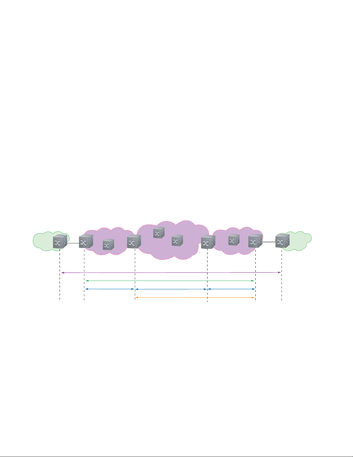
There is a need for Layer 2 equivalents to manage and troubleshoot native Layer 2 Ethernet networks. With
these tools, you can identify , isolate, and repair faults quickly and easily, which reduces operational cost of
running the network. OAM also increases availability and reduces mean time to recovery , which allows for
tighter service level agreements, resulting in increased revenue for the service provider.
In addition to providing end-to-end OAM in native Layer 2 Ethernet Service Provider/Metro networks,
you can also use CFM to manage and troubleshoot any Layer 2 network including enterprise, datacenter,
and cluster networks.
Maintenance Domains
www.dell.com | support.dell.com
Connectivity Fault Management (CFM) divides a network into hierarchical maintenance domains, as
shown in Figure 5-1.
A CFM maintenance domain is a management space on a network that is owned and operated by a single
management entity . The network administrator assigns a unique maintenance level (0 to 7) to each domain
to define the hierarchical relationship between domains. Domains can touch or nest but cannot overlap or
intersect as that would require management by multiple entities.
Figure 5-1. OAM Domains
Customer Network
Ethernet Access
Operator Domain (5)
Service Provider Network
MPLS Core MPLS Access
Customer Domain (7)
Provider Domain (6)
)
Operator Dom
M
PLS D
ain (5
omain (
4)
erator Do
Op
Customer Network
main (5)
Maintenance Points
Domains are comprised of logical entities called Maintenance Points. A maintenance point is an interface
demarcation that confines CFM frames to a domain. There are two types of maintenance points:
• Maintenance End Points (MEPs): a logical entity that marks the end-point of a domain
• Maintenance Intermediate Points (MIPs): a logical entity configured at a port of a switch that is an
intermediate point of a Maintenance Entity (ME). An ME is a point-to-point relationship between two
MEPs within a single domain. MIPs are internal to a domain, not at the boundary , and respond to CFM
only when triggered by linktrace and loopback messages. MIPs can be configured to snoop Continuity
Check Messages (CCMs) to build a MIP CCM database.
80 | 802.1ag
Page 81

These roles define the relationships between all devices so that each device can monitor the layers under its
responsibility. Maintenance points drop all lower-level frames and forward all higher-level frames.
Figure 5-2. Maintenance Points
Customer Network
Service Provider Network
Customer Network
Ethernet Access
Operator Domain (5)
MEP
Maintenance End Points
A Maintenance End Point (MEP) is a logical entity that marks the end-point of a domain. There are two
types of MEPs defined in 802.1ag for an 802.1 bridge:
• Up-MEP: monitors the forwarding path internal to an bridge on the customer or provider edge; on
Dell Networking systems the internal forwarding path is effectively the switch fabric and forwarding
engine.
• Down-MEP: monitors the forwarding path external another bridge.
Configure Up- MEPs on ingress ports, ports that send traffic towards the bridge relay. Configure
Down-MEPs on egress ports, ports that send traffic away from the bridge relay.
MPLS Core MPLS Access
Customer Domain (7)
Provider Domain (6)
ator Dom
per
O
MPLS Domain (4)
MIP
ain (5)
Operator Domain (5)
Figure 5-3. Up-MEP versus Down-MEP
Customer Network
towards relay
Up-MEP
Down-MEP
away from relay
Service Provider Ethernet Access
802.1ag | 81
Page 82

Implementation Information
• Since the S-Series has a single MAC address for all physical/LAG interfaces, only one MEP is allowed
per MA (per VLAN or per MD level).
Configure CFM
Configuring CFM is a five-step process:
1. Configure the ecfmacl CAM region using the
www.dell.com | support.dell.com
ACL Sub-partitions.
2. Enable Ethernet CFM.
3. Create a Maintenance Domain.
4. Create a Maintenance Association.
5. Create Maintenance Points.
6. Use CFM tools:
a Continuity Check Messages
b Loopback Message and Response
c Linktrace Message and Response
Related Configuration Tasks
• Enable CFM SNMP Traps
• Display Ethernet CFM Statistics
cam-acl command. See Configuring Ingress Layer 2
82 | 802.1ag
Page 83

Enable Ethernet CFM
Task Command Syntax Command Mode
Spawn the CFM process. No CFM configuration is
allowed until the CFM process is spawned.
Disable Ethernet CFM without stopping the CFM
process.
ethernet cfm
disable
CONFIGURATION
ETHERNET CFM
Create a Maintenance Domain
Connectivity Fault Management (CFM) divides a network into hierarchical maintenance domains, as
shown in Figure 5-1.
Step Task Command Syntax Command Mode
1 Create maintenance domain. domain name md-level number
Range: 0-7
2 Display maintenance domain information. show ethernet cfm domain [name |
brief]
FTOS# show ethernet cfm domain
Domain Name: customer
Level: 7
Total Service: 1
Services
MA-Name VLAN CC-Int X-CHK Status
My_MA 200 10s enabled
Domain Name: praveen
Level: 6
Total Service: 1
Services
MA-Name VLAN CC-Int X-CHK Status
Your_MA 100 10s enabled
ETHERNET CFM
EXEC Privilege
802.1ag | 83
Page 84

Create a Maintenance Association
A Maintenance Association MA is a subdivision of an MD that contains all managed entities
corresponding to a single end-to-end service, typically a VLAN. An MA is associated with a VLAN ID.
Task Command Syntax Command Mode
Create maintenance association. service name vlan vlan-id ECFM DOMAIN
Create Maintenance Points
www.dell.com | support.dell.com
Domains are comprised of logical entities called Maintenance Points. A maintenance point is a interface
demarcation that confines CFM frames to a domain. There are two types of maintenance points:
• Maintenance End Points (MEPs): a logical entity that marks the end-point of a domain
• Maintenance Intermediate Points (MIPs): a logical entity configured at a port of a switch that
constitutes intermediate points of an Maintenance Entity (ME). An ME is a point-to-point relationship
between two MEPs within a single domain.
These roles define the relationships between all devices so that each device can monitor the layers under its
responsibility.
Create a Maintenance End Point
A Maintenance End Point (MEP) is a logical entity that marks the end-point of a domain. There are two
types of MEPs defined in 802.1ag for an 802.1 bridge:
• Up-MEP: monitors the forwarding path internal to an bridge on the customer or provider edge; on
Dell Networking systems the internal forwarding path is effectively the switch fabric and forwarding
engine.
• Down-MEP: monitors the forwarding path external another bridge.
Configure Up- MEPs on ingress ports, ports that send traffic towards the bridge relay. Configure
Down-MEPs on egress ports, ports that send traffic away from the bridge relay.
Task Command Syntax Command Mode
Create an MEP. ethernet cfm mep {up-mep | down-mep} domain {name |
level
} ma-name name mepid mep-id
Range: 1-8191
Display configured MEPs and
MIPs.
show ethernet cfm maintenance-points local [mep | mip] EXEC Privilege
INTERFACE
84 | 802.1ag
Page 85

Task Command Syntax Command Mode
FTOS#show ethernet cfm maintenance-points local mep
------------------------------------------------------------------------------MPID Domain Name Level Type Port CCM-Status MA Name VLAN Dir MAC
-------------------------------------------------------------------------------
100 cfm0 7 MEP Gi 4/10 Enabled test0 10 DOWN 00:01:e8:59:23:45
200 cfm1 6 MEP Gi 4/10 Enabled test1 20 DOWN 00:01:e8:59:23:45
300 cfm2 5 MEP Gi 4/10 Enabled test2 30 DOWN 00:01:e8:59:23:45
Create a Maintenance Intermediate Point
Maintenance Intermediate Point (MIP) is a logical entity configured at a port of a switch that constitutes
intermediate points of an Maintenance Entity (ME). An ME is a point-to-point relationship between two
MEPs within a single domain. An MIP is not associated with any MA or service instance, and it belongs to
the entire MD.
Task Command Syntax Command Mode
Create an MIP. ethernet cfm mip domain {name | level} ma-name name INTERFACE
Display configured MEPs and
show ethernet cfm maintenance-points local [mep | mip] EXEC Privilege
MIPs.
FTOS#show ethernet cfm maintenance-points local mip
------------------------------------------------------------------------------MPID Domain Name Level Type Port CCM-Status MA Name VLAN Dir MAC
-------------------------------------------------------------------------------
0 service1 4 MIP Gi 0/5 Disabled My_MA 3333 DOWN 00:01:e8:0b:c6:36
0 service1 4 MIP Gi 0/5 Disabled Your_MA 3333 UP 00:01:e8:0b:c6:36
MP Databases
CFM maintains two MP databases:
• MEP Database (MEP-DB): Every MEP must maintain a database of all other MEPs in the MA that
have announced their presence via CCM.
• MIP Database (MIP-DB): Every MIP must maintain a database of all other MEPs in the MA that
have announced their presence via CCM
Task Command Syntax Command Mode
Display the MEP Database. show ethernet cfm maintenance-points remote detail [active
| domain {level | name} | expired | waiting]
EXEC Privilege
802.1ag | 85
Page 86

Task Command Syntax Command Mode
FTOS#show ethernet cfm maintenance-points remote detail
MAC Address: 00:01:e8:58:68:78
Domain Name: cfm0
MA Name: test0
Level: 7
VLAN: 10
MP ID: 900
Sender Chassis ID: FTOS
MEP Interface status: Up
MEP Port status: Forwarding
www.dell.com | support.dell.com
Receive RDI: FALSE
MP Status: Active
Display the MIP Database.
show ethernet cfm mipdb
EXEC Privilege
MP Database Persistence
Task Command Syntax Command Mode
Set the amount of time that data
from a missing MEP is kept in
the Continuity Check Database.
database hold-time minutes
Default: 100 minutes
Range: 100-65535 minutes
ECFM DOMAIN
86 | 802.1ag
Page 87

Continuity Check Messages
Continuity Check Messages (CCM) are periodic hellos used to:
• discover MEPs and MIPs within a maintenance domain
• detect loss of connectivity between MEPs
• detect misconfiguration, such as VLAN ID mismatch between MEPs
• to detect unauthorized MEPs in a maintenance domain
Continuity Check Messages (CCM) are multicast Ethernet frames sent at regular intervals from each MEP.
They have a destination address based on the MD level (01:80:C2:00:00:3X where X is the MD level of
the transmitting MEP from 0 to 7). All MEPs must listen to these multicast MAC addresses and process
these messages. MIPs may optionally processes the CCM messages originated by MEPs and construct a
MIP CCM database.
MEPs and MIPs filter CCMs from higher and lower domain levels as described in Table 5-1.
Table 5-1. Continuity Check Message Processing
Frames at Frames from UP-MEP Action Down-MEP Action MIP Action
Less than my level Bridge-relay side or Wire side Drop Drop Drop
My level Bridge-relay side Consume Drop Add to MIP-DB
Wire side Drop Consume
Greater than my level Bridge-relay side or Wire side Forward Forward Forward
and forward
All the remote MEPs in the maintenance domain are defined on each MEP. Each MEP then expects a
periodic CCM from the configured list of MEPs. A connectivity failure is then defined as:
1. Loss of 3 consecutive CCMs from any of the remote MEP, which indicates a network failure
2. Reception of a CCM with an incorrect CCM transmission interval, which indicates a configuration
error.
3. Reception of CCM with an incorrect MEP ID or MAID, which indicates a configuration or
cross-connect error. This could happen when different VLANs are cross-connected due to a
configuration error.
4. Reception of a CCM with an MD level lower than that of the receiving MEP, which indicates a
configuration or cross-connect error.
5. Reception of a CCM containing a port status/interface status TLV, which indicates a failed bridge or
aggregated port.
The Continuity Check protocol sends fault notifications (Syslogs, and SNMP traps if enabled) whenever
any of the above errors are encountered.
802.1ag | 87
Page 88

Enable CCM
Step Task Command Syntax Command Mode
1 Enable CCM.
2 Configure the transmit interval (mandatory).
The interval specified applies to all MEPs in
the domain.
Enable Cross-checking
www.dell.com | support.dell.com
Task Command Syntax Command Mode
Enable cross-checking.
Start the cross-check operation for an MEP.
Configure the amount of time the system waits for a
remote MEP to come up before the cross-check operation
is started.
Loopback Message and Response
no ccm disable
Default: Disabled
ccm transmit-interval seconds
Default: 10 seconds
mep cross-check enable
Default: Disabled
mep cross-check mep-id
mep cross-check start-delay
number
ECFM DOMAIN
ECFM DOMAIN
ETHERNET CFM
ETHERNET CFM
ETHERNET CFM
Loopback Message and Response (LBM, LBR), also called Layer 2 Ping, is an administrative echo
transmitted by MEPs to verify reachability to another MEP or MIP within the maintenance domain. LBM
and LBR are unicast frames.
Task Command Syntax Command Mode
Send a Loopback message. ping ethernet domain name ma-name ma-name remote
{mep-id | mac-addr mac-address} source {mep-id | port
interface}
EXEC Privilege
Linktrace Message and Response
Linktrace Message and Response (LTM, LTR), also called Layer 2 Traceroute, is an administratively sent
multicast frames transmitted by MEPs to track, hop-by-hop, the path to another MEP or MIP within the
maintenance domain. All MEPs and MIPs in the same domain respond to an LTM with a unicast LTR.
Intermediate MIPs forward the LTM toward the target MEP.
88 | 802.1ag
Page 89

Figure 5-4. Linktrace Message and Response
MPLS Core
MEP
MIP MIP
L
i
n
k
t
r
a
c
e
g
a
s
s
e
e
M
m
L
i
n
k
t
r
a
c
e
R
e
s
n
o
p
s
e
MIP
Link trace messages carry a unicast target address (the MAC address of an MIP or MEP) inside a multicast
frame. The destination group address is based on the MD level of the transmitting MEP
(01:80:C2:00:00:3[8 to F]). The MPs on the path to the target MAC address reply to the LTM with an LTR,
and relays the LTM towards the target MAC until the target MAC is reached or TTL equals 0.
Task Command Syntax Command Mode
Send a Linktrace message. Since the
L TM is a Multicast message sent to the
entire ME, there is no need to specify a
destination.
traceroute ethernet domain
EXEC Privilege
Link Trace Cache
After a Link Trace command is executed, the trace information can be cached so that you can view it later
without retracing.
Task Command Syntax Command Mode
Enable Link Trace caching.
Set the amount of time a trace result is cached. traceroute cache hold-time minutes
Set the size of the Link Trace Cache. traceroute cache size entries
Display the Link Trace Cache.
traceroute cache
Default: 100 minutes
Range: 10-65535 minutes
Default: 100
Range: 1 - 4095 entries
show ethernet cfm traceroute-cache
CONFIGURATION
ETHERNET CFM
ETHERNET CFM
EXEC Privilege
802.1ag | 89
Page 90

Task Command Syntax Command Mode
FTOS#show ethernet cfm traceroute-cache
Traceroute to 00:01:e8:52:4a:f8 on Domain Customer2, Level 7, MA name Test2 with VLAN 2
-----------------------------------------------------------------------------Hops Host IngressMAC Ingr Action Relay Action Next Host Egress MAC Egress Action FWD Status
------------------------------------------------------------------------------
4 00:00:00:01:e8:53:4a:f8 00:01:e8:52:4a:f8 IngOK RlyHit 00:00:00:01:e8:52:4a:f8 Terminal MEP
Delete all Link Trace Cache entries.
Enable CFM SNMP Traps
www.dell.com | support.dell.com
Task Command Syntax Command Mode
Enable SNMP trap messages for
Ethernet CFM.
A Trap is sent only when one of the five highest priority defects occur, as shown in Table 5-2.
Table 5-2. ECFM SNMP Traps
Cross-connect defect
Error-CCM defect
MAC Status defect
Remote CCM defect
RDI defect
%ECFM-5-ECFM_XCON_ALARM: Cross connect fault detected by MEP 1 in Domain customer1
at Level 7 VLAN 1000
%ECFM-5-ECFM_ERROR_ALARM: Error CCM Defect detected by MEP 1 in Domain customer1
at Level 7 VLAN 1000
%ECFM-5-ECFM_MAC_STATUS_ALARM: MAC Status Defect detected by MEP 1 in Domain
provider at Level 4 VLAN 3000
%ECFM-5-ECFM_REMOTE_ALARM: Remote CCM Defect detected by MEP 3 in Domain customer1
at Level 7 VLAN 1000
%ECFM-5-ECFM_RDI_ALARM: RDI Defect detected by MEP 3 in Domain customer1 at Level
7 VLAN 1000
clear ethernet cfm traceroute-cache
snmp-server enable traps ecfm
EXEC Privilege
CONFIGURATION
90 | 802.1ag
Page 91

Three values are given within the trap messages: MD Index, MA Index, and MPID. You can reference
these values against the output of
local mep
.
FTOS#show ethernet cfm maintenance-points local mep
------------------------------------------------------------------------------MPID Domain Name Level Type Port CCM-Status
MA Name VLAN Dir MAC
-------------------------------------------------------------------------------
100 cfm0 7 MEP Gi 4/10 Enabled
test0 10 DOWN 00:01:e8:59:23:45
FTOS(conf-if-gi-0/6)#do show ethernet cfm domain
Domain Name: My_Name
MD Index: 1
Level: 0
Total Service: 1
Services
MA-Index MA-Name VLAN CC-Int X-CHK Status
1 test 0 1s enabled
Domain Name: Your_Name
MD Index: 2
Level: 2
Total Service: 1
Services
MA-Index MA-Name VLAN CC-Int X-CHK Status
1 test 100 1s enabled
show ethernet cfm domain and show ethernet cfm maintenance-points
Display Ethernet CFM Statistics
Task Command Syntax Command Mode
Display MEP CCM statistics. show ethernet cfm statistics [domain {name | level}
vlan-id
vlan-id mpid mpid
FTOS# show ethernet cfm statistics
Domain Name: Customer
Domain Level: 7
MA Name: My_MA
MPID: 300
CCMs:
Transmitted: 1503 RcvdSeqErrors: 0
LTRs:
Unexpected Rcvd: 0
LBRs:
Received: 0 Rcvd Out Of Order: 0
Received Bad MSDU: 0
Transmitted: 0
EXEC Privilege
802.1ag | 91
Page 92

Task Command Syntax Command Mode
Display CFM statistics by port. show ethernet cfm port-statistics [interface] EXEC Privilege
FTOS#show ethernet cfm port-statistics interface gigabitethernet 0/5
Port statistics for port: Gi 0/5
==================================
RX Statistics
=============
Total CFM Pkts 75394 CCM Pkts 75394
LBM Pkts 0 LTM Pkts 0
LBR Pkts 0 LTR Pkts 0
Bad CFM Pkts 0 CFM Pkts Discarded 0
www.dell.com | support.dell.com
CFM Pkts forwarded 102417
TX Statistics
=============
Total CFM Pkts 10303 CCM Pkts 0
LBM Pkts 0 LTM Pkts 3
LBR Pkts 0 LTR Pkts 0
92 | 802.1ag
Page 93

802.3ah
802.3ah is available only on platform: s
A metropolitan area network (MAN) is a set of LANs, geographically separated but managed by a single
entity. If the distance is large—across a city, for example—connectivity between LANs is managed by a
service provider. While LANs use Ethernet, service providers networks use an array of protocols (PPP and
ATM), and a variety access technologies. Implementing Ethernet from end to end, across the service
provider network, simplifies design and management, increases scalability and bandwidth, and reduces
costs.
Ethernet in a service provider environment introduces the concept of Carrier-class Ethernet and requires
some basic management and diagnostic tools. Ethernet Operations, Administration, and Maintenance
(OAM) is that toolset, which can be used to install, monitor, troubleshoot, and manage Ethernet
infrastructure deployments. It consists of three main areas:
6
1. Service Layer OAM: IEEE 802.1ag, Connectivity Fault Management (CFM)
2. Link Layer OAM: IEEE 802.3ah, Ethernet in the First Mile (EFM) OAM
3. Ethernet Local management Interface (MEF-16 E-LMI)
Link Layer OAM Overview
Link Layer OAM introduces the toolset required to effectively monitor the link between the customer and
service provider, which is called the first mile. Currently, service providers use a variety of access
technologies including ISDN, DSL, and coax cable in the first mile. Implementing Ethernet here reduces
the types of equipment in the subscriber access network, simplifying installation and management, and
increasing bandwidth.
Link Layer OAM performs four primary operations for the purposes of link status, performance
monitoring, and fault detection and isolation for Ethernet in the First Mile:
• OAM Discovery—detects whether the remote system is OAM capable, and negotiates OAM
parameters.
• Link Event Monitoring—defines a set of events that may impact link operation, and monitors the link
for those events.
802.3ah | 93
Page 94

• Remote Loopback—directs the remote system to reflects back frames that the local system transmits
so that an administrator can isolate a fault.
• Remote Failure Indication—notifies a peer of a critical link event.
Link Layer OAMPDUs
Link Layer OAM is conducted using OAMPDUs, shown in Figure 6-1. OAM is a slow protocol and by
requirement may transmit no more than 10 frames per second, transmits to a multicast destination MAC,
and uses an Ethernet subtype.
Figure 6-1. OAMPFU Frame Format
www.dell.com | support.dell.com
00: Information
01: Event Notification
02: Variable Request
03: Variable Response
04: Loopback Control
05-FD: Reserved
FE: Organization Specific
FF: Reserved
Destination MAC
(01-80-c2-00-00-02)
Slow Protocol
multicast address
Source MAC
Length/Type
(0x8809)
Sub-type
(0x03)
Slow Protocols
use a subtype
0: Link Fault
1: Dying Gasp
2: Critical Event
3: Local Evaluating
Flags Code
Payload
(TLVs)
4: Local Stable
5: Remote Evaluating
6: Remote Stable
7-15: Reserved
Padding
FCS
There are six OAMPDU types, identified by the Code field:
• Information—carries state information and Local Information and/or Remote Information TLVs.
Information OAMPDUs are used in discovery, and as keepalives.
• Local Information TLVs—indicates support for variable retrieval, link performance events, and
remote loopback, unidirectional support, and OAM mode
• Remote Information TLVs—a copy of the peer’s Local Information TLV.
• Event Notification—carries TLVs for each concurrent link fault.
• Variable Request—carries MIB object descriptors for which the remote peer should return values.
• Variable Response—carries the requested MIB object values.
• Loopback Control—carries the loopback control command (enable and disable).
• Organization Specific—contains and OUI followed by data, the format and function of which is
defined by the organization.
OAMPDU Flags
1-bit flags are used it indicate OAM state and link state. During discovery , flags 3-6 are used to indicate the
state of peership establishment. Flags 0-2 are used to indicate a local critical link event to the remote peer.
94 | 802.3ah
Page 95

Link Layer OAM Operational Modes
When participating in EFM OAM, system may operate in active or passive mode.
• Active mode—Active mode systems initiate discovery. Once the Discovery process completes, they
can send any OAMPDU while connected to a peer in Active mode, and a subset of OAMPDUs if the
peer is in Passive mode (see Table 6-1).
• Passive mode—Passive mode systems wait for an active mode system to initiate discovery , and do not
send Variable Request or Loopback Control OAMPDUs.
Taken from IEEE 802.3ah, Table 6-1 summarizes the permitted actions in each role.
Table 6-1. Active Mode and Passive Mode Behaviors
Capability Active Passive
Initiates OAM Discovery process Yes No
Reacts to OAM Discovery process initiation Yes Yes
Required to send Information OAMPDUs Yes Yes
Permitted to send Event Notification OAMPDUs Yes Yes
Permitted to send Variable Request OAMPDUs Yes No
Permitted to send Variable Response OAMPDUs (the peer must be in Active mode) Yes Yes
Permitted to send Loopback Control OAMPDUs Yes No
Reacts to Loopback Control OAMPDUs (the peer must be in Active mode) Yes Yes
Permitted to send Organization Specific OAMPDUs Yes Yes
Link Layer OAM Discovery
OAM Discovery is the mechanism a Link Layer OAM-capable system uses to determine if the remote
system on the link has OAM functionality enabled. OAM Discovery ascertains OAM parameters, such as
maximum allowable OAMPDU size, and supported functions such as OAM remote loopback.
The discovery process is as follows:
1. If the link is not in Fault state, Active mode systems send Information OAMPDUs that contain (only)
the Local Information TLV.
2. Once a system receives an Information OAMPDU, it responds with an Information OAMPDU that
contains the Local and Remote Information TLV. Negotiation is complete when both systems have
received their peer’s information and are satisfied with it; to be satisfied, both peers on the link must be
have link performance event monitoring enabled.
3. When negotiation is complete, both peers may send any type of OAMPDU.
802.3ah | 95
Page 96

Link Layer OAM Events
Link Layer OAM defines a set of events that may impact link operation, and monitors the link for those
events. If an event occurs, the detecting system notifies its peer. There are two types of events:
• Critical Link Events—There are three critical events; each has an associated flag which can be set in
the OAMPDU when the event occurs. Critical link events are communicated to the peer using Remote
Failure Indication.
• Link Fault—A fault occurred in the receive direction of the local peer.
• Dying Gasp—An unrecoverable local failure condition occurred. Dying Gasp notification is not
supported on S-Series.
• Critical Event—An unspecified critical event occurred. Critical Event notification is not
www.dell.com | support.dell.com
• Link Performance Events—Link events are either symbol errors or frame errors, and are
supported on S-Series.
communicated using Link Event TLVs.
• Symbol Errors—a symbol is an (electrical or optical) pulse on the physical medium that
represents one or more bits. A symbol error occurs when a symbol degrades in transit so that the
receiver is not able to decode it. Gigabit and 10-Gigabit Ethernet have and expect symbol rate, also
called Baud.
• Frame Errors—frame errors are frames with a bad CRC.
Remote Loopback
An active-mode device can place a passive peer into loopback mode by sending a Loopback Control
OAMPDU. When in loopback mode:
• the remote peer returns unaltered all non-OAMPDU frames sent by the local peer, and
• all outbound data frames are discarded (control frames are still forwarded).
Implementation Information
• Critical Link Events Dying Gasp and Critical Event are not supported.
• MIB retrieval is not supported.
• Both peers on a link must have Link Performance Monitoring Enabled, or else discovery does not
complete.
• Control frames are still forwarded when an interface is in loopback mode.
96 | 802.3ah
Page 97

Configuring Link Layer OAM
Configuring Link Layer OAM is a two-step process:
1. Enable Link Layer OAM.
2. Enable any or all of the following:
a Link Performance Event Monitoring
b Remote Failure Indication
c Remote Loopback
Related Configuration Tasks
• Adjust the OAMPDU Transmission Parameters
• Display Link Layer OAM Configuration and Statistics
• Manage Link Layer OAM
Enable Link Layer OAM
Link Layer OAM is disabled by default. Enabling it places the system in Active mode and initiates OAM
discovery .Both peers on the link must be have link performance event monitoring enabled for discovery to
complete.
Task Command Syntax Command Mode
Enable Ethernet OAM.
Display the OAM discovery status. show ethernet oam discovery interface interface EXEC Privilege
ethernet oam
Default: Disabled
INTERFACE
802.3ah | 97
Page 98

Task Command Syntax Command Mode
FTOS# show ethernet oam discovery interface <interface-name>
Output format:
<interface name>
Local client
__________
Administrative configurations:
Mode:active
Unidirection:not supported
Link monitor:supported (on)
Remote loopback:not supported
MIB retrieval:not supported
Mtu size:1500
Operational status:
www.dell.com | support.dell.com
Port status:operational
Loopback status:no loopback
PDU permission:any
PDU revision:1
Remote client
___________
MAC address:0030.88fe.87de
Vendor(OUI):0x00 0x00 0x0C
Administrative configurations:
Mode:active
Unidirection:not supported
Link monitor:supported
Remote loopback:not supported
MIB retrieval:not supported
Mtu size:1500
Display Link Layer OAM sessions.
FTOS# show ethernet oam summary
Output format :
Symbols:* - Master Loopback State, # - Slave Loopback State
Capability codes:L - Link Monitor, R - Remote Loopback
U - Unidirection,V - Variable Retrieval
LocalRemote
InterfaceMAC AddressOUIModeCapability
Gi6/1/10023.84ac.b8000000DactiveL R
show ethernet oam summary
EXEC Privilege
98 | 802.3ah
Page 99

Adjust the OAMPDU Transmission Parameters
Task Command Syntax Command Mode
Specify a the maximum or minimum
number of OAMPDUs to be sent per
second.
Set the transmission mode to active or
passive.
Specify the amount of time that the
system waits to receive an OAMPDU
from a peer before considering it
non-operational.
ethernet oam [max-rate value | min-rate value]
Range: 1-10
Default: 10
ethernet oam mode {active | passive}
Default: Active
ethernet oam timeout value
Range: 2-30 seconds
Default: 5 seconds
Link Performance Event Monitoring
Link Performance Event Monitoring OAM monitors the receive side of a link for a set of pre-defined
errors and executes an action when a threshold is exceeded; it is enabled by default. Both peers on the link
must be have link performance event monitoring enabled for discovery to complete.
There is a high and low threshold for each pre-defined error; an event occurs when any threshold is
exceeded. Dell Networking OS periodically polls hardware registers for the current frame and symbol
error count. If an interface exceeds a threshold, a notification is sent to the peer and the interface is placed
in error-disabled state.
INTERFACE
INTERFACE
INTERFACE
• Enable Error Monitoring
• Execute an Action upon Exceeding the High Threshold
Enable Error Monitoring
The polling interval for Link Performance Monitoring is 100 milliseconds.
Task Command Syntax Command Mode
Start (or stop) Link Performance
Monitoring on an interface.
Enable (or disable) support for Link
Performance Monitoring on an interface.
ethernet oam link-monitor on
no ethernet oam link-monitor on
Default: Enabled
ethernet oam link-monitor supported
no ethernet oam link-monitor supported
Default: Enabled
INTERFACE
INTERFACE
802.3ah | 99
Page 100

Set Threshold Values
The available pre-defined errors fall under two categories:
• Symbol Errors—a symbol is an (electrical or optical) pulse on the physical medium that represents
one or more bits. A symbol error occurs when a symbol degrades in transit so that the receiver is not
able to decode it. Gigabit and 10-Gigabit Ethernet have and expect symbol rate, also called Baud.
• Frame Errors—frame errors are frames with a bad CRC.
The available pre-defined errors are:
• Symbol Errors per Second—the number of symbol errors during a specified period exceeds a
www.dell.com | support.dell.com
threshold.
• Frame Errors per Second—the number of frame errors during a specified period exceeds a threshold.
• Frame Errors per Frame Period—the number of frame errors within the last N frames exceeds a
threshold.
• Frame Error Seconds per Time Period—an error second is a 1-second period with at least one
frame error. The Frame Error Seconds per Time Period error occurs when the number of error seconds
within the last M seconds exceeds a threshold.
Symbol Errors per Second
Task Command Syntax Command Mode
Specify the high threshold value for
symbol errors, or disable the high
threshold.
Specify the low threshold for symbol
errors.
Specify the time period for symbol
errors per second condition.
ethernet oam link-monitor symbol-period threshold
high {symbols | none}
Range: 1-65535
Default: None
ethernet oam link-monitor symbol-period threshold
low symbols
Range: 0-65535
Default: 10
ethernet oam link-monitor symbol-period window
symbols
Range: 1-65535 (times 1,000,000 symbols)
Default: 10 (10,000,000 symbols)
INTERFACE
INTERFACE
INTERFACE
100 | 802.3ah
 Loading...