

Page 1

Dell™ PowerEdge™ C1100
Systems
Hardware Owner’s
Manual
Regulatory Model CS24-TY
Page 2

Notes, Cautions, and Warnings
NOTE: A NOTE indicates important information that helps you make better use of
your computer.
CAUTION: A CAUTION indicates potential damage to hardware or loss of data if
instructions are not followed.
WARNING: A WARNING indicates a potential for property damage, personal
injury, or death.
____________________
Information in this document is subject to change without notice.
© 2009 Dell Inc. All rights reserved.
Reproduction of these materials in any manner whatsoever without the written permission of Dell Inc.
is strictly forbidden.
Trademarks used in this text: Dell, the DELL logo, and Pow er Edge are trademarks of Dell Inc.;
Intel and SpeedStep are registered trademarks of Intel Corporation in the U.S. and other countries;
Other trademarks and trade names may be used in this document to refer to either the entities claiming
the marks and names or their products. Dell Inc. disclaims any proprietary interest in trademarks and
trade names other than its own.
Regulatory Model CS24-TY
December 2009 Rev. A00
Page 3

Contents
1 About Your System . . . . . . . . . . . . . . . . . . 11
Accessing System Features During Startup. . . . . . . 11
Front-Panel Features and Indicators
. . . . . . . . . . 12
Hard-Drive Indicator Patterns . . . . . . . . . . . . . . 16
Back-Panel Features and Indicators
NIC Indicator Codes
. . . . . . . . . . . . . . . . . . . 18
Power and System Board Indicator Codes
POST Error Codes
Beep Codes
Post Beep Codes
. . . . . . . . . . . . . . . . . . . . 21
. . . . . . . . . . . . . . . . . . . . . . . 31
. . . . . . . . . . . . . . . . . . . . . 32
Other Information You May Need
. . . . . . . . . . 17
. . . . . . . 19
. . . . . . . . . . . . 32
2 Using the System Setup Program . . . . . . 33
Start Menu . . . . . . . . . . . . . . . . . . . . . . . . 33
System Setup Options at Boot
Console Redirection
. . . . . . . . . . . . . . . . . . . 34
. . . . . . . . . . . . . . 34
Main Menu
Main Screen
AMIBIOS Settings
. . . . . . . . . . . . . . . . . . . . . . . . 35
. . . . . . . . . . . . . . . . . . . . 35
. . . . . . . . . . . . . . . . . 35
Contents 3
Page 4

Processor Settings . . . . . . . . . . . . . . . . . 36
System Memory Settings
. . . . . . . . . . . . . . 36
Advanced Menu
Processor Configuration
Memory Configuration
IDE Configuration
Super IO Configuration
USB Configuration
PCI Configuration
Boot Menu
Boot Settings Configuration
Server Menu
BMC LAN Configuration
Remote Access Configuration
Security Menu
Exit Menu
. . . . . . . . . . . . . . . . . . . . . 36
. . . . . . . . . . . . . . 36
. . . . . . . . . . . . . . . 38
. . . . . . . . . . . . . . . . . . 38
. . . . . . . . . . . . . . . 39
. . . . . . . . . . . . . . . . . 39
. . . . . . . . . . . . . . . . . . 39
. . . . . . . . . . . . . . . . . . . . . . . . 41
. . . . . . . . . . . . 41
. . . . . . . . . . . . . . . . . . . . . . . 42
. . . . . . . . . . . . . . 43
. . . . . . . . . . . 44
. . . . . . . . . . . . . . . . . . . . . . 45
. . . . . . . . . . . . . . . . . . . . . . . . . 45
3 Installing System Components . . . . . . . 47
Safety Instructions . . . . . . . . . . . . . . . . . . . . 47
4 Contents
Recommended Tools
Inside the System
Hard Drives
. . . . . . . . . . . . . . . . . . . . . . . . 49
. . . . . . . . . . . . . . . . . . . 47
. . . . . . . . . . . . . . . . . . . . . 48
Removing a Hard-Drive Blank
Installing a Hard-Drive Blank
. . . . . . . . . . . . 50
Removing a Hard Drive From a Hard-Drive
. . . . . . . . . . . . . . . . . . . . . . . . 50
Carrier
. . . . . . . . . . . 49
Page 5

Installing a Hard Drive Into a Hard-Drive
. . . . . . . . . . . . . . . . . . . . . . . 51
Carrier
Removing a Hard-Drive Carrier
Installing a Hard-Drive Carrier
. . . . . . . . . . . 52
. . . . . . . . . . . 52
Opening and Closing the System
Opening the System
Closing the System
Cooling Shroud
. . . . . . . . . . . . . . . . . . . . . . 54
. . . . . . . . . . . . . . . . 53
. . . . . . . . . . . . . . . . . 54
Removing the Cooling Shroud
Installing the Cooling Shroud
Heat Sinks
Processor
. . . . . . . . . . . . . . . . . . . . . . . . 56
Removing the Heat Sink
Installing the Heat Sink
. . . . . . . . . . . . . . . . . . . . . . . . 58
. . . . . . . . . . . . . . 56
. . . . . . . . . . . . . . . 57
Removing the Processor
Installing the Processor
System Memory
. . . . . . . . . . . . . . . . . . . . . 61
. . . . . . . . . . . . . . 59
General Memory Module Installation
Guidelines
. . . . . . . . . . . . . . . . . . . . . . 61
Mode-Specific Guidelines
Supported Memory Configuration
Removing Memory Modules
Installing Memory Modules
. . . . . . . . . . . . 53
. . . . . . . . . . . 54
. . . . . . . . . . . . 55
. . . . . . . . . . . . . . 58
. . . . . . . . . . . . . 62
. . . . . . . . . 63
. . . . . . . . . . . . 64
. . . . . . . . . . . . 65
Expansion-Card Riser and Expansion Card
Removing the Expansion-Card Riser
Installing the Expansion-Card Riser
Removing the Expansion Card
Installing the Expansion Card
RAID Battery (Optional)
. . . . . . . . . . . . . . . . . 70
. . . . . . . . . . . 68
. . . . . . . . . . . 69
. . . . . . . 66
. . . . . . . . 66
. . . . . . . . 67
Contents 5
Page 6

Removing a RAID Battery . . . . . . . . . . . . . . 70
Installing a RAID Battery
. . . . . . . . . . . . . . 70
Integrated Storage Controller Cards
. . . . . . . . . . . 72
Removing the Integrated Storage Controller
Card
. . . . . . . . . . . . . . . . . . . . . . . . . 72
Installing the Integrated Storage Controller
. . . . . . . . . . . . . . . . . . . . . . . . . 73
Card
Mezzanine Card (10 GbE LAN)
. . . . . . . . . . . . . . 74
Removing the Mezzanine Card (10 GbE LAN)
Installing the Mezzanine Card (10 GbE LAN)
Power Supplies
. . . . . . . . . . . . . . . . . . . . . 77
Removing the Non-Redundant Power Supply
Installing the Non-Redundant Power Supply
Removing the Redundant Power Supply
Installing the Redundant Power Supply
Power Distribution Board
. . . . . . . . . . . . . . . . 80
Removing the Power Distribution Board
Installing the Power Distribution Board
Cooling Fans
. . . . . . . . . . . . . . . . . . . . . . . 82
Removing a Cooling Fan Assembly
Installing the Cooling Fan Assembly
. . . . 74
. . . . 76
. . . 77
. . . . 78
. . . . . . 79
. . . . . . 80
. . . . . . 80
. . . . . . 81
. . . . . . . . . 82
. . . . . . . . 83
6 Contents
Expander Board
. . . . . . . . . . . . . . . . . . . . . 84
Removing the Expander Board
Installing the Expander Board
Backplane
. . . . . . . . . . . . . . . . . . . . . . . . 86
Removing the Backplane
Installing the Backplane
. . . . . . . . . . . 84
. . . . . . . . . . . 86
. . . . . . . . . . . . . . 86
. . . . . . . . . . . . . . 88
Page 7

Control Panel (Optional) . . . . . . . . . . . . . . . . . 88
Removing the Control Panel
Installing the Control Panel
. . . . . . . . . . . . 88
. . . . . . . . . . . . . 89
Control Panel Assembly (Optional)
Removing the Control Panel Assembly
Installing the Control Panel Assembly
System Battery
. . . . . . . . . . . . . . . . . . . . . . 91
Removing the System Battery
Installing the System Battery
System Board
. . . . . . . . . . . . . . . . . . . . . . 93
Removing the System Board
Installing the System Board
. . . . . . . . . . . 89
. . . . . . . 89
. . . . . . . 90
. . . . . . . . . . . 91
. . . . . . . . . . . . 92
. . . . . . . . . . . . 93
. . . . . . . . . . . . 94
4 Troubleshooting Your System . . . . . . . . . 95
Safety First—For You and Your System . . . . . . . . . 95
Installation Problems
Troubleshooting System Startup Failure
Troubleshooting External Connections . . . . . . . . . 96
Troubleshooting the Video Subsystem
. . . . . . . . . . . . . . . . . . 95
. . . . . . . . 96
. . . . . . . . . 96
Troubleshooting a USB Device
. . . . . . . . . . . . . 96
Troubleshooting a Serial I/O Device
Troubleshooting a NIC
Troubleshooting a Wet System
. . . . . . . . . . . . . . . . . . 98
. . . . . . . . . . . . . 99
Troubleshooting a Damaged System
. . . . . . . . . . 97
. . . . . . . . . . 100
Contents 7
Page 8

Troubleshooting the System Battery. . . . . . . . . . 100
Troubleshooting Power Supplies
Troubleshooting System Cooling Problems
Troubleshooting a Fan
. . . . . . . . . . . . . . . . . 102
Troubleshooting System Memory
Troubleshooting a Hard Drive
Troubleshooting a Storage Controller
. . . . . . . . . . . 101
. . . . . . 102
. . . . . . . . . . . 103
. . . . . . . . . . . . . 105
. . . . . . . . . 106
Troubleshooting Expansion Cards . . . . . . . . . . . 107
Troubleshooting Processors
IRQ Assignment Conflicts
Troubleshooting Changes in BIOS Settings
Collecting System Event Log for Investigation
. . . . . . . . . . . . . . 108
. . . . . . . . . . . . . . . 109
. . . . . . 110
. . . . 110
5 Jumpers and Connectors. . . . . . . . . . . . 111
System Board Connectors . . . . . . . . . . . . . . . 111
8 Contents
Jumper Settings
. . . . . . . . . . . . . . . . . . . . 112
System Configuration Jumper Settings
Backplane Jumper Settings
Backplane Connectors
3.5-Inch Hard Drives
2.5-Inch Hard Drives
Power Distribution Board
. . . . . . . . . . . . . . 114
. . . . . . . . . . . . . . . . . 115
. . . . . . . . . . . . . . . 115
. . . . . . . . . . . . . . . 116
. . . . . . . . . . . . . . . 118
. . . . . . 112
Page 9

6 Getting Help. . . . . . . . . . . . . . . . . . . . . . 119
Contacting Dell . . . . . . . . . . . . . . . . . . . . . 119
Glossary . . . . . . . . . . . . . . . . . . . . . . . . . . . . 121
Index
. . . . . . . . . . . . . . . . . . . . . . . . . . . . . . 131
Contents 9
Page 10

10 Contents
Page 11

About Your System
Accessing System Features During Startup
The following keystrokes provide access to system features during startup.
Keystroke Description
<F2> Enters the System Setup program. See "Start Menu" on page 33.
<F11> Enters the BIOS Boot Manager. See "System Setup Options at Boot"
on page 34.
<F12> Starts Preboot eXecution Environment (PXE) boot.
<Ctrl><C> Enters the SAS Configuration Utility. For more information,
see the SAS adapter documentation.
<Ctrl><R> Enters the RAID configuration utility. For more information,
see the documentation for your SAS RAID card.
<Ctrl><S> Enters the utility to configure NIC settings for PXE boot. For more
information, see the documentation for your integrated NIC.
About Your System 11
Page 12
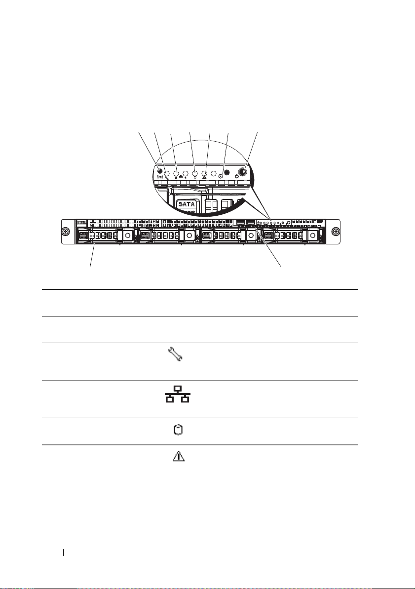
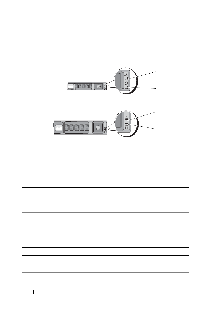
Front-Panel Features and Indicators
9
8
1
2
3
4
5
6
7
Figure 1-1. Front-Panel Features—3.5-Inch Hard-Drive System
Item Indicator, Button,
or Connector
1 Reset button Restarts the system while the system is
2 Service LED Lights when the BMC port is on and
3 Ethernet connectors 1
and 2
4 Hard drive activity
LED
5 Fault LED Displays status/errors and is controlled
Icon Description
powered on.
blinks when there is traffic on the
BMC port.
Lights green when a connection is made
to the NIC port, blinks when there is
traffic on the NIC port.
Lights when the hard drives are active.
by BMC.
12 About Your System
Page 13
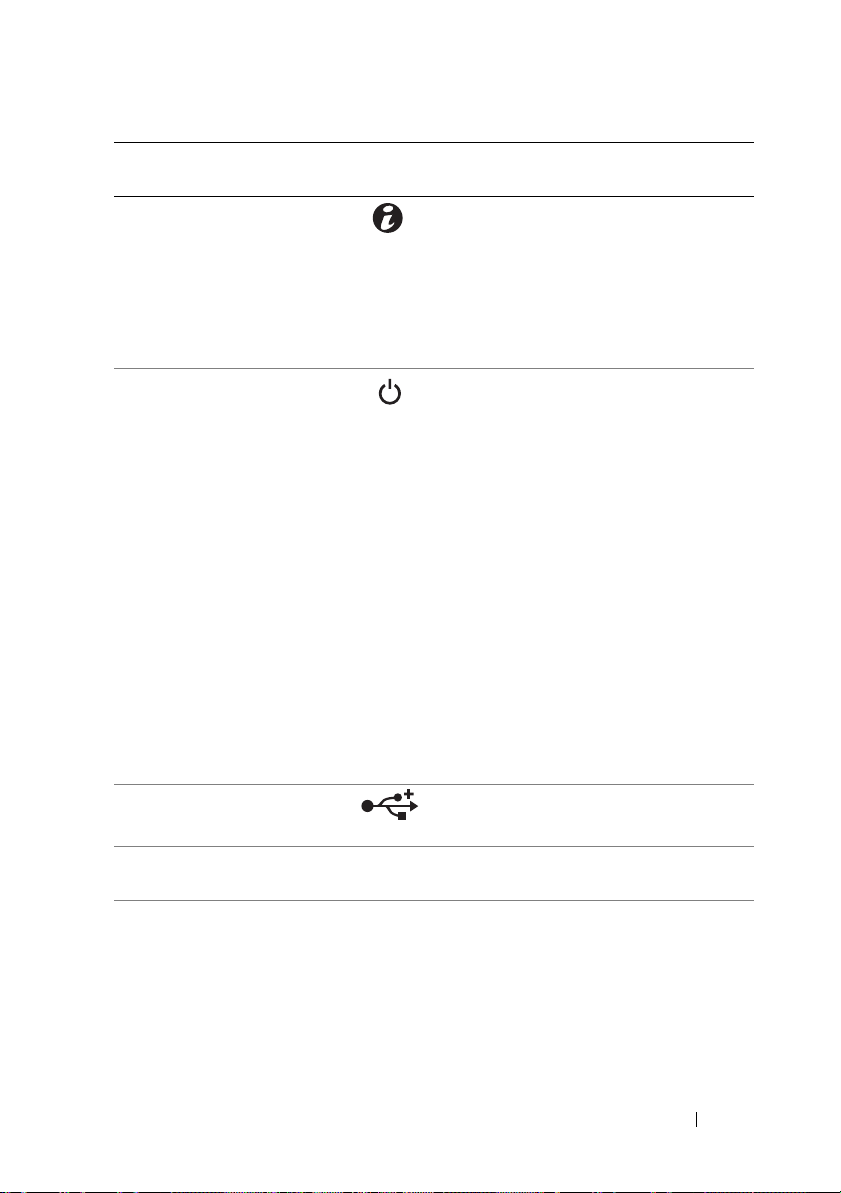
Item Indicator, Button,
or Connector
6 System identification
indicator/button
7 Power-on
indicator/power
button
Icon Description
The system identification button can
be used to locate a particular system
and system board within a rack.
When the button is pushed, the blue
system status indicators on the front
and the back blink until the button
is pushed again.
The power-on indicator lights
when the system power is on.
The power button controls the
DC power supply output to the system.
NOTE: When powering on the system,
the video monitor can take from several
seconds to over 2 minutes to display an
image, depending on the amount of
memory installed in the system.
NOTE: On ACPI-compliant operating
systems, turning off the system using the
power button causes the system to
perform a graceful shutdown before
power to the system is turned off.
NOTE: To force an ungraceful shutdown,
press and hold the power button for
5 seconds.
8 USB connectors (2) Connects USB devices to the system.
The ports are USB 2.0-compliant.
9 Hard drives Up to four hot-swappable 3.5-inch hard
drives.
About Your System 13
Page 14
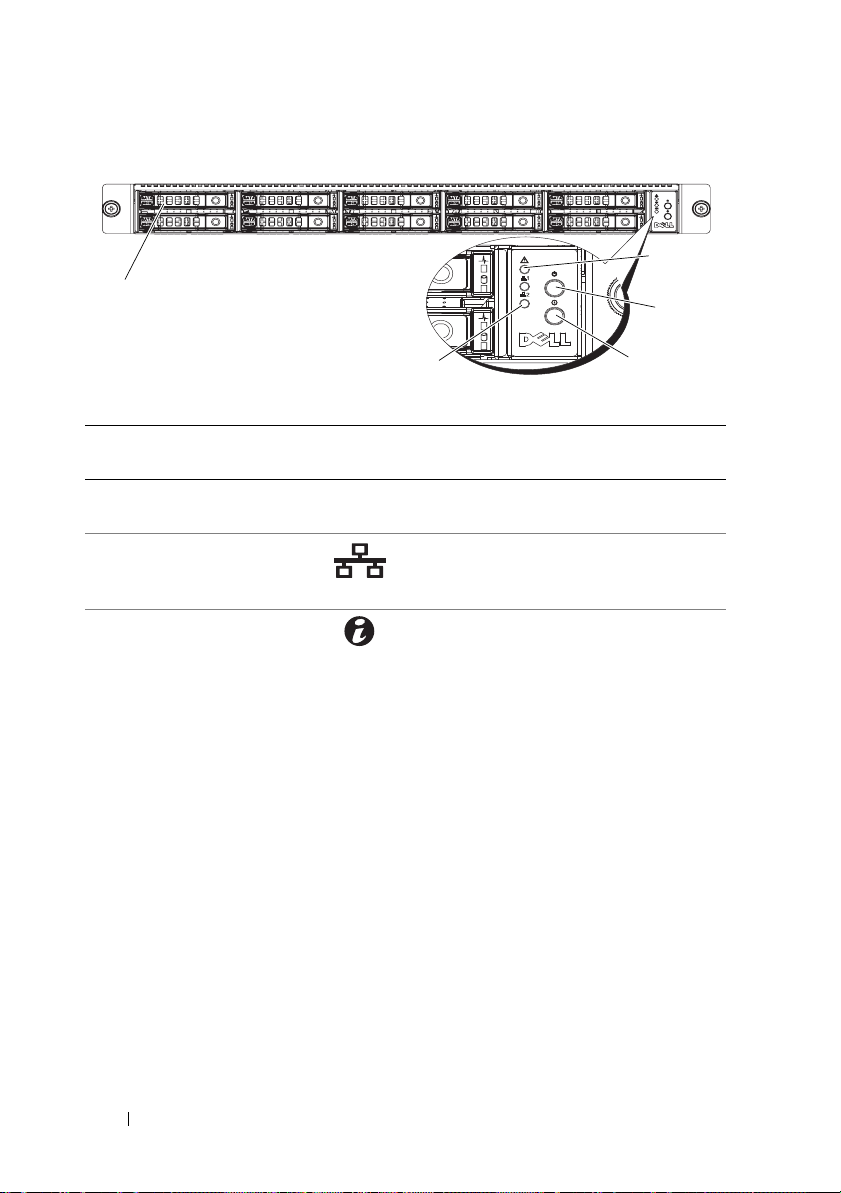
Figure 1-2. Front-Panel Features—2.5-Inch Hard-Drive Systems
1
5
4
3
2
Item Indicator, Button,
or Connector
1 Hard drives Up to ten hot-swappable 2.5-inch hard
2 Ethernet connectors 1
and 2
3 System identification
indicator/button
Icon Description
drives.
Lights green when a connection is
made to the NIC port, blinks when
there is traffic on the NIC port.
The system identification button can be
used to locate a particular system and
system board within a rack.
When the button is pushed, the blue
system status indicators on the front
and the back blink until the button
is pushed again.
14 About Your System
Page 15
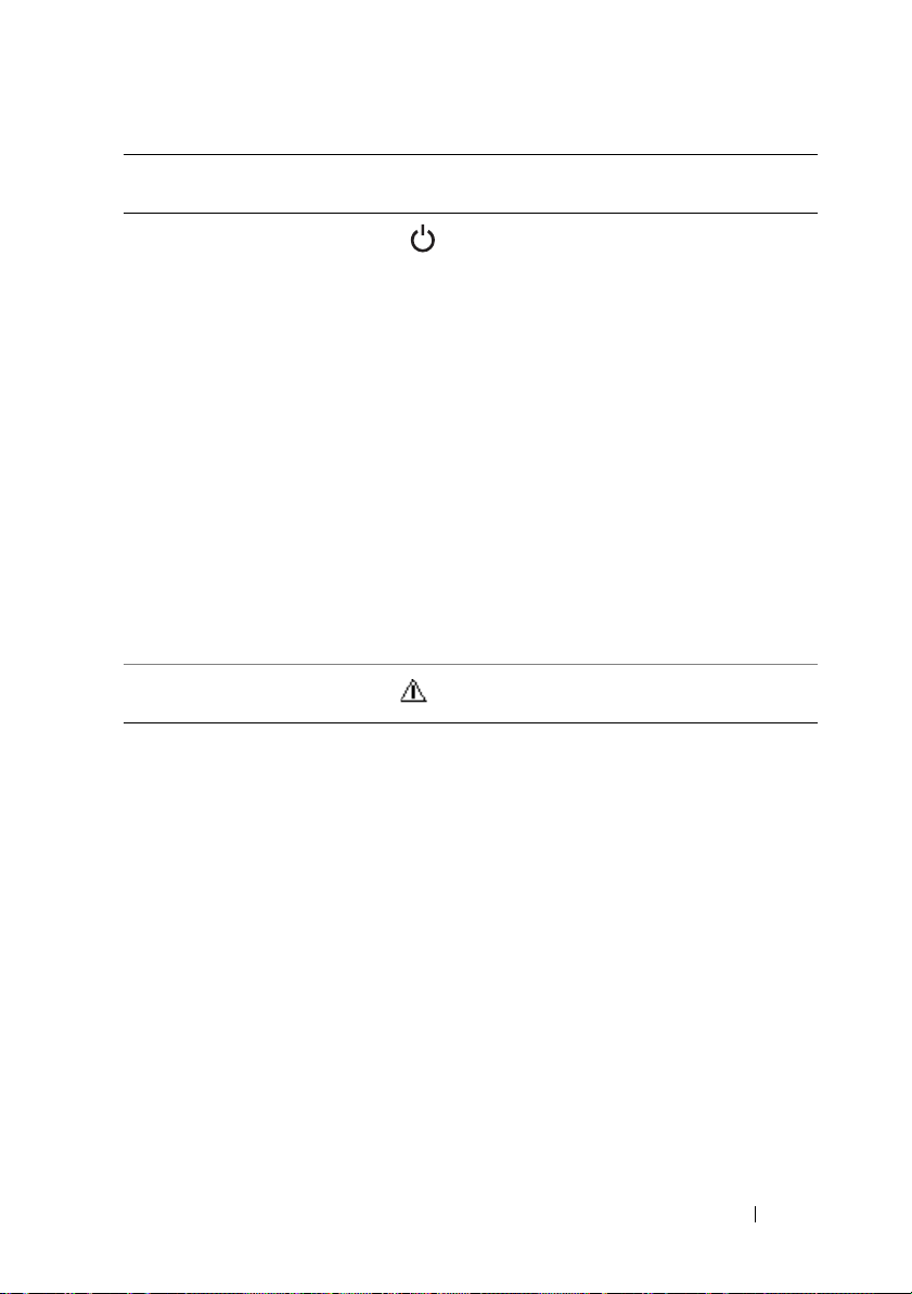
Item Indicator, Button,
or Connector
4 Power-on
indicator/power
button
Icon Description
The power-on indicator lights
when the system power is on.
The power button controls the
DC power supply output to the system.
NOTE: When powering on the system,
the video monitor can take from several
seconds to over 2 minutes to display an
image, depending on the amount of
memory installed in the system.
NOTE: On ACPI-compliant operating
systems, turning off the system using the
power button causes the system to
perform a graceful shutdown before
power to the system is turned off.
NOTE: To force an ungraceful shutdown,
press and hold the power button for
5 seconds.
5 Fault LED Displays status/errors and is controlled
by BMC.
About Your System 15
Page 16
Hard-Drive Indicator Patterns
1
2
1
2
2.5-inch hard-drive carrier
3.5-inch hard-drive carrier
Figure 1-3. Hard-Drive Indicators
1 hard-drive activity indicator
(green)
Table 1-1. Hard Drive Indicators—On-Board SATA Ports
Drive-Activity Indicator/Drive-Status Indicator Condition
Off/Off No drive
Steady green/Off No access
Steady green/Steady green Drive online
Steady green/Blinks green Drive is present or in idle stage
Table 1-2. Hard Drive Indicators—SAS/SATA Add-on Cards
Drive-Activity Indicator/Drive-Status Indicator Condition
Off/Off No drive
Steady green/Off No access
Steady green/Steady green Drive online
16 About Your System
2 hard-drive status indicator
(green and amber)
Page 17
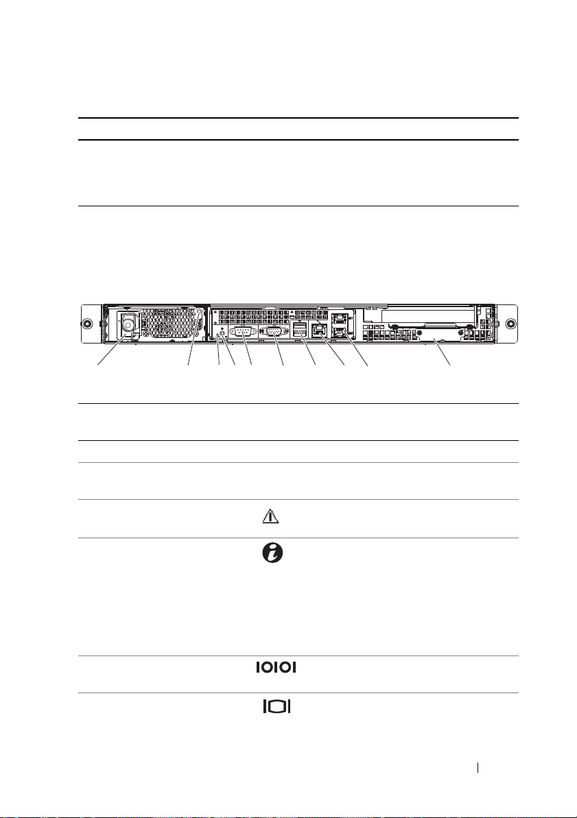
Table 1-2. Hard Drive Indicators—SAS/SATA Add-on Cards (continued)
1
45
6
7
8
9
3
2
10
Drive-Activity Indicator/Drive-Status Indicator Condition
Steady green/Blinks green Drive is present or in idle stage
Steady amber/Off Drive failed
Steady amber/Steady green Drive rebuilding
Back-Panel Features and Indicators
Figure 1-4. Back-Panel Features
Item Indicator, Button, or
Connector
1 Power supply 650 W
2 Power LED Lights green when the power supply is
3 Fault LED Displays status/errors and is controlled
4 System identification
indicator
5 Serial connector Connects a serial device to the system.
6 Video connector Connects a VGA display to the system.
Icon Description
functioning properly.
by BMC.
Both the systems management software
and the identification buttons located
on the front can cause the indicator to
flash blue to identify a particular
system and system board.
Lights amber when the system needs
attention due to a problem.
About Your System 17
Page 18
Item Indicator, Button, or
1
2
Connector
7 USB connectors (2) Connects USB devices to the system.
8 KVM over IP Port Dedicated management port.
9 Ethernet connectors (2) Embedded 10/100/1000 NIC connector.
10 Mezzanine-card cover Remove this cover before installing
Icon Description
The ports are USB 2.0-compliant.
mezzanine card.
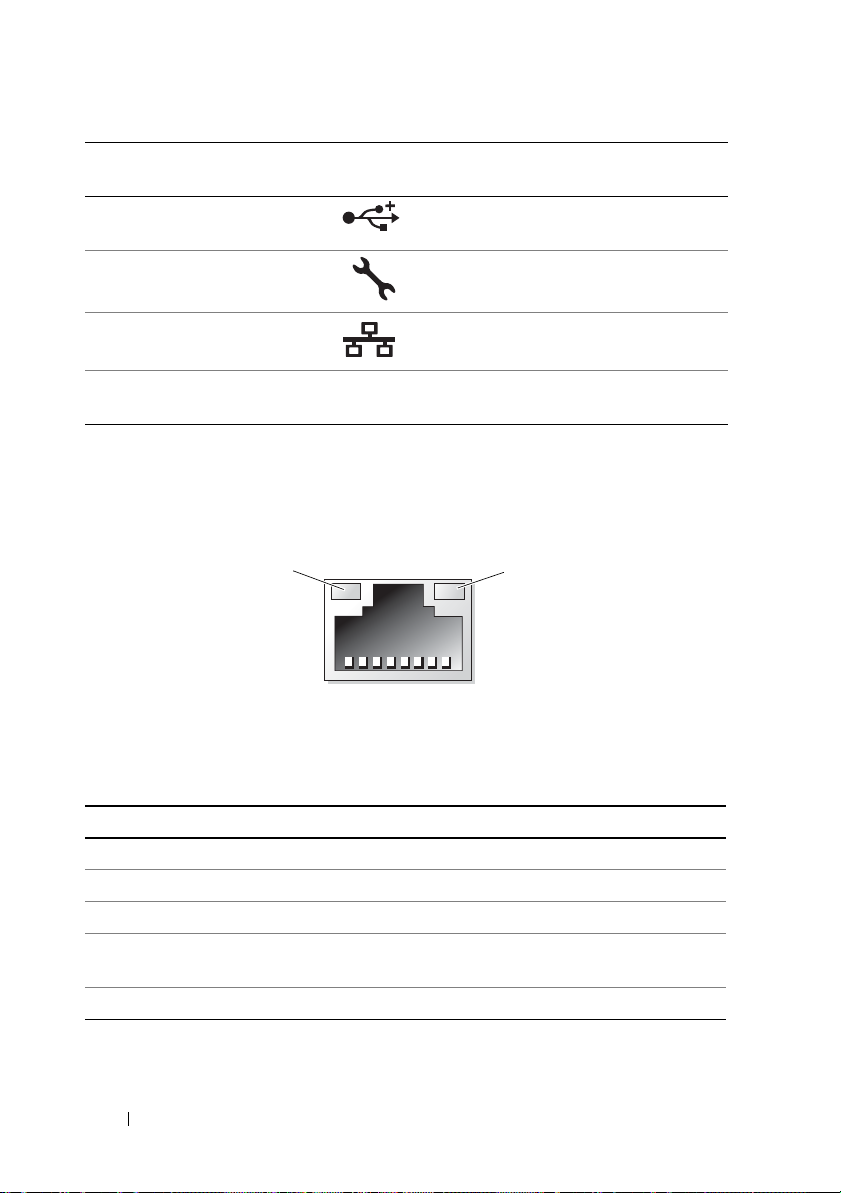
NIC Indicator Codes
Figure 1-5. NIC Indicators
1 link indicator 2 activity indicator
Table 1-3. NIC Speed Indicator Codes
NIC Speed Indicator Condition
Steady amber Link at 1 Gbps
Blinks amber Identify port with 1 Gbps connection
Steady green Link at 100 Mbps
Blinks green Identify port with 10 Mbps or 100 Mbps
connection
Green off Link at 10 Mbps
18 About Your System
Page 19

Table 1-4. NIC Indicator Codes—BMC
NIC Indicator Condition
Steady green Link LAN/No access
Blinks green Accessing LAN
Green off Idle
Table 1-5. NIC Speed Indicator Codes (KVM Over IP Port)
NIC Speed Indicator Condition
Steady green Link at 100 Mbps
Green off Link at 10 Mbps
Power and System Board Indicator Codes
The LEDs on the system front and back panel display error codes during
system startup. Systems with 2.5-inch or 3.5-inch hard drives share the
same LEDs on the front and back panel. Table 1-6 lists the status associated
with the error codes.
Table 1-6. Power and System Board Indicator Codes
Power-On Indicator Condition
Steady green, Amber off Power On (S0/S1)
Green off, Blinks amber BMC critical condition event in power
off mode (S4/S5)
Green, Blinks amber BMC critical condition event in power
off mode (S0/S1)
About Your System 19
Page 20

Table 1-7. System Identification Indicators
System Identification Indicator Condition
Steady blue IPMI using chassis identify command on or
ID button press identification on.
Blinks blue blinking Only IPMI using chassis identify command
blink on.
Blue off IPMI using chassis identify command off or
ID button press identification off.
Table 1-8. Power Indicator Codes
Power Indicator Condition
Steady green Power supply is on (AC OK/DC OK) or in
standby mode (90–264 VAC)
Steady yellow Power supply faulty
(UVP/OVP/OCP/SCP/OTP/Fan Fault)
Yellow off Power supply is off or AC input
voltage is out of normal operating range
(90 VAC–264 VAC)
Table 1-9. Fault Indicator Codes
Fault Indicator Condition
Amber blinking System failure
or
Non-critical failure: non-critical fan,
voltage, temperature state, or CPU thermal
trip.
Amber off No system failure
or
Off
20 About Your System
Page 21

POST Error Codes
Code Log in BMC Error Message Corrective Action
0000 Yes Timer Error Remove AC power to the system for
10 seconds and restart the system.
If the problem persists, see "Getting
Help" on page 119.
0003 Yes CMOS Battery Low See "Troubleshooting the System Battery"
on page 100.
0004 Yes CMOS Settings
Wro ng
0005 Yes CMOS Checksum
Bad
000B Yes CMOS memory size
Wro ng
000C Yes RAM R/W test failed Remove AC power to the system for
000E Yes A: Driver Error See "Troubleshooting a Hard Drive" on
000F Yes B: Driver Error See "Troubleshooting a Hard Drive" on
0012 Yes CMOS Date/Time
Not Set
Remove AC power to the system for
10 seconds and restart the system.
If the problem persists, see "Getting
Help" on page 119.
Remove AC power to the system for
10 seconds and restart the system.
If the problem persists, see "Getting
Help" on page 119.
Remove AC power to the system for
10 seconds and restart the system.
If the problem persists, see "Getting
Help" on page 119.
10 seconds and restart the system.
If the problem persists, see "Getting
Help" on page 119.
page 105.
page 105.
Remove AC power to the system for
10 seconds and restart the system. See
"Troubleshooting the System Battery" on
page 100.
If the problem persists, see "Getting
Help" on page 119.
About Your System 21
Page 22

Code Log in BMC Error Message Corrective Action
0040 Yes Refresh timer test
failed
0041 Yes Display memory test
failed
0042 Yes CMOS Display Type
Wro ng
0044 Yes DMA Controller
Error
0045 Yes DMA-1 Error See "Troubleshooting System Memory"
0046 Yes DMA-2 Error See "Troubleshooting System Memory"
0047 Yes Unknown BIOS
error.
0048 Yes Password check
failed
Remove AC power to the system for
10 seconds and restart the system.
If the problem persists, see "Getting
Help" on page 119.
Remove AC power to the system for
10 seconds and restart the system.
If the problem persists, see "Getting
Help" on page 119.
Remove AC power to the system for
10 seconds and restart the system.
If the problem persists, see "Getting
Help" on page 119.
See "Troubleshooting System Memory"
on page 103.
If the problem persists, see "Getting
Help" on page 119.
on page 103.
If the problem persists, see "Getting
Help" on page 119.
on page 103.
If the problem persists, see "Getting
Help" on page 119.
Remove AC power to the system for
10 seconds and restart the system.
If the problem persists, see "Getting
Help" on page 119.
Reset password. See "Jumper Settings" on
page 112.
If the problem persists, see "Getting
Help" on page 119.
22 About Your System
Page 23

Code Log in BMC Error Message Corrective Action
0049 Yes Unknown BIOS
error.
004A Yes Unknown BIOS
error.
004B Yes Unknown BIOS
error.
005E Yes Password check
failed
005D Yes S.M.A.R.T.
Command Failed
S.M.A.R.T. Status
BAD, Backup and
Replace
0060 Yes Primary Master Hard
Disk Error
0061 Yes Primary Salve Hard
Disk Error
0062 Yes Secondary Master
Hard Disk Error
0063 Yes Secondary Salve
Hard Disk Error
0080 Yes Primary Master
Drive - ATAPI
Incompatible
0081 Yes Primary Salve Drive -
ATAPI Incompatible
Remove AC power to the system for
10 seconds and restart the system.
If the problem persists, see "Getting
Help" on page 119.
Remove AC power to the system for
10 seconds and restart the system.
If the problem persists, see "Getting
Help" on page 119.
Remove AC power to the system for
10 seconds and restart the system.
If the problem persists, see "Getting
Help" on page 119.
Reset password. See "Jumper Settings" on
page 112.
If the problem persists, see "Getting
Help" on page 119.
See "Getting Help" on page 119.
See "Troubleshooting a Hard Drive" on
page 105.
See "Troubleshooting a Hard Drive" on
page 105.
See "Troubleshooting a Hard Drive" on
page 105.
See "Troubleshooting a Hard Drive" on
page 105.
See "Troubleshooting a Hard Drive" on
page 105.
See "Troubleshooting a Hard Drive" on
page 105.
About Your System 23
Page 24

Code Log in BMC Error Message Corrective Action
0082 Yes Secondary Master
Drive - ATAPI
Incompatible
0083 Yes Secondary Slave
Drive - ATAPI
Incompatible
0101 Yes Warning! This
system board does
not support the
power requirements
of the installed
processor. The
processor will be run
at a reduced
frequency, which will
impact system
performance.
0102 Yes Error! The CPU
Core to Bus ratio or
VID configuration
has failed! Please
enter BIOS Setup
and re-config it.
0120 Yes Thermal Failure
detected by
PROCHOT#.
0121 Yes Thermal Failure
detected by
PROCHOT#.
See "Troubleshooting a Hard Drive" on
page 105.
See "Troubleshooting a Hard Drive" on
page 105.
Ensure that your processors match and
conform to the type described in the
processor technical specifications
outlined in your system’s Getting Started
Guide.
See "Troubleshooting Processors" on
page 108.
The message is displayed on the screen,
an error is logged to the SEL, and user
input is required to continue. The user
can take immediate corrective action or
choose to continue booting.
Ensure that the processor heat sinks are
properly installed.
See "Troubleshooting Processors" on
page 108 and "Troubleshooting System
Cooling Problems" on page 102.
Ensure that the processor heat sinks are
properly installed.
See "Troubleshooting Processors" on
page 108 and "Troubleshooting System
Cooling Problems" on page 102.
24 About Your System
Page 25

Code Log in BMC Error Message Corrective Action
0122 Yes Thermal Failure
detected by
PROCHOT#.
0123 Yes Thermal Failure
detected by
PROCHOT#.
0124 Yes Thermal Failure
detected by
PROCHOT#.
0125 Yes Thermal Failure
detected by
PROCHOT#.
0126 Yes Thermal Failure
detected by
PROCHOT#.
0127 Yes Thermal Failure
detected by
PROCHOT#.
0150 Yes Processor failed
BIST
Ensure that the processor heat sinks are
properly installed.
See "Troubleshooting Processors" on
page 108 and "Troubleshooting System
Cooling Problems" on page 102.
Ensure that the processor heat sinks are
properly installed.
See "Troubleshooting Processors" on
page 108 and "Troubleshooting System
Cooling Problems" on page 102.
Ensure that the processor heat sinks are
properly installed.
See "Troubleshooting Processors" on
page 108 and "Troubleshooting System
Cooling Problems" on page 102.
Ensure that the processor heat sinks are
properly installed.
See "Troubleshooting Processors" on
page 108 and "Troubleshooting System
Cooling Problems" on page 102.
Ensure that the processor heat sinks are
properly installed.
See "Troubleshooting Processors" on
page 108 and "Troubleshooting System
Cooling Problems" on page 102.
Ensure that the processor heat sinks are
properly installed.
See "Troubleshooting Processors" on
page 108 and "Troubleshooting System
Cooling Problems" on page 102.
Remove AC power to the system for 10
seconds and restart the system.
If the problem persists, see "Getting
Help" on page 119.
About Your System 25
Page 26

Code Log in BMC Error Message Corrective Action
0151 Yes Processor failed
BIST
0152 Yes Processor failed
BIST
0153 Yes Processor failed
BIST
0154 Yes Processor failed
BIST
0155 Yes Processor failed
BIST
0156 Yes Processor failed
BIST
0157 Yes Processor failed
BIST
0160 Yes Processor missing
microcode
Remove AC power to the system for
10 seconds and restart the system.
If the problem persists, see "Getting
Help" on page 119.
Remove AC power to the system for
10 seconds and restart the system.
If the problem persists, see "Getting
Help" on page 119.
Remove AC power to the system for
10 seconds and restart the system.
If the problem persists, see "Getting
Help" on page 119.
Remove AC power to the system for
10 seconds and restart the system.
If the problem persists, see "Getting
Help" on page 119.
Remove AC power to the system for
10 seconds and restart the system.
If the problem persists, see "Getting
Help" on page 119.
Remove AC power to the system for
10 seconds and restart the system.
If the problem persists, see "Getting
Help" on page 119.
Remove AC power to the system for
10 seconds and restart the system.
If the problem persists, see "Getting
Help" on page 119.
A BIOS update is required.
If the problem persists, see "Getting
Help" on page 119.
26 About Your System
Page 27

Code Log in BMC Error Message Corrective Action
0161 Yes Processor missing
microcode
0162 Yes Processor missing
microcode
0163 Yes Processor missing
microcode
0164 Yes Processor missing
microcode
0165 Yes Processor missing
microcode
0166 Yes Processor missing
microcode
0167 Yes Processor missing
microcode
0180 Yes BIOS does not
support current
stepping
0181 Yes BIOS does not
support current
stepping
A BIOS update is required.
If the problem persists, see "Getting
Help" on page 119.
A BIOS update is required.
If the problem persists, see "Getting
Help" on page 119.
A BIOS update is required.
If the problem persists, see "Getting
Help" on page 119.
A BIOS update is required.
If the problem persists, see "Getting
Help" on page 119.
A BIOS update is required.
If the problem persists, see "Getting
Help" on page 119.
A BIOS update is required.
If the problem persists, see "Getting
Help" on page 119.
A BIOS update is required.
If the problem persists, see "Getting
Help" on page 119.
Ensure that your processors match
and conform to the type described in
the processor technical
specifications outlined in your
system’s Getting Started Guide.
Ensure that your processors match
and conform to the type described in
the processor technical
specifications outlined in your
system’s Getting Started Guide.
About Your System 27
Page 28

Code Log in BMC Error Message Corrective Action
0182 Yes BIOS does not
support current
stepping
0183 Yes BIOS does not
support current
stepping
0184 Yes BIOS does not
support current
stepping
0185 Yes BIOS does not
support current
stepping
0186 Yes BIOS does not
support current
stepping
0187 Yes BIOS does not
support current
stepping
0194 Yes CPUID, Processor
family are different
Ensure that your processors match
and conform to the type described in
the processor technical
specifications outlined in your
system’s Getting Started Guide.
Ensure that your processors match
and conform to the type described in
the processor technical
specifications outlined in your
system’s Getting Started Guide.
Ensure that your processors match
and conform to the type described in
the processor technical
specifications outlined in your
system’s Getting Started Guide.
Ensure that your processors match
and conform to the type described in
the processor technical
specifications outlined in your
system’s Getting Started Guide.
Ensure that your processors match
and conform to the type described in
the processor technical
specifications outlined in your
system’s Getting Started Guide.
Ensure that your processors match and
conform to the type described in the
processor technical specifications
outlined in your system’s Getting Started
Guide.
Ensure that your processors match and
conform to the type described in the
processor technical specifications
outlined in your system’s Getting Started
Guide.
28 About Your System
Page 29

Code Log in BMC Error Message Corrective Action
0196 Yes CPUID, Processor
Model are different
0193 Yes CPUID, Processor
stepping are
different
0192 Yes L2 cache size
mismatch
0197 Yes Processor speeds
mismatched
0198 Yes Processor Mismatch Ensure that your processors match
0400 Yes AHCI Port0
HDD Error
0401 Yes AHCI Port1
HDD Error
0402 Yes AHCI Port2
HDD Error
0403 Yes AHCI Port3
HDD Error
0404 Yes AHCI Port4
HDD Error
Ensure that your processors match
and conform to the type described in
the processor technical
specifications outlined in your
system’s Getting Started Guide.
Ensure that your processors match
and conform to the type described in
the processor technical
specifications outlined in your
system’s Getting Started Guide.
Remove AC power to the system for
10 seconds and restart the system.
If the problem persists, see "Getting
Help" on page 119.
Ensure that your processors match
and conform to the type described in
the processor technical
specifications outlined in your
system’s Getting Started Guide.
and conform to the type described in
the processor technical
specifications outlined in your
system’s Getting Started Guide.
See "Troubleshooting a Hard Drive" on
page 105.
See "Troubleshooting a Hard Drive" on
page 105.
See "Troubleshooting a Hard Drive" on
page 105.
See "Troubleshooting a Hard Drive" on
page 105.
See "Troubleshooting a Hard Drive" on
page 105.
About Your System 29
Page 30

Code Log in BMC Error Message Corrective Action
0405 Yes AHCI Port5 HDD
Error
5120 Yes CMOS cleared by
jumper
5121 Yes Password cleared by
jumper
8101 Yes Warning! USB Host
Controller not found
at the specified
address!!!
8102 Yes Error! USB device
failed to initialize!!!
8103 Yes Warning!
Unsupported UBS
device found and
disabled!!!
8104 Yes Warning! Port
60h/64h emulation is
not supported by
this USB Host
Controller!!!
8105 Yes Warning! EHCI
controller disabled.
It requires 64-bit
data support in the
BIOS.
See "Troubleshooting a Hard Drive" on
page 105.
Reset password. See "Jumper Settings" on
page 112.
If the problem persists, see "Getting
Help" on page 119.
Reset password. See "Jumper Settings" on
page 112.
If the problem persists, see "Getting
Help" on page 119.
See "Troubleshooting a USB Device" on
page 96.
If the problem persists, see "Getting
Help" on page 119.
See "Troubleshooting a USB Device" on
page 96.
If the problem persists, see "Getting
Help" on page 119.
See "Troubleshooting a USB Device" on
page 96.
If the problem persists, see "Getting
Help" on page 119.
See "Troubleshooting a USB Device" on
page 96.
If the problem persists, see "Getting
Help" on page 119.
See "Troubleshooting a USB Device" on
page 96.
If the problem persists, see "Getting
Help" on page 119.
30 About Your System
Page 31

Code Log in BMC Error Message Corrective Action
8301 Yes Not enough space in
Runtime area!
SMBIOS data will
not be available.
8302 Yes Not enough space in
Runtime area!
SMBIOS data will
not be available.
8601 Yes Error: BMC Not
Responding
8701 Yes Insufficient Runtime
space for MPS data.
System may operate
in PCI or Non-MPS
mode.
See "Troubleshooting System Memory"
on page 103.
If the problem persists, see "Getting
Help" on page 119.
See "Troubleshooting System Memory"
on page 103.
If the problem persists, see "Getting
Help" on page 119.
Remove AC power to the system for
10 seconds and restart the system.
If the problem persists, see "Getting
Help" on page 119.
Remove AC power to the system for
10 seconds and restart the system.
If the problem persists, see "Getting
Help" on page 119.
Beep Codes
The following table describes the beep codes that are used in boot block:
Number of Beeps Description
1 No media
2 Boot-block bios file absent
3 Insert next diskette in A:
4 Flash program successful
5 Read file error
7 No flash present
8 Floppy controller error
10 Flash erase error
11 Flash program error
About Your System 31
Page 32

Number of Beeps Description
12 Wrong bios file size
13 ROM image mismatch
14 (1 long beep
after 4 beeps)
BIOS recovery by jumper
Post Beep Codes
Number of Beeps Description
1 Refresh timer error
3 Base 64 K memory failure
6 8042 – gate A20 failure
8 Display memory read/write failure
2 Exception interrupt shutdown
3 No main memory
Other Information You May Need
WARNING: See the safety and regulatory information that shipped with your
system. Warranty information may be included within this document or as a
separate document.
The Getting Started Guide provides an overview of rack installation, system
features, setting up your system, and technical specifications.
NOTE: Always check for updates on support.dell.com/manuals and read the
updates first because they often supersede information in other documents.
32 About Your System
Page 33

Using the System Setup Program
Start Menu
The system employs the latest AMI Core BIOS, which is stored in
Flash memory. The Flash memory supports the Plug and Play specification,
and contains a BIOS Setup program, the Power-On Self-Test (POST) routine,
and the PCI auto-configuration utility.
This system board supports system BIOS shadowing, enabling the BIOS to
execute from 64-bit onboard write-protected DRAM.
Configure items such as:
• Hard drives, diskette drives, and peripherals
• Password protection from unauthorized use
• Power management features
This Setup utility should be executed under the following conditions:
• When changing the system configuration
• When a configuration error is detected by the system and you are
prompted to make changes to the Setup utility
• When redefining the communication ports to prevent any conflicts
• When changing the password or making other changes to the security
setup
NOTE: Only items in brackets [ ] can be modified. Items that are not in brackets
are display only.
Using the System Setup Program 33
Page 34

System Setup Options at Boot
You can initiate Setup by pressing <F2> during POST.
Console Redirection
The console redirection allows a remote user to diagnose and fix problems
on a system, which has not successfully booted the operating system.
The centerpiece of the console redirection is the BIOS Console. The BIOS
Console is a Flash ROM-resident utility that redirects input and output over
a serial or modem connection.
The BIOS supports console redirection to a serial port. If serial port based
headless system support is provided by the system, the system must provide
support for redirection of all BIOS driven console I/O to the serial port.
The driver for the serial console must be capable of supporting the
functionality documented in the ANSI Terminal Definition.
34 Using the System Setup Program
Page 35

Main Menu
The main menu displays information about your system board and BIOS.
Main Screen
Figure 2-1. System Setup Program Main Screen
NOTE: The options for the System Setup program change based on the
system configuration.
NOTE: The System Setup program defaults are listed under their respective options
in the following sections, where applicable.
AMIBIOS Settings
Option Description
Version Displays the BIOS version. Check this version number when
updating BIOS from the manufacturer.
Build Date Displays the date the BIOS was created.
ID Displays the BIOS ID.
Using the System Setup Program 35
Page 36

Processor Settings
Option Description
Type Displays the type of processor installed on the system board.
Speed Displays the maximum speed of the processor.
Count Displays the number of installed processors.
System Memory Settings
Option Description
Size Displays how much memory (DRAM) is installed on the
system board.
System Time Scroll to adjust the time.
System Date Scroll to adjust the date.
Advanced Menu
This option displays a table of items that defines advanced information about
your system.
WARNING: Making incorrect settings to items on these pages may cause the
system to malfunction. Unless you have the experience in adjusting these items,
it is recommended that you leave these settings at the default values. If making
settings to items on these pages causes your system to malfunction or prevents the
system from booting, open BIOS and choose "Load Optimal Defaults" in the Exit
menu to boot up normally.
Processor Configuration
Option Description
Hardware Prefetcher
(Enabled default)
Adjacent Cache Line
Prefetch (Enabled
default)
36 Using the System Setup Program
Enables you to control the Hardware Prefetcher feature.
Enables you in order to control the Adjacent Cache Line
Prefetch feature.
Page 37

Option Description
Max CPUID Value Limit
(Disabled default)
Enable this option to limit the maximum CPUID input
value to 03h when queried, even if the processor supports
a higher CPUID input value.
NOTE: This feature is disabled for Windows
processors from Pentium™ Pro onwards, except Intel
Pentium 4, that have a maximum CPUID input value of only
02h or 03h.
Intel(R)
Tech (Enabled default)
Execute-Disable Bit
Capability (Enabled
default)
Active Processor Cores
(All default)
Intel(R) HT Technology
(Enabled default)
Intel(R) SpeedStep(TM)
tech (Enabled for OS
default)
Intel(R) TurboMode tech
(Enabled default)
Intel(R) C-STATE tech
(Enabled default)
C3 State (Disabled
default)
C6 State (Enabled
default)
NUMA Support
(Disabled default)
Virtualization
Enable this option when the processor supports VT. A full
reset is needed to change its state.
When Disabled, forces the XD feature flag to always
return 0.
Sets the number of cores to enable in each processor
package.
When Disabled, allows only one thread per enabled core.
Allows the clock speed of the processor to be dynamically
changed by software.
Allows processor cores to run faster than marked
frequency in specific condition.
CState: CPU idle is set to C1/C2/C3/C6/C7.
Displays the size of CPU L2.
Displays the size of CPU L3.
When enabled, executes software for NUMA aware OS.
When disabled, it allows better memory access
performance for non-NUMA OS.
®
XP Intel®
Using the System Setup Program 37
Page 38

Memory Configuration
Option Description
Current Memory
Frequency (1066 MHz
default)
Memory Turbo Mode
(Disabled default)
Memory Frequency
(Auto default)
Memory Mode
(Independent default)
Throttling - Closed Loop
(Enabled default)
Throttling - Open Loop
(Enabled default)
Displays the current memory frequency
Displays the memory turbo mode.
Forces a DDR3 frequency slower than the common tck
detected via SPD.
Selects the memory mode.
Enables BIOS to program Closed Loop throttling for
memory components.
Enables BIOS to program Open Loop throttling for
memory components.
IDE Configuration
Option Description
SATA#1 Configuration
(Enhanced default)
Configure SATA as
(IDE default)
Hard Disk Write Protect
(Disabled default)
IDE Detect Time Out
(Sec)
Configures the SATA#1.
Configures the SATA.
•IDE
•AHCI
•RAID
Enables or disables device write protection. This is
effective only if the device is accessed through BIOS.
Selects the time out value for detecting ATA/ATAPI
device(s).
38 Using the System Setup Program
Page 39

Super IO Configuration
Option Description
Serial Port1 Address
(3F8/IRQ4 default)
Serial Port2 Address
(3F8/IRQ4 default)
Assigns the I/O address and IRQ for the first onboard
serial port.
Assigns the I/O address and IRQ for the second onboard
serial port.
USB Configuration
Option Description
USB Devices Enabled Displays USB devices currently detected.
Legacy USB Support
(Auto default)
USB 2.0 Controller Configures the USB 2.0 controller in HiSpeed
USB Mass Storage Reset
Delay (20 Sec default)
Device# USB device model name.
Emulation Type (Auto
default)
Enables support for legacy USB devices. Select Auto to
disable legacy support if no USB devices are connected.
(480 Mbps) or FullSpeed (12 Mbps).
Displays the number of seconds that the POST waits for
the USB mass storage device after the start unit
command is issued.
If the type is set to Auto, USB devices which are
less than 530 MB are emulated as floppies and the
others are emulated as hard drives. Forced FDD option
can be used to force a formatted hard drive to boot
as FDD (e.g. ZIP drive).
PCI Configuration
Option Description
NIC1 KAWELA
(Enable with PXE
default)
NIC2 KAWELA
(Enable with PXE
default)
Enables or disables onboard 82576 NIC1 PXE
option ROM.
Enables or disables onboard 82576 NIC2 PXE
option ROM.
Using the System Setup Program 39
Page 40

Option Description
PCI-E SLOT Option
Enables or disables add-on card option rom.
Rom (Enabled default)
PCI-E Connector Option
Rom (Enabled default)
Enables or disables board to board PCI-E connector
option rom.
NIC1 Mac Address Displays the NIC1 MAC address.
NIC2 Mac Address Displays the NIC2 MAC address.
Current QPI Frequency Enables or disables the QPI frequency.
QPI Link Speed
Enables or disables the QPI link speed.
(Full-Speed default)
QPI Frequency
Enables or disables the QPI frequency.
(Auto default)
QPI L0s and L1
Enables or disables the QPI L0s and L1.
(Enabled default)
Crystal Beach / DMA
(Disabled default)
Intel VT-d
(Disabled default)
SR-IOV Supported
Enables or disables the Crystal Beach / DMA
configuration.
Enables or disables the Intel
®
Virtualization Technology
for Directed I/O.
Enables or disables SR-IOV support.
(Disabled default)
Active State Power
Management
Enables the individual serial Links in a PCI Express fabric
to be incrementally reduced as a Link becomes less active.
(Disabled default)
ME Support
(Enabled default)
Enables the Management Engine (ME) to allow for the
use of Intel AMT.
Port 2 Width Select the Port 2 Width. Settings: X2 or X2/X4.
40 Using the System Setup Program
Page 41

Boot Menu
Option Description
Boot Settings
Configuration
Boot Device Priority Specifies the boot device priority.
Hard Disk Drives Specifies the boot device priority sequence from the
CD/DVD Drives Specifies the boot device priority sequence from the
Network Device Specifies the network device.
Boot Settings Configuration
Option Description
Quick Boot
(Enabled default)
Quiet Boot
(Disabled default)
AddOn ROM Display
Mode (Force BIOS
default)
Bootup Num-Lock
(On default)
Wait For 'F1' If Error
(Disabled default)
Hit 'F2' Message Display
(Enabled default)
Force PXE First
(Enabled default)
Configures the settings during system boots.
available hard drives.
available CD/DVD drives.
Enables you to allow BIOS to skip certain tests during the
POST, which decreases boot up time.
Enable or disable quiet boot.
Disabled: displays normal POST messages.
Enabled: displays OEM logo instead of POST messages.
Enables you to display mode controlled by BIOS or addon
ROM.
Enables you to set the state of the keyboard keypad on boot.
On: The keypad functions as a keypad.
Off: The keypad functions as auxiliary cursor movement
keys.
Enables the system to prompt you to press F1 if an error
occurs. This enables you to view the error.
Enables the system to prompt you to press 'F2' to enter the
BIOS Setup Utility.
Enables forced network boot (PXE).
Using the System Setup Program 41
Page 42

Server Menu
NOTE: Delay Time, Minimum time, and Maximum time are only shown in SETUP
screen when AC Power Recovery Delay is set to User define. The selection of
Restore on AC Power Loss setup to Power-on or Last State takes 60 seconds for
running BMC initialization after AC Power on.
Option Description
Status of BMC Displays the status of BMC.
IPMI Specification
Version
BMC Firmware Version Displays the firmware version of BMC.
Set BMC LAN
Configuration
Remote Access
Configuration
Restore on AC Power
Loss (Power Off default)
Power Staggering
AC Recovery (User
Defined default)
Power On Delay Displays the AC power recovery delay time.
View BMC System
Event Log
Clear BMC System
Event Log
Event Logging
(Enabled default)
ECC Event Logging
(Enabled default)
PCI Error Logging
(Enabled default)
Displays the BMC supported IPMI version.
Input for Set LAN configuration command.
Configures remote access.
Restores the AC power setting. The options are Power
Off, Power On and Last State.
Selects the time of system power on after BMC initiates.
Immediate: powers on directly after BMC initiates.
Random: randomly selects time to power on.
User define: allows the user to select the time.
Displays all events in the BMC Event Log.
Clears all events in BMC System Event Log.
Enables or disables BIOS to record Event Logging.
Enables or disables ECC Event Logging.
Enable or disable PCI Error Logging.
42 Using the System Setup Program
Page 43

Option Description
QPI Error Logging
(Enabled default)
IOH Internal Error
Logging (Enabled
default)
NMI on Error
(Fatal default)
Enable or disable IOH QPI 0/1 error.
Enable or disable IOH Internal error logging.
Enable to set the state of NMI on Error:
• Fatal: Fatal error issue NMI.
• Uncorrectable: Fatal and Uncorrectable errors issue
NMI.
• Correctable: Issues NMI on all errors.
BMC LAN Configuration
Option Description
Channel Number Displays channel number of BMC.
Channel Number Status
(01 default)
BMC LAN Port
Configuration
(Shared-NIC default)
DHCP Enabled
(Disabled default)
IP Address Enter an IP address in decimal in the form of
Subnet Mask Enter a Subnet Mask in decimal in the form of
Gateway Address Enter Gateway Address in decimal in the form of
Current MAC Address in
BMC
Displays channel number status of BMC.
Select the BMC LAN Port Configuration type.
Enables or disables the BMC get the LAN IP from
a DHCP server.
XXX.XXX.XXX.XXX (XXX less than 256 and
in decimal only).
XXX.XXX.XXX.XXX (XXX less than 256 and
in decimal only).
XXX.XXX.XXX.XXX (XXX less than 256 and
in decimal only).
Displays the MAC address of BMC.
Using the System Setup Program 43
Page 44

Remote Access Configuration
Option Description
Remote Access (Enabled
default)
Serial Port Number
(COM1 default)
Current SOL Baud Rate Displays the current SOL Baud Rate.
Serial Port Mode
(115200 8,n,1 default)
Flow Control
(None default)
Redirection After BIOS
POST (Enabled default)
Terminal Type
(ANSI default)
NOTE: When Flow Control is set to Software, the Hyper Terminal on remote side is
discontinued by pressing <Ctrl><S>. But the <Ctrl><S> is also the Setup Key Stroke
for setting onboard NIC PXE Option ROM Configuration. Therefore, we suggest
users change <Ctrl><S> to <Ctrl><B> in PXE OPROM Configuration in order to avoid
that the Hyper Terminal on remote side is discontinued when pressing <Ctrl><S>.
Selects remote access type.
Selects serial port for console redirection.
Selects serial port settings. The default value may change
if SOL baud rate is fixed by customer request.
Selects flow control for console redirection.
Selects the settings for the redirection.
• Disabled: turns off the redirection after POST.
• Enabled: redirection is always active.
Selects the target terminal type.
44 Using the System Setup Program
Page 45

Security Menu
Option Description
Supervisor Password Displays whether the supervisor password is installed or not.
User Password Displays whether the user password is installed or not.
Change Supervisor
Password/
Change User
Password
Use this option to install, change or clear the password.
If you select these items and press Enter, a dialog box appears
and then you can enter a password. You can enter no more than
six letters or numbers. Press Enter after you have typed in the
password. A second dialog box asks you to retype the password
for confirmation. Press Enter after you have retyped it correctly.
The password is required at boot time, or when the user enters
the Setup Utility.
Exit Menu
Option Description
Save Changes and
Exit
Discard Changes
and Exit
Discard Changes Select to discard any changes you have made without leaving
Load Optimal
Defaults
Select to save any changes that you have made in the
Setup utility and exit the Setup utility.
Select to discard any changes that you have made in the
Setup utility and exit the Setup utility.
the setup utility.
Select to install optimal settings for all the items in
the Setup utility.
Using the System Setup Program 45
Page 46

46 Using the System Setup Program
Page 47

Installing System Components
Safety Instructions
WARNING: Working on systems that are still connected to a power supply can be
extremely dangerous.
CAUTION: System components and electronic circuit boards can be damaged by
discharge of static electricity.
CAUTION: Many repairs may only be done by a certified service technician.
You should only perform troubleshooting and simple repairs as authorized in
your product documentation, or as directed by the online or telephone service
and support team. Damage due to servicing that is not authorized by Dell is not
covered by your warranty. Read and follow the safety instructions that came
with the product.
To avoid injury to yourself or damage to your system, follow these guidelines:
• Always disconnect the system from the power outlet whenever you are
working inside the system case.
• If possible, wear a grounded wrist strap when you are working inside
the system case. Alternatively, discharge any static electricity by touching
the bare metal chassis of the system case, or the bare metal body of any
other grounded appliance.
• Hold electronic circuit boards by the edges only. Do not touch the
components on the board unless it is necessary to do so. Do not flex or
stress the circuit board.
• Leave all components inside the static-proof packaging until they are
ready for installation.
Recommended Tools
• Phillips screwdriver
• Flat-tipped screwdriver
Installing System Components 47
Page 48

Inside the System
5
10
1
2
9
4
6
7
8
3
CAUTION: Many repairs may only be done by a certified service technician.
You should only perform troubleshooting and simple repairs as authorized in
your product documentation, or as directed by the online or telephone service and
support team. Damage due to servicing that is not authorized by Dell is not covered
by your warranty. Read and follow the safety instructions that came with the product.
CAUTION: This system must be operated with the system cover installed to
ensure proper cooling.
NOTE: The illustration in this section shows a system with 3.5-inch hard drives.
Figure 3-1. Inside the System
1 SAS backplane 2 system cooling fans (6)
3 mezzanine card 4 storage controller card
5 cooling shroud 6 expansion-card riser
7 heat sink/processors (2) 8 memory modules (18)
9 power supply bay(s) 10 power distribution board
48 Installing System Components
Page 49

Hard Drives
CAUTION: Many repairs may only be done by a certified service technician.
You should only perform troubleshooting and simple repairs as authorized in
your product documentation, or as directed by the online or telephone service and
support team. Damage due to servicing that is not authorized by Dell is not covered
by your warranty. Read and follow the safety instructions that came with the
product.
CAUTION: Use only hard drives that have been tested and approved for use with
the SAS/SATA backplane.
CAUTION: When you remove or install the hard drive, take note of the drive
carrier orientation before sliding it out. The carrier does not fit back into the bay if
inserted incorrectly. Make sure that the hard drive is connected to the hard drive
connector on the backplane
CAUTION: When installing a hard-drive carrier, ensure that the adjacent drives
are fully installed. Inserting a hard-drive carrier and attempting to lock its handle
next to a partially installed carrier can damage the partially installed carrier's
shield spring and make it unusable.
CAUTION: To prevent data loss, ensure that your operating system supports
hot-swap drive installation. See the documentation supplied with the
operating system.
Your system supports 3.5-inch or 2.5-inch (SAS or SATA) hard drives.
The installation and removal procedures for the 3.5-inch hard drive and
2.5-inch hard drive are similar. The following is an example using the
replacement procedure of 3.5-inch hard drive.
Removing a Hard-Drive Blank
CAUTION: To maintain proper system cooling, all empty hard-drive bays
must have-drive blanks installed.
Press the release button and slide the hard-drive blank out of the hard drive
bay. See Figure 3-2.
Installing System Components 49
Page 50

Figure 3-2. Removing or Installing a Hard-Drive Blank
2
1
3
1 release lever 2 3.5-inch hard-drive blank
3 2.5-inch hard-drive blank
Installing a Hard-Drive Blank
Align the hard-drive blank with the drive bay and insert the blank into the
hard-drive bay until the release lever clicks into place.
See Figure 3-2.
Removing a Hard Drive From a Hard-Drive Carrier
1
Turn over the hard drive and remove the four screws from the slide rails on
the hard-drive carrier. See Figure 3-3.
2
Lift the hard drive out of the hard-drive carrier.
50 Installing System Components
Page 51

Figure 3-3. Removing and Installing a Hard Drive From a Hard-Drive Carrier
5
1
2
3
4
1 hard drive 2 hard-drive carrier
3 release button 4 release lever
5screws (4)
Installing a Hard Drive Into a Hard-Drive Carrier
1
Insert the hard drive into the hard-drive carrier with the connector end of
the drive at the back. See Figure 3-3.
2
Align the holes on the hard drive with the holes on the hard-drive carrier.
3
Attach the four screws to secure the hard drive to the hard-drive carrier.
Installing System Components 51
Page 52

Removing a Hard-Drive Carrier
1
2
1
Press the button on the front of the hard-drive carrier to open
the release lever.
2
Using the release lever, slide the hard-drive carrier out of the
hard-drive bay. See Figure 3-4.
3
If you are not installing another hard-drive carrier, insert a hard-drive blank
in the vacated drive bay. See "Installing a Hard-Drive Blank" on page 50.
Figure 3-4. Removing and Installing the Hard-Drive Carrier
1 hard-drive carrier handle 2 release button
Installing a Hard-Drive Carrier
1
Press the button on the front of the hard-drive carrier.
2
With the release lever on the hard-drive carrier open, slide the hard-drive
carrier into the hard-drive bay until the carrier contacts the backplane.
3
Close the release lever to lock the hard-drive carrier in place.
See Figure 3-4.
52 Installing System Components
Page 53

Opening and Closing the System
3
1
2
WARNING: Whenever you need to lift the system, get others to assist you.
To avoid injury, do not attempt to lift the system by yourself.
CAUTION: Many repairs may only be done by a certified service technician.
You should only perform troubleshooting and simple repairs as authorized in
your product documentation, or as directed by the online or telephone service
and support team. Damage due to servicing that is not authorized by Dell is not
covered by your warranty. Read and follow the safety instructions that came
with the product.
Opening the System
1
Turn off the system, including any attached peripherals, and disconnect
the system from its electrical outlet.
2
Remove the two securing screws on the top of the system. See Figure 3-5.
3
Press down the locking button.
4
Grasp the cover on both the sides with your palm on the traction pad, slide
out and lift the cover away from the system.
Figure 3-5. Opening and Closing the System
1 locking button 2 screws (2)
3 traction pad
Installing System Components 53
Page 54

Closing the System
1
Place the cover on the chassis and offset it slightly toward the back of the
system, so that the hooks on the sides of the cover fit over the
corresponding slots on the sides of the chassis.
2
Slide the cover toward the front of the chassis till the holes on the cover are
aligned with the holes on the chassis.
3
Secure the cover with the two securing screws. See Figure 3-5.
Cooling Shroud
CAUTION: Many repairs may only be done by a certified service technician.
You should only perform troubleshooting and simple repairs as authorized in
your product documentation, or as directed by the online or telephone service
and support team. Damage due to servicing that is not authorized by Dell is not
covered by your warranty. Read and follow the safety instructions that came
with the product.
Removing the Cooling Shroud
1
Turn off the system, including any attached peripherals, and disconnect
the system from its electrical outlet.
2
Open the system. See "Opening the System" on page 53.
3
Lift the cooling shroud out of the system board assembly. See Figure 3-6.
54 Installing System Components
Page 55

Figure 3-6. Removing and Installing the Cooling Shroud
2
1
1 memory module 2 cooling shroud
Installing the Cooling Shroud
1
Align the cooling shroud around the sides of the heat sink and along the
memory slots and press it into the system. See Figure 3-6.
2
Close the system. See "Closing the System" on page 54.
3
Reconnect the system and peripherals to their electrical outlets and turn
on the system.
Installing System Components 55
Page 56

Heat Sinks
CAUTION: Many repairs may only be done by a certified service technician.
You should only perform troubleshooting and simple repairs as authorized in
your product documentation, or as directed by the online or telephone service
and support team. Damage due to servicing that is not authorized by Dell is not
covered by your warranty. Read and follow the safety instructions that came
with the product.
Removing the Heat Sink
1
Turn off the system, including any attached peripherals, and disconnect
the system from its electrical outlet.
2
Open the system. See "Opening the System" on page 53.
3
Remove the cooling shroud. See "Removing the Cooling Shroud" on
page 54.
4
Remove the expansion-card riser if applicable. See "Removing the
Expansion-Card Riser" on page 66.
WARNING: The heat sink is hot to touch for some time after the system has been
powered down. Allow the heat sink to cool before handling it.
CAUTION: Never remove the heat sink from a processor unless you intend
to remove the processor. The heat sink is necessary to maintain proper
thermal conditions.
5
Using a #2 Phillips screwdriver, loosen one of the heat-sink retention
screws. See Figure 3-7.
Wait 30 seconds for the heat sink to loosen from the processor.
6
Remove the other three heat-sink retention screws.
7
Gently lift the heat sink off of the processor and set the heat sink aside
with thermal grease side facing up.
56 Installing System Components
Page 57

Figure 3-7. Removing and Installing the Heat Sink
2
1
1 heat sink 2 screws (4 each)
Installing the Heat Sink
CAUTION: The heat sinks for CPU0 and CPU1 are different and are labelled
accordingly. They must be installed in the correct location to prevent the
system from overheating.
1
Using a clean lint-free cloth, remove the thermal grease from the heat sink.
2
Apply new thermal grease evenly to the center of the top of the
new processor.
3
Remove the protective cover from the underside of the heat sink.
NOTE: Using excess thermal grease can cause grease to contact the
processor shield, which can cause contamination of the processor socket.
4
Place the heat sink(s) on top of the processor(s) and tighten the four
captive screws.
5
Replace the cooling shroud. See "Installing the Cooling Shroud" on
page 55.
Installing System Components 57
Page 58

6
If applicable, replace the expansion-card riser. See "Installing the
Expansion-Card Riser" on page 67.
7
Close the system. See "Closing the System" on page 54.
8
Reconnect the system and peripherals to their electrical outlets, and turn
on the system.
Processor
CAUTION: Many repairs may only be done by a certified service technician.
You should only perform troubleshooting and simple repairs as authorized in
your product documentation, or as directed by the online or telephone service
and support team. Damage due to servicing that is not authorized by Dell is not
covered by your warranty. Read and follow the safety instructions that came
with the product.
Removing the Processor
1
Turn off the system, including any attached peripherals, and disconnect
the system from its electrical outlet.
2
Open the system. See "Opening the System" on page 53.
3
Remove the cooling shroud. See "Removing the Cooling Shroud" on
page 54.
4
Remove the heat sink. See "Removing the Heat Sink" on page 56.
CAUTION: The processor is held in its socket under strong pressure. Be aware
that the release lever can spring up suddenly if not firmly grasped.
5
Position your thumb firmly over the processor socket-release lever and
release the lever from the locked position. Rotate the lever 90 degrees
upward until the processor is released from the socket. See Figure 3-8.
6
Rotate the processor shield upward and out of the way.
58 Installing System Components
Page 59

Figure 3-8. Removing and Installing the Processor
2
1
6
3
4
5
1 processor shield 2 processor
3 socket-release lever 4 ZIF socket
5 socket keys (2) 6 notch in processor (2)
7
Lift the processor out of the socket and leave the socket-release lever up so
that the socket is ready for the new processor.
CAUTION: Be careful not to bend any of the pins on the ZIF socket when removing
the processor. Bending the pins can permanently damage the system board.
Installing the Processor
NOTE: When installing only one processor, the processor must be installed in the
CPU0 socket (for the socket location, see "Jumpers and Connectors" on page 111).
NOTE: Your system uses an LGA 1366 socket, which is designed for trouble free
insertion of the CPU. After placing the CPU into the socket, press the lever down
and lock in place. If you notice any resistance when inserting the CPU, ensure that
it is aligned correctly
Installing System Components 59
Page 60

1
If you are upgrading your processors, prior to upgrading your system,
download and install the latest system BIOS version from
support.dell.com
. Follow the instructions included in the file download to
install the update on your system.
2
Pull the locking lever of the processor socket out and up.
3
Unpack the processor if it has not been used previously.
If the processor has already been used, remove any thermal grease from the
top of the processor using a lint-free cloth.
4
Align the processor with the socket keys on the ZIF socket. See Figure 3-8.
CAUTION: Positioning the processor incorrectly can permanently damage the
system board or the processor. Be careful not to bend the pins in the ZIF socket.
5
With the release lever on the processor socket in the open position, align
the processor with the socket keys and set the processor lightly in the
socket. See Figure 3-8.
CAUTION: Do not use force to seat the processor. When the processor is
positioned correctly, it engages easily into the socket.
6
Close the processor shield.
7
Rotate the socket release lever down until it snaps into place.
8
Using a clean lint-free cloth, remove the thermal grease from the heat sink.
9
Open the grease packet included with your processor kit and apply thermal
grease evenly to the center of the top of the new processor.
CAUTION: Using excess thermal grease can cause grease to contact the
processor shield, which can cause contamination of the processor socket.
10
Install the heat sink. See "Installing the Heat Sink" on page 57.
11
Replace the cooling shroud. See "Installing the Cooling Shroud" on
page 55.
12
Close the system. See "Closing the System" on page 54.
13
Reconnect the system and peripherals to their electrical outlets, and turn
on the system.
14
Press <F2> to enter the System Setup program, and check that the
processor information matches the new system configuration. See "System
Setup Options at Boot" on page 34.
60 Installing System Components
Page 61

System Memory
Your system supports DDR3 registered DIMMs (RDIMMs). Single and
dual-rank DIMMs can be 1067 or 1333 MHz, and quad-rank DIMMs can
be 1067 MHz.
The system contains 18 memory sockets split into two sets of nine sockets,
one set for each processor. Each nine-socket set is organized into three
channels of three memory sockets per channel.
The maximum memory that is supported on your system varies according to
the types and sizes of memory modules being used:
• Single-rank, dual-rank, and quad-rank RDIMMs of sizes 1 GB, 2 GB,
4 GB, and 8 GB are supported for a total of up to 144 GB.
• Quad-rank RDIMMs (two per channel) are supported for a total of
up to 96 GB.
General Memory Module Installation Guidelines
To ensure optimal performance of your system, observe the following general
guidelines when configuring your system memory.
NOTE: Memory configurations that fail to observe these guidelines can prevent
your system from starting and producing any video output.
• Except for memory channels that are unused, all populated memory
channels must have identical configurations.
• The memory configuration for each processor must be identical.
• Memory modules of different sizes can be mixed in A1–A4 or B1–B4
(for example, 2 GB and 4 GB), but all populated channels must have
identical configurations.
• For optimizer mode, memory modules are installed in the numeric order of
the sockets beginning with A1 or B1.
• For memory mirroring or advanced ECC mode, the two channels furthest
from the processor are unused and memory modules are installed
beginning with channel A1 or B1 and proceeding with channel A2 or B2.
• Advanced ECC mode requires memory modules that use x4 or x8 DRAM
device widths.
Installing System Components 61
Page 62

• The memory speed of each channel depends on the
memory configuration:
– For single- or dual-rank memory modules:
• One memory module per channel supports up to 1333 MHz.
• Two memory modules per channel supports up to 1067 MHz.
– For quad-rank memory modules:
• One memory module per channel supports up to 1067 MHz.
• Two memory modules per channel are limited to 800 MHz,
regardless of memory module speed.
• If quad-rank memory modules are mixed with single- or dual-rank
modules, the quad-rank modules must be installed in the sockets
with the white release levers.
• If memory modules with different speeds are installed, they operate at the
speed of the slowest installed memory module(s).
Mode-Specific Guidelines
Three memory channels are allocated to each processor. The number
of channels used and the allowable configurations depend on the
memory mode selected.
Optimizer (Independent Channel) Mode
In this mode, all three channels are populated with identical memory
modules. This mode permits a larger total memory capacity but does not
support SDDC with x8-based memory modules.
A minimal single-channel configuration of one 1 GB memory module per
processor is also supported in this mode.
Table 3-1 shows sample memory configurations that follow the appropriate
memory guidelines stated in this section. The samples show identical
memory-module configurations and their the physical and available memory
totals. The tables do not show mixed or quad-rank memory-module
configurations, nor do they address the memory speed considerations
of any configuration.
62 Installing System Components
Page 63

Supported Memory Configuration
There are eighteen DIMMs on each system board to support the processor 0
and processor 1. The DIMM sequence of eighteen DIMM sockets is
respectively shown below. When you insert the DIMM(s), you have to always
start with DIMM0_CHA. See the following for possible memory
configurations.
Table 3-1. Memory Configuration
No. of DIMMs POR Speed 1N or 2N DIMM 2 DIMM 1 DIMM 0
1 DDR3-1333 1N _ _ Single-rank
2 DDR3-1333 1N _ _ Dual-rank
3 DDR3-1066 1N _ _ Quad-rank
4 DDR3-1333 1N _ Single-rank Single-rank
5 DDR3-1333 1N _ Single-rank Dual-rank
6 DDR3-1333 1N _ Dual-rank Single-rank
7 DDR3-1333 1N _ Dual-rank Dual-rank
8 DDR3-800 1N _ Single-rank Quad-rank
9 DDR3-800 1N _ Dual-rank Quad-rank
10 DDR3-800 1N _ Quad-rank Quad-rank
11 DDR3-800 1N Single-rank Single-rank Single-rank
12 DDR3-800 1N Single-rank Single-rank Dual-rank
13 DDR3-800 1N Single-rank Dual-rank Single-rank
14 DDR3-800 1N Dual-rank Single-rank Single-rank
15 DDR3-800 1N Single-rank Dual-rank Dual-rank
16 DDR3-800 1N Dual-rank Single-rank Dual-rank
17 DDR3-800 1N Dual-rank Dual-rank Single-rank
18 DDR3-800 1N Dual-rank Dual-rank Dual-rank
NOTE: An empty DIMM socket is marked as “_”. For the best performance, all the
DIMMs installed must be of the same speed, capacity, and the DIMMs must be from
one manufacturer.
Installing System Components 63
Page 64

Removing Memory Modules
WARNING: The memory modules are hot to touch for some time after the system
has been powered down. Allow time for the memory modules to cool before
handling them. Handle the memory modules by the card edges and avoid touching
the components on the memory module.
CAUTION: Many repairs may only be done by a certified service technician.
You should only perform troubleshooting and simple repairs as authorized in
your product documentation, or as directed by the online or telephone service
and support team. Damage due to servicing that is not authorized by Dell is not
covered by your warranty. Read and follow the safety instructions that came
with the product.
1
Turn off the system, including any attached peripherals, and disconnect
the system from its electrical outlet.
2
Open the system. See "Opening the System" on page 53.
3
Remove the cooling shroud. See "Removing the Cooling Shroud" on
page 54.
4
Locate the memory module sockets.
5
Press down and out on the ejectors on each end of the socket until the
memory module pops out of the socket. See Figure 3-9.
Handle each memory module only on either card edge, making sure not to
touch the middle of the memory module.
CAUTION: Handle each memory module only on either card edge, making sure
not to touch the middle of the memory module.
6
Lift out the memory module.
7
Replace the cooling shroud. See "Installing the Cooling Shroud" on
page 55.
8
Close the system. See "Closing the System" on page 54.
9
Reconnect the system to its electrical outlet and turn on the system,
including any attached peripherals.
64 Installing System Components
Page 65

Figure 3-9. Removing and Installing a Memory Module
2
1
3
1 memory module 2 memory module socket ejectors (2)
3 alignment key
Installing Memory Modules
1
Locate the memory module sockets.
2
Press the ejectors on the memory module socket down and out, as shown
in Figure 3-9, to allow the memory module to be inserted into the socket.
Handle each memory module only on either card edge, making sure not to
touch the middle of the memory module.
3
Align the memory module's edge connector with the alignment key of the
memory module socket, and insert the memory module in the socket.
NOTE: The memory module socket has an alignment key that allows you to
install the memory module in the socket in only one way.
4
Press down on the memory module with your thumbs until the ejectors
lock into position. See Figure 3-9.
When the memory module is properly seated in the socket, the ejectors on
the memory module socket align with the ejectors on the other sockets
that have memory modules installed.
Installing System Components 65
Page 66

5
Replace the cooling shroud. See "Installing the Cooling Shroud" on
page 55.
6
Close the system. See "Closing the System" on page 54.
7
Reconnect your system and peripherals to their electrical outlets,
and turn on the system.
8
Start up the system, press <F2> to enter the System Setup program,
and check the
System Memory
settings on the main System Setup screen.
The system should have already changed the value to reflect the newly
installed memory.
9
If the value is incorrect, one or more of the memory modules may not be
installed properly. Repeat step 3 through step 8 of this procedure, checking
to ensure that the memory modules are firmly seated in their sockets.
Expansion-Card Riser and Expansion Card
CAUTION: Expansion cards can only be installed in the slots on the
expansion-card riser. Do not attempt to install expansion cards directly into the
riser connector on the system board.
Removing the Expansion-Card Riser
CAUTION: Many repairs may only be done by a certified service technician.
You should only perform troubleshooting and simple repairs as authorized in
your product documentation, or as directed by the online or telephone service
and support team. Damage due to servicing that is not authorized by Dell is not
covered by your warranty. Read and follow the safety instructions that came
with the product.
1
Turn off the system, including any attached peripherals, and disconnect
the system from its electrical outlet.
2
Open the system. See "Opening the System" on page 53.
3
Remove the cooling shroud. See "Removing the Cooling Shroud" on
page 54.
4
Remove the two screws that secure the expansion-card riser assembly.
5
Lift the expansion-card riser assembly out of the system board.
See Figure 3-10.
66 Installing System Components
Page 67

Figure 3-10. Removing and Installing the Expansion-Card Riser
3
2
1
1 screws (2) 2 expansion-card riser assembly
3 expansion-card riser
Installing the Expansion-Card Riser
1
Replace the expansion-card riser assembly in the system.
2
Secure the expansion-card riser assembly in place with the screws. See
Figure 3-10.
3
Replace the cooling shroud. See "Installing the Cooling Shroud" on
page 55.
4
Replace the system cover. See "Closing the System" on page 54.
5
Reconnect the system and peripherals to their electrical outlets, and turn
on the system.
Installing System Components 67
Page 68

Removing the Expansion Card
CAUTION: Many repairs may only be done by a certified service technician.
You should only perform troubleshooting and simple repairs as authorized in
your product documentation, or as directed by the online or telephone service
and support team. Damage due to servicing that is not authorized by Dell is not
covered by your warranty. Read and follow the safety instructions that came
with the product.
1
Remove the screws securing the expansion card to the expansion-card riser.
2
Pull out the expansion card from the expansion-card riser. See Figure 3-11.
CAUTION: Disconnecting the RAID battery cable from a PERC card can cause
data loss if the "dirty cache" LED on the card is lit. The LED indicates that data is
still cached in controller memory and the data was not cleared at system
shutdown.
3
If applicable, disconnect the RAID battery cable from the expansion card.
4
Insert the filler bracket.
NOTE: Keep this bracket in case you need to remove the expansion card.
Filler brackets must be installed over empty expansion-card slots to maintain
FCC certification of the system. The brackets also keep dust and dirt out of the
system and aid in proper cooling and airflow inside the system.
5
Replace the cooling shroud. See "Installing the Cooling Shroud" on
page 55.
6
Replace the system cover. See "Closing the System" on page 54.
7
Reconnect the system and peripherals to their electrical outlets, and turn
on the system.
68 Installing System Components
Page 69

Figure 3-11. Removing and Inserting the Expansion Card
4
2
1
3
5
1 screw 2 expansion card
3 expansion card connector 4 expansion-card riser
5 riser guide slot
NOTE: You must install a filler bracket over an empty expansion slot to maintain
Federal Communications Commission (FCC) certification of the system.
The brackets also keep dust and dirt out of the system and aid in proper cooling
and airflow inside the system.
Installing the Expansion Card
CAUTION: Many repairs may only be done by a certified service technician.
You should only perform troubleshooting and simple repairs as authorized in
your product documentation, or as directed by the online or telephone service
and support team. Damage due to servicing that is not authorized by Dell is not
covered by your warranty. Read and follow the safety instructions that came
with the product.
1
Turn off the system, including any attached peripherals, and disconnect
the system from its electrical outlet.
2
Open the system. See "Opening the System" on page 53.
Installing System Components 69
Page 70

3
Remove the cooling shroud. See "Removing the Cooling Shroud" on
page 54.
4
If applicable, remove the filler bracket.
5
Align the expansion card with the riser guide slot and push it in the
direction of the arrow in the image until it sits in the card connector.
See Figure 3-11.
6
For a battery-cached RAID controller, connect the RAID battery cable to
the expansion card.
7
Close the system. See "Closing the System" on page 54.
8
Reconnect your system and peripherals to their electrical outlets, and turn
on the system.
RAID Battery (Optional)
CAUTION: Many repairs may only be done by a certified service technician.
You should only perform troubleshooting and simple repairs as authorized in
your product documentation, or as directed by the online or telephone service
and support team. Damage due to servicing that is not authorized by Dell is not
covered by your warranty. Read and follow the safety instructions that came
with the product.
NOTE: The information in this section applies only to systems with the optional
RAID controller card.
Removing a RAID Battery
1
Turn off the system, including any attached peripherals, and disconnect
the system from its electrical outlet.
2
Open the system. See "Opening the System" on page 53.
3
Pull back gently on the right edge of the battery bay and draw out the
RAID battery from the battery carrier.
4
Disconnect the cable between the RAID battery and the storage controller
card. See Figure 3-12.
Installing a RAID Battery
1
Connect the RAID battery cable to the connector on the RAID battery.
2
Locate the RAID battery bay on top of the hard drive bays. See Figure 3-1.
70 Installing System Components
Page 71

3
2
3
1
With the cable oriented toward the back, angle the left side of the RAID
battery into the left side of the battery bay.
4
Rotate the right side of the RAID battery down and press into the
locked position.
5
Connect the RAID battery cable to the RAID battery connector on the
storage controller. See Figure 3-12.
6
Close the system. See "Closing the System" on page 54.
7
Reconnect your system and peripherals to their electrical outlets, and turn
on the system.
Figure 3-12. Removing or Installing a RAID Battery
1 screws (2) 2 RAID battery bay
3 RAID battery
Installing System Components 71
Page 72

Integrated Storage Controller Cards
Your system includes a dedicated expansion-card slot on the system board for
an integrated SAS controller card that provides the integrated storage
subsystem for your system’s hard drives. The controller supports SAS, SATA,
and SSD hard drives and also enables you to set up the hard drives in RAID
configurations as supported by the version of the storage controller included
with your system.
Removing the Integrated Storage Controller Card
CAUTION: Many repairs may only be done by a certified service technician.
You should only perform troubleshooting and simple repairs as authorized in
your product documentation, or as directed by the online or telephone service
and support team. Damage due to servicing that is not authorized by Dell is not
covered by your warranty. Read and follow the safety instructions that came
with the product.
1
Turn off the system, including any attached peripherals, and disconnect
the system from its electrical outlet.
2
Open the system. See "Opening the System" on page 53.
3
Disconnect the SAS cables connected to the storage controller card.
4
Lift the integrated storage controller to remove it from the system board.
5
Remove the three spacer pins and store them securely for later use.
See Figure 3-13.
72 Installing System Components
Page 73

Figure 3-13. Removing and Installing the Integrated Storage Controller Card
3
2
1
1 spacer pins (3) 2 integrated storage controller card
3 SAS cables connector
Installing the Integrated Storage Controller Card
1
Turn off the system, including any attached peripherals, and disconnect
the system from its electrical outlet.
2
Open the system. See "Opening the System" on page 53.
3
Place the three spacer pins on the system board. See Figure 3-13.
4
Install the integrated storage controller card in place. See Figure 3-13.
5
Connect the SAS data cable to the integrated storage controller card.
6
Close the system. See "Closing the System" on page 54.
7
Reconnect the system to its electrical outlet and turn the system on,
including any attached peripherals.
Installing System Components 73
Page 74

Mezzanine Card (10 GbE LAN)
Removing the Mezzanine Card (10 GbE LAN)
CAUTION: Many repairs may only be done by a certified service technician.
You should only perform troubleshooting and simple repairs as authorized in
your product documentation, or as directed by the online or telephone service
and support team. Damage due to servicing that is not authorized by Dell is not
covered by your warranty. Read and follow the safety instructions that came
with the product.
1
Turn off the system, including any attached peripherals, and disconnect
the system from its electrical outlet.
2
Open the system. See "Opening the System" on page 53.
3
Remove the cooling shroud. See "Removing the Cooling Shroud" on
page 54.
4
Remove the riser card assembly. See "Removing the Expansion-Card Riser"
on page 66.
5
Remove the three spacer pins on the mezzanine card.
6
Remove the single screw securing the card and remove the card.
See Figure 3-14.
7
If you are not installing another mezzanine card, install the
mezzanine-card cover and secure with two screws. See Figure 3-15.
74 Installing System Components
Page 75

Figure 3-14. Removing and Installing the Mezzanine Card (10 GbE LAN)
1
2
4
5
3
1 mezzanine card (10 GbE LAN) 2 back panel
3 mezzanine-card cover 4 screws (3)
5 spacer pins (3)
Installing System Components 75
Page 76

Figure 3-15. Removing and Installing the Mezzanine-Card Cover (10 GbE LAN)
1
2
3
1 back panel 2 mezzanine-card cover
3 screws (2)
Installing the Mezzanine Card (10 GbE LAN)
1
If you are installing a mezzanine card for the first time, remove the
two screws securing the mezzanine-card cover and remove the cover.
See Figure 3-15.
2
Align the spacer pins on the mezzanine card with the holes on the system
board.
NOTE: The three spacer pins must be inserted through the board for proper
installation of the mezzanine card.
3
Secure the board using the screw. See Figure 3-14.
4
Replace the riser card assembly. See "Installing the Expansion-Card Riser"
on page 67.
5
Replace the cooling shroud. See "Installing the Cooling Shroud" on
page 55.
6
Replace the system cover. See "Closing the System" on page 54.
7
Reconnect the system and peripherals to their electrical outlets, and turn
on the system.
76 Installing System Components
Page 77

Power Supplies
WARNING: Whenever you need to lift the system, get others to assist you.
To avoid injury, do not attempt to lift the system by yourself.
CAUTION: Many repairs may only be done by a certified service technician.
You should only perform troubleshooting and simple repairs as authorized in
your product documentation, or as directed by the online or telephone service
and support team. Damage due to servicing that is not authorized by Dell is not
covered by your warranty. Read and follow the safety instructions that came
with the product.
Removing the Non-Redundant Power Supply
WARNING: In order to reduce the risk of injury from electric shock, disconnect
the failed power supply from the AC power before removing it from the system.
CAUTION: The system requires one power supply to operate the system normally.
Remove and replace only one power supply at a time.
1
Turn off the system, including any attached peripherals, and disconnect
the system from its electrical outlet.
2
Disconnect the power supply from the system.
3
Remove the cables connecting the power supply to the system board and
backplane. See Figure 5-2, Figure 5-4, and Figure 5-6.
4
Remove the two screws securing the power supply to the system.
5
Remove the four screws securing the bracket to the power module.
6
Lift the bracket and power supply out of the system. See Figure 3-16.
Installing System Components 77
Page 78

Figure 3-16. Removing and Installing the Non-Redundant Power Supply
2
3
1
1 power supply 2 screws (6)
3bracket
Installing the Non-Redundant Power Supply
1
Insert the replacement power supply and the securing bracket firmly into
the bay. See Figure 3-16.
2
Replace the two screws at the back.
3
Replace the four screws securing the bracket.
4
Replace the cables connecting the power supply to the system board and
backplane. See Figure 5-2, Figure 5-4, and Figure 5-6.
5
Replace the system cover. See "Closing the System" on page 54.
6
Connect the power cable to the power supply and plug the cable into a
power outlet.
7
Reconnect your system and peripherals to their electrical outlets, and turn
on the system.
78 Installing System Components
Page 79

Removing the Redundant Power Supply
3
2
1
WARNING: In order to reduce the risk of injury from electric shock, disconnect
the failed power supply from the AC power before removing it from the system.
CAUTION: The system requires one power supply to operate the system normally.
Remove and replace only one power supply at a time.
1
Disconnect the power cable from the power supply.
2
Press the lever release latch on the left side of the power supply and slide
out the power supply using the power supply handle. See Figure 3-17.
NOTE: Install a power supply blank if you are not replacing the power supply.
Figure 3-17. Removing and Installing the Redundant Power Supply
1 release latch 2 power supply handle
3 power supply
Installing System Components 79
Page 80

Installing the Redundant Power Supply
1
Verify that both power supplies are of the same type and have the
same maximum output power.
2
Slide the new power supply into the system until the power supply is fully
seated and the release latch snaps into place. See Figure 3-17.
3
Reconnect your system and peripherals to their electrical outlets, and turn
on the system.
NOTE: When installing, hot-swapping, or hot-adding a new power supply in a
system with two power supplies, allow several seconds for the system to recognize
the power supply and determine its status. The power-supply status indicator turns
green to signify that the power supply is functioning properly. See Figure 1-4.
Power Distribution Board
CAUTION: Many repairs may only be done by a certified service technician.
You should only perform troubleshooting and simple repairs as authorized in
your product documentation, or as directed by the online or telephone service
and support team. Damage due to servicing that is not authorized by Dell is not
covered by your warranty. Read and follow the safety instructions that came
with the product.
NOTE: The power distribution board is available only for redundant
power supplies.
Removing the Power Distribution Board
1
Turn off the system, including any attached peripherals, and disconnect
the system from its electrical outlet.
2
Open the system. See "Opening the System" on page 53.
3
Remove the cooling shroud. See "Removing the Cooling Shroud" on
page 54.
4
Remove the power supplies from the system. "Removing the Redundant
Power Supply" on page 79.
5
Remove the expansion card riser. See "Removing the Expansion-Card
Riser" on page 66.
6
Remove all the cables from the power distribution board. See Figure 5-7.
7
Remove the four securing screws from the power distribution board.
8
Lift the power distribution board out of the system. See Figure 3-18.
80 Installing System Components
Page 81

Figure 3-18. Removing and Installing the Power Distribution Board
3
2
1
1 fan module cable connector 2 power distribution board
3screws (4)
Installing the Power Distribution Board
1
Place the power distribution board on the system and secure it with the
four screws. See Figure 3-18.
2
Connect the cables to the power distribution board. See Figure 5-7.
3
Connect the power distribution cables to the system board. See "System
Board" on page 93.
4
Install the expansion card riser. See "Installing the Expansion-Card Riser"
on page 67.
5
Install the power supplies to the system. See "Installing the Redundant
Power Supply" on page 80.
6
Install the cooling shroud. See "Installing the Cooling Shroud" on page 55.
7
Replace the system cover. See "Closing the System" on page 54.
8
Reconnect the system and peripherals to their electrical outlets, and turn
on the system.
Installing System Components 81
Page 82

Cooling Fans
WARNING: The cooling fan can continue to spin for some time after the system
has been powered down. Allow time for the fan to stop spinning before removing it
from the system.
WARNING: Do not attempt to operate the system without the cooling fans.
CAUTION: Many repairs may only be done by a certified service technician.
You should only perform troubleshooting and simple repairs as authorized in
your product documentation, or as directed by the online or telephone service
and support team. Damage due to servicing that is not authorized by Dell is not
covered by your warranty. Read and follow the safety instructions that came
with the product.
Removing a Cooling Fan Assembly
1
Turn off the system, including any attached peripherals, and disconnect
the system from its electrical outlet.
2
Open the system. See "Opening the System" on page 53.
3
Remove the cooling shroud. See "Removing the Cooling Shroud" on
page 54.
4
Disconnect all fan cables. See Figure 5-4 and Figure 5-6.
5
Remove the two screws securing the fan assembly in place.
6
Lift the fan assembly away from the system. See Figure 3-19.
82 Installing System Components
Page 83

Figure 3-19. Removing and Installing the Fan Assembly
1
3
2
1 fan assembly 2 cooling fans (6)
3screws (2)
Installing the Cooling Fan Assembly
1
Place the fan assembly into the system and align the holes on the fan
assembly with the holes on the chassis.
2
Replace the two screws that secure the fan assembly to the chassis.
3
Connect the power cables to the cooling fans.
4
Replace the cooling shroud. See "Installing the Cooling Shroud" on
page 55.
5
Replace the system cover. See "Closing the System" on page 54.
6
Reconnect the system and peripherals to their electrical outlets, and turn
on the system.
Installing System Components 83
Page 84

Expander Board
CAUTION: Many repairs may only be done by a certified service technician.
You should only perform troubleshooting and simple repairs as authorized in
your product documentation, or as directed by the online or telephone service
and support team. Damage due to servicing that is not authorized by Dell is not
covered by your warranty. Read and follow the safety instructions that came
with the product.
Removing the Expander Board
1
Turn off the system, including any attached peripherals, and disconnect
the system from its electrical outlet.
2
Open the system. See "Opening the System" on page 53.
3
Remove the cooling shroud. See "Removing the Cooling Shroud" on
page 54.
4
Disconnect all cooling fan power cables.
5
Remove the cooling fan assembly. See "Removing a Cooling Fan Assembly"
on page 82.
6
Disconnect the SATA cables, the IPMB cable, and the power cable.
See Figure 5-6.
CAUTION: To prevent damage to the drives and backplane, you must remove
the hard drives from the system before removing the backplane.
CAUTION: You must note the number of each hard drive and temporarily label
them before removal so that you can replace them in the same locations.
7
Remove the screws that secure the expander board. See Figure 3-21.
8
Lift the expander board clear of the system.
84 Installing System Components
Page 85

Figure 3-20. Removing and Installing the Expander Board—2.5-Inch Hard-Drive System
2
1
2
1
1 screws (10) 2 expander board
Figure 3-21. Removing and Installing the Expander Board–3.5-Inch Hard-Drive System
1 screws (3) 2 expander board
Installing System Components 85
Page 86

Installing the Expander Board
1
Insert the expander board in the direction of the arrow until it is seated in
the system.
2
Replace all the hard drives in the system. See "Installing a Hard-Drive
Carrier" on page 52.
3
Replace the cooling fan assembly and secure with the two screws.
4
Connect all cooling fan power cables.
5
Connect the four SATA cables, the IPMB cable, and the power cable.
See Figure 5-6.
6
Replace the cooling shroud. See "Installing the Cooling Shroud" on
page 55.
7
Replace the system cover. See "Closing the System" on page 54.
8
Reconnect the system and peripherals to their electrical outlets,
and turn on the system.
Backplane
CAUTION: Many repairs may only be done by a certified service technician.
You should only perform troubleshooting and simple repairs as authorized in
your product documentation, or as directed by the online or telephone service
and support team. Damage due to servicing that is not authorized by Dell is not
covered by your warranty. Read and follow the safety instructions that came
with the product.
Removing the Backplane
1
Turn off the system, including any attached peripherals, and disconnect
the system from its electrical outlet.
2
Open the system. See "Opening the System" on page 53.
3
Remove the cooling shroud. See "Removing the Cooling Shroud" on
page 54.
4
Disconnect all cooling fan power cables.
5
Remove the two screws holding the fan assembly in place and
remove the assembly.
86 Installing System Components
Page 87

6
2
1
Disconnect the SATA cables, the IPMB cable, and the power cable.
See Figure 5-4.
CAUTION: To prevent damage to the drives and backplane, you must remove the
hard drives from the system before removing the backplane.
CAUTION: You must note the number of each hard drive and temporarily label
them before removal so that you can replace them in the same locations.
7
Remove all the hard drives. See "Removing a Hard-Drive Carrier" on
page 52.
8
Remove the six screws that secure the backplane. See Figure 3-21.
9
Slide the board up and lift the backplane clear of the system.
Figure 3-22. Removing and Installing the Backplane
1 screws (6) 2 expander board
Installing System Components 87
Page 88

Installing the Backplane
1
Insert the backplane in the direction of the arrow until it is seated in the
system.
2
Replace all the hard drives in the system. See "Installing a Hard-Drive
Carrier" on page 52.
3
Replace the cooling fan assembly and secure with the two screws.
4
Connect all cooling fan power cables.
5
Connect the SATA cables, the IPMB cable, and a single power cable.
See Figure 5-4.
6
Replace the cooling shroud. See "Installing the Cooling Shroud" on
page 55.
7
Replace the system cover. See "Closing the System" on page 54.
8
Reconnect the system and peripherals to their electrical outlets,
and turn on the system.
Control Panel (Optional)
Removing the Control Panel
CAUTION: Many repairs may only be done by a certified service technician.
You should only perform troubleshooting and simple repairs as authorized in
your product documentation, or as directed by the online or telephone service
and support team. Damage due to servicing that is not authorized by Dell is not
covered by your warranty. Read and follow the safety instructions that came
with the product.
1
Turn off the system, including any attached peripherals, and disconnect
the system from the electrical outlet.
2
Remove the single securing screw from the side of the chassis.
See Figure 3-23.
3
Pull the control panel out of the chassis. See Figure 3-23.
88 Installing System Components
Page 89

Figure 3-23. Removing and Installing the Control Panel
2
1
1 control panel 2 screw
Installing the Control Panel
1
Replace the control panel on the chassis. See Figure 3-23.
2
Secure with the single screw.
Control Panel Assembly (Optional)
CAUTION: Many repairs may only be done by a certified service technician.
You should only perform troubleshooting and simple repairs as authorized in
your product documentation, or as directed by the online or telephone service
and support team. Damage due to servicing that is not authorized by Dell is
not covered by your warranty. Read and follow the safety instructions that came
with the product.
Removing the Control Panel Assembly
1
Turn off the system, including any attached peripherals, and disconnect
the system from its electrical outlet.
2
Open the system. See "Opening the System" on page 53.
3
Remove the eight securing screws on the front and sides of
the system cover.
Installing System Components 89
Page 90

4
4
3
1
2
Slide the cover away toward the back of the system to remove it.
5
Disconnect the USB and LED signal cables and remove the two securing
screws.
6
Slide the front LED Board toward the front of the system to remove it.
Figure 3-24. Removing the Control Panel Assembly
1 screws (2) 2 USB cable
3 LED signal cable 4 front LED board
Installing the Control Panel Assembly
1
Slide the front LED Board toward the front of the system and secure in
place with the eight screw on the front and sides of the system cover.
2
Connect the USB and LED signal cables and secure in place with
the two screws.
3
Replace the cooling shroud. See "Installing the Cooling Shroud" on
page 55.
4
Replace the system cover. See "Closing the System" on page 54.
5
Reconnect the system and peripherals to their electrical outlets,
and turn on the system.
90 Installing System Components
Page 91

System Battery
Removing the System Battery
CAUTION: Many repairs may only be done by a certified service technician.
You should only perform troubleshooting and simple repairs as authorized
in your product documentation, or as directed by the online or telephone
service and support team. Damage due to servicing that is not authorized by Dell
is not covered by your warranty. Read and follow the safety instructions that
came with the product.
WARNING: There is a danger of a new battery exploding if it is incorrectly
installed. Replace the battery only with the same or equivalent type recommended
by the manufacturer. See your safety information for additional information.
1
Turn off the system, including any attached peripherals, and disconnect
the system from the electrical outlet.
2
Open the system. See "Opening the System" on page 53.
3
Remove the cooling shroud. See "Removing the Cooling Shroud" on
page 54.
4
Locate the battery socket. See "System Board Connectors" on page 111.
CAUTION: To avoid damage to the battery connector, you must firmly support the
connector while installing or removing a battery.
5
Support the battery connector by pressing down firmly on the positive side
of the connector.
6
Press the battery toward the positive side of the connector and lift it out of
the securing tabs at the negative side of the connector.
Installing System Components 91
Page 92

Figure 3-25. Removing and Installing the System Battery
3
1
2
1 positive side of battery connector 2 system battery
3 negative side of battery connector
Installing the System Battery
1
Support the battery connector by pressing down firmly on the positive side
of the connector.
2
Hold the battery with the "+" facing up, and slide it under the securing
tabs at the positive side of the connector.
3
Press the battery straight down into the connector until it snaps into place.
4
Install the cooling shroud. See "Installing the Cooling Shroud" on page 55.
5
Close the system. See "Closing the System" on page 54.
6
Reconnect the system to the electrical outlet and turn the system on,
including any attached peripherals.
7
Enter the System Setup program to confirm that the battery is operating
properly. See "Using the System Setup Program" on page 33.
8
Enter the correct time and date in the System Setup program's
Date
9
fields, and re-enter any customized option settings as needed.
Exit the System Setup program.
Time
and
92 Installing System Components
Page 93

System Board
WARNING: Whenever you need to lift the system, get others to assist you.
To avoid injury, do not attempt to lift the system by yourself.
CAUTION: Many repairs may only be done by a certified service technician.
You should only perform troubleshooting and simple repairs as authorized in
your product documentation, or as directed by the online or telephone service
and support team. Damage due to servicing that is not authorized by Dell is
not covered by your warranty. Read and follow the safety instructions that
came with the product.
Removing the System Board
1
Turn off the system and attached peripherals, and disconnect the system
from the electrical outlet.
2
Open the system. See "Opening the System" on page 53.
3
Remove the cooling shroud. See "Removing the Cooling Shroud" on
page 54.
4
Remove all memory modules. See "Removing Memory Modules" on
page 64.
5
Remove the expansion card-riser. See "Removing the Expansion-Card
Riser" on page 66.
6
Remove the heat sinks. See "Removing the Heat Sink" on page 56.
7
Remove the processors. See "Removing the Processor" on page 58.
8
Disconnect the power, IPMB, SATA, front panel, and system board cable
connectors from the motherboard.
CAUTION: Do not lift the system board assembly by grasping a memory module,
processor, or other components.
9 Loosen the ten screws securing the system board, and then slide the
board back, up and out of the system. See Figure 3-26.
Installing System Components 93
Page 94

Figure 3-26. Removing and Installing the System Board
1
2
1 screws (10) 2 system board assembly
Installing the System Board
1
Align the holes A and B on the system board to position the board correctly
in the system.
2
Replace the ten screws to secure the system board in place.
3
Reconnect the power, IPMB, SATA, front panel, and system board
connectors to the system board. See "System Board Connectors" on
page 111.
4
Replace the processors. See "Installing the Processor" on page 59.
5
Replace the heat sinks. See "" on page 57.
6
Replace the expansion-card riser. See "Installing the Expansion-Card Riser"
on page 67.
7
Replace the memory modules. See "Installing Memory Modules" on
page 65.
8
Replace the cooling shroud. See "Installing the Cooling Shroud" on
page 55.
9
Replace the system cover. See "Closing the System" on page 54.
10
Reconnect the system and peripherals to their electrical outlets, and turn
on the system.
94 Installing System Components
Page 95

Troubleshooting Your System
Safety First—For You and Your System
WARNING: Whenever you need to lift the system, get others to assist you.
To avoid injury, do not attempt to lift the system by yourself.
WARNING: Before removing the system cover, disconnect all power, then unplug
the AC power cord, and then disconnect all peripherals, and all LAN lines.
CAUTION: Many repairs may only be done by a certified service technician.
You should only perform troubleshooting and simple repairs as authorized in
your product documentation, or as directed by the online or telephone service
and support team. Damage due to servicing that is not authorized by Dell is not
covered by your warranty. Read and follow the safety instructions that came
with the product.
Installation Problems
Perform the following checks if you are troubleshooting an installation
problem:
• Check all cable and power connections (including all rack cable
connections).
• Unplug the power cord and wait for one minute. Then reconnect the
power cord and try again.
• If the network is reporting an error, verify that the system has enough
memory and disk space.
• Remove all added peripherals, one at a time, and try to turn on the system.
If after removing a peripheral the system works, it may be a problem with
the peripheral or a configuration problem between the peripheral and the
system. Contact the peripheral vendor for assistance.
• If the system does not power on, check the LED display. If the power
LED is not on, you may not be receiving AC power. Check the AC power
cord to make sure that it is securely connected.
Troubleshooting Your System 95
Page 96

Troubleshooting System Startup Failure
If your system halts during startup prior to video imaging, especially after
installing an operating system or reconfiguring your system’s hardware,
check for the following conditions. See "System Memory" on page 61.
For all other startup issues, note the LED panel indicators and any system
messages that appear onscreen. See "Power and System Board Indicator
Codes" on page 19 for more information.
Troubleshooting External Connections
Ensure that all external cables are securely attached to the external
connectors on your system before troubleshooting any external devices.
See Figure 1-1, Figure 1-2, and Figure 1-4 for the front- and back-panel
connectors on your system.
Troubleshooting the Video Subsystem
1
Check the system and power connections to the monitor.
2
Check the video interface cabling from the system to the monitor.
Troubleshooting a USB Device
Use the following steps to troubleshoot a USB keyboard and/or mouse.
For other USB devices, go to step 5.
1
Disconnect the keyboard and mouse cables from the system briefly and
reconnect them.
2
Connect the keyboard/mouse to the USB port(s) on the opposite side of
the system.
3
If the problem is resolved, restart the system, enter the System Setup
program, and check if the nonfunctioning USB ports are enabled.
4
Replace the keyboard/mouse with another working keyboard/mouse.
If the problem is resolved, replace the faulty keyboard/mouse.
If the problem is not resolved, proceed to the next step to begin
troubleshooting the other USB devices attached to the system.
96 Troubleshooting Your System
Page 97

5
Power down all attached USB devices and disconnect them from the system.
6
Restart the system and, if your keyboard is functioning, enter the system
setup program. Verify that all USB ports are enabled. See "USB
Configuration" on page 39 .
If your keyboard is not functioning, you can also use remote access. If the
system is not accessible, see "Jumper Settings" on page 112 for instructions
on setting the NVRAM_CLR jumper inside your system and restoring the
BIOS to the default settings.
7
Reconnect and power on each USB device one at a time.
8
If a device causes the same problem, power down the device, replace the
USB cable, and power up the device.
If the problem persists, replace the device.
If all troubleshooting fails, see "Getting Help" on page 119.
Troubleshooting a Serial I/O Device
1
Turn off the system and any peripheral devices connected to the
serial port.
2
Swap the serial interface cable with another working cable, and turn on the
system and the serial device.
If the problem is resolved, replace the interface cable.
3
Turn off the system and the serial device, and swap the device with a
comparable device.
4
Turn on the system and the serial device.
If the problem is resolved, replace the serial device.
If the problem persists, see "Getting Help" on page 119.
Troubleshooting Your System 97
Page 98

Troubleshooting a NIC
1
Restart the system and check for any system messages pertaining to the
NIC controller.
2
Check the appropriate indicator on the NIC connector. See "NIC Indicator
Codes" on page 18.
• If the link indicator does not light, check all cable connections.
• If the activity indicator does not light, the network driver files might
be damaged or missing.
Remove and reinstall the drivers if applicable. See the
NIC's documentation.
• Change the auto-negotiation setting, if possible.
• Use another connector on the switch or hub.
If you are using a NIC card instead of an integrated NIC, see the
documentation for the NIC card.
3
Ensure that the appropriate drivers are installed and the protocols are
bound. See the NIC's documentation.
4
Enter the System Setup program and confirm that the NIC ports are
enabled. See "NIC Indicator Codes—BMC" on page 19.
5
Ensure that the NICs, hubs, and switches on the network are all set to the
same data transmission speed. See the documentation for each network
device.
6
Ensure that all network cables are of the proper type and do not exceed the
maximum length.
If all troubleshooting fails, see "Getting Help" on page 119.
98 Troubleshooting Your System
Page 99

Troubleshooting a Wet System
CAUTION: Many repairs may only be done by a certified service technician.
You should only perform troubleshooting and simple repairs as authorized in
your product documentation, or as directed by the online or telephone service
and support team. Damage due to servicing that is not authorized by Dell is not
covered by your warranty. Read and follow the safety instructions that came
with the product.
1
Turn off the system and attached peripherals, and disconnect the system
from the electrical outlet.
2
Open the system. See "Opening the System" on page 53.
3
Disassemble components from the system. See "Installing System
Components" on page 47.
• Cooling shroud
• Hard drives
• Backplane
• Expansion-card riser
• Power supplies
•Fans
• Processors and heat sinks
• Memory modules
4
Let the system dry thoroughly for at least 24 hours.
5
Reinstall the components you removed in step 3.
6
Close the system. See "Closing the System" on page 54.
7
Reconnect the system to the electrical outlet, and turn on the system
and attached peripherals.
If the system does not start properly, see "Getting Help" on page 119.
8
If the system starts properly, shut down the system and reinstall all of
the expansion cards that you removed. See "Installing the Expansion Card"
on page 69.
9
If the system fails to start, see "Getting Help" on page 119.
Troubleshooting Your System 99
Page 100

Troubleshooting a Damaged System
CAUTION: Many repairs may only be done by a certified service technician.
You should only perform troubleshooting and simple repairs as authorized in
your product documentation, or as directed by the online or telephone service
and support team. Damage due to servicing that is not authorized by Dell is not
covered by your warranty. Read and follow the safety instructions that came
with the product.
1
Turn off the system and attached peripherals, and disconnect the system
from the electrical outlet.
2
Open the system. See "Opening the System" on page 53.
3
Ensure that the following components are properly installed:
• Expansion-card riser
• Power supplies
•Fans
• Hard drives
• Processors and heat sinks
• Memory modules
• Cooling shroud
4
Ensure that all cables are properly connected.
5
Close the system. See "Closing the System" on page 54.
6
If the system fails to start, see "Getting Help" on page 119.
Troubleshooting the System Battery
NOTE: If the system is turned off for long periods of time (for weeks or months),
the NVRAM may lose its system configuration information. This situation is
caused by a defective battery.
1
Re-enter the time and date through the System Setup program.
See "System Setup Options at Boot" on page 34.
2
Turn off the system and disconnect it from the electrical outlet for at
least one hour.
3
Reconnect the system to the electrical outlet and turn on the system.
100 Troubleshooting Your System
 Loading...