

Page 1

Dell Networking C1048P
Installation Guide
Regulatory Model: C1048P
Page 2

Notes, Cautions, and Warnings
NOTE: A NOTE indicates important information that helps you make better use of your computer.
CAUTION: A CAUTION indicates either potential damage to hardware or loss of data and tells you
how to avoid the problem.
WARNING: A WARNING indicates a potential for property damage, personal injury, or death.
Copyright © 2015 Dell Inc. All rights reserved. This product is protected by U.S. and international copyright and
intellectual property laws. Dell™ and the Dell logo are trademarks of Dell Inc. in the United States and/or other
jurisdictions. All other marks and names mentioned herein may be trademarks of their respective companies.
2015 - 10
Rev. A00
Page 3

1
About This Guide
This document provides information about how to install a C1048P port extender in a rack. For complete
information about C1048P installation and configuration, refer to these documents:
Table 1. C1048P Documentation
Information Documentation
Hardware installation, power-up, and initial
software configuration instructions
Software configuration Dell Networking Configuration Guide for the
Command-line interface Dell Networking Command-Line Reference Guide
Latest updates Dell Networking C9010 and C1048P Release Notes
Dell Networking C1048P Getting Started Guide
C9000 Series
for the C9000 Series
About This Guide
3
Page 4

2
C1048P Hardware Description
The Dell Networking C1048P is a stackable Gigabit Ethernet port extender (PE) for campus access
deployments. The C1048P is used as a 1 rack unit (RU) port extender for the C9010 modular chassis and
requires a C9010 switch to operate. The C1048P functions as a remote line card that is physically
connected to, and provisioned by, a C9010 over 10GbE uplinks. You can connect up to 40 C1048P PEs
(standalone and stacked) to a C9010 switch.
Deployed as a port extender, the C1048P extends the switching capability of the C9010. The C1048P
uses a standards-based tagging mechanism coupled with virtual port technology to multiplex and
demultiplex data-plane traffic to and from the C9010, which functions as a central point of control.
Although the C1048P PE does not switch traffic, it provides switch services in the same way as a chassis
line card, including ACLs for quality of service (QoS) and security, statistics gathering, multicast delivery,
LACP link aggregation, and device discovery through LLDP. The C1048P provides 1GbE Power over
Ethernet plus (PoE+) connectivity, 10GbE uplink capability, and supports PE stacking.
The C1048P PE has the following physical dimensions:
• 440.0 x 257.0 x 43.5 mm (W x D x H)
• 17.3 x 15.2 x 1.7 inches (W x D x H)
Unpacking the Switch
The C1048P PE and its accessories ship in a single box. Before unpacking the switch, inspect the
container and immediately report any evidence of damage. Verify that you have received your ordered
items. If any item is missing or damaged, contact your Dell Networking representative or reseller for
assistance.
CAUTION: Always wear an electrostatic discharge (ESD)-preventive wrist or heel ground strap
when handling the PE and its components. Ground yourself by using an antistatic wrist strap or
other device and connect it to the ESD grounding jack on the chassis. As with all electrical
devices of this type, take the necessary safety precautions to prevent injury when installing this
system.
Unpack the C1048P by carefully removing the device from the container and place it on a secure and
clean surface.
The base C1048P package ships with:
• One C1048P chassis
• One rack-mount kit for rack installation, including two mounting brackets, bolts, and cage nuts
• One set of self-adhesive rubber pads for a free-standing PE (four pads are included)
• C1048P Getting Started Guide
• Safety and Regulatory Information
4
C1048P Hardware Description
Page 5
• Warranty and Support Information
• Software License Agreement
You can order additional items, such as optics, cables, and external power supplies.
C1048P Front Panel
The ports on the front panel of the C1048P PE are shown in the following illustration and described
below.
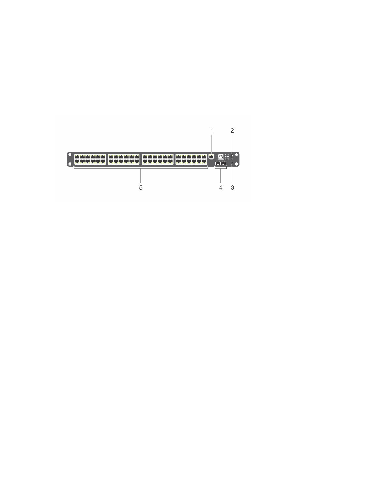
Figure 1. C1048P Front Panel: Ports and Reset Button
1. Console port
The console port provides serial communication using the RS-232 protocol to connect a console
terminal and access the C1048P command-line interface (CLI). To set up a console connection, use
the serial cable (RJ-45 to DB-9 female connectors) shipped with the C9010. The console port
operates as an asynchronous link from 1200 to 115,200 baud. The default settings are 9600 baud
rate, 8 data bits, No Parity, 1 Stop Bit, and No Flow Control.
2. USB port
The Type-A, female USB port supports a USB 2.0-compliant flash memory drive. The C1048P can
read or write to a flash drive formatted as FAT-32. Use a USB flash drive to copy files and images to
the C1048P.
3. Reset button
Access the reset button through a pinhole. To perform a hard reset of the C1048P, insert the tip of a
paper clip or similar tool into the pinhole. When the PE reboots, it re-establishes communication
with an attached C9010, which downloads the latest SW configuration settings.
4. Two 10GbE SFP+ ports
Two SFP+ ports provide 10GbE uplinks to communicate with a C9010. To connect to a C9010
switch, at least one C1048P 10GbE SFP+ port is required. On the C1048P, 10GbE SFP+ ports are
numbered 1 and 2, and only support uplinks to a parent C9010; they cannot be used as data ports.
5. Forty-eight Gigabit Ethernet ports
C1048P Hardware Description
5
Page 6
The 48 Gigabit Ethernet (10BASE-T, 100BASE-TX, 1000BASE-T) RJ-45 ports connect to downstream
servers and edge devices. These ports support auto-negotiation for speed and duplex transmission.
C1048P Gigabit Ethernet ports are numbered 1 to 48.
NOTE: Dell Networking does not recommend that you connect a Gigabit Ethernet port to
another switch or bridge. A loop in the topology may result.
The C1048P automatically detects the difference between crossed and straight-through cables on
RJ-45 ports and automatically chooses the MDI or MDIX configuration to match the other end. The
RJ-45 ports support full-duplex mode 10/100/1000 Mbps speeds on standard Category 5 UTP cable
and Power over Ethernet — PoE (15.4W) and PoE+ (30W).
You can configure up to eight C1048P Gigabit Ethernet interfaces in a port channel that connects to
a downstream edge device.
LED Descriptions: Front Panel
The light emitting diode (LED) displays for PE ID and stack number, temperature, power, system, stack
master, power, fan, and SFP+ link status are on the right side of the C1048P front panel.
10/100/1000BASE-T port LEDs are located above each port.
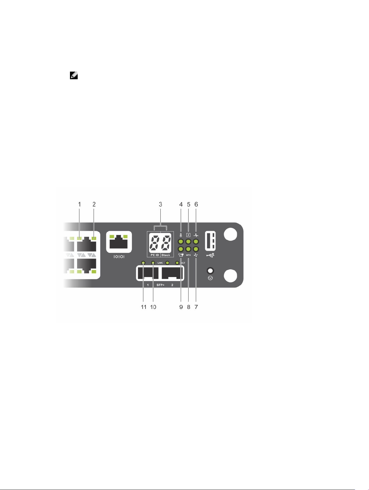
Figure 2. C1048P Front Panel: LEDs
1. 10/100/1000BASE-T port LED: Link 2. 10/100/1000BASE-T port LED: Activity
3. PE ID and Stack ID numbers 4. Temperature LED
5. Power/Locator LED 6. Status LED
7. Fan LED 8. External power supply: Status LED
9. Stack Master/Member LED 10. 10GbE SFP+ uplink port 1: Activity LED
11. 10GbE SFP+ uplink port 1: Link LED
6
C1048P Hardware Description
Page 7

10/100/1000BASE-T Port LEDs
The following table describes 10/100/1000BASE-T port LEDs (items 1 and 2 in Figure 2).
C1048P 10/100/1000BASE-T Port LEDs
LED Description
Link Link speed on port
• Off: No link is up.
• Solid green: The port is operating at 1000 Mbps.
• Solid yellow: The port is operating at 10/100 Mbps.
Activity Data transmission on port
• Off: No transmit/receive activity and PoE power is off.
• Flashing green: The port is actively transmitting/receiving and PoE power is
off.
• Flashing yellow: The port is actively transmitting/receiving and PoE power is
on.
• Solid yellow: No transmit/receive activity and PoE power is on.
System LEDs
The following table describes the system LEDs on the C1048P front panel (items 3 to 11 in Figure 2).
C1048P System LEDs
LED Description
PE ID | Stack When the C1048P is online and connected to a C9010, a scrolling port-
extender ID (PE ID) from 0 to 255 displays in the left, seven-segment LED. A
fixed stack-unit ID number from 0 to 7 displays in the right LED. If the C1048P
is not connected to a C9010, the PE ID LED is blank.
NOTE: The PE ID number displays as a scrolling three-digit number. Each
digit displays briefly followed by a dash ( - ) before the next digit displays.
A blank displays before the three-digit number repeats in the display. For
example, the PE ID 175 displays 1, -, 7, -, 5, followed by a blank before the
PE ID number repeats. Similarly, the PE ID 7 displays as 007: 0, -, 0, -, 7,
followed by a blank.
Temperature status
Temperature
Power/Locator
• Solid green: Normal operation; the temperature is below the minor
threshold of 140°F (60°C).
• Solid red: Warning condition; the temperature exceeds the major threshold
of 167°F (75°C).
Internal power status
• Solid green: Normal operation
• Blinking green: The PE locator is enabled.
• Off: Error condition — There is no power reaching the PE or the PE has a
power failure.
C1048P Hardware Description
7
Page 8

LED Description
System operational status
Status
• Solid green: Normal operation
• Blinking green: The PE is booting.
• Solid red: Critical system error
• Blinking red: Non-critical system error, such as a fan failure
Fan status
Fan
• Solid green: The fan is powered on and is operating at normal RPM speed.
• Solid red: Fan failure
Modular power supply (MPS) status (redundant external power supply)
MPS
• Off: No external (modular) power supply is used.
• Solid green: The PE is receiving power.
• Solid red: An external power supply is detected, but is not receiving power.
Stack master status
Stack Master/
Member
• Off: The PE is operating as the standby unit or a stack member.
• Solid green: The PE is operating as a stack master or in standalone mode.
NOTE: While the C1048P is booting up in standalone or stacking
mode, the Stack Master LED is solid green.
SFP+ LNK (left LED
above port)
SFP+ ACT (right LED
above port)
SFP+ link status
• Off: No data link
• Solid green: Link is up and operating at maximum 10G port speed.
SFP+ activity status
• Off: No data link activity
• Flashing green: Link is up and transmitting/receiving data.
8
C1048P Hardware Description
Page 9

C1048P Back Panel
The back panel of the C1048P PE is shown in the following illustration and described below.
Figure 3. C1048P Back Panel
1. Stack ports: Each C1048P has two fixed mini-SAS (STD) stacking connectors on its back panel. Stack
port 1 is on top; stack port 2 is on the bottom.
You can stack up to eight C1048P PEs using the mini-SAS ports on the back panel. A C1048P PE
supports stacking only with other C1048P PEs. When you connect multiple C1048P PEs using the
stack ports, the PEs operate as a single unit with up to 384 front panel ports. The stack operates and
is managed from a C9010 switch as a single entity.
In a C1048P stack, the Stack Master/Member LED on the front panel indicates operational status
(standalone, stack master, or member unit). For more information about C1048P LED behavior, see
System LEDs.
2. Stack port 1: Activity LED
3. Stack port 1: Link LED
4. Main AC power supply connector: The C1048P PE has an internal 1000-watt power supply that
feeds up to 24 PoE devices at full PoE+ power (850W). PoE power is dynamically allocated.
NOTE: The AC power connector on a C1048P requires an IEC-320-C15 power cable, which is
different than the C13 power cable used on most lower wattage switches.
5. External DC power supply connector: You can connect an additional external power supply
(MPS1000) to provide 1000 watts and full power coverage for all 48 PoE devices (1800W).
6. Fan vents: Two fans are used to cool the C1048P PE.
7. Stack port 2: Activity LED
8. Stack port 2: Link LED
C1048P Hardware Description
9
Page 10

Stack Port LEDs
The stack port LEDs are located to the right of each stack port. The Link LED is above the Activity LED.
Figure 4. C1048P Back Panel: Stack Port LEDs
1. Stack port 1: Activity LED 2. Stack port 1: Link LED
3. Stack port 2: Activity LED 4. Stack port 2: Link LED
Table 2. C1048P Stack Port LEDs
Stack Port LED Description
LNK Stack port link
• Off: No link is up.
• Solid green: Stack link is up.
ACT Stack port activity
• Off: No data link activity.
• Flashing green: Stack link is up and transmitting/receiving data.
Before You Start: Site Preparation
Before installing the C1048P port extender, make sure that your installation site meets these
requirements:
• Clearance: There is adequate space in front of the PE so you can read the LEDs, and adequate space
around and behind the switch for cabling, power connections, and ventilation. The AC power cord
can reach from the power outlet to the utility-panel connector. Airflow around the PE and through
the rear vents is unobstructed.
• Cabling: Route the cabling to avoid sources of electrical noise, such as radio transmitters, broadcast
amplifiers, power lines, and fluorescent lighting fixtures. Make sure that the cabling is safely away from
10
C1048P Hardware Description
Page 11

other devices that might damage the cables. If necessary, allow one RU space between devices to
provide room for cabling.
• Temperature: The ambient temperature around the operating PE is from 0 to 45°C (32 to 113°F).
• Altitude: Altitude at the installation site is below 10,000 feet (3048 m).
• Humidity: The relative humidity around the operating PE is 8% to 85% (non-condensing) with a
maximum humidity gradation of 10% per hour.
• Dust: Install the PE in an environment as free as possible from dust and foreign conductive material
(such as metal flakes from construction activities). Cooling mechanisms, such as fans and blowers in
the switch, can draw dust and other particles causing contaminant buildup inside the chassis, which
can result in system malfunction.
C1048P Hardware Description
11
Page 12

3
Installing the Hardware
To install the C1048P PE, mount it into a 19" wide, EIA-310-E compliant rack. You can install the C1048P
in a 1U 4-post front-rack or 1U 2-post (flush and center) rack configuration. Using a rack mount tray is
optional.
To install the C1048P PE in a rack:
1. (Optional) Install a rack mount tray in a 2- or 4-post rack.
2. Install the C1048P chassis in the rack using mounting brackets.
3. Connect the C1048P to a C9010 switch.
4. (Optional) Set up a C1048P stack by connecting to other C1048Ps.
5. Power up the system.
NOTE: Although Dell Networking strongly recommends that you install the C1048P in a rack, you
may install it on a flat surface as a free-standing device. The surface must be able to support the
weight of the C1048P and the PE cables. The C1048P ships with four self-adhesive rubber pads.
1. When installing the C1048P on a flat surface, attach the self-adhesive rubber pads on each
location marked on the bottom of the switch (unless you are using a rack).
2. Set the C1048P on a flat surface. Make sure that it has proper ventilation by leaving 5 cm (2
inches) on each side and 13 cm (5 inches) at the back.
Before You Start: Rack Safety Considerations
Before installing the C1048P in a rack, review the following rack mounting safety considerations.
WARNING: For complete safety information, read the safety instructions in your Safety,
Environmental, and Regulatory Information booklet before you begin. This document contains a
condensed summary.
• Rack loading — Overloading or uneven loading of racks may result in shelf or rack failure, causing
damage to the equipment and possible personal injury. Stabilize racks in a permanent location before
loading begins. Mount components beginning at the bottom of the rack, then work to the top. Do not
exceed your rack load rating.
• Power considerations — Connect only to the power source specified on the unit. When you install
multiple electrical components in a rack, ensure that the total component power ratings do not
exceed circuit capabilities. Overloaded power sources and extension cords present fire and shock
hazards.
• Elevated ambient temperature — If you install the system in a closed rack assembly, the operating
temperature of the rack environment may be greater than room ambient. Use care not to exceed the
50 degrees C maximum ambient temperature of the switch.
• Reduced air flow — Install the port extender in the rack so that the front-to-back airflow (I/O ports to
PSU) is not obstructed.
12
Installing the Hardware
Page 13

• Reliable earthing — Maintain reliable earthing of rack-mounted equipment. Pay particular attention to
supply connections other than direct connections to the branch circuit; for example, use of power
strips.
• Rack mounting — Do not mount the port extender with the rear panel facing in the downward
position.
Installing a Rack Mount Tray (Optional)
You can use a rack mount tray to support the weight of the C1048P in a 4-post rack. You must order the
tray separately.
To install a rack mount tray in a 4-post rack, follow the instructions provided with the tray kit. Decide on
the desired height to mount the switch in the rack. Position the tray at that height and tighten it to the
rack posts using the screws shipped with the tray (items 1 to 4 in Figure 5).
Figure 5. Example of a Mount Rack Tray
Installing the C1048P in a Rack
You can install the C1048P in a 1 RU 4-post front-rack or 1 RU 2-post (flush and center) rack
configuration. Although the procedure in this section describes C1048P installation in a 1 RU 2-post
front-rack configuration, follow the same steps to install a C1048P in a 1 RU 4-post rack.
WARNING: Never mount the C1048P in a rack that is suspended under a table or desk, or
attached to a wall.
Installing the Hardware
13
Page 14

CAUTION: Before installing the C1048P in a rack, disconnect all cables (if attached) and remove
all self-adhesive pads (if attached) from the underside of the C1048P.
CAUTION: If you plan to install multiple C1048P PEs in a rack, mount the C1048s from the
bottom up. Make sure that the air flow through the ventilation holes on each C1048P is not
obstructed.
To install the C1048P in a rack:
1. Align the holes on the right rack-mount bracket with the holes on the right side (facing you) of the
C1048P.
2. Secure the bracket (item 3 in Figure 6) to the chassis by tightening the screws (item 2 in Figure 6)
provided with the mount bracket.
Figure 6. Attaching Mount Brackets to the C1048P
3. Repeat Steps 1 and 2 to attach the left rack-mount bracket on the C1048P.
4. Mount the C1048P into a 48.26 cm (19 inch) rack. Align the holes on each bracket flange with the
holes on a rack post.
5. Secure the C1048P to the rack using the rack bolts (provided with the mount brackets) or cage nuts
and cage-nut bolts with washers (provided with the rack). Tighten the bolts on the bottom of each
bracket flange first; then tighten the bolts on top (item 1 in Figure 7).
CAUTION: Make sure that the rack bolts provided with the mounting brackets fit the
threaded holes in the rack.
14
Installing the Hardware
Page 15

Figure 7. Mounting the C1048P in a 2-Post Rack
Connecting to a C9010 Switch
The C1048P port extender has two 10G SFP+ ports on the front panel (see Figure 2). The two SFP+ ports
provide 10GbE uplinks to a C9010 switch with SFP+ transceivers. At least one 10GbE SFP+ uplink is
required to connect to a C9010 switch.
NOTE: A C1048P can connect to a C9010 switch only through a 10GbE SFP+ port; a C1048P
cannot connect to a C9010 through a 10/100/1000 Mbps RJ-45 port.
CAUTION: ESD damage can occur if the components are mishandled. Always wear an ESDpreventive wrist or heel ground strap when handling the PE and its components.
WARNING: When working with optical fibres, follow all the warning labels and always wear eye
protection. Never look directly into the end of a terminated or unterminated fibre or connector
as it may cause eye damage.
To connect to a C9010:
1. Position the SFP+ optic correctly over a port. The optic has a key that prevents it from being inserted
incorrectly.
2. Insert the optic into an SFP+ port until it gently snaps into place.
3. Connect one end of an appropriately connectorized fiber-optic cable into the port. Connect the
other end to an SFP+ connector in a C9010 switch.
Installing the Hardware
15
Page 16

Stacking Multiple C1048P Port Extenders
The C1048P supports PE stacking, which allows multiple C1048P units to act as a single port extender.
You can stack up to eight C1048Ps using the stack ports on the back panel.
C1048P stack ports support the Serial Attached SCSI (SAS) protocol and operate as mini-SAS ports. The
C1048P supports stacking only with other C1048P port extenders. The stacked PEs operate as a single
unit with up to 384 front panel ports.
NOTE: If you are installing a stack of C1048Ps, assemble and cable the stack before powering it up.
When you power up a stack for the first time, the C1048P units receive the provisioned
configuration from the parent C9010. A stack master unit is elected based on the highest MAC
address. The master unit may occupy any location in the stack. The Stack Master LED on the front
panel is illuminated on the master unit.
NOTE: Although individual C1048P stack members do not require a separate uplink to a parent
C9010, Dell Networking recommends connecting more than one C1048P stack unit to the C9010
for redundancy. For more information, see
Creating a C1048P Stack
Create a C1048P stack by connecting adjacent units using the mini-SAS stack ports on the back panel.
Figure 8 shows the switches connected in a ring topology, the recommended topology for a C1048P
stack.
1. Install the C1048Ps to be stacked in a rack as described in Installing the C1048P in a Rack.
2. Starting with the C1048P at the top of the stack, connect a mini-SAS cable from a stack port on its
back panel into one of the stack ports on the C1048P directly below it in the rack. You must
separately order mini-SAS cables. If necessary, use a longer (1 meter or 3 meter) mini-SAS cable to
connect the C1048Ps.
3. Connect a mini-SAS cable in the other stack port on the second C1048P and into one of the stack
ports on the third C1048P directly below it. Continue from top to bottom until all C1048Ps in the
rack are connected with a mini-SAS cable.
4. Connect a mini-SAS cable from the bottom C1048P in the stack to the top C1048P to complete a
ring topology.
Connecting to a C9010 Switch.
16
Installing the Hardware
Page 17

Figure 8. C1048P Stack in a Ring Topology
1. C1048P stack 2. Mini-SAS cables attached in a ring topology
The C1048P stack in Figure 8 is connected in a ring topology with the following physical connections
between port extenders. The PEs are numbered Unit 0 to Unit 2. After you power on the stack units, the
Stack Master LED on the C1048P that is elected master displays solid green.
• The bottom mini-SAS port on the top unit is connected to the top mini-SAS port on the middle unit.
• The bottom mini-SAS port on the middle unit is connected to the top mini-SAS port on the bottom
unit.
• The bottom mini-SAS port on the bottom unit is connected to the top mini-SAS port on the top unit.
C1048P Standby
A C1048P stack supports a standby or backup unit that assumes the stack master role if the master unit
fails. When the system detects a stack-master failure, the C9010 initializes the standby unit and it
becomes the stack master. The parent C9010 maintains the running configuration for the stack, which it
pushes to all stack units.
When a PE stack first comes up, the master and standby units are chosen based on the MAC address. By
default, the unit with the highest MAC address becomes the master; the unit with the second highest
MAC address becomes the standby.
Installing the Hardware
17
Page 18

Powering up the C1048P
CAUTION: Read the safety information in the Safety and Regulatory Information manual and the
safety information for C9000 Series switches that connect to the C1048P.
The C1048P has one internal power supply. The AC and DC power connectors are on the back panel (see
Back Panel).
To power up a C1048P, connect it to an AC power source:
1. Using an IEC-320-C15 power cable with safety ground, connect the power cable to the AC main
receptacle on the back panel.
2. Connect the power cable to a grounded AC outlet.
If you connect to a redundant, external DC power supply, use the Dell Networking MPS1000. Connect
the DC power cable from the power supply to the DC receptacle on the back panel.
After you connect the C1048P to a power source, the C1048P boots up. After a successful boot-up, the
temperature, power, system status, and fan LEDs display solid green. The fans adjust to an operational
speed based on the current traffic load. The SFP+ Link LED displays solid green when the uplink to the
parent C9010 is up. The SFP+ Activity LED blinks green when the uplink is transmitting/receiving data.
18
Installing the Hardware
Page 19

4
Dell Networking Support
The Dell Networking Support site provides a range of documents and tools to assist you with using Dell
Networking equipment and mitigating the impact of network outages. Through the support site you can
obtain technical information regarding Dell Networking products, access software upgrades and patches,
download available management software, and manage your open cases. The Dell Networking support
site provides integrated, secure access to these services.
To access the Dell Networking Support site, go to https://www.dell.com/support/. To display information
in your language, scroll down to the bottom of the web page and select your country from the dropdown menu.
• To obtain product-specific information, enter the 7-character service tag or 11-digit express service
code of your C1048P and click Submit.
To view the service tag or express service code on a C1048P, pull out the tag (item 1 in Figure 9) on
the upper left side of the back panel.
• To receive additional kinds of technical support, click Contact Us. On the Contact Information web
page, click Technical Support.
To access C9000 Series documentation, go to https://www.dell.com/manuals/.
To search for drivers and downloads, go to https://www.dell.com/drivers/.
To participate in Dell community blogs and forums, go to https://www.dell.com/community.
Dell Networking Support
19
Page 20

Figure 9. C1048P Service Tag
20
Dell Networking Support
Page 21

Technical Specifications
The following tables describe the technical specifications for the C1048P port extender.
Table 3. Chassis Physical Design
Parameter Specifications
Height 1.7 inches (4.35 cm)
Width 17.32 inches (44 cm)
Depth 15.23 inches (38.7 cm)
Chassis weight
Table 4. Environmental Parameters
Parameter Specifications
Operating temperature 32°F to 113°F (0°C to 45°C)
Maximum operating humidity 95% (non-condensing)
Storage temperature –40°F to 149°F (–40°C to 65°C)
15 lbs (6.8 kg) with factory installed components
44.31 lbs (20.1 kg) fully loaded
5
Storage relative humidity 85% (non-condensing)
Table 5. AC Power Requirements
Parameter Specifications
Nominal input voltage 100-240 VAC 50/60 Hz
Maximum AC power supply input
current (based on 1200W output
for 100/120V lines and 1600W
output for 200/240V lines)
Maximum steady state current
consumption for main PSU with an
MPS1000 external power supply
bank
Maximum power consumption for
main PSU with an MPS1000
external power supply bank
8.9 A @ 100V per AC power supply
7.9 A @ 120V per AC power supply
3.85 A @ 200V per AC power supply
3.55 A @ 240V per AC power supply
110V circuit: ~15.8A
220V circuit: ~7.7A
1,738W @ 110V
1,694W @ 220V
Technical Specifications
21
Page 22

Parameter Specifications
Maximum thermal output 1,017 BTU/hr @ 110V (1.738W - 1,440W PoE = 298W switch power)
22
Technical Specifications
Page 23

6
Agency Compliance
The C1048P complies with the following safety and agency requirements.
European Union EMC Directive Conformance Statement
This product is in conformity with the protection requirements of EU Council Directive 2004/108/EC on
the approximation of the laws of the Member States relating to electromagnetic compatibility. Dell
Networking can not accept responsibility for any failure to satisfy the protection requirements resulting
from a non-recommended modification of this product, including the fitting of non-Dell Networking
option cards.
This product has been tested and found to comply with the limits for Class A Information Technology
Equipment according to CISPR 22/European Standard EN 55022. The limits for Class A equipment were
derived for commercial and industrial environments to provide reasonable protection against interference
with licensed communication equipment.
WARNING: This is a Class A product. In a domestic environment, this device may cause radio
interference, in which case, you may be required to take adequate measures.
European Community Contact
Dell Networking, EMEA - Central
Dahlienweg 19
66265 Heusweiler
Germany
http://www.force10networks.com/german/
Tel: +49 172 6802630
Email: EMEA Central Sales
Agency Compliance
23
Page 24

Japan: VCCI Compliance for Class A Equipment
Figure 10. Japan: VCCI Compliance for Class A Equipment
This is Class A product based on the standard of the Voluntary Control Council For Interference by
Information Technology Equipment (VCCI). If this equipment is used in a domestic environment, radio
disturbance may arise. When such trouble occurs, the user may be required to take corrective actions.
WARNING: Use the AC power cords with Dell Networking equipment only. Do not use Dell
Force10 AC power cords with any unauthorized hardware.
Figure 11. Japan: Warning Label
Korean Certification of Compliance
Figure 12. Korean Certification of Compliance
24
Agency Compliance
Page 25

Figure 13. Korean Package Label
Safety Standards and Compliance Agency Certifications
• CUS UL 60950-1, 2nd Edition or later
• CSA 60950-1-03, 2nd Edition or later
• EN 60950-1, 2nd Edition or later
• EN 60825-1, 1st Edition or later
• EN 60825-1 Safety of Laser Products—Part 1: Equipment Classification Requirements and User’s
Guide
• EN 60825-2 Safety of Laser Products—Part 2: Safety of Optical Fibre Communication Systems
• FDA Regulation 21CFR 1040.10 and 1040.11
• IEC 60950-1, 2nd Edition or later, including all National Deviations and Group Differences
Electromagnetic Compatibility (EMC)
Emissions
• International: CISPR 22, Class A
• Australia/New Zealand: AS/NZS CISPR 22, Class A
• Canada: ICES-003, Issue-4, Class A
• Europe: EN55022 (CISPR 22), Class A
• Japan: VCCI V-3/2011.04 Class A
• USA: FCC CFR47 Part 15, Subpart B, Class A
Immunity
• EN 300 386 v1.5.1 EMC for Network Equipment
• EN55022 Class A
• EN 55024 1998 + A1 + A2 or later
Agency Compliance
25
Page 26

• EN 61000-3-2 Harmonic Current Emissions
• EN 61000-3-3 Voltage Fluctuations and Flicker
• EN 61000-4-2 ESD
• EN 61000-4-3 Radiated Immunity
• EN 61000-4-4 EFT
• EN 61000-4-5 Surge
• EN 61000-4-6 Low Frequency Conducted Immunity
Product Recycling and Disposal
You must recycle or discard this system according to applicable local and national regulations. Dell
Networking encourages owners of information technology (IT) equipment to responsibly recycle their
equipment when it is no longer needed. Dell Networking offers a variety of product return programs and
services in several countries to assist equipment owners in recycling their IT products.
Waste Electrical and Electronic Equipment (WEEE) Directive for Recovery, Recycle and Reuse of IT and Telecommunications Products
Dell Networking switches are labeled in accordance with European Directive 2002/96/EC concerning
waste electrical and electronic equipment (WEEE). The Directive determines the framework for the return
and recycling of used appliances as applicable throughout the European Union. This label is applied to
various products to indicate that the product is not to be thrown away, but rather reclaimed upon end of
life per this Directive.
Figure 14. The European WEEE Symbol
In accordance with the European WEEE Directive, electrical and electronic equipment (EEE) is to be
collected separately and to be reused, recycled, or recovered at end of life. Users of EEE with the WEEE
marking per Annex IV of the WEEE Directive, as shown above, must not dispose of end of life EEE as
unsorted municipal waste, but use the collection framework available to customers for the return,
recycling and recovery of WEEE. Customer participation is important to minimize any potential effects of
EEE on the environment and human health due to the potential presence of hazardous substances in
EEE.
Dell Networking products, which fall within the scope of the WEEE, are labeled with the crossed-out
wheelie-bin symbol, as shown above, as required by WEEE.
For information on Dell Networking product recycling offerings, see the WEEE Recycling instructions on
iSupport. For more information, contact the Dell Networking Technical Assistance Center (TAC) (refer to
Contacting the Technical Assistance Center.
26
Agency Compliance
 Loading...