

Page 1

Dell™ XPS™ 730/730X
Quick Reference Guide
Model DCDO
www.dell.com | support.dell.com
Page 2

Notes, Cautions, and Warnings
NOTE: A NOTE indicates important information that helps you make better use of
your computer.
CAUTION: A CAUTION indicates potential damage to hardware or loss of data if
instructions are not followed.
WARNING: A WARNING indicates a potential for property damage, personal
injury, or death.
____________________
Information in this document is subject to change without notice.
© 2008 Dell Inc. All rights reserved.
Reproduction of these materials in any manner whatsoever without the written permission of Dell Inc.
is strictly forbidden.
Trademarks used in this text: Dell, the DELL logo, XPS, DellConnect, and YOURS IS HERE are
trademarks of Dell Inc.; Intel and Core are either trademarks or registered trademarks of Intel
Corporation in the U.S. and other countries; Microsoft, Windows, Windows Vista, and the Windows
Vista start button logo are either trademarks or registered trademarks of Microsoft Corporation in the
United States and/or other countries; Bluetooth is a registered trademark owned by Bluetooth SIG,
Inc. and is used by Dell under license.
Other trademarks and trade names may be used in this document to refer to either the entities claiming
the marks and names or their products. Dell Inc. disclaims any proprietary interest in trademarks and
trade names other than its own.
Model DCDO
October 2008 P/N C100J Rev. A00
Page 3

Contents
1 Finding Information . . . . . . . . . . . . . . . . . . 7
2 Setting up Your Computer
Front and Back View of the Computer. . . . . . . . . . . 9
Front View
Front I/O Connectors
Back View
Back I/O Connectors
Setting up the Computer
Installing Your Computer in an Enclosure
Connecting to a Network
. . . . . . . . . . . . . . . . . . . . . . 9
. . . . . . . . . . . . . . . . . . . . . 13
. . . . . . . . . . . . . 9
. . . . . . . . . . . . . . . . 12
. . . . . . . . . . . . . . . . 14
. . . . . . . . . . . . . . . . . 17
. . . . . . . . 18
. . . . . . . . . . . . . . . . 20
3 System Configuration . . . . . . . . . . . . . . . 21
Network Configuration (XPS 730 Only) . . . . . . . . . 21
Network Advanced Features
Graphics Configuration
Multiple Displays
NVIDIA SLI and ATI Crossfire Technologies
. . . . . . . . . . . . . . . . . 22
. . . . . . . . . . . . . . . . . . 22
. . . . . . . . . . . . 21
. . . . 23
4 Optimizing Performance . . . . . . . . . . . . . 25
System Setup Based Performance Tuning . . . . . . . 25
Contents 3
Page 4

Software Based Performance Tuning
(XPS 730 Only)
NVIDIA Performance
NVIDIA Monitor
. . . . . . . . . . . . . . . . . . . . . . 26
. . . . . . . . . . . . . . . . 26
. . . . . . . . . . . . . . . . . . . 27
5 Troubleshooting . . . . . . . . . . . . . . . . . . . 29
Diagnostic Tools . . . . . . . . . . . . . . . . . . . . . 29
Dell™ Diagnostics
MP Memory Test
. . . . . . . . . . . . . . . . . 29
. . . . . . . . . . . . . . . . . . 32
Getting More Help
Dell Support 3
Dell PC Tune-Up
Dell PC Checkup
Dell Network Assistant
DellConnect™
Dell Technical Update Service
Diagnostic Indicators
Power Button LED States
Beep Codes
Solving Problems
. . . . . . . . . . . . . . . . . . . . 33
. . . . . . . . . . . . . . . . . . . . 34
. . . . . . . . . . . . . . . . . . . 34
. . . . . . . . . . . . . . . . . . 35
. . . . . . . . . . . . . . . 35
. . . . . . . . . . . . . . . . . . . . 36
. . . . . . . . . . . 36
. . . . . . . . . . . . . . . . . . 36
. . . . . . . . . . . . . . 36
. . . . . . . . . . . . . . . . . . . . . 37
. . . . . . . . . . . . . . . . . . . . 38
Troubleshooting Software and Hardware
Problems
Drive Problems
Memory Problems
Power Problems
Restoring the Operating System
. . . . . . . . . . . . . . . . . . . . . . 38
. . . . . . . . . . . . . . . . . . . 39
. . . . . . . . . . . . . . . . . 40
. . . . . . . . . . . . . . . . . . 41
. . . . . . . . . . . . . 42
Using Microsoft Windows System Restore
Using Dell PC Restore and Dell Factory Image
. . . . . . . . . . . . . . . . . . . . . . . 44
Restore
. . . . . 42
4 Contents
Page 5

Reinstalling the Operating System . . . . . . . . . . . 46
Before you Begin
Reinstalling Windows XP
Reinstalling Windows Vista
Using the Drivers and Utilities Media
Recommended Driver Installation Order
. . . . . . . . . . . . . . . . . . 46
. . . . . . . . . . . . . . 46
. . . . . . . . . . . . 48
. . . . . . . 50
. . . . . . 51
6 Configuring the BIOS. . . . . . . . . . . . . . . . 53
System Setup. . . . . . . . . . . . . . . . . . . . . . . 53
Entering System Setup
System Setup Screens
. . . . . . . . . . . . . . . 53
. . . . . . . . . . . . . . . 54
System Setup Options
Boot Sequence
Option Settings
. . . . . . . . . . . . . . . . . . 55
. . . . . . . . . . . . . . . . . . . . . . 62
. . . . . . . . . . . . . . . . . . . 62
A Appendix . . . . . . . . . . . . . . . . . . . . . . . . . 65
Specifications . . . . . . . . . . . . . . . . . . . . . . 65
Macrovision Product Notice
Contacting Dell
. . . . . . . . . . . . . . . . . . . . . 72
. . . . . . . . . . . . . . 71
Index . . . . . . . . . . . . . . . . . . . . . . . . . . . . . . . 73
Contents 5
Page 6

6 Contents
Page 7

Finding Information
NOTE: Some features or media may be optional and may not ship with your
computer. Some features or media may not be available in certain countries.
NOTE: Additional information may ship with your computer.
Document/Media/Label Contents
Service Tag/Express Service Code
The Service Tag/Express Service Code is
located on your computer.
Drivers and Utilities Media
The Drivers and Utilities media is a CD or
DVD that may have shipped with your
computer.
Operating System Media
The Operating System media is a CD or
DVD that may have shipped with your
computer.
Service Manual
The Service Manual for your computer
can be found at support.dell.com.
• Use the Service Tag to identify your
computer when you use
support.dell.com or contact support.
• Enter the Express Service Code to
direct your call when contacting
support.
• A diagnostic program for your computer.
• Drivers for your computer.
NOTE: Drivers and documentation updates
can be found at support.dell.com.
• Desktop System Software (DSS).
• Readme files.
NOTE: Readme files may be included on
your media to provide last-minute updates
about technical changes to your computer
or advanced technical-reference material
for technicians or experienced users.
• Reinstall your operating system.
• How to remove and replace parts.
• How to configure system settings.
• How to troubleshoot and solve
problems.
Finding Information 7
Page 8

Document/Media/Label (continued) Contents
Dell Technology Guide
The Dell Technology Guide is available at
support.dell.com.
• About your operating system.
• Using and maintaining peripherals.
• Understanding technologies such as
RAID, Internet, Bluetooth
networking, and more.
®
, E-mail,
Microsoft® Windows® License Label
Your Microsoft Windows License is
located on your computer.
Product safety and warranty information
is available as a hardcopy with your
computer.
For additional regulatory and safety
information, see the Regulatory
Compliance Homepage at the following
location:
www.dell.com/regulatory_compliance.
• Provides your operating system product
key.
• Warranty information
• Terms and Conditions (U.S. only)
• Safety instructions
• Regulatory information
• Ergonomics information
• End User License Agreement
8 Finding Information
Page 9
Setting up Your Computer
Front and Back View of the Computer
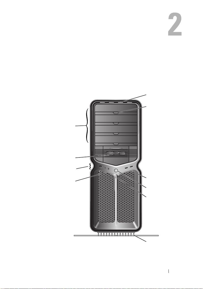
Front View
4
3
2
5
6
1
Setting up Your Computer 9
7
8
9
10
Page 10

1 front panel
LEDs (3)
2 front I/O
connectors
3 3.5-inch drive
bays (2)
Multi-colored LEDs provide illumination for the
front of the computer.
Plug USB and other devices into the appropriate
connectors (see "Front I/O Connectors" on page 12).
Can hold optional devices such as a Media Card
Reader.
NOTE: The Service Tag and Express Service Code are
located on a label inside this bay door.
4 5.25-inch drive
bays (4)
Can hold an optical or SATA hard drive in a
5.25-inch drive bay carrier.
NOTE: The hard drive carrier is only for use in the
5.25-inch drive bays. The floppy-drive/Media Card
Reader and hard drive carriers are not
interchangeable.
5 front panel
LEDs (4)
6 optical drive
tray eject
buttons (4)
7 front panel
LEDs (3)
8 power button Press to turn on the computer.
Multi-colored LEDs provide illumination for the
front of the computer.
Use to eject the drive tray of an optical drive.
NOTE: The optical drive tray eject button is not a
handle. The self-tending doors open automatically
when the eject button is pressed and the drive tray is
ejected.
Multi-colored LEDs provide illumination for the
front of the computer.
CAUTION: To avoid losing data, do not use the
power button to turn off the computer. Instead,
perform an operating system shutdown.
NOTE: The power button can also be used to wake the
system or to place it into a power-saving state.
10 Setting up Your Computer
Page 11

9 hard-drive
activity LED
10 computer stand Attach the computer stand to provide stability to the
The hard drive LED is on when the computer reads
data from or writes data to the hard drive. The LED
may also be on when a device such as your CD player
is operating.
system.
WARNING: The computer stand should be
installed and feet extended at all times to
ensure maximum system stability. Failure to
install the stand could result in the computer
tipping over, potentially resulting in bodily
injury or damage to the computer.
Setting up Your Computer 11
Page 12
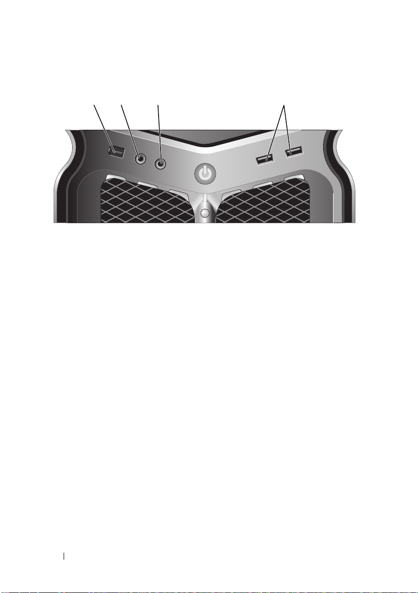
Front I/O Connectors
4213
1 IEEE 1394
connector
2 microphone
connector
3 headphone
connector
4 USB 2.0
connectors (2)
Use the IEEE 1394 connector for high-speed data devices
such as digital video cameras and external storage devices.
Use the microphone connector to attach a personal
computer microphone for voice or musical input into
a sound or telephony program.
Use the headphone connector to attach headphones.
NOTE: Plugging headphones into this connection may disable
rear audio output ports.
Use the front USB connectors for devices that you connect
occasionally, such as flash memory keys, cameras, or
bootable USB devices.
It is recommended that you use the back USB connectors
for devices that typically remain connected, such as printers
and keyboards.
12 Setting up Your Computer
Page 13
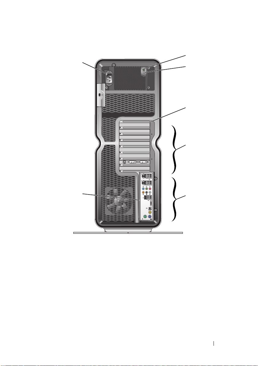
Back View
2
1
3
4
5
7
1 power connector Insert the power cable. The appearance of this connector
may differ from the illustration.
2 Built in Self Test
(BIST) LED
3 BIST switch Use to test the power supply.
4 back panel LEDs Multi-colored LEDs provide illumination for the card slots
Indicates power availability for the power supply.
• Green light—Indicates power availability for the power
supply.
• No light—Indicates no power available for the power
supply or the power supply is not working.
on the back of the computer.
Setting up Your Computer 13
6
Page 14

5 card slots Access connectors for any installed PCI or PCI Express
(PCIe) cards.
NOTE: Some connector slots support full-length cards.
6 back I/O
connectors
7 rear I/O LED
board
Plug USB and other devices into the appropriate connectors
(see "Back I/O Connectors" on page 14).
Multi-colored LEDs provide illumination for the I/O panel
on the back of the computer.
Back I/O Connectors
mouse
connector
keyboard
connector
RCA S/PDIF
connector
optical
S/PDIF
connector
IEEE 1394
connector
rear surround
out
Plug a standard PS/2 mouse into the green mouse
connector. If you have a USB mouse, plug it into
a USB connector.
Plug a standard PS/2 keyboard into the purple keyboard
connector. If you have a USB keyboard, plug it into
a USB connector.
Use the RCA S/PDIF connector to transmit digital
audio without going through an analog audio conversion
process.
Use the optical S/PDIF connector to transmit digital
audio without going through an analog audio
conversion process.
Use the IEEE 1394 connector for high-speed data devices
such as digital video cameras and external storage
devices.
Use the (black) surround sound connector to attach
multichannel-capable speakers.
14 Setting up Your Computer
Page 15

center/LFE
surround out
Use the (orange) subwoofer connector to attach a single
subwoofer.
NOTE: The LFE (Low Frequency Effects) audio channel,
found in digital surround sound audio schemes, carries only
low frequency information of 80 Hz and below. The LFE
channel drives a subwoofer to provide extremely low bass
extension. Systems not using subwoofers can shunt the
LFE information to the main speakers in the surround
sound setup.
line-in
connector
line-out
/headphone
connector
microphone
connector
side surround
sound
connector
Use the (blue) line-in connector to attach a
record/playback device such as a cassette player,
CD player, or VCR.
On computers with a sound card, use the connector on
the card.
Use the (green) line-out connector to attach headphones
and speakers with integrated amplifiers.
On computers with a sound card, use the connector on
the card.
Use the (pink) microphone connector to attach a
personal computer microphone for voice or musical input
into a sound or telephony program.
Use the (silver) side surround connector to attach
additional speakers.
Setting up Your Computer 15
Page 16

1
2
network
adapter
connectors
(2)
Use the network adapter connector to attach your
computer to a network or broadband device.
Connect one end of a network cable to either a network
jack or your network or broadband device, and then
connect the other end of the network cable to the
network adapter connector on your computer.
A click indicates that the network cable has been
securely attached.
NOTE: It is recommended that you use Category 5 wiring
and connectors for your network. If you must use Category
3 wiring, force the network speed to 10 Mbps to ensure
reliable operation.
1 - network
activity LED
2 - link
integrity
LED
Flashes a yellow light when the computer is transmitting
or receiving network data. A high volume of network
traffic may make this LED appear to be in a steady
"on" state.
• Green — A good connection exists between a 10-Mbps
network and the computer.
• Orange — A good connection exists between
a 100-Mbps network and the computer.
• Yellow — A good connection exists between
a 1000-Mbps (1-Gbps) network and the computer.
• Off (no light) — The computer is not detecting a
physical connection to the network.
USB 2.0
connectors
(6)
eSATA
connector
Use the back USB connectors for devices that typically
remain connected, such as printers and keyboards.
NOTE: It is recommended that you use the front USB
connectors for devices that you connect occasionally, such
as flash memory keys, cameras, or bootable USB devices.
Use to connect additional storage devices.
16 Setting up Your Computer
Page 17
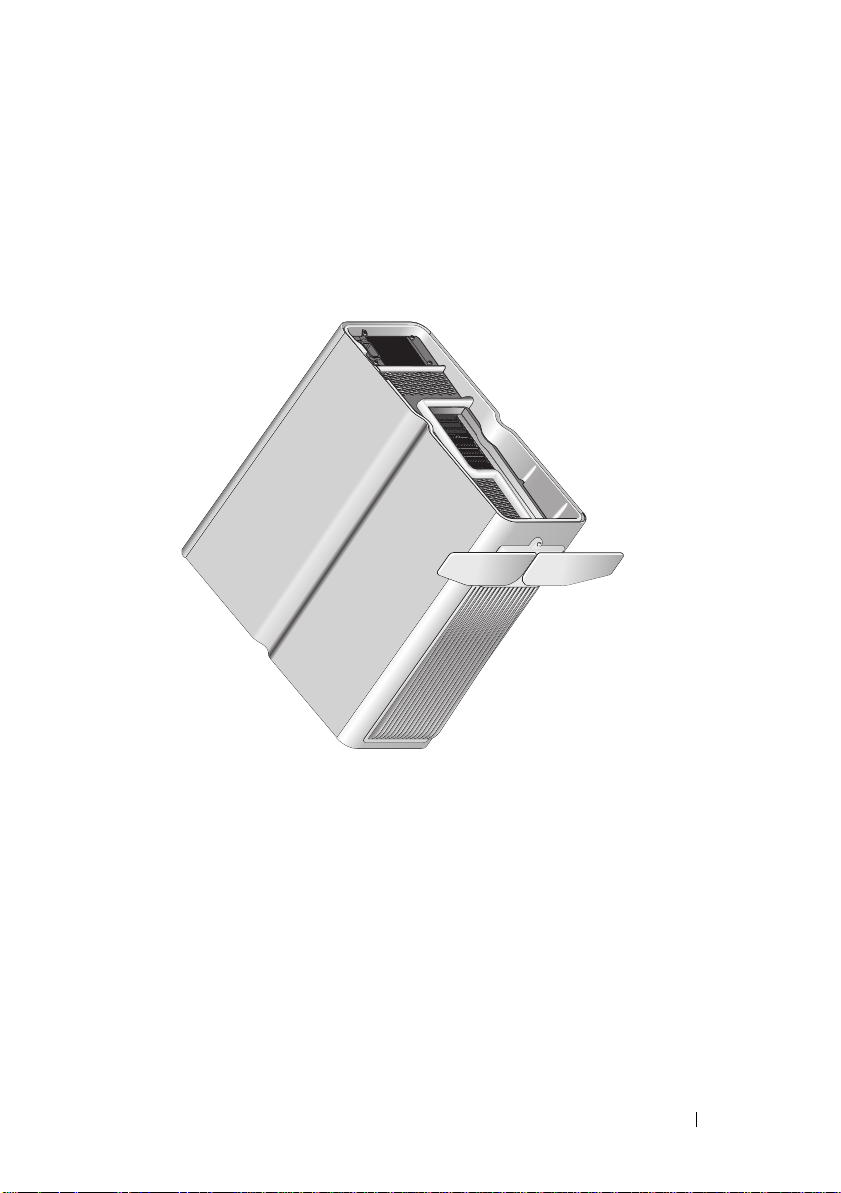
Setting up the Computer
Your computer ships with the computer stand already installed.
With the computer sitting in an upright position, carefully lift the rear of the
computer, and extend the stabilizing feet fully. The extended feet ensure
maximum system stability.
Setting up Your Computer 17
Page 18
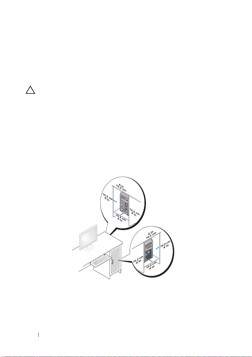
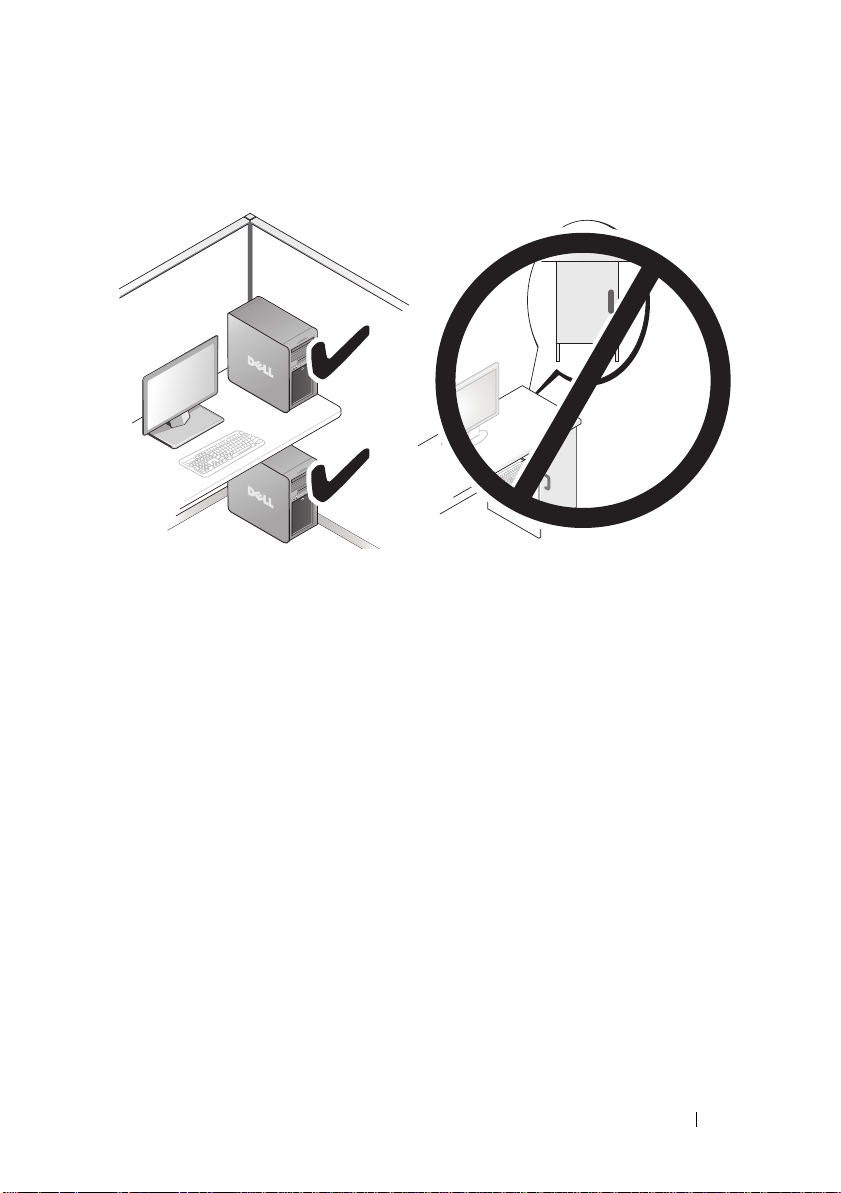
Installing Your Computer in an Enclosure
Installing your computer in an enclosure can restrict the airflow and impact
your computer’s performance, causing it to overheat. It is not recommended
to install the computer in an enclosure. However, if you must install the
computer in an enclosure, refer to the following guidelines:
CAUTION: The operating temperature specifications reflect the maximum
ambient operating temperature. The room’s ambient temperature needs to be
a consideration when installing your computer in an enclosure. For example, if the
ambient room temperature is at 25° C (77° F), depending on your computer’s
specifications, you only have 5° to 10° C (9° to 18° F) temperature margin before
you reach your computer’s maximum operating temperature. For details about your
computer’s specifications, see "Specifications" on page 65.
• Leave a 10.2 centimeter (4 inch) minimum clearance on all vented sides of
the computer to permit the airflow required for proper ventilation.
• If your enclosure has doors, they need to be of a type that allows at least
30% airflow through the enclosure (front and back).
18 Setting up Your Computer
Page 19
• If your computer is installed in a corner on a desk or under a desk, leave at
least 5.1 centimeters (2 inches) of clearance from the back of the
computer to the wall to permit airflow required for proper ventilation.
• Do not install your computer in an enclosure that does not allow airflow.
Restricting the airflow impacts your computer’s performance, possibly
causing it to overheat.
Setting up Your Computer 19
Page 20
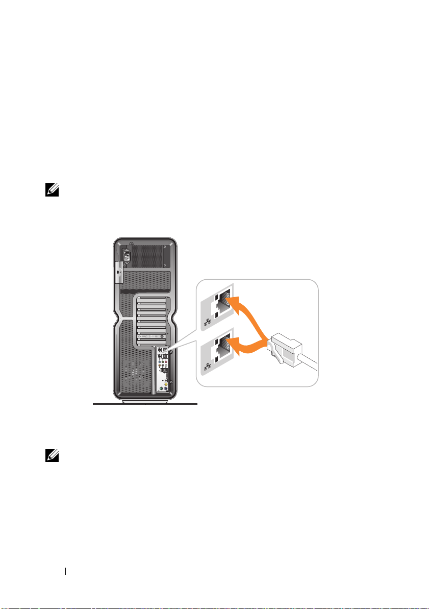
Connecting to a Network
To connect the system to a network:
Connect one end of a network cable to your network device (router,
1
network switch, cable modem/DSL).
2
Connect the other end of the network cable to one of the network adapter
connections on the back of your computer.
A click indicates that the network cable is securely attached.
NOTE: Your computer is configured with two integrated network adapter
connections. These connections support advanced configuration options.
See "Network Advanced Features" on page 21.
If you have an expansion network adapter (PCI, PCIe), plug your network
cable into that adapter.
NOTE: It is recommended that you use Category 5 wiring and connectors for your
network. If you must use Category 3 wiring, force the network speed to 10 Mbps to
ensure reliable operation.
20 Setting up Your Computer
Page 21

System Configuration
NOTE: Some features listed below may not be available or may vary on
a Dell™ XPS™ 730X computer. For more information, go to the Dell Support website
at support.dell.com.
Dell ships your computer to you already configured. This section details
instructions in case you need to re-create or modify your system’s
configuration.
Network Configuration (XPS 730 Only)
Network Advanced Features
The NVIDIA Control Panel offers two tools to help you modify your network
traffic: NVIDIA FirstPacket
You can access these tools via the NVIDIA Control Panel located in the
Windows
NVIDIA FirstPacket
NVIDIA FirstPacket lets you manage the traffic on your system, allowing you
to more effectively manage and improve the performance of networked games
and other applications that are sensitive to network delay (latency), such as
Voice-over-IP (VoIP).
NVIDIA FirstPacket creates an additional transmit queue in the network
driver so that network applications can share a limited resource. Based on user
preference, NVIDIA FirstPacket can expedite transmission for user-approved
network applications.
®
Control Panel.
and TCP/IP acceleration.
System Configuration 21
Page 22

TCP/IP Acceleration
NOTE: Enabling TCP/IP acceleration enhances your network performance but
can cause your network traffic to bypass the firewall because all processes are
off-loaded to the hardware.
TCP/IP acceleration technology is a networking solution that moves the
processing of TCP/IP network traffic from your computer’s CPU to its nForce
hardware resulting in greatly improved system performance.
Graphics Configuration
WARNING: Before you perform any of the procedures in this section, follow the
safety instructions that shipped with your computer.
Dell has configured your graphics sub-system to perform a wide range of
applications.
You may customize your graphic's configuration and performance to fit your
personal needs. This includes enabling multiple monitors, NVIDIA SLI or
ATI Crossfire technologies, and other advanced features.
Multiple Displays
Depending on the video solution you purchased, you may be able to enable
support for two or more displays. The process of enabling multiple display
support involves attaching the additional displays and configuring the video
driver software or control panel to support them.
WARNING: Before you perform any of the procedures in this section, follow the
safety instructions that shipped with your computer.
To attach an additional display:
1
Ensure that the computer and all attached devices are turned off.
2
Connect the new display(s) to the appropriate port on the video card(s).
NOTE: Configurations that include multiple graphics cards ship from the factory
with the video ports on the secondary cards capped by a plastic cover. These
covers may be removed to access these additional video ports.
22 System Configuration
Page 23

Changing the Display Setting to Support Two or More Monitors
After connecting the additional displays you will need to enable them in the
video driver software. The exact steps to do this vary by video card and
installed driver revision, however, in most cases this can be done via the video
card’s Control Panel applet (NVIDIA Control Panel or ATI Catalyst Control
Center). See the Help files for these applets for full instructions and options.
NOTE: When connecting additional display(s) to a video solution that includes
multiple video cards, the added displays will be blank until multi-GPU rendering
technologies (NVIDIA SLI or ATI Crossfire) are disabled.
NVIDIA SLI and ATI Crossfire Technologies
Your computer supports up to three PCIe graphics cards. Two or more
identical graphic cards can be configured to enable NVIDIA SLI (Scalable
Link Interface) or ATI Crossfire technologies. Doing so can increase gaming
and 3D application performance.
Detailed information about the benefits of using these technologies can be
found on the NVIDIA and ATI web sites respectively.
If you selected a multi-card configuration at point of purchase, your
computer includes all of the required hardware to enable NVIDIA SLI or ATI
Crossfire technology.
If you are upgrading from a single card configuration to a dual card
configuration, you will need to purchase the appropriate hardware "bridge" to
link the cards. If you are upgrading from a dual card configuration to a triple
card configuration, you will need to replace the existing dual card bridge with
the appropriate three card bridge to link the cards.
Enabling NVIDIA SLI Technology (XPS 730 Only)
Supporting SLI requires two or more identical NVIDIA SLI-capable graphics
cards, an SLI bridge, and the latest available driver revision.
Enabling NVIDIA SLI technology is done via the NVIDIA Control Panel
applet found in the Windows Control Panel. After opening the applet, select
the Set SLI Configuration option. Choose the Enable SLI technology
option to enable SLI.
NOTE: SLI configurations only support a single display. When enabling SLI
technology, any additional displays will be disabled.
System Configuration 23
Page 24

Enabling ATI Crossfire Technology
Supporting Crossfire technology requires two or more compatible, ATI
Crossfire-capable graphics cards, a Crossfire bridge (for the best performance)
and the latest available driver revision.
Enabling ATI Crossfire technology is done via the ATI Catalyst Control
Center applet found in the Windows Control Panel. After opening the applet
select the Crossfire option. Click the Enable Crossfire option to enable
Crossfire.
NOTE: Crossfire configurations only support a single display. When enabling
Crossfire technology, any additional displays will be disabled.
24 System Configuration
Page 25

Optimizing Performance
NOTE: Some features listed below may not be available or may vary on
a Dell™ XPS™ 730X computer. For more information, go to the Dell Support
website at support.dell.com.
Dell has configured your computer to operate optimally across a wide range of
applications. Depending on the configuration you purchased, the computer
may have been overclocked by the Dell factory to achieve maximum
performance in resource intensive applications including gaming and
multimedia development.
CAUTION: It is not recommended to operate the processor or other system
components beyond the settings configured at the Dell factory. Doing so may
cause system instability, reduced component operating life, or permanent
component damage.
Advanced users who are interested in manually tuning the computer may do
so via the computer's System Setup or by advanced configuration software.
CAUTION: Dell Technical Support verifies the full functionality of the computer at
the factory configured settings. Dell does not provide technical support for any
hardware or software issues arising from operating the system beyond the factory
configured settings.
System Setup Based Performance Tuning
The settings available under the Advanced page of the System Setup provide
users with enhanced access to the options and controls that allow for
computer performance to be manually tuned.
CAUTION: System Setup allows users unrestricted access when setting
performance related parameters. Improperly configuring these settings or
choosing options outside the capabilities of the installed components may
cause system instability, reduced component operating life, or permanent
component damage.
Optimizing Performance 25
Page 26

Software Based Performance Tuning (XPS 730 Only)
Your computer includes components compatible with NVIDIA ESA
(Enthusiast System Architecture). ESA is a PC protocol for real-time
monitoring and control of system’s thermal, electrical, acoustic, and
operating characteristics.
For the advanced user, Dell has pre-installed applications for monitoring and
"tweaking" the performance of installed, ESA compatible components.
For more information about ESA, see nvidia.com/object/nvidia_esa.html
NVIDIA Performance
The NVIDIA Performance application integrates many of the functions
previously available in the NVIDIA nTune application into the Performance
section of the NVIDIA Control Panel.
NOTE: Using the Performance section of the NVIDIA Control Panel may require the
user to accept an End User License Agreement.
Device Settings
When launched, the application detects installed ESA compatible devices
such as CPUs, video cards, memory, system board, and chassis components.
Selecting a component in the Device Settings interface displays the available
settings and options for that component. Advanced users can manually tune
these options to tailor and customize their computer’s performance.
These settings can be saved to profiles to be recalled at a later time.
CAUTION: System Setup allows users unrestricted access when setting
performance related parameters. Improperly configuring these settings or
choosing options outside the capabilities of the installed components may cause
system instability, reduced component operating life, or permanent component
damage.
Dynamic BIOS Access
This section of the NVIDIA Control Panel allows you to change available
BIOS settings via a Windows
settings take effect on the next reboot.
26 Optimizing Performance
®
user interface. Changes to these options and
Page 27

View System Information
This section of the NVIDIA Control Panel allows you to view version
information for the computer and installed drivers. This information can be
saved to a file for further review and also for technical support scenarios.
Profile Policies
The Profile Policies section allows you to define when and how profiles saved
in the Device Settings section are used.
LED Control
Through the LED Control section, you can customize the color and intensity
of the chassis LEDs. You may also create, save, and apply customized LED
effects through this interface.
NVIDIA Monitor
The NVIDIA Monitor application allows you to monitor, track, and log
performance characteristics of compatible components inside your computer.
The data can be used to track the computer’s performance over time as well
as evaluate the effectiveness of a change made to system configuration.
When launched, the application detects installed ESA compatible devices
such as CPUs, video cards, memory, system board, and chassis components.
Selecting a component in the interface displays real-time data for the
available operating characteristics of that component. These characteristics
may include voltages, fan speeds, usage, temperatures, and more.
You can customize the NVIDIA Monitor to:
• Choose key performance characteristics to monitor, graph, and log.
• Set reporting intervals and performance thresholds.
• Configure and log user defined events.
• Customize application key strokes.
Optimizing Performance 27
Page 28

28 Optimizing Performance
Page 29

Troubleshooting
WARNING: Before working inside your computer, read the safety information that
shipped with your computer. For additional safety best practices information, see
the Regulatory Compliance Homepage at www.dell.com/regulatory_compliance.
Diagnostic Tools
Dell™ Diagnostics
If you experience a problem with your computer, perform the checks in
"Solving Problems" on page 38 and run Dell Diagnostics before you contact
Dell for technical assistance.
NOTE: Dell Diagnostics only operate on Dell computers. You can run Dell
Diagnostics from your hard drive or from the Drivers and Utilities media.
Starting Dell Diagnostics From Your Hard Drive
1
Turn on (or restart) your computer.
2
When the DELL logo appears, press <F12> immediately.
NOTE: Keyboard failure may result when a key is held down for extended
periods of time. To avoid possible keyboard failure, press and release <F12> in
even intervals to open the Boot Device Menu.
NOTE: If at any time a message appears stating that no diagnostics
utility partition has been found, run Dell Diagnostics from your Drivers and
Utilities media.
If you wait too long and the operating system logo appears, continue to
wait until you see the Microsoft
your computer and try again.
®
Windows® desktop, then shut down
Troubleshooting 29
Page 30

3
At the Boot Device Menu, use the up- and down- arrow keys or press the
appropriate number on the keyboard to highlight
Boot to Utility Partition
and then press <Enter>.
NOTE: The Quickboot feature changes the boot sequence for the current
boot only. Upon restart, the computer boots according to the boot sequence
specified in system setup.
4
At the Dell Diagnostics Main Menu, left-click with the mouse, or press
<Tab> and then <Enter>, to select the test you want to run.
NOTE: Write down any error codes and problem descriptions exactly as they
appear and follow the instructions on the screen.
5
After all tests are complete, close the test window to return to the Dell
Diagnostics Main Menu.
6
Close the Main Menu window to exit Dell Diagnostics and restart the
computer.
Starting Dell Diagnostics From the Drivers and Utilities Media
1
Turn on (or restart) your computer.
2
Press the eject button on the front of the optical drive to open the drive
tray.
3
Place the
Drivers and Utilities
media in the center of the drive tray, then
press the eject button or gently push on the tray to close it.
4
Restart the computer.
5
When the DELL logo appears, press <F12> immediately.
,
NOTE: Keyboard failure may result when a key on the keyboard is held down
for extended periods of time. To avoid possible keyboard failure, press and
release <F12> in even intervals until the Boot Device Menu appears.
If you wait too long and the Windows logo appears, continue to wait until
you see the Windows desktop, then shut down your computer and try again.
6
At the Boot Device Menu, use the up- and down- arrow keys or press the
appropriate number on the keyboard to highlight
CD-ROM
, and then press <Enter>.
NOTE: The Quickboot feature changes the boot sequence for the current
boot only. Upon restart, the computer boots according to the boot sequence
specified in system setup.
Onboard or USB
30 Troubleshooting
Page 31

7
At the CD-ROM Startup Menu, use the up- and down- arrow keys or press
the appropriate number on the keyboard to highlight
CD-ROM
, and then press <Enter>.
Boot from
If you wait too long and the Windows logo appears, continue to wait
until you see the Windows desktop, then shut down your computer and
try again.
8
Press <1> to select the Dell Diagnostics.
9
At the Dell Diagnostics Menu, press <1> to select Dell Diagnostics
(graphical user interface).
10
At the Dell Diagnostics Main Menu, left-click with the mouse, or press
<Tab> and then <Enter>, to select the test you want to run.
NOTE: Write down any error codes and problem descriptions exactly as they
appear and follow the instructions on the screen.
11
After all tests are complete, close the test window to return to the Dell
Diagnostics Main Menu.
12
Remove the
Drivers and Utilities
media, then close the Main Menu
window to exit Dell Diagnostics and restart the computer.
Dell Diagnostics Main Menu
The following tests can be run from the Dell Diagnostics Main Menu.
Option Function
Express Test Performs a quick test of system devices. The test typically
takes 10 to 20 minutes and requires no interaction on your
part. Run Express Test first to increase the possibility of
tracing the problem quickly.
Extended Test Performs a thorough check of system devices. The test
typically takes an hour or more and periodically requires
your input to answer specific questions.
Custom Test Tests a specific device in the system and can be used to
customize the tests you want to run.
Symptom Tree Lists a number of common symptoms and allows you to
select a test based on the symptom of the problem you
are having.
Troubleshooting 31
Page 32

For any problem encountered during a test, a message appears with an error
code and a description of the problem. Write down the error code and
problem description exactly as it appears and follow the instructions on the
screen. If you cannot resolve the problem, contact Dell (see "Contacting Dell"
on page 72).
NOTE: The Service Tag for your computer is located at the top of each test screen.
When contacting Dell support, have your Service Tag ready.
The following tabs provide additional information for tests run from the
Custom Test or Symptom Tree option:
Tab Function
Results Displays the results of the test and any error conditions
encountered.
Errors Displays error conditions encountered, error codes, and the
problem description.
Help Describes the test and any requirements for running
the test.
Configuration
(Custom Test only)
Displays the hardware configuration for the selected device.
The Dell Diagnostics obtains configuration information for
devices from system setup, memory, and various internal
tests, and it displays the information in the device list in the
left pane of the screen.
NOTE: The device list may not display the names of all the
components installed on your computer or all devices
attached to your computer.
Parameters
(Custom Test only)
Allows you to customize the test, if applicable, by changing
the test settings.
MP Memory Test
The MP (Multi-Processor) Memory Test is a sub-set of the Dell Diagnostics
that runs a thorough, hardware-level test of your system memory. If you
suspect a memory issue, run the MP Memory Test using the following
instructions:
1
Turn on (or restart) your computer.
2
When the DELL logo appears, press <F12> immediately.
32 Troubleshooting
Page 33

If you wait too long and the operating system logo appears, continue to wait
until you see the Microsoft Windows desktop, then shut down your computer
and try again.
3
At the
Boot Device Menu
appropriate number on the keyboard to highlight
and then press <Enter>.
4
Select
Test Memory
Memory, MP Memory is not available.
, use the up- and down-arrow keys or press the
Boot to Utility Partition
by using the <Tab> key. If you do not see Test
Getting More Help
The Dell Support Center provides service, support, and system-specific
information. To obtain detailed information about Dell Support Center and
the available support tools, visit the Consumer Services home page at
support.dell.com
Click the Dell Support Center icon on your computer’s desktop to run
the program and to access the following features:
• Self-help tools such as Dell Support 3, Dell PC Tune-Up, Dell PC
Checkup, and Network Assistant.
• DellConnect for remote, real-time technical support.
• Dell support contact information including e-mail and online chat
addresses, as well as telephone numbers.
• Resources specific to your computer are available under the
Downloads, Upgrades,
The top of the Dell Support Center home page displays your computer’s
model number along with its Service Tag, Express Service Code, and warranty
expiration details. When permissions are given to Dell to use your Service
Tag, additional details about your computer, such as available memory, disk
space, installed hardware, network addresses, modem specifications, installed
security software, and much more are provided.
In addition, using your Service Tag, Dell can link you to the most relevant
dell.com web pages for information about your warranty, ordering accessories,
and details about installing recommended drivers and downloads.
.
Drivers &
and
System Information sections.
,
Troubleshooting 33
Page 34

Dell Support 3
Dell Support 3 is customized for your computing environment. This utility
provides self-support information, software updates, and health scans for your
computer. Use this utility for the following functions:
• Check your computing environment.
• View the Dell Support 3 settings.
• Access the Dell Support 3 help file.
• View frequently asked questions.
• Learn more about Dell Support 3.
• Turn off Dell Support 3.
For more information about Dell Support 3, click the question mark (?) at the
top of the Dell Support 3 window.
To access Dell Support 3:
• Click the Dell Support 3 icon in the notification area of your
Windows desktop.
NOTE: The icon functions vary depending on whether you click, double-
click, or right-click the icon.
OR
Start
• Click the
Settings
button → All Programs→
. Ensure that the
Show icon on the taskbar
Dell Support 3→
option is checked.
Dell Support
NOTE: If Dell Support 3 is not available from the Start menu, go to
support.dell.com and download the software.
Dell PC Tune-Up
The automated or monthly version of Dell PC Tune-Up allows you to choose
the day and time of the month you want your computer "tuned up." A typical
tune-up includes hard drive defragmentation, removal of unwanted and
temporary files, updated security settings, verification of "good" restore
points, and other maintenance activities designed to improve computer
performance and security.
34 Troubleshooting
Page 35

The monthly version is available as an annual subscription and is a feature of
Dell Support 3, a complimentary application that provides real-time health
scans and information on how to maintain your computer (see "Dell Support 3"
on page 34).
Both versions of PC Tune-Up are available to customers in the U.S. and
Canada. To learn more about the monthly version and how easy it is to
keep your computer running at peak performance, visit the PC Tune-Up page
in the Services page at support.dell.com.
Dell PC Checkup
Dell PC Checkup is a troubleshooting and diagnostic tool that provides
customized scanning and testing of your Dell computer. PC Checkup verifies
whether your hardware is working properly and provides automated fixes for
common configuration concerns. It is recommended that you run PC
Checkup on a regular basis or before contacting Dell for assistance.
The application creates a detailed report that Dell technicians can use to
resolve your computer issue quickly.
Dell Network Assistant
Designed specifically for users of Dell computers, the Dell Network Assistant
helps simplify the setup, monitoring, troubleshooting, and repair of your
network.
Dell Network Assistant provides the following features:
• Consolidated setup, alerting, and device status.
• Simplified tracking of networked devices through a visual display of
network status.
• Proactive troubleshooting and repair of network problems.
• Tutorials, setup wizards, and frequently asked questions (FAQs) to
enhance understanding of networking principles.
To access Dell Network Assistant:
Click the Dell Support Center icon on your computer’s desktop.
1
2
Click
Self Help→
Network /Internet→
Network Management
.
Troubleshooting 35
Page 36

DellConnect™
DellConnect is a simple online access tool that allows a Dell service and
support associate to access your computer through an Internet connection,
diagnose the problem, and repair it. The associate works with your permission
under your supervision, and you can work with Dell’s associate during the
troubleshooting session.
To use this service, you must have an Internet connection and your Dell
computer must be under warranty. DellConnect is also available for a fee
through Dell On Call.
To begin a live session with a Dell associate:
1
Click the Dell Support Center icon on your computer’s desktop.
2
Click
Assistance From Dell→
and follow the instructions.
Technical Support→
DellConnect→
Phone
Dell Technical Update Service
The Dell Technical Update service provides proactive e-mail notification of
software and hardware updates for your computer. The service is free and can
be customized for content, format, and how frequently you receive
notifications.
To enroll for the Dell Technical Update service, go to
support.dell.com/technicalupdate.
Diagnostic Indicators
Power Button LED States
The power button LED located on the front of the computer illuminates and
blinks or remains solid to indicate different states:
• If the power button LED is white, the computer is powered on and
operating normally.
• If the power button LED is flashing white, the computer is in standby
mode. Press a key on the keyboard, move the mouse, or press the power
button to resume normal operation.
36 Troubleshooting
Page 37

• If the power button LED is off, the computer is either turned off or is not
receiving power.
– Reseat the power cable into both the power connector on the back of
the computer and the electrical outlet.
– If the computer is plugged into a power strip, ensure that the power
strip is plugged into an electrical outlet and that the power strip is
turned on.
– Bypass power protection devices, power strips, and power extension
cables to verify that the computer turns on properly.
– Ensure that the electrical outlet is working by testing it with another
device, such as a lamp.
– Ensure that the main power cable and front panel cable are securely
connected to the system board (see the
support.dell.com
NOTE: All front panel and back panel LEDs will turn off during sleep states.
).
Service Manual
at
Beep Codes
Your computer may emit a series of beeps during start up. The series of beeps
is called a beep code and can be used to help identify a problem with your
computer.
If your computer emits a series of beeps during start-up:
1
Write down the beep code.
2
Run the Dell Diagnostics to identify the cause (see "Dell™ Diagnostics" on
page 29).
3
See "Contacting Dell" on page 72 for instructions on obtaining technical
assistance.
Troubleshooting 37
Page 38

Code
(repetitive
short beeps)
1 BIOS ROM checksum in progress or
2 No memory detected.
3 Possible motherboard failure.
4 RAM Read/Write failure. Possible
5 RTC power failure. Possible CMOS
6 Video BIOS test failure. Possible
7 CPU Cache test failure (Intel CPU
Description
failure. Possible motherboard failure.
• Chipset error
• Time-of-day clock test failure
• Gate A20 failure
• Super I/O chip failure
• Keyboard controller test failure
memory failure.
battery failure.
video card failure.
only). Possible CPU failure.
Solving Problems
Troubleshooting Software and Hardware Problems
If a device is either not detected during the operating system setup or is
detected but incorrectly configured, you can use the Hardware
Troubleshooter to resolve the incompatibility.
Windows XP:
Click
Start
1
2
Ty p e
and click
hardware troubleshooter
arrow to start the search.
38 Troubleshooting
Help and Support
.
in the
Search
field and click the
Page 39

3
Click
Hardware Troubleshooter
4
In the
Hardware Troubleshooter
conflict on my computer
in the
list, click
, and click
Search Results
list.
I need to resolve a hardware
Next
.
Windows Vista:
1
Click
Start
2
Ty p e
hardware troubleshooter
and click
Help and Support.
in the search field and press
<Enter> to start the search.
3
In the search results, select the option that best describes the problem and
follow the remaining troubleshooting steps.
Battery Problems
WARNING: There is a danger of a new battery exploding if it is incorrectly
installed. Replace the battery only with the same or equivalent type recommended
by the manufacturer. Discard used batteries according to the manufacturer's
instructions.
EPLACE THE BATTERY — If you have to repeatedly reset time and date information
R
after turning on the computer, or if an incorrect time or date displays during start-up,
the
replace the battery (see
battery does not solve the problem, contact Dell.
Service Manual
at
support.dell.com
). If replacing the
Drive Problems
ENSURE THAT MICROSOFT® WINDOWS® RECOGNIZES THE DRIVE —
Windows XP:
• Click
Windows Vista:
• Click Start and click
If the drive is not listed, perform a full scan with your antivirus software to check for
and remove viruses. Viruses can sometimes prevent Windows from recognizing the
drive.
T
• Insert another disc to eliminate the possibility that the original drive is defective.
• Insert a bootable media and restart the computer.
Start
and click
EST THE DRIVE —
My Computer
Computer
.
.
Troubleshooting 39
Page 40

CLEAN THE DRIVE OR DISK
CHECK THE CABLE CONNECTIONS
RUN THE HARDWARE TROUBLESHOOTER — See "Troubleshooting Software and
Hardware Problems" on page 38.
R
UN THE DELL DIAGNOSTICS — See "Dell™ Diagnostics" on page 29.
Hard drive problems
RUN CHECK DISK —
Windo ws XP:
1
Click
Start
and click
2
Right-click
3
Click
4
Click
Local Disk C:
Properties→ Tools→
Scan for and attempt recovery of bad sectors
My Computer
.
Check Now
.
.
and click
Start
.
Windows Vista:
1
Click
Start
2
Right-click
3
Click
Properties→ Tools→
The
User Account Control
computer, click
and click
Local Disk C:
Continue
Computer
.
.
Check Now
.
window may appear. If you are an administrator on the
; otherwise, contact your administrator to continue the
desired action.
4
Follow the instructions on the screen.
Memory Problems
IF YOU EXPERIENCE MEMORY PROBLEMS —
• Reseat the memory modules (see the
that your computer is successfully communicating with the memory.
• Ensure that you are following the memory installation guidelines (see the
at
Manual
support.dell.com
).
• Ensure that the memory you are using is supported by your computer. For more
information about the type of memory supported by your computer, see
"Specifications" on page 65.
• Remove all memory and test one module at a time in the slot closest to the
microprocessor (see the
Service Manual
• Run the MP Memory Test (see "MP Memory Test" on page 32).
• Run the Dell Diagnostics (see "Dell™ Diagnostics" on page 29).
Service Manual
at
support.dell.com
at
support.dell.com
).
) to ensure
Service
40 Troubleshooting
Page 41

Power Problems
ENSURE THAT ALL COMPONENTS AND CABLES ARE PROPERLY INSTALLED AND
SECURELY CONNECTED TO THE SYSTEM BOARD.
A device may be malfunctioning or incorrectly installed.
• Remove and then reinstall all memory modules.
• Remove and then reinstall any extension cards, including graphics cards.
IF THE POWER LIGHT IS OFF
The computer is either turned off or is not receiving power.
• Reconnect the power cable in the power connector on the back of the computer and
the electrical outlet.
• Bypass power strips, power extension cables, and other power protection devices to
verify that the computer turns on properly.
• Ensure that any power strips being used are plugged into an electrical outlet and are
turned on.
• Ensure that the electrical outlet is working by testing it with another device, such as
alamp.
• Ensure that the main power cable and front panel cable are securely connected to the
system board (see the
• Remove and then reinstall any expansion cards, including graphics cards (see the
Service Manual
TEST THE POWER SUPPLY USING THE BUILT- IN-SELF TEST (BIST) — The power
supply includes a built-in-self test to diagnose power supply issues. The test may be
performed with the following steps:
1
Remove all external peripherals.
2
Ensure the system is plugged directly into a working outlet.
3
Press the BIST switch on the back of the power supply. If the LED lights green, the
power supply is operating normally. If the LED does not light, follow these steps to
troubleshoot the issue:
a
Unplug the power cord from the power supply. Open the computer cover.
b
Unplug the power supply cable harness from the power supply.
c
Plug the power cord back into the power supply and retest the power supply using
the BIST switch.
– If the LED lights green, the power supply is operating normally. An internal
component is likely causing the power failure. Contact technical support for further
troubleshooting.
– If the LED does not light green, contact technical support for further
troubleshooting.
Service Manual
at
support.dell.com
at
support.dell.com
).
).
Troubleshooting 41
Page 42

Restoring the Operating System
You can restore your operating system to a previously stable point in the
following ways:
• Microsoft Windows System Restore is a integrated component of
Windows XP and Windows Vista. Microsoft Windows System Restore
returns your computer to an earlier operating state without affecting data
files. Use System Restore as the first solution for restoring your operating
system and preserving data files.
• Dell PC Restore by Symantec (available in Windows XP) and Dell Factory
Image Restore (available in Windows Vista) restores your hard drive to the
operating state it was in when you purchased the computer. These
processes permanently delete all data on the hard drive and remove any
programs installed after you received the computer. Use Dell PC Restore
or Dell Factory Image Restore only if System Restore did not resolve your
operating system problem.
Using Microsoft Windows System Restore
The Windows operating systems provide a System Restore option which
allows you to return your computer to an earlier operating state (without
affecting data files) if changes to the hardware, software, or other system
settings have left the computer in an undesirable operating state. Any
changes that System Restore makes to your computer are completely
reversible.
CAUTION: Make regular backups of your data files. System Restore does not
monitor your data files or recover them.
NOTE: The procedures in this document were written for the Windows default
view, so they may not apply if you set your Dell computer to the Windows
Classic view.
42 Troubleshooting
Page 43

Starting System Restore
Windows XP:
CAUTION: Before you restore the computer to an earlier operating state, save and
close any open files and exit any open programs. Do not alter, open, or delete any
files or programs until the system restoration is complete.
1
Click
Start→
2
Click either
All Programs→
Restore my computer to an earlier time
Accessories→
System Tools→
or
System Restore.
Create a restore
point.
3
Click
Next
and follow the remaining prompts on the screen.
Windows Vista:
Click the
1
2
In the
3
Click
4
In the event that System Restore did not resolve the issue, you may undo
Start
Start Search
NOTE: The User Account Control window may appear. If you are an
administrator on the computer, click Continue; otherwise, contact your
administrator to continue the desired action.
Next
and follow the remaining prompts on the screen.
button.
box, type
System Restore
and press <Enter>.
the last system restore.
Undoing the Last System Restore
CAUTION: Before you undo the last system restore, save and close all open files
and exit any open programs. Do not delete any files or programs until the system
restoration is complete.
Windows XP:
Click
Start→
1
2
All Programs→
Click
Undo my last restoration
Accessories→
and click
System Tools→
Next
.
System Restore
Windows Vista:
Click
1
2
3
Start
In the
Start Search
Click
Undo my last restoration
.
box, type
System Restore
and click
Next
.
and press <Enter>.
.
Troubleshooting 43
Page 44

Using Dell PC Restore and Dell Factory Image Restore
CAUTION: Using Dell PC Restore or Dell Factory Image Restore permanently
deletes all data on the hard drive and removes any programs or drivers installed
after you received your computer. If possible, back up the data before using these
options. Use Dell PC Restore or Dell Factory Image Restore only if the Microsoft
Windows System Restore did not resolve your operating system problem.
NOTE: Dell PC Restore by Symantec and Dell Factory Image Restore may not be
available in certain countries or on certain computers.
Use Dell PC Restore (Windows XP) or Dell Factory Image Restore
(Windows Vista) only as the last method to restore your operating system.
These options restore your hard drive to the operating state it was in when
you purchased the computer. Any programs or files added since you received
your computer-including data files-are permanently deleted from the hard
drive. Data files include documents, spreadsheets, e-mail messages, digital
photos, music files, and so on. If possible, back up all data before using PC
Restore or Factory Image Restore.
Windows XP: Dell PC Restore
Using PC Restore:
Turn on the computer. During the boot process, a blue bar with
1
www.dell.com appears at the top of the screen.
2
When the blue bar appears, press <Ctrl><F11>.
If you do not press <Ctrl><F11> in time, let the computer finish
starting, and then restart the computer again.
CAUTION: If you do not want to proceed with PC Restore, click Reboot.
3
Click
Restore
and click
Confirm
.
The restore process takes approximately 6 to 10 minutes to complete.
When prompted, click
4
NOTE: Do not manually shut down the computer. Click Finish and let the
computer completely reboot.
Finish
to reboot the computer.
44 Troubleshooting
Page 45

5
When prompted, click
Yes
.
The computer restarts. Because the computer is restored to its original
operating state, the screens that appear, such as the End User License
Agreement, are the same ones that appeared the first time the computer
was turned on.
6
Click
Next
.
The System Restore screen appears and the computer restarts.
After the computer restarts, click OK.
7
Windows Vista: Dell Factory Image Restore
Using Factory Image Restore:
Turn on the computer. When the Dell logo appears, press <F8> several
1
times to access the
2
Select
Repair Your Computer
Vista Advanced Boot Options
.
window.
The System Recovery Options window appears.
3
Select a keyboard layout and click
4
To access the recovery options, log on as a local user with administrator
Next
.
level permissions.
5
Click
Dell Factory Image Restore.
NOTE: Depending upon your configuration, you may need to select Dell
Factory Tools, then Dell Factory Image Restore.
The Dell Factory Image Restore welcome screen appears.
Click
Next
6
.
The Confirm Data Deletion screen appears.
CAUTION: If you do not want to proceed with Factory Image Restore, click
Cancel.
7
Click the check box to confirm that you want to continue reformatting the
hard drive and restoring the system software to the factory condition, then
click
Next
.
The restore process begins and may take five or more minutes to
complete. A message appears when the operating system and factoryinstalled applications have been restored to factory condition.
8
Click
Finish
to reboot the system.
Troubleshooting 45
Page 46

Reinstalling the Operating System
To reinstall Windows, you need the following items:
• Dell
•Dell
Before you Begin
Reinstalling your Operating System from media will completely remove all
data from your hard drive. It is important to make a full backup of any files,
internet favorites, photos, documents, movies, music, e-mail archives, or
other media and personal information you wish to keep.
Reinstalling your Operating System from media will also require the user to
reinstall all hardware drivers for their installed components. These drivers and
software may be found on the provided media or under the Drivers and
Downloads section of
Reinstalling your Operating System from media will also require the user to
reinstall all software and applications including any productivity applications
(Microsoft Office), e-mail applications, graphics and audio applications,
media player software, DVD playback software, antivirus, and spyware
utilities. Where applicable, Dell provides media for the reinstallation of these
applications. Some utilities and software may be found under the Drivers and
Downloads section of
Operating System
Drivers and Utilities
NOTE: The Dell Drivers and Utilities media contains drivers that were installed
during the assembly of the computer. Use the Dell Drivers and Utilities media to load
any required drivers. Depending on the region from which you ordered your
computer, or whether you requested the media, the Dell Drivers and Utilities media
and Operating System media may not ship with your computer.
media
media
support.dell.com
support.dell.com
.
.
Reinstalling Windows XP
The reinstallation process can take 1 to 2 hours to complete. After you
reinstall the operating system, you must also reinstall the device drivers, virus
protection program, and other software.
CAUTION: The Operating System media provides options for reinstalling
Windows XP. The options can overwrite files and possibly affect programs that are
installed on your hard drive. Therefore, do not reinstall Windows XP unless a Dell
technical support representative instructs you to do so.
46 Troubleshooting
Page 47

NOTE: It is strongly recommended that you use the provided Dell Operating System
media when reinstalling the operating system. The Dell media includes all
necessary drivers required to install Windows XP. Using retail or third party media
may require the user to provide additional drivers during the installation of the
operating system.
1
Insert the Windows XP CD in the CD drive, and restart your computer.
2
After the initial installation files are loaded, press the <Enter> key to set
up Windows XP.
3
In the
Windows XP Licensing Agreement
, read the license agreement.
Press the <Page Down> key to scroll through the agreement.
4
Press the <F8> key to accept the terms and conditions specified in the
license agreement.
NOTE: By default, Unpartitioned Space is highlighted. If any other
partitions appear that were not previously created by you, they may include
a PC Restore partition (2.7 to 4.75 GB) or a MediaDirect (1.2 GB) partition
for portable computers.
5
In the
Windows XP Setup
partition screen, choose a partition to install
the Operating System. You may also choose to remove a partition or create
a new partition for the installation.
6
The
Windows XP Setup
the NTFS file system
screen appears with
Format the partition using
highlighted; press the <Enter> key, or the <F> key
if applicable, to format the partition.
7
After formatting the partition,
Windows XP Setup
will copy the necessary
files to the partition and restart the computer.
NOTE: Do not press any keys if the message Press any key to boot from the
CD appears.
The amount of time it takes to complete the above process varies,
depending on the speed and size of the computer.
8
Click the
The
9
Type your name in the
Organization:
Next
button on the
Personalize Your Software
Name:
field, if applicable, and click
Regional and Language Options
screen appears.
field and your organization's name in the
Next
. The Computer Name
screen appears.
Troubleshooting 47
window.
Page 48

10
Type the computer name in the Computer Name: field if you want to
change it from the name provided.
NOTE: For Windows XP Professional Edition users, type a password in the
Administrator Password: field and then type the same password in the
Confirm Password: field.
11
Click
Next
.
The Modem Dialing Information screen appears.
NOTE: Only computers with a modem installed will see the Modem Dialing
Information section. If your computer does not have a modem, skip to step 15
for Date and Time Settings.
12
Click to select the correct country/region for the
are you in now?
13
Type your area code in the
box and the number in the
what is it?
14
Click to select one of the items below for
location uses:
box.
What area code (or city code) are you in now?
If you dial a number to reach an outside line,
box, if applicable.
box:
What Country/Region
The phone system at this
– Tone dialing if your phone service uses tone dialing.
– Pulse dialing if your phone service uses pulse dialing.
15
Click
Next
. The
16
Verify that the correct
Date and Time Settings
Date, Time
screen appears.
, and
Time Zone
appear, and click
The Networking Settings screen appears after several minutes.
17
Click to select
Typical
, and click
Next
.
Next
.
NOTE: If available, click Skip to skip the networking setup section.
For Windows XP Professional users, click to select No, this computer is
not on a network, and click Next.
18
The computer restarts and continues with the setup program.
Reinstalling Windows Vista
The reinstallation process can take 1 to 2 hours to complete. After you
reinstall the operating system, you must also reinstall the device drivers
(see "Using the Drivers and Utilities Media" on page 50), virus protection
program, and other software.
48 Troubleshooting
Page 49

CAUTION: The Operating System media provides options for reinstalling
Windows Vista. The options can overwrite files and possibly affect programs that
are installed on your hard drive. Therefore, do not reinstall Windows Vista unless
a Dell technical support representative instructs you to do so.
1
Insert the
2
Restart (or power on) the computer.
3
Press the <F12> key as soon as the keyboard lights up.
The
Operating System media into the DVD drive of the computer.
Boot Menu
appears.
A window appears that says
4
Press a key on the keyboard.
5
Click
Language, Time, Currency and Keyboard Method
Next
.
6
On the
7
Review the terms and click
8
On the
(advanced)
9
On the
options (advanced)
10
Click
11
On the
Windows Vista Installation
Which type of installation do you want?
.
Where do you want to install Windows
.
Disk 0 Partition 1
If you delete this partition, all data stored on it will be
permanently deleted
12
On the
13
When prompted to select the size of the file, select the size, and then
click
14
Click to select the partition, and then click
15
On the
Where do you want to install Windows
Apply
.
If you format this partition, all data stored on it will be
permanently deleted
On the
Where do you want to install Windows
Press any Key to Boot from a CD or DVD
page, click
I accept the license terms
Install Now
to proceed.
window, click
window, click
, and then click
Delete
.
window, click OK.
window, click
Format
.
window, click OK.
window, click
, and then click
.
Custom
Drive
New
.
Next
.
.
16
Installing Windows
The
NOTE: Your computer will restart several times during installation.
The
Setup
window appears.
window appears.
Troubleshooting 49
Page 50

17
Select a user name, password, and picture for your user account.
18
On the
window, click
19
On the
Recommended Settings
The
20
Click to select your time zone, and then click
The
21
Click
Choose a computer name and choose a desktop background
Next
.
Help Protect Windows automatically
window, click
Use
.
Review your time and date settings
Thank you
Start
window appears.
.
window appears.
Next
.
Using the Drivers and Utilities Media
Once you have successfully reinstalled your operating system, you need to
load the appropriate drivers for your installed hardware. These drivers are
included on the Drivers and Utilities media.
1
When the Windows desktop displays, insert the
media.
2
When the Drivers and Utilities installation program starts you may be
prompted to install the software. If so, follow the prompts on the screen.
3
In the
Welcome Dell System Owner
NOTE: The Drivers and Utilities media displays drivers only for hardware that
came installed in your computer. If you installed additional hardware, the
drivers for the new hardware might not be displayed by the Drivers and
Utilities media. If those drivers are not displayed, exit the Drivers and Utilities
media program. For drivers information, see the documentation that came
with the device.
4
A message appears, stating that the
screen, click
Drivers and Utilities
hardware in your computer.
5
The drivers that are used by your computer are automatically displayed in
the
My Drivers-The Drivers and Utilities media has identified these
components in your system
window.
Drivers and Utilities
Next
.
media is detecting
50 Troubleshooting
Page 51

Recommended Driver Installation Order
NOTE: The exact drivers that you have to install will depend on the operating
system you choose to install and the exact hardware configuration of your
computer. If you are unsure what hardware you have installed or are unsure of
which exact drivers to load, contact Technical Support.
When installing the drivers and utilities for your hardware, it is recommended
that you install them in the following order.
Critical Drivers
1
a
Desktop System Software (may be located under the Utilities section)
b
Chipset Drivers
2
Core Component Drivers
a
Video Card Driver
b
NIC / Modem
c
Audio Card Drivers
3
Peripheral Drivers - (Install these drivers as applicable)
a
Mouse / Keyboard
b
Camera
c
TV Tuner
d
Bluetooth
4
Utilities
Dell Support Center
Troubleshooting 51
Page 52

52 Troubleshooting
Page 53

Configuring the BIOS
System Setup
The System Setup options allow you to:
• Change the system configuration information after you add, change,
or remove any hardware in your computer.
• Set or change a user-selectable option.
• Read the current amount of memory or set the type of hard drive installed.
Before you use System Setup, it is recommended that you write down the
current System Setup information for future reference.
CAUTION: Do not change the settings in System Setup unless you are an expert
computer user. Certain changes can cause your computer to work incorrectly.
Entering System Setup
1
Turn on (or restart) your computer.
2
When the DELL™ logo appears, press <F2> immediately.
NOTE: Keyboard failure may result when a key on the keyboard is held down
for extended periods of time. To avoid possible keyboard failure, press and
release <F2> in even intervals until the System Setup screen appears.
If you wait too long and the operating system logo appears, continue to
wait until you see the Microsoft
your computer and try again.
®
Windows® desktop, then shut down
Configuring the BIOS 53
Page 54

System Setup Screens
The System Setup window displays current or changeable configuration
information for your computer. Information is divided into five areas: the
menu field, the options list, the active options field, the help field, and key
functions.
Menu — Appears on top of the System Setup window. This field provides
a menu to access to the System Setup options. Press the left-arrow key and
right-arrow key to navigate. As a Menu option is highlighted, the Options
List, displays the options that define the hardware installed on you
computer.
Options List —
Appears on the left side
of the System Setup
window. The field lists
features that define the
configuration of your
computer, including
installed hardware,
power conservation, and
security features.
Scroll up and down the
list with the up- and
down-arrow keys. As an
option is highlighted,
the Options Field
displays the option’s
current and available
settings.
Options Field —
Appears on the right side
of Options List and
contains information
about each option in the
Options List. In this
field you can view
information about your
computer and make
changes to your current
settings.
Press <Enter> to make
changes to your current
settings. Press <ESC>
to return to the Options
List.
NOTE:
Not all settings listed
in the Options Field are
changeable.
Help — Appears on
the right side of the
System Setup
window and contains
help information
about the option
selected in Options
List.
Key Functions — Appears below the Options Field and lists keys and their
functions within the active System Setup field.
54 Configuring the BIOS
Page 55

System Setup Options
NOTE: Depending on your computer and installed devices, the items listed in this
section may not appear, or may not appear exactly as listed.
NOTE: The System Setup options listed below are for a Dell XPS™ 730 computer.
The options may vary for a Dell XPS 730X computer. For more information, see the
Service Manual on the Dell Support website at support.dell.com.
Main
Date Displays the system date.
Time Displays the system time.
System Info Displays the system model name.
BIOS Info Display the BIOS revision.
Service Tag Displays the system Service Tag.
Express
Service Code
Asset Tag Displays the asset tag.
Memory
Installed
Memory
Available
Memory Speed Displays the memory speed.
Memory Channel
Mode
Memory
Technology
Processor Type Displays the type of processor.
Processor
Speed
Processor L2
cache
Displays the Express Service Code.
Displays the total memory size.
Displays the memory available in the system.
Displays the memory channel modes.
•Single
•Dual
Displays the type of memory used in the system.
Displays the speed of the processor.
Displays the processor L2 cache size.
Configuring the BIOS 55
Page 56

Advanced
CPU
Configuration
Allows you to enable or disable the CPU features that enhance
the performance of the system.
• CPU Multiplier—The CPU multiplier multiplied by the
front-side bus (FSB) clockspeed determines the core speed
of the processor.
CPU core clock = FSB Frequency/4 x CPU multiplier
• C1E Enhanced Halt State—If enabled, CPU power
consumption is reduced when the CPU is idle. This is triggered
by the operating system executing the halt instruction.
(Enabled/Disabled)
Execute Disable Bit—When disabled, forces the XD feature
•
flag to always return 0.
• Virtualization —When enabled, a virtual machine monitor
(VMM) can utilize the additional hardware capabilities
provided by Vanderpool Technology.
SpeedStep—If enabled, the CPU clock speed and CPU core
•
voltage are adjusted dynamically based on the CPU load.
(Enabled/Disabled)
• CPU Core 0 through CPU Core 3—Enables CPU Core 0, 1, 2,
and 3. (Enabled/Disabled)
(Enabled/Disabled)
(Enabled/Disabled)
56 Configuring the BIOS
Page 57

Advanced (continued)
Integrated
Peripherals
Allows you to enable or disable the integrated devices and ports
on your system.
• Halt On—Sets the type of error to halt the system during POST.
(All errors, No errors, All errors but keyboard errors)
• Boot Up NumLock Status—Sets the power-on state for
NumLock. (On/Off)
• Fast Boot—Enables Fast Boot. When enabled, allows the BIOS
to skip certain tests during POST which decreases the amount
of time needed to boot the system. (Enabled/Disabled)
• Drive A—Specifies the capacity and physical size of a diskette
drive.
• USB Controller—Enables the USB controller.
(Enabled/Disabled)
• USB Keyboard Support—Enables the USB keyboard support.
(Enabled/Disabled)
• USB Mouse Support—Enables the USB mouse support.
(Enabled/Disabled)
• HD Audio—Enables the HD audio setting. (Enabled/Disabled)
• Onboard LAN Controller—Enables the onboard LAN controller
setting. (Enabled/Disabled)
• Onboard LAN1 Controller—Enables the onboard LAN1
controller setting. (Enabled/Disabled)
• Onboard LAN Boot ROM—Enables the function of LAN boot
ROM. (Enabled/Disabled)
• IEEE1394 Controller—Enables the IEEE1394 controller
setting. (Enabled/Disabled)
Configuring the BIOS 57
Page 58

Advanced (continued)
IDE/SATA
Configuration
Enables or disables a user to define or change any values related
to IDE or SATA devices such as hard drives, optical drives, and so
on connected to the computer.
• HDD S.M.A.R.T Capability—Enables the hard drive
S.M.A.R.T. setting. (Enabled/Disabled)
• Serial-ATA Controller—Enables the SATA controller Setting.
(All enabled, Disabled, SATA-0, SATA-1)
• RAID Config—Enables RAID configuration.
(Enabled/Disabled)
• PATA Channel 0 Master—Enables auto-detection of the drive
size and head on this channel.
• PATA Channel 0 Slave—Enables auto-detection of the drive
size and head on this channel.
• SATA 1-6—Enables auto-detection of the drive size and head
on this channel.
58 Configuring the BIOS
Page 59

Advanced (continued)
Overclock
Configuration
Enables you to set the system clock mode. Displays the following
parameters and current value for each parameter:
• CPU Frequency, MHz—Displays the current setting.
• CPU Multiplier—Displays the current setting.
• FSB-Memory Clock Mode—Allows you to set the system clock
mode:
– Auto—Sets the FSB and memory speed automatically.
– Linked—Allows you to enter the FSB and speed manually.
The Memory speed changes proportionally.
– Unlinked-—Allows you to enter the FSB and memory speed
manually.
• FSB-Memory Ratio—Allows you to set the FSB-memory ratio to
Auto, 1:1, 5:4, 3:2, or Sync Mode.
• FSB (QDR), MHz—Allows you to adjust the CPU FSB
frequency. The FSB (QDR) that displays in the Actual column
reflects the actual frequency that will take effect on reboot.
Enter a value between 400 and 2600.
• MEM (DDR), MHz—Allows you to adjust the memory
frequency. The MEM (DDR) that displays in the Actual
column reflects the actual frequency that will take effect
on reboot.
• PCIe x16_1, MHz—Allows you to select the frequency for
PCIe x16 slot 1.
• PCIe x16_2, MHz—Allows you to select the frequency for
PCIe x16 slot 2.
• PCIe x16_3, MHz—Allows you to select the frequency for
PCIe x16 slot 3.
• Dynamic ODT—Enables dynamic ODT (on-die termination).
• Memory Timing Setting—Allows you to edit timing settings for
your memory. (Advanced)
Configuring the BIOS 59
Page 60

Advanced (continued)
Overvoltage
Configuration
Security
Supervisor
Password Is
User Password Is Specifies whether a user password has been assigned.
Set Supervisor
Password
Set User
Password
Enables you to configure the voltage of the CPU core, FSB,
memory voltage, and chipset voltage.
• CPU Core—Allows you to set the voltage level for the CPU core
(CPU VID).
• CPU FSB—Allows you to set the voltage level for the CPU FSB
(CPU VTT).
• Memory—Allows you to set the voltage level for DRAM.
• Chipset Voltage—Allows you to set the core voltage level for
nForce SPP.
• nForce MCP—Allows you to set the core voltage level for nForce
MCP.
• nForce MCP Aux—Allows you to set the auxiliary voltage level
for nForce MCP.
• GTLVREF Lane 1—Allows you to add extra voltage to the CPU
GTLVREF Lane 1 voltage level.
Specifies whether a supervisor password has been assigned.
Allows you to set a supervisor password.
Allows you to set a user password. You cannot use the user
password to enter the BIOS setup during POST.
60 Configuring the BIOS
Page 61

Power
ACPI Suspend
Type
AC Recovery Specifies the behavior of the system after recovering from
Remote Wake Up Notifies the computer to turn on when a user tries to access the
Wake-Up By
Ring
Auto Power On Enables you to set an alarm to turn on the computer
Boot
Hard Disk Boot
Priority
First Boot
Device through
Third Boot
Device
Boot Other
Device
Specifies the Advanced Configuration and Power Interface
(ACPI) suspend type. ACPI is a power management
specification which enables the operating system to control the
amount of power given to each device attached to the
computer. The default is S3.
a power loss.
• On—The computer turns on after it recovers from a power
failure.
• Off—The computer remains powered off.
• Last—The computer returns the power state it was in before
the power failure.
computer through the LAN.
Notifies the computer to turn on when an incoming call is
detected on the modem.
automatically.
Sets the hard drive boot priority. The items displayed are
dynamically updated according to the hard drives detected.
Sets the boot device sequence. Only the bootable devices that
are connected to the computer are listed as options.
Enables you to boot from other devices such as a memory key.
Exit
Exit Options Provides options to Exit Saving Changes, Exit Discarding
Changes, Load Setup Default, and Discard Changes.
Configuring the BIOS 61
Page 62

Boot Sequence
This feature allows you to change the boot sequence for the bootable devices
installed on your computer.
Option Settings
•
Diskette Drive —
If the floppy disk in the drive is not bootable, if no floppy disk is in the drive,
or if there is no floppy drive installed in the computer, the computer attempts
to boot from the next bootable device in the boot sequence.
•
Hard Drive
drive. If no operating system is on the drive, the computer attempts to
boot from the next bootable device in the boot sequence.
CD Drive
•
CD is in the drive, or if the CD has no operating system, the computer
attempts to boot from the next bootable device in the boot sequence.
•
USB Flash Device —
restart the computer. When
corner of the screen, press <F12>. The BIOS detects the device and adds
the USB flash option to the boot menu.
NOTE: To boot to a USB device, the device must be bootable. To ensure that your
device is bootable, check the device documentation.
NOTE: An error message is generated only after the computer attempts to boot
from every device in the boot sequence and no operating system is found.
The computer attempts to boot from the floppy drive.
— The computer attempts to boot from the primary hard
— The computer attempts to boot from the CD drive. If no
Insert the memory device into a USB port and
F12 = Boot Menu
appears in the upper-right
Changing Boot Sequence for the Current Boot
You can use this feature, for example, to tell the computer to boot from the
CD drive so that you can run the Dell Diagnostics on the Drivers and Utilities
media, but you want the computer to boot from the hard drive when the
diagnostic tests are complete. You can also use this feature to restart your
computer to a USB device such as a floppy drive, memory key, or CD-RW drive.
NOTE: If you are booting to a USB floppy drive, you must first set the floppy drive to
OFF in System Setup.
1
If you are booting to a USB device, connect the USB device to a USB
connector (see "Back View" on page 13).
2
Turn on (or restart) your computer.
62 Configuring the BIOS
Page 63

3
When the DELL logo appears, press <F12> immediately.
NOTE: Keyboard failure may result when a key on the keyboard is held down
for extended periods of time. To avoid possible keyboard failure, press and
release <F12> in even intervals until the Boot Device Menu appears.
If you wait too long and the operating system logo appears, continue to
wait until you see the Microsoft Windows desktop, then shut down your
computer and try again.
4
At the
Boot Device Menu
, use the up- and down- arrow keys or press the
appropriate number on the keyboard to highlight the device that is to be
used for the current boot only, and then press <Enter>.
For example, if you are booting to a USB memory key, highlight
Device
and press <Enter>.
NOTE: To boot to a USB device, the device must be bootable. To make sure
that your device is bootable, check the device documentation.
Changing Boot Sequence for Future Boots
1
Enter System Setup (see "Entering System Setup" on page 53).
2
Use the arrow keys to highlight the
Boot
menu option and press <Enter>
to access the menu.
NOTE: Write down your current boot sequence in case you want to restore it.
3
Press the up- and down- arrow keys to move through the list of devices.
4
Press the spacebar to enable or disable a device (enabled devices have a
check mark).
5
Press plus (+) or minus (–) to move a selected device up or down the list.
USB Flash
Configuring the BIOS 63
Page 64

64 Configuring the BIOS
Page 65

Appendix
Specifications
NOTE: Offerings may vary by region. For more information regarding the
configuration of your computer, click Start→ Help and Support and select the option
to view information about your computer.
Processor Dell™ XPS™ 730 Dell XPS 730X
Processor type Intel
Cache at least 4 MB at least 8 MB
Memory Dell XPS 730 Dell XPS 730X
Type 800 MHz and faster DDR3
Memory connectors four three
Memory capacities 512 MB, 1 GB, and 2 GB DDR3: 1 GB, 2 GB, and 4 GB
Minimum memory 1 GB 3 GB
Maximum memory 8 GB 12 GB
®
Core™2 Duo
(Performance dual core)
Intel Core2 Quad
(Performance quad core)
Intel Core2 Extreme
(Extreme performance
quad core)
unbuffered SDRAM;
SLI memory
Intel Core i7
Intel Core i7 Extreme Edition
1066 MHz and faster DDR3
unbuffered SDRAM; XMP
memory
XMP: 1 GB and 2 GB
NOTE: The amount of memory available depends on the
operating system installed.
Appendix 65
Page 66

Computer Information Dell XPS 730 Dell XPS 730X
Chipset
Northbridge
Southbridge
BIOS chip (NVRAM) 8 Mb 8 Mb
NIC two integrated network
Video Dell XPS 730 Dell XPS 730X
Type dual PCIe x16 Generation 2
Audio
Type HDA 7.1 channel, Realtek 888
Expansion Bus Dell XPS 730 Dell XPS 730X
Bus type PCI Express x1 and x16
PCI
nForce 790i SLI
nForce 790i SLI SPP
nForce 790i SLI MCP
interfaces capable of
10/100/1000 Mbps
communication
single PCIe x16 Generation 1
codec
PCI 32-bit
Intel X58
Intel 36s IOH
Intel ICH10
two integrated network
interfaces capable of
10/100/1000 Mbps
communication
dual PCIe x16 Generation 2
single PCIe x16 Generation 2
HDA 7.1 channel, Realtek 888
codec
PCI Express x1 and x16
PCI 32-bit
Connector
Connector size
Connector data
width (maximum)
Bus speed
PCI Express x1
Connector
Connector size
Connector data
width (maximum)
66 Appendix
two one
124 pins 124 pins
32 bits 32 bits
33 MHz 33 MHz
one x1 two x1
36 pins 36 pins
1 PCI Express lane 1 PCI Express lane
Page 67

Expansion Bus Dell XPS 730 Dell XPS 730X
Bus throughput
PCI Express x16
Generation 2
Connector
Connector size
Connector data
width (maximum)
Bus throughput
PCI Express x16
Generation 1
Connector
Connector size
Connector data
width (maximum)
Bus throughput
x1 slot bidirectional speed —
2.5 Gbps
two x16 three x16
164 pins 164 pins
16 PCI Express lanes 16 PCI Express lanes
x16 slot bidirectional speed —
80 Gbps
one x16 N/A
164 pins
16 PCI Express lanes
x16 slot bidirectional speed —
40 Gbps
x1 slot bidirectional speed —
2.5 Gbps
x16 slot bidirectional speed
— 80 Gbps
Appendix 67
Page 68

Drives Dell XPS 730 Dell XPS 730X
Available devices
Serial ATA (SATA) hard
drive
Floppy drive
SATA Blu-ray Disc (BD)
writer
SATA BD/DVD combo
drive
SATA DVD+/-RW drive
CD-RW/DVD combo drive
Media Card Reader
Externally accessible two 3.5-inch drive bays
four 5.25-inch drive bays
Internally accessible four 3.5-inch drive bays
for hard drives
✓ = Supported; ✘ = Not supported
Connectors Dell XPS 730 Dell XPS 730X
External connectors
✓
✓
✓
✓
✓
✓
✓
two 3.5-inch flex bays
four 5.25-inch drive bays
four 3.5-inch drive bays
for hard drives
✓
✘
✓
✓
✓
✘
✓
IEEE 1394a
Network adapter
PS/2 (keyboard and mouse)
USB
Audio
Drive
68 Appendix
front and back-panel
6-pin serial connectors
two RJ45 connectors two RJ45 connectors
two 6-pin mini-DIN two 6-pin mini-DIN
two front-panel, six backpanel, and four internal
USB 2.0–compliant
connectors
HDA 7.1 channel sound
on rear; S/PDIF out on
rear; headphone and
microphone jacks on
front, internal S/PDIF
one eSATA port one eSATA port
front and back-panel
6-pin serial connectors
two front-panel, six
back-spanel, and four
internal
USB 2.0–compliant
connectors
HDA 7.1 channel sound
on rear; S/PDIF out on
rear; headphone and
microphone jacks on
front, internal S/PDIF
Page 69

Connectors (continued) Dell XPS 730 Dell XPS 730X
System board connectors
IDE drive
Serial ATA
Floppy drive
Fan
PCI
PCI Express x1
PCI Express x16
eSATA
Controls and LEDs
Power control push button
Power LED white light — Blinking white in sleep state; solid
Hard-drive access LED white
Link integrity LED (on
integrated network adapter)
Activity LED (on integrated
network adapter)
Standby power LED blue AUXPWR on the system board.
one 40-pin connector N/A
six 7-pin connectors eight 7-pin connectors
one 34-pin connector N/A
one 4-pin connector; five
3-pin headers
two 124-pin connectors one 124-pin connector
two 36-pin connectors two 36-pin connectors
three 164-pin connectors three 164-pin connectors
one internal eSATA one internal eSATA
white for power-on state.
• Green — A good connection exists between
a 10-Mbps network and the computer.
• Orange — A good connection exists between
a 100-Mbps network and the computer.
• Yellow — A good connection exists between a
1000-Mbps (1-Gbps) network and the computer.
• Off (no light) — The computer is not detecting
a physical connection to the network.
• Yellow blinking light — Indicates activity on the
network.
• Off (no light) — Indicates no activity on the
network.
one 4-pin connector; five
3-pin headers
Appendix 69
Page 70

Controls and LEDs (continued)
Front panel LEDs ten multi-colored LEDs provide illumination for the
front of the computer.
Back panel LEDs four multi-colored LEDs provide illumination for the
I/O panel on the back of the computer.
Power
DC power supply
Wa t ta g e
Voltage (see the safety
instructions that shipped
with your computer)
Optional UPS
Backup battery 3-V CR2032 lithium coin cell
Physical
Height
Without stand
With stand
Width
Without stand
With stand
Depth 59.4 cm (23.4 inches)
We ig ht
Typical configuration
Maximum configuration
WARNING: To reduce the risk of fire, electric
shock, or injury, do not overload an electrical
outlet, power strip, or convenience receptacle.
The total ampere rating of all products plugged
into an electrical outlet, power strip, or other
receptacle should not exceed 80 percent of the
branch circuit rating.
1 kW
wide-ranging power supply—90 V to 265 V at
50/60 Hz
Output rating must be 1.5kW or higher
55.5 cm (21.9 inches)
57.2 cm (22.5 inches)
21.9 cm (8.6 inches)
35.6 cm (14.0 inches)
21.7 kg (47.8 lb)
25.6 kg (56.4 lb)
70 Appendix
Page 71

Environmental
Temperature
Operating
Storage
Relative humidity 20% to 80% (noncondensing)
Maximum vibration
Operating
Storage
Maximum shock
Operating
Storage
Altitude
Operating
Storage
Airborne contaminant
10° to 35°C (50° to 95°F)
–40° to 65°C (–40° to 149°F)
0.25 G at 3 to 200 Hz at 0.5 octave/min
0.5 G at 3 to 200 Hz at 1 octave/min
bottom half-sine pulse with a change in velocity of
20 inches/sec (50.8 cm/sec)
27-G faired square wave with a velocity change of
200 inches/sec (508 cm/sec)
–15.2 to 3048 m (–50 to 10,000 ft)
–15.2 to 10,668 m (–50 to 35,000 ft)
G2 or lower as defined by ISA-S71.04-1985
Macrovision Product Notice
This product incorporates copyright protection technology that is protected
by method claims of certain U.S. patents and other intellectual property
rights owned by Macrovision Corporation and other rights owners. Use of this
copyright protection technology must be authorized by Macrovision
Corporation, and is intended for home and other limited viewing uses only
unless otherwise authorized by Macrovision Corporation. Reverse engineering
or disassembly is prohibited.
Appendix 71
Page 72

Contacting Dell
You can contact Dell through the Internet and by phone:
• For support through the web, go to
• For worldwide support through the web, use the
Country/Region
menu near the bottom of the page, or see the web
addresses listed in the following table.
NOTE: In certain countries, support specific to Dell™ XPS™ computers is available
at a separate telephone number listed for participating countries. If you do not see
a telephone number listed that is specific for XPS computers, you may contact Dell
through the support number listed and your call will be routed appropriately.
• For support by phone, use the phone number and codes provided in the
following table. If you need assistance in determining which codes to use,
contact a local or an international operator.
• The contact information provided was deemed correct at the time that
this document went to print and is subject to change.
Support Type Area Codes,
Phone
Web Support
Online Chat
Community Forums
Gaming / XPS Forums
support.dell.com
Choose A
support.dell.com/support/
supportrequests/create.aspx
support.dell.com/support/
topics/global.aspx/support/
.
Local Numbers, and
Toll-Free Numbers
Web and E-mail Address
1-800-232-8544
gen/chat
dellcommunity.com/
supportforums
dellcommunity.com/
supportforums/
?category.id=Gaming
72 Appendix
Page 73

Index
B
beep codes, 37
BIOS, 53
Boot Sequence, 62
boot sequence
changing, 62-63
option settings, 62
booting
to a USB device, 62
C
cards
slots, 14
CDs
operating system, 7
Check Disk, 40
computer
beep codes, 37
conflicts
software and hardware
incompatibilities, 38
connectors
headphone, 12, 15
IEEE, 12, 14
keyboard, 14
line-in, 15
line-out, 15
mouse, 14
network adapter, 16
power, 13
sound, 15
USB, 12, 16
contacting Dell, 72
D
Dell
contacting, 71-72
Dell Network Assistant, 35
Dell Support 3, 34
Dell Technology Guide, 8
DellConnect, 36
diagnostics
beep codes, 37
documentation
Dell Technology Guide, 8
Service Manual, 7
E
End User License Agreement, 8
ergonomics information, 8
error messages
beep codes, 37
ESA, 26
Index 73
Page 74

H
N
hard drive
problems, 40
hardware
beep codes, 37
conflicts, 38
Hardware Troubleshooter, 38
headphone
connector, 12, 15
I
IEEE
connectors, 12, 14
IRQ conflicts, 38
K
keyboard
connector, 14
M
memory
problems, 40
mouse
connector, 14
network
connector, 16
NVIDIA ESA, 26
NVIDIA FirstPacket, 21
NVIDIA Performance, 26
O
operating system
reinstalling, 7
Operating System CD, 7
P
phone numbers, 72
power
button, 10
connector, 13
problems, 41
power light
conditions, 41
problems
beep codes, 37
conflicts, 38
hard drive, 40
memory, 40
power, 41
power light conditions, 41
74 Index
processor
type, 65
Page 75

R
regulatory information, 8
S
system setup, 53
entering, 53
options, 55
screens, 54
safety instructions, 8
Service Manual, 7
settings
system setup, 53
software
conflicts, 38
sound connectors
line-in, 15
line-out, 15
specifications
computer information, 66
connectors, 68
controls and lights, 69
drives, 68
environmental, 71
expansion bus, 66
memory, 65
physical, 70
power, 70
processor, 65
technical, 65
video, 66
T
TCP/IP acceleration, 22
telephone numbers, 72
troubleshooting
conflicts, 38
Hardware Troubleshooter, 38
U
USB
booting to devices, 62
connector, 16
connectors, 12
W
warranty information, 8
Windows XP
reinstalling, 7
support
contacting Dell, 71-72
System Setup, 25, 53
Index 75
Page 76

76 Index
 Loading...