

Dell Alienware M17x User Manual

ALIENWARE® M17x MOBILE MANUAL

Notes, Cautions, and Warnings
NOTE: A NOTE indicates important information that helps you make better
use of your computer.
CAUTION: A CAUTION indicates either potential damage to hardware or
loss of data and tells you how to avoid the problem.
WARNING: A WARNING indicates a potential for property damage, personal
injury, or death.
e contents herein are subject to change without notice.
© 2009 Dell Inc. All rights reserved.
Reproduction of these materials in any manner whatsoever without the prior
written permission of Dell Inc. is strictly prohibited.
Trademarks used in this manual: Alienware, AlienRespawn, AlienFX, and the
AlienHead logo are trademarks or registered trademarks of Alienware Corporation.
Dell is a trademark of Dell Inc. Microsoft, Windows, Windows Vista, and Windows
Vista start button logo are either trademarks or registered trademarks of Microsoft
Corporation in the United States and/or other countries. Intel is a registered
trademark and Core is a trademark of Intel Corporation in the U.S. and other
countries. AMD is a trademark of Advanced Micro Devices, Inc. Blu-ray Disc is a
trademark of the Blu-ray Disc Association. Bluetooth is a registered trademark
owned by Bluetooth SIG, Inc. Computrace and Absolute are registered trademarks
of Absolute Software Corporation.
Other trademarks and trade names may be used in this manual to refer to either
the entities claiming the marks and names or their products. Dell Inc. disclaims
any proprietary interest in trademarks and trade names other than its own.
Model: P01E P/N: P776N Rev. A00 FEBRUARY 2009
02
/
02

CONTENTS
INTRODUCTION ........................................................ 5
CHAPTER 1: SETTING UP YOUR NOTEBOOK ..............................6
Before Setting Up Your Notebook ..................................6
Setting Up Your Alienware Mobile .................................. 7
CHAPTER 2: GETTING TO KNOW YOUR NOTEBOOK ....................... 9
Examining Your Notebook ........................................ 10
Front View Features ...............................................11
Back View Features................................................11
Left View Features ............................................... 12
Right View Features .............................................. 12
Top View Features................................................ 13
Bottom View Features............................................ 13
Status LEDs ..................................................... 14
Power Button ....................................................14
Touch Controls................................................... 15
Function Keys ................................................... 15
Battery Pack ......................................................17
Power Management.............................................. 19
CHAPTER 3: CONNECTING DEVICES.....................................20
Connecting External Displays ..................................... 21
Connecting Printers ..............................................23
Connecting USB Devices..........................................23
Connecting FireWire (IEEE 1394) Devices ..........................23
CHAPTER 4: USING YOUR NOTEBOOK ..................................24
Alienware Command Center ......................................24
Stealth Mode ....................................................25
Using Removable Media and Cards................................25
Using the Optical Drive ...........................................25
Using the Integrated Webcam ....................................25
Using the Wireless Control........................................25
Working With RAID ...............................................26
Conguring the BIOS .............................................27
CHAPTER 5: INSTALLING ADDITIONAL OR REPLACEMENT
COMPONENTS ..................................................32
Before You Begin .................................................33
Upgrading/Replacing Memory ....................................34
Upgrading/Replacing Hard Drives .................................37
CHAPTER 6: TROUBLESHOOTING ......................................40
Basic Hints and Tips..............................................40
Backup and General Maintenance.................................41
Software Diagnostic Tools ........................................42
Answers to Common Problems ...................................44
CHAPTER 7: SYSTEM RECOVERY ........................................51
AlienRespawn v2.0...............................................52
Recovery Options ................................................52
Password Protection .............................................53
AlienRespawn v2.0 Disc ..........................................54
CHAPTER 8: BASIC SPECIFICATIONS....................................55
03
/
03

APPENDIX A: GENERAL AND ELECTRICAL SAFETY PRECAUTIONS .........58
APPENDIX B: DETAILED SAFETY, ENVIRONMENTAL, AND
REGULATORY INFORMATION.....................................60
APPENDIX C: WARRANTY AND SUPPORT INFORMATION ................. 74
APPENDIX D: DELL SOFTWARE LICENSE AGREEMENT....................88
APPENDIX E: CONTACTING ALIENWARE .................................90
APPENDIX F: IMPORTANT INFORMATION.................................91
04
/
04

INTRODUCTION
Dear Valued Alienware Customer,
Welcome to the Alienware family. We are thrilled to include you among the growing
number of savvy high-performance mobile users.
e Alienware technicians who have crafted your machine have made certain that
your high-performance mobile is properly optimized and performs to its fullest
potential. We build machines with one single unwavering purpose: Build It As If
It Were Your Own. e technicians will not rest until your new machine meets or
exceeds our very demanding criteria!
We have tested your machine extensively in order to ensure that you enjoy the
highest levels of performance. In addition to a standard burn-in period, your
system has been evaluated using real-world tools such as synthetic performance
benchmarks.
INTRODUCTION
INTRODUCTION
We invite you to share your experience with your new high-performance mobile
with us, so please do not hesitate to either e-mail or call Alienware with any
questions or concerns. e entire sta shares your enthusiasm for new technology
and we hope that you enjoy using your new mobile as much as Alienware enjoyed
building it for you.
Sincerely,
Alienware Sta
05
/
05

CHAPTER 1: SETTING UP YOUR NOTEBOOK
CHAPTER 1: SETTING UP YOUR NOTEBOOK
CHAPTER 1: SETTING UP YOUR NOTEBOOK
Before Setting Up Your Notebook
Congratulations on the purchase of your Alienware® M17x!
Please read all safety and setup instructions before plugging in your new notebook.
Begin by carefully opening the box and removing all components that were shipped
to you. Before setting up your notebook or components, be sure to inspect all items
for any physical damage that may have occurred during shipment. Be sure to
report any damaged items to customer service immediately upon receiving your
shipment. You must report shipping damage within the rst 5 days of receiving the
shipment or your damage report will not be honored.
Before setting up your notebook or components, please refer to the included invoice
to verify that all items ordered are present. Report any missing components to
customer service within 5 days of receiving the shipment. Anything reported
missing after the rst 5 days of receiving a shipment will not be honored. Some of
the most common items to check for include:
Notebook and AC adapter with power cord•
Microsoft CD-Key located at the bottom of the notebook•
Monitor with power cord and video cable (if ordered)•
Keyboard (if ordered)•
Mouse (if ordered)•
Multimedia speakers and sub-woofer (if ordered)•
Joystick controllers (if ordered)•
You may also need a small athead and/or Phillips head screwdriver for connecting
peripheral cables to the notebook.
06
/
06
CHAPTER 1: SETTING UP YOUR NOTEBOOK
Product Documentation and Media
e documentation that ships with your Alienware® mobile is designed to provide
answers to many of the questions that may arise as you explore your new notebook’s
capabilities. You may refer to the documentation for technical information or general
use as needed to answer questions in the future, or aid you in nding answers and
solutions. e media included with your notebook is referenced in some sections
of the documentation and may be needed to complete certain tasks. As always, our
Technical Support sta is available to assist you.
Location and Positioning of Your Notebook
WARNING: Do not place the notebook near or over a radiator or heating
vent. If all or parts of your notebook are placed in a cabinet, ensure that
adequate ventilation is provided. Do not place the notebook in a humid
location or in any area where the notebook may be exposed to rain or
water. Be careful not to spill liquid of any kind on or into the notebook.
When positioning your notebook, be sure that:
It is placed on a surface that is both level and stable. •
e power and other cable connectors are not jammed between the notebook •
and a wall – or any other object.
Nothing obstructs airow in front of, behind, or below the notebook.•
e notebook has enough room so that optical drives and other external •
storage drives can be easily accessed.
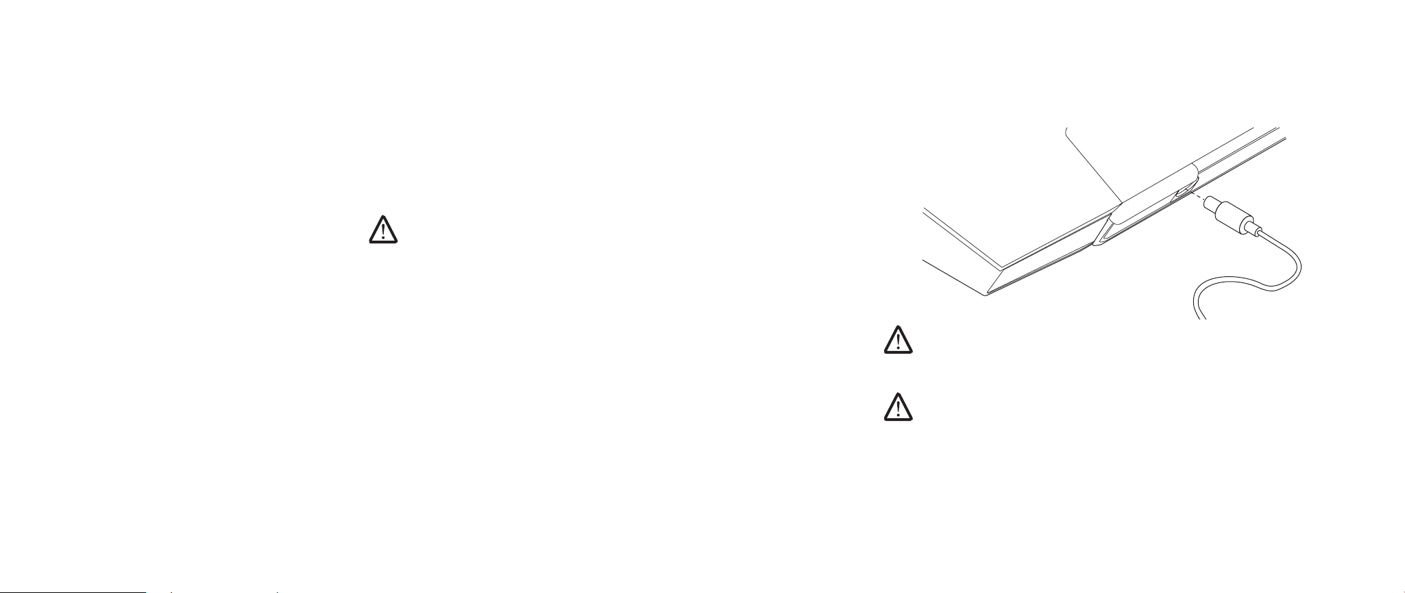
Setting Up Your Alienware Mobile
Connect the AC Adapter to the Back of Your Notebook STEP 1.
WARNING: e AC adapter works with electrical outlets worldwide.
However, power connectors and power strips vary among countries. Using
an incompatible cable or improperly connecting the cable to a power strip
or electrical outlet may cause re or equipment damage.
NOTE: e 240 W AC adapter must be plugged in to the notebook for maximum
gaming performance.
07
/
07

CHAPTER 1: SETTING UP YOUR NOTEBOOK
Press the Power ButtonSTEP 2.
Windows VistaSTEP 3.
®
Setup
CAUTION: Do not interrupt the operating system’s setup process. Doing
so may render your notebook unusable.
If you selected Windows Vista operating system while ordering, your notebook
is precongured with Windows Vista. To set up Windows Vista for the rst time,
follow the instructions on the screen. ese steps are mandatory and may take up
to 15 minutes to complete. e screens will take you through several procedures
including accepting license agreements, setting preferences, and (optionally)
setting up an Internet connection.
Connecting to the Internet
If you do not set up your Internet connection during the Vista Setup,
Click 1. Start (Windows Vista
®
logo) > Control Panel > Network and Internet.
Click 2. Connect to the Internet.
Follow the instructions on the screen. 3.
For more help and information about creating a new Internet connection, click
Start (Windows Vista® logo) > Help and Support and perform a search for “Internet
connection.”
Connecting to a Home Network
Click 1. Start (Windows Vista® logo) > Control Panel > Network and Internet.
Click 2. Connect to a network located in Network and Sharing Center section.
Follow the instructions on the screen.3.
For more help and information about networking, click Start (Windows Vista®
logo) > Help and Support > Table of Contents and click Networking from the list
of help topics.
08
/
08

CHAPTER 2: GETTING TO KNOW YOUR NOTEBOOK
CHAPTER 2: GETTING TO KNOW YOUR
CHAPTER 2: GETTING TO KNOW YOUR NOTEBOOK
is chapter provides information about your new notebook to familiarize you with
its various features and get you up and running quickly.
NOTEBOOK
09
/
09

Examining Your Notebook
Before you start using your notebook, you need to get acquainted with your
notebook’s main features and interfaces:
1
2
3
4
5
12
11
10
6
CHAPTER 2: GETTING TO KNOW YOUR NOTEBOOK
1 left digital array microphone 7 touch capacitive strip
2 webcam activity indicator 8 right side of the notebook
3 webcam 9 front of the notebook
4 right digital array microphone 10 palm rest
5 edge-to-edge LCD with
11 left side of the notebook
integrated webcam and digital
array microphone
6 back of the notebook 12 keyboard
7
9
8
010
/
010
CHAPTER 2: GETTING TO KNOW YOUR NOTEBOOK
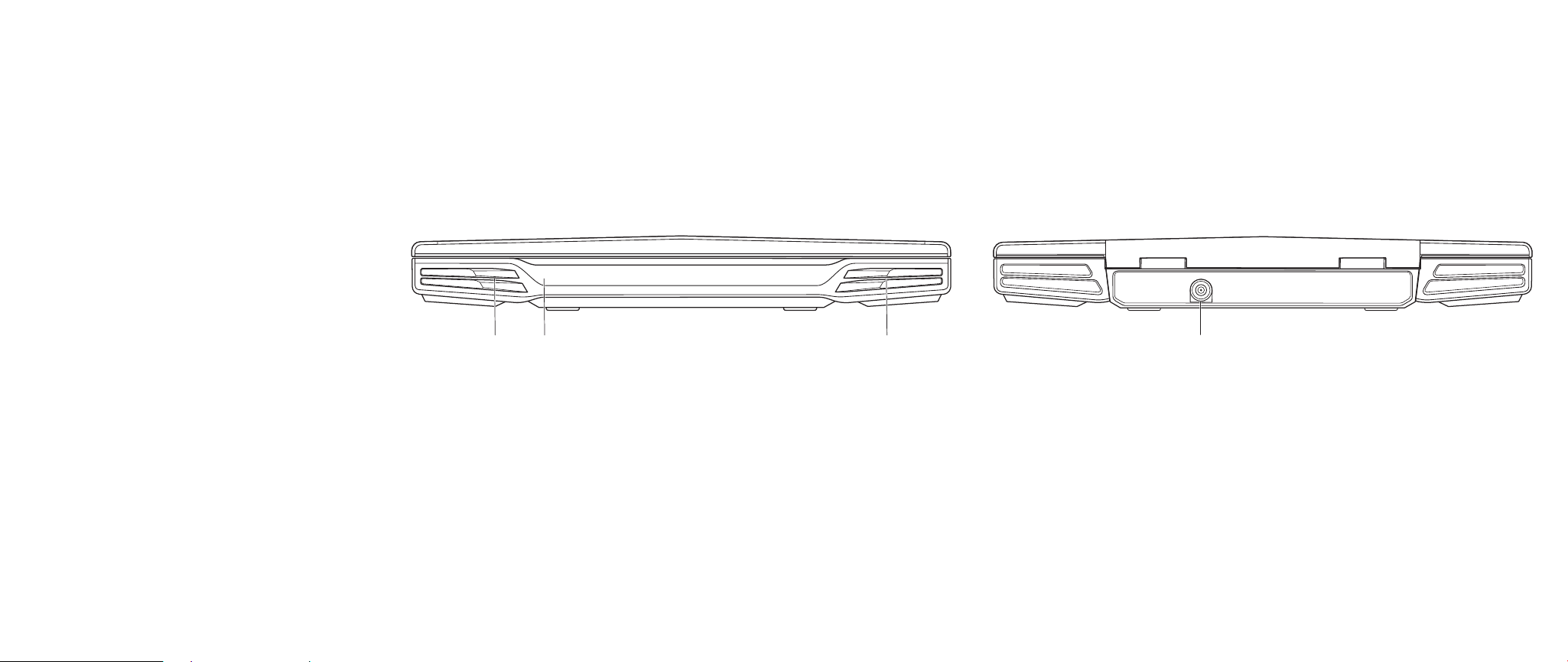
Front View Features
1
1 left speaker 3 right speaker
2 consumer IR underneath
2 3
Back View Features
1
1 AC adapter connector
011
/
011
CHAPTER 2: GETTING TO KNOW YOUR NOTEBOOK
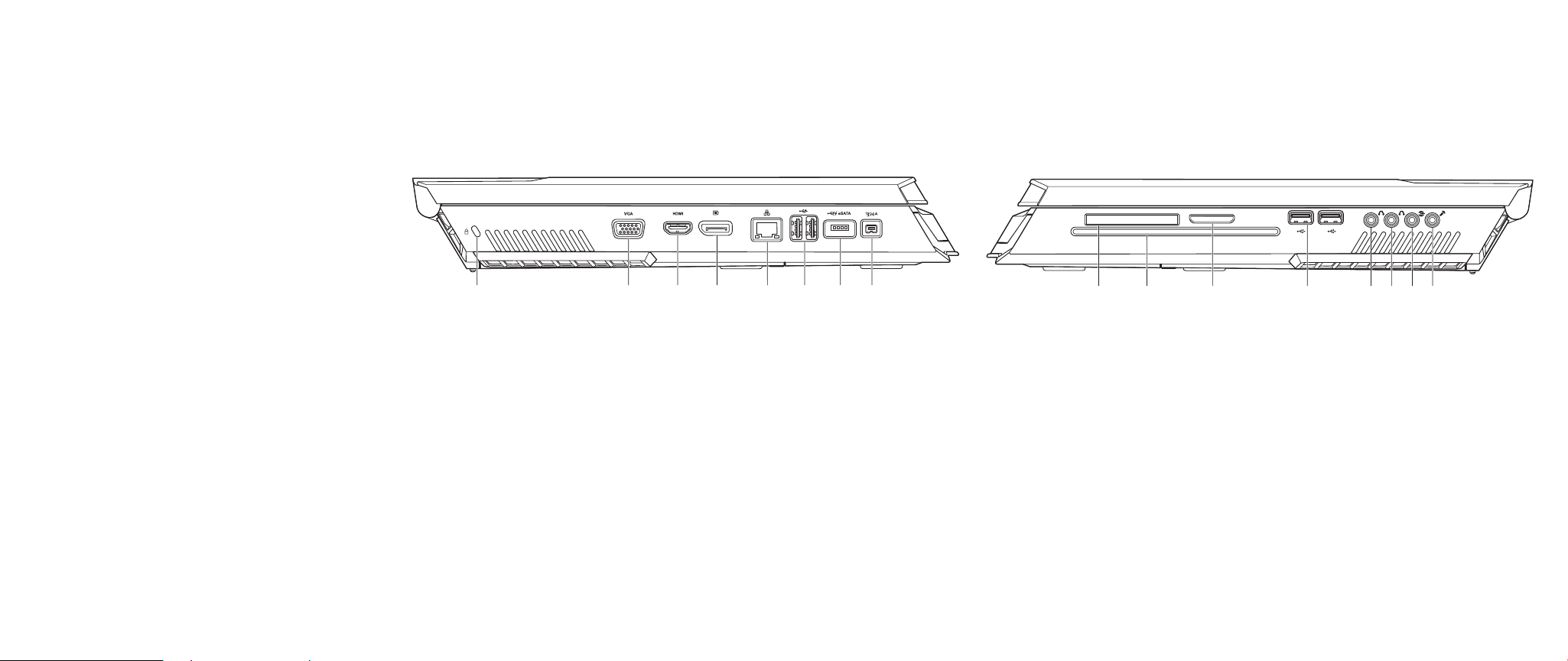
Left View Features
1
1 kensington lock 5 RJ45 LAN connector
2 VGA connector 6 USB connectors (2)
3 HDMI-Out connector 7 USB/eSATA combo connector with
4 DisplayPort connector 8 IEEE 1394A connector
2
3
4
USB PowerShare feature
5 6
7
8
Right View Features
1 2 3 4 5 86 7
1 ExpressCard slot 5 front speakers (left and right)
Audio Out connector/headphone
jack (Green)
2 optical drive 6 center speaker and subwoofer
Audio Out connector/headphone
jack (Orange)
3 media card slot 7 rear surround (left and right)
Audio Out connector (Black)
4 USB connectors (2) 8 Audio In connector/microphone
jack
012
/
012
CHAPTER 2: GETTING TO KNOW YOUR NOTEBOOK
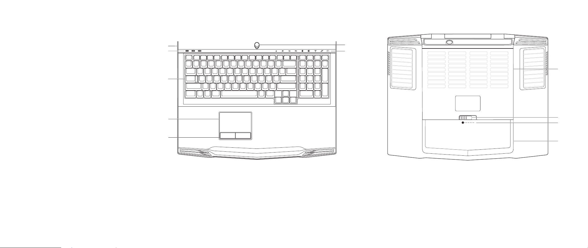
Top View Features
7
6
5
4
3
1 power button 5 keyboard
2 touch controls (9) 6 status LEDs (3)
3 touch pad buttons on rocker (2) 7 hinge cover
4 touch pad
Bottom View Features
1
2
1
2
3
4
1 compartment door 3 battery meter
2 battery latch 4 battery pack
013
/
013

CHAPTER 2: GETTING TO KNOW YOUR NOTEBOOK
Status LEDs
e three status LEDs are located at the top-left side of the keyboard. For the exact
location, please refer to the “Top View Features” diagram on page 13.
Scroll Lock LED
e LED lights up when the scroll lock option is switched on.
Caps Lock LED
e LED lights up when the keyboard is in Caps Lock mode. In this
mode, all characters you type are in uppercase.
Number Lock LED
e LED lights up when the keyboard is in Num Lock mode. In this
mode, the embedded numeric keypads can be used.
Power Button
is button is programmable by the user. For details on how to program this button,
please refer to Power Options in the Control Panel of Microsoft Windows operating
system.
e Power Button is located in the center of the hinge cover. For the exact location,
please refer to the “Top View Features” diagram on page 13.
e color of the AlienHead rim indicates the power status. e color indicating the
power status can be changed through the AlienFX® software.
On AC adapter:
Blue or custom AC-color e battery is fully charged.
Blue or custom AC-color fading
into Amber or custom batterycolor
Blue or custom AC-color fading
into Black
On battery:
Amber or custom battery-color e battery is fully charged.
Amber or custom battery-color
fading into Black
Blinking Amber or custom
battery-color
e notebook is powered o or on
and the battery is being charged.
e notebook is in sleep mode.
e notebook is in sleep mode.
e battery charge is low.
NOTE: Custom AC-color or Custom battery-colors are assigned by the user
when on AC-Mode or Battery-Mode.
For more details on Standby and Hibernate, please refer to Power Options in the
Control Panel of your Microsoft Windows operating system.
014
/
014
CHAPTER 2: GETTING TO KNOW YOUR NOTEBOOK
Touch Controls
e touch controls are located near the top of the keyboard. For the exact location,
refer to the “Top View Features” diagram on page 13. To activate, gently touch the
desired control. e control will illuminate temporarily to conrm your selection.
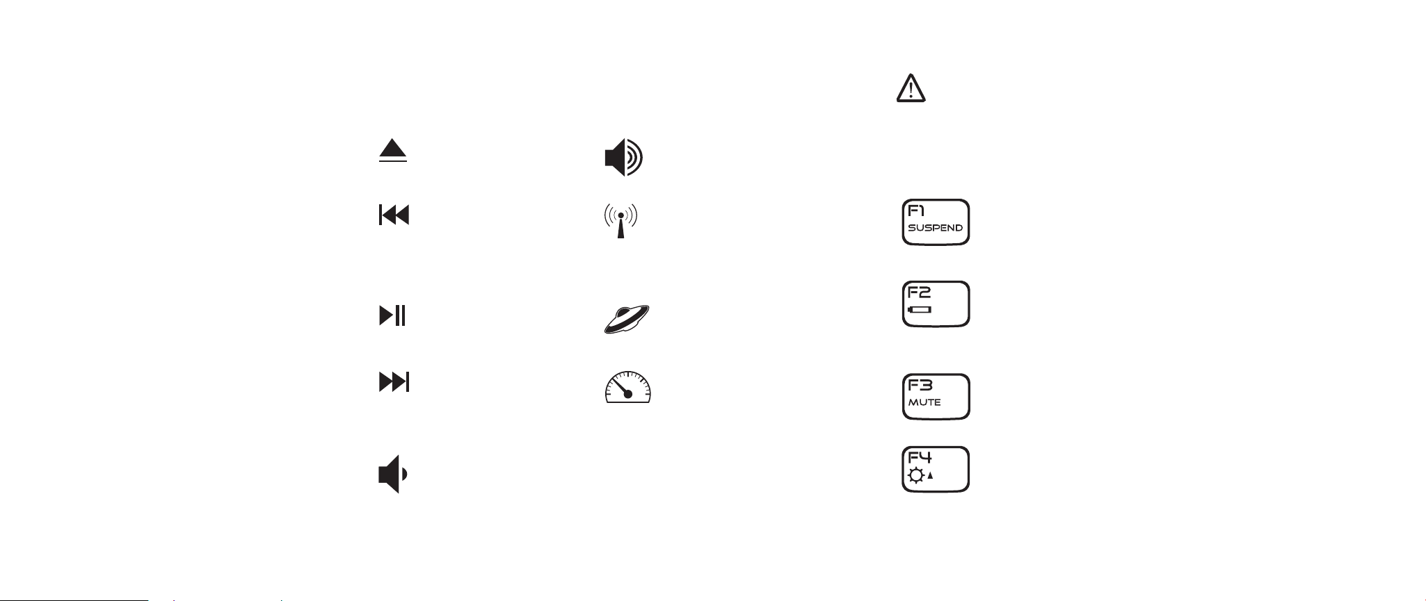
Eject Increase volume
Rewind/Play previous
track
Play/Pause Alienware Command Center
Fast Forward/Play next
track
Decrease volume
Wireless Control - Switch
wireless communications
on/o
(for details, refer to “Using the
Wireless Control” on page 25)
(for details, refer to “Alienware
Command Center” on page 24)
Stealth Mode - Switch
computer to low power state
(for details, refer to “Stealth
Mode” on page 25)
Function Keys
NOTE: Depending on the conguration of the notebook you have purchased,
some of the function keys may have no function.
e <Fn> key is located near the bottom-left corner of the keyboard. is key is
used together with other keys to activate certain pre-dened functions. To activate
these functions, press and hold down the <Fn> key along with the key described
below:
FI – Suspend Mode
Press <Fn><F1> to enter suspend mode. In suspend mode, the
LCD display and selected devices will be switched o for less
energy consumption.
F2 – Check Battery Status and Battery Charge Disable/
Enable
Press <Fn><F2> to toggle between the Battery Status Meter,
Battery Charge Disable feature, and Battery Charge Enable
feature.
F3 – Mute on/o
Press <Fn><F3> to enable or disable the mute function for the
audio.
F4 – Increase Display Brightness
Press <Fn><F4> to increase the brightness of the LCD display.
015
/
015
CHAPTER 2: GETTING TO KNOW YOUR NOTEBOOK
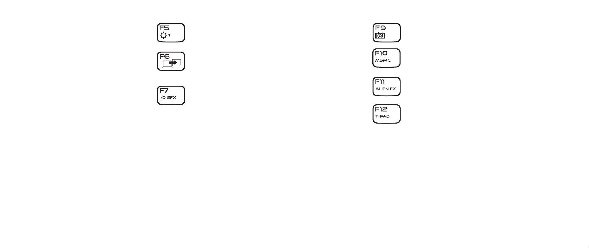
F5 – Decrease Display Brightness
Press <Fn><F5> to decrease the brightness of the LCD display.
F6 – Extend Desktop
Press <Fn><F6> to switch between the various external display
options available either simultaneously or separately.
F7 – Toggle between Integrated/Discrete Graphics
Press <Fn><F7> to switch between
integrated graphics and discrete graphics.
Integrated/binary graphics can be used to reduce your notebook’s
power consumption and extend your battery life, when the high
graphics performance of your discrete GPU(s) is not required.
Discrete graphics can be used when maximum performance is
required.
Switching between integrated/binary graphics and discrete
graphics may require a reboot depending on your system
conguration and the operating system. When in integrated/
binary graphics mode, your discrete graphics card(s), and their
cooling fans are turned o to save power. e use of external display
devices is not supported in the integrated/binary graphics mode.
F9 – Webcam on/o
Press <Fn><F9> to switch o or switch on the webcam module.
F10 – Microsoft Mobility Center on/o
Press <Fn><F10> to launch or close the Microsoft Mobility
Center application.
F11 – AlienFX® on/o
Press <Fn><F11> to disable or enable the AlienFX illumination.
F12 –Touch Pad on/o
Press <Fn><F12> to switch o or to switch on the touch pad
function and the illumination around the touch pad. When the
touch pad function is switched o, the touch pad can still work
temporarily for three to ve seconds while the system reboots
into the Windows® operating system, or resumes from standby
or hibernation.
016
/
016
Battery Pack
Your notebook is equipped with a high-energy rechargeable lithium ion (Li-ion)
battery pack. Battery life will vary depending on the notebook conguration,
notebook model, applications installed, power management settings of the
notebook, and notebook features used by the customer. As with all batteries, the
maximum capacity of this battery will decrease with time and usage.
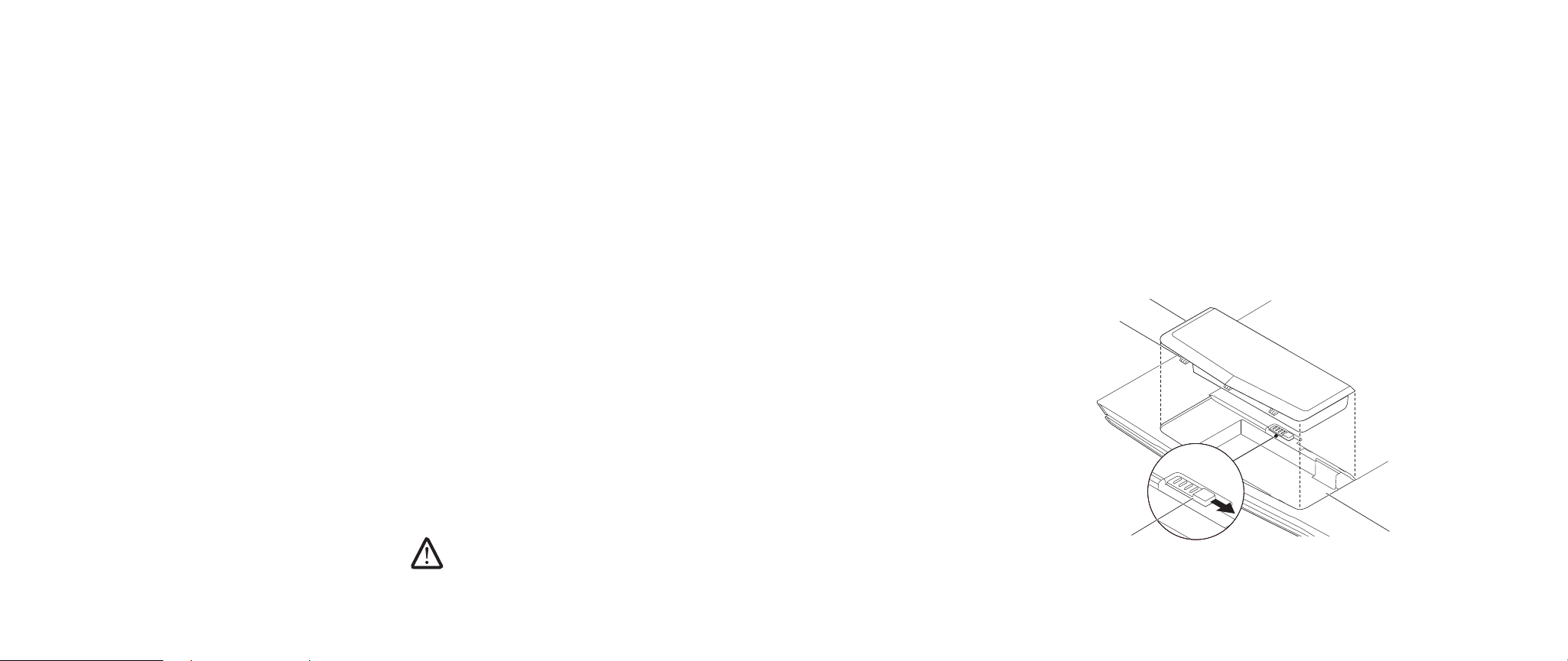
e battery meter LEDs on the battery pack indicates the charge level of the battery.
When you press the battery meter once, the charge level LEDs illuminate. Each of
5 LED represents approximately 20% of the total battery charge. For example, if
4 LEDs light up, there is 80% of battery charge remaining and if no LEDs light up,
there is no charge remaining in the battery.
CHAPTER 2: GETTING TO KNOW YOUR NOTEBOOK
Follow the steps below to remove the battery pack.
Shut down the notebook.1.
Flip the notebook upside down.2.
Push the battery latch to the unlock position as shown.3.
e battery pack will pop up.4.
Remove the battery pack.5.
Follow the steps below to replace the battery pack.
Align the three battery pack tabs with the battery bay.1.
Slide the battery pack into the battery bay until the battery pack clicks 2.
into place.
Recharging the Battery Pack
Your notebook supports both on-line and o-line recharge. Follow the procedure
below to recharge battery:
Make sure the battery pack is installed in the notebook.•
Connect the AC adapter to the notebook and to an electrical outlet.•
e power button LED is available to reect the power and battery status. For
details on the power button LED, refer to “Power Button” on page 14. When the
notebook is OFF, a depleted Li-ion battery will take three hours to recharge.
Removing and Replacing the Battery Pack
is battery pack can easily be removed and replaced. Make sure that the notebook
is properly shut down before changing the battery pack.
CAUTION: To avoid damage to the notebook, use only the battery designed
for this particular Alienware notebook. Do not use batteries designed for
other Alienware or Dell computers.
4
3
2
1
1 battery bay 3 battery pack tabs (3)
2 battery latch 4 battery pack
017
/
017

Battery Maintenance
To maintain the battery pack’s maximum capacity, you should occasionally let the
notebook deplete its battery power completely before recharging.
To carry out a complete depletion of the battery, disconnect the AC adapter and let
your notebook consume the remaining battery power. To speed up the depletion,
use the hard drive as much as possible and set the LCD as bright as possible. When
the battery is depleted or fully discharged, wait for the notebook to cool down
(especially the battery). e temperature should be within 15°-25°C (59°-77°F).
en connect the AC adapter to recharge the battery.
Questions and Answers
Q: I can feel a mild heat next to the battery pack. Is this normal?
A: e battery will generate heat during recharging and discharging. ere is a
protection circuit inside the notebook to prevent overheating. You do not need to
worry.
Q: My battery operation time is not as long as it should be. Why?
A: e battery is heat sensitive and can only be charged to its maximum if the
battery and its environmental temperature remain within 15°-25°C (59°-77°F). e
more the temperature deviates from this range during recharging, the less chance
there is for the battery to be fully charged. In order to recharge the pack to its full
capacity, users are requested to cool down the unit by unplugging the AC adapter.
Wait until it is cooled down. en plug in the AC adapter to start recharging again.
CHAPTER 2: GETTING TO KNOW YOUR NOTEBOOK
Q: I did not use my spare battery for a few days. Even though it was fully
recharged, there wasn’t as much power left as a newly charged one. Why?
A: e batteries will self-discharge (1% per day for Li-ion) when they are not being
recharged. To make sure a battery pack is fully charged, recharge before use.
Always keep the battery inside the notebook and have the AC adapter connected
whenever possible.
Q: I did not use my spare battery for months. I am having a problem
recharging it.
A: If you happen to leave your battery pack to go through an extended period of selfdischarge, say more than three months, the battery voltage level will become too
low and needs to be Pre-Charged (to bring the battery voltage level high enough)
before it automatically (for Li-ion only) resumes its normal Fast Charge. Pre-Charge
may take 30 minutes. Fast Charge usually takes 2-3 hours.
018
/
018

CHAPTER 2: GETTING TO KNOW YOUR NOTEBOOK
Power Management
Understanding Power Consumption
In order to fully utilize the power of your battery packs, it would be a good idea for
you to spend some time acquiring a basic understanding of the power management
concept from your operating system.
In Windows® operating systems, you can go through Power Options of the Control
Panel according to the version of the Windows® operating system the notebook
uses. Power options in Windows Vista® include three preferred power plans to
choose from:
Balanced•
Power Saver•
High Performance•
Customizing Your Notebook’s Power Settings:
Click 1. Start (Windows Vista® logo) > Control Panel.
Click 2. Classic View from the task panel.
Double-click the 3. Power Options icon.
Select a power plan from the options show. To customize specic settings, 4.
click Change plan settings beneath the selected power plan.
Reducing Power Consumption
Although your notebook (together with the operating system) is capable of power
conservation, there are measures you can take to reduce the power consumption:
Use the AC power whenever possible.•
Lower the intensity of the LCD backlight. A very bright screen translates to •
higher power usage.
Use <Fn><F7> to switch from discrete graphics mode to integrated graphics •
mode. You may have to reboot your computer to switch modes. For more
details see “Hybrid Graphics and Integrated Graphics Behaviors” on page 30.
Switch to the Stealth mode to switch from discrete to integrated/binary •
graphics mode and to activate additional system power savings to extend
battery life and to reduce power consumption. Switching into and out of
Stealth mode may require a reboot depending on your system conguration
and the operating system.
NOTE: e battery pack should be locked in the battery compartment all
the time.
019
/
019

CHAPTER 3: CONNECTING DEVICES
CHAPTER 3: CONNECTING DEVICES
CHAPTER 3: CONNECTING DEVICES
is section provides information about connecting optional devices to your
notebook to enhance your audio, visual, and digital experience.
020
/
020

CHAPTER 3: CONNECTING DEVICES
Connecting External Displays
If you want to enjoy your computing environment on a bigger scale visually, or
extend your desktop area, you can connect an external display such as a standalone
monitor, an LCD TV, or a projector.
NOTE: e external display connections in your Alienware notebook are
connected to your discrete graphics card(s). When you want to use an
external display device, turn o the integrated graphics (<Fn><F7>). is
will active the discrete graphics in your computer, and enable the external
display interfaces.
Connecting a Display
For the best picture quality, use the DisplayPort or HDMI connector on your digital
display. If your display does not have a DisplayPort or HDMI connector, you can
connect to the display using either a VGA cable from the notebook’s 15-pin VGA
connector or a DVI cable via a DisplayPort-to-DVI adapter. is adapter can be
purchased through Alienware, Dell, or other electronics retailers.
Turn o your notebook.1.
Turn o the digital display and unplug it from the power supply.2.
Connect one end of the display cable to the DisplayPort, HDMI, or VGA 3.
connector on your Alienware notebook.
Connect the other end of the cable to the same connector on your display.4.
If you are using a DisplayPort-to-DVI adapter, rst connect this adapter to 5.
the DisplayPort connector on your Alienware notebook and then connect a
DVI cable to the DVI connector on the adapter and tighten the thumb screws.
Connect the other end of the DVI cable to the DVI connector on your display.
If necessary, connect one end of the power cord to the display’s power 6.
connector.
Connect the other end of the power cord to a grounded three-prong power 7.
strip or wall outlet.
Turn on your notebook, and then turn on your display.8.
Extending the Desktop
With the external display connected, right-click on the desktop and select 1.
Personalize.
Select 2. Connect to a projector or other external display in the upper left
portion of the screen.
Click 3. Connect Display.
Select from the below options that appear on the screen:4.
Duplicate my display on all displays (mirrored)•
Show dierent parts of my desktop on each display (extended)•
Show my desktop on the external display only•
Click 5. Apply to apply your changes and then click OK to exit the Display
Settings control panel.
NOTE: When using NVIDIA Graphics with SLI enabled, only a single display
may be active at a time.
021
/
021

Connecting External Speakers
Your Alienware notebook has three integrated audio out connectors and one
audio in connector. e audio out connectors deliver quality sound and support
5.1 surround audio. You can connect the audio input connector from a home stereo
or speaker system for a heightened gaming and media experience.
Two types of audio connectors:
1
CHAPTER 3: CONNECTING DEVICES
2
1
2
1 front speakers (left and right)
Audio Out connector/headphone
jack (Green)
2 center speaker and subwoofer
Audio Out connector/headphone
jack (Orange)
3 4
3 rear surround (left and right)
Audio Out connector (Black)
4 Audio In connector/
microphone jack
1 stereo jack - Your headpone
jack should have this type of
connector
2 mono jack - Your microphone
should have this type of
connector
022
/
022

CHAPTER 3: CONNECTING DEVICES
Connecting Printers
Connecting a Plug and Play Printer
If your printer supports plug and play, Windows Vista will detect it and attempt
to install the printer automatically. In some cases, Windows may require a driver
for the printer. is driver is located on the software CD that is included with the
printer.
Connect the printer’s USB cable to an available USB connector, located at the 1.
sides of the notebook.
Connect the printer’s power cord to a grounded, three-prong power-strip, 2.
uninterruptible power supply, or wall outlet.
Turn on the printer and Windows Vista will automatically detect it and install 3.
the appropriate driver.
Connecting a Non Plug and Play Printer
Click the 1. Start button (Windows logo).
Click 2. Control Panel.
Click 3. Hardware and Sound.
Click 4. Add a printer and follow the instructions on the screen.
For further information, please refer to your printer’s documentation.
Connecting USB Devices
Plug the USB device into an available USB connector on your notebook. Windows
Vista will detect the device and attempt to install the appropriate driver
automatically. In some cases, Windows may require a driver. is driver is located
on the software CD that is included with the device.
If your keyboard or mouse uses a USB connection, insert its USB connector into an
available USB connector on the notebook. For further information, please refer to
your device’s documentation.
e USB/eSATA combo connector with USB PowerShare feature can connect to
eSATA compatible devices and USB devices. is connector can also be used for
charging USB devices when the computer is on/o or in sleep state.
e USB PowerShare feature is enabled in the BIOS setup by default. When the
notebook is on battery mode, you can disable the feature through the Advanced
Menu in BIOS (for details, refer to “Entering System Setup” on page 27).
NOTE: e USB PowerShare will be automatically shut o when only 10% of
total battery life remains.
Connecting FireWire (IEEE 1394) Devices
Plug the FireWire device into the FireWire connector on your notebook. Windows
Vista will detect the device and attempt to install the appropriate driver
automatically. In some cases, Windows may require a driver. is driver is located
on the software CD that is included with the device.
For further information, please refer to your device’s documentation.
023
/
023

CHAPTER 4: USING YOUR NOTEBOOK
CHAPTER 4: USING YOUR NOTEBOOK
CHAPTER 4: USING YOUR NOTEBOOK
Alienware Command Center
e Alienware® Command Center gives you access to Alienware’s exclusive
software and is a continuously upgradable control panel. As Alienware releases
new programs, they download directly into the Command Center allowing you to
build a library of system management, optimization, and customization tools.
You can access Alienware Command Center by gently touching the touch control
located near the top of the keyboard. e control will illuminate temporarily to
conrm your selection. For the exact location of the control, refer to the “Top View
Features” diagram on page 13.
024
/
024

CHAPTER 4: USING YOUR NOTEBOOK
Stealth Mode
Stealth Mode helps you switch your notebook to a low power state to facilitate the
use of a 65 W auto/air adapter. is state is well suited for casual use such as e-mail,
music/video/DVD playback. Stealth mode will switch the notebook from discrete to
integrated graphics mode, and also incorporate additional system power savings
to extend battery life and reduce power consumption. Switching into and out of
Stealth mode may require a reboot depending on your system conguration and
the operating system.
You can access Stealth Mode by gently touching the touch control located near the
top of the keyboard. e control will illuminate to full brightness until the function
is deactivated. For the exact location of the control, refer to the “Top View Features”
diagram on page 13.
Using Removable Media and Cards
Please observe the safety measures below:
When the ExpressCard is not inserted into the ExpressCard slot, make sure this
slot is covered by the spring-loaded slot door attached to your notebook. e
ExpressCard slot door protects the unused slot from dust and other particles.
When no card (SD/MMC/MS Cards) is inserted into the media slot, make sure that
the blank card that shipped with your notebook is inserted in this slot. e blank
card protects the unused slot from dust and other particles. When inserting the
blank card, make sure that the arrow on the card is on the top. Inserting the blank
card upside down may cause damage to your notebook.
DVD±R/W Dual
Layer Writer
Blu-ray Disc
Reader/Writer
A DVD±R/W drive can read CD-ROM, CD-R, CD-R/W,
DVD, DVD+R/W and DVD-R/W media.
It can also record to CD-R, CD-RW, DVD+R/W and DVDR/W and DVD+R Dual Layer (DL) media.
A Blu-ray drive can read CD-ROM, CD-R, CD-R/W, DVD,
DVD+R/W, DVD-R/W, DVD+R Dual Layer (DL), BD-ROM,
BD-R, and BD-RE media.
It can also record to CD-R, CD-R/W, DVD+R/W, DVDR/W, DVD+R Dual Layer (DL), BD-R, and BD-RE media.
Using the Integrated Webcam
Turning the Webcam On and O
Press the key combination <Fn><F9> to switch on or switch o the webcam
module. After switching on the webcam, you need to activate its function through
the Microsoft Windows operating system. In addition, you can also use Windows
Movie Maker to create, edit, and share videos.
Using the Wireless Control
Using the Optical Drive
Your notebook has a slot load optical drive. Depending on the conguration
ordered, your notebook is congured with one or more of the following drive types.
ese logos are used to indicate each drive’s respective capabilities and media
compatibility.
e wireless control allows you to quickly turn all of your wireless radios (Bluetooth®
and WLAN) o, such as when you are asked to disable all wireless radios on an
airplane ight. Gently touching this control one time turns all of your radios o.
Gently touching it again returns your wireless radios to their respective states they
were in before you touched the control the rst time.
025
/
025
Working With RAID
A redundant array of independent disks (RAID) is a disk storage conguration
that increases performance or data redundancy. ere are two basic RAID levels
discussed in this section.
RAID level 0 is recommended for higher performance (faster throughput). •
RAID level 1 is recommended for users who need a high level of data integrity.•
NOTE: RAID requires multiple hard drives. e number of hard drives
required varies depending on the RAID conguration.
RAID Level 0
CAUTION: RAID level 0 provides no redundancy. erefore, a failure of one
drive results in the loss of all data. Perform regular backups to protect
your data.
RAID level 0 uses data striping to provide a high data access rate. Data striping
writes consecutive segments, or stripes, of data sequentially across the physical
drive(s) to create a large virtual drive. is allows one of the drives to read data
while the other drive is searching for and reading the next block.
CHAPTER 4: USING YOUR NOTEBOOK
RAID 0 uses the full storage capacities of both drives. For example, two 2 GB hard
drives combine to provide 4 GB of hard drive space on which to store data.
NOTE: In a RAID 0 conguration, the size of the conguration is equal to
size of the smallest drive multiplied by the number of drives in the
conguration.
the
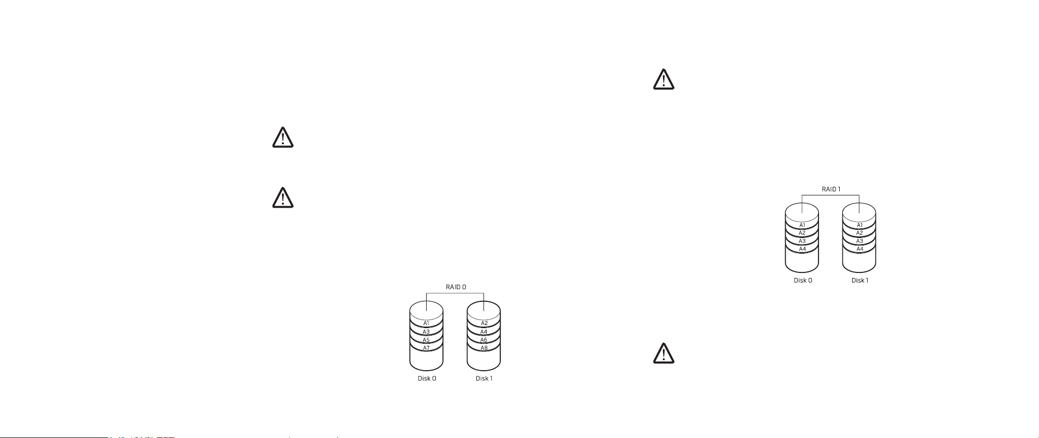
RAID Level 1
RAID level 1 uses data mirroring to enhance data integrity. When data is written to
the primary drive, the data is also duplicated, or mirrored, on the secondary drive in
the conguration. RAID 1 sacrices high data-access rates for data redundancy.
If a drive failure occurs, read and write operations are directed to the remaining
drive. A replacement drive can then be rebuilt using the data from the remaining
drive.
NOTE: In a RAID 1 conguration, the size of the conguration is equal to the
size of the smallest drive in the conguration.
026
/
026

CHAPTER 4: USING YOUR NOTEBOOK
Conguring the BIOS
System Setup
e System Setup options allow you to:
Change the system conguration information after you add, change, or •
remove any hardware in your notebook.
Set or change a user-selectable option.•
Read the current amount of memory or set the type of hard drive installed.•
Before you use System Setup, it is recommended that you write down the current
System Setup information for future reference.
CAUTION: Do not change the settings in System Setup unless you are an
expert computer user. Certain changes can cause your computer to work
incorrectly.
Entering System Setup
Turn on (or restart) your notebook.1.
While the notebook is booting, press <F2> immediately to access the BIOS 2.
Setup Utility.
If an error occurs during POST (Power On Self Test), you may also enter the
BIOS Setup Utility by pressing <F2> when prompted.
NOTE: If you wait too long and the operating system logo appears, continue
to wait until you see the Microsoft® Windows® desktop, then shut down your
notebook and try again.
NOTE: Keyboard failure may result when a key on the keyboard is held down
for extended periods of time. To avoid possible keyboard failure, press and
release <F2> in even intervals until the System Setup screen appears.
System Setup Screens
e BIOS Setup Utility window displays current or changeable conguration
information for your notebook. Information is divided into ve menus: Main,
Advanced, Security, Boot, and Exit.
Key functions appear at the bottom of the Setup Utility screen and lists keys and
their functions within the active eld.
027
/
027

CHAPTER 4: USING YOUR NOTEBOOK
System Setup Options
NOTE: Depending on your computer and installed devices, the items listed
in this section may not appear, or may not appear exactly as listed.
Main Menu
System Time Displays the system time.
System Date Displays the system date.
BIOS Version Displays the BIOS revision.
Product Name Displays the model number of the system.
CPU Type Displays the type of processor.
CPU Speed Displays the speed of the processor.
CPU Cache Size Displays the processor cache size.
CPU ID Displays the ID of the processor.
SATA ODD Displays the conguration of the SATA compatible optical
drive.
Fixed HDD1 Displays the conguration of the primary hard drive.
Fixed HDD2 Displays the conguration of the secondary hard drive.
System Memory Displays the memory available in the system.
Extended Memory Displays the total memory size.
AC Adapter Type Displays the type of AC adapter.
Memory Speed Displays the memory speed.
Advanced Menu
Summary Screen Allows you to enable or disable the diagnostic
screen during boot.
QuickBoot Mode Allows you to enable or disable the quick boot
mode by which the system can skip certain tests
while booting. is option will decrease the time
needed to boot the system.
®
Virtualization
Intel
Technology
Allows you to enable or disable the virtualization
technology. is option species whether a
Virtual Machine Monitor (VMM) can utilize the
additional hardware capabilities provided by Intel
Virtualization Technology.
Integrated NIC Allows you to enable or disable the on-board LAN
controller.
Disabled: Internal LAN is o and is not visible •
to the operating system.
Enabled: Internal LAN is enabled. •
Internal Bluetooth Allows you to enable or disable the internal
Bluetooth device.
Disabled: e internal Bluetooth device is o •
and is not visible to the operating system.
Enabled: e internal Bluetooth device is •
enabled.
SATA Operation Allows you to congure the operating mode of the
integrated SATA hard drive controller.
ATA: SATA is congured for ATA mode.•
AHCI: SATA is congured for AHCI mode.•
RAID: SATA is congured for RAID mode.•
028
/
028
 Loading...