

Page 1

Alienware m17 R3
Service Manual
Regulatory Model: P45E
Regulatory Type: P45E001
Page 2

Notes, cautions, and warnings
NOTE: A NOTE indicates important information that helps you make better use of your product.
CAUTION: A CAUTION indicates either potential damage to hardware or loss of data and tells you how to avoid the
problem.
WARNING: A WARNING indicates a potential for property damage, personal injury, or death.
© 2020 Dell Inc. or its subsidiaries. All rights reserved. Dell, EMC, and other trademarks are trademarks of Dell Inc. or its
subsidiaries. Other trademarks may be trademarks of their respective owners.
2020 - 03
Rev. A00
Page 3

Contents
1 Working inside your computer..............................................................................................................6
Before working inside your computer.................................................................................................................................6
Safety instructions.................................................................................................................................................................6
Electrostatic discharge—ESD protection............................................................................................................................7
ESD field service kit .............................................................................................................................................................7
Transporting sensitive components......................................................................................................................................8
After working inside your computer....................................................................................................................................8
2 Removing and installing components................................................................................................... 9
Recommended tools.............................................................................................................................................................9
Screw list............................................................................................................................................................................... 9
Base cover........................................................................................................................................................................... 10
Removing the base cover..............................................................................................................................................10
Installing the base cover................................................................................................................................................12
Solid state drive—M.2 slot one..........................................................................................................................................14
Removing the 2280 solid-state drive from the M.2 slot one...................................................................................... 14
Installing the 2280 solid-state drive from the M.2 slot one........................................................................................15
Removing the 2230 solid-state drive from the M.2 slot one...................................................................................... 16
Installing the M.2 2230 solid-state drive from the M.2 slot one.................................................................................17
Solid state drive—M.2 slot two..........................................................................................................................................19
Removing the 2280 solid-state drive from the M.2 slot two......................................................................................19
Installing the 2280 solid-state drive from the M.2 slot two........................................................................................19
Removing the 2230 solid-state drive from the M.2 slot two..................................................................................... 20
Installing the 2230 solid-state drive from the M.2 slot two....................................................................................... 22
Solid state drive—M.2 slot three....................................................................................................................................... 23
Removing the 2230 solid-state drive from the M.2 slot three................................................................................... 23
Installing the 2230 solid-state drive from the M.2 slot three.....................................................................................24
Battery................................................................................................................................................................................ 25
Lithium-ion battery precautions...................................................................................................................................25
Removing the battery...................................................................................................................................................25
Installing the battery.....................................................................................................................................................26
Speakers..............................................................................................................................................................................27
Removing the speakers................................................................................................................................................. 27
Installing the speakers...................................................................................................................................................28
Keyboard-controller board............................................................................................................................................... 29
Removing the keyboard-controller board...................................................................................................................29
Installing the keyboard-controller board.................................................................................................................... 30
Touchpad.............................................................................................................................................................................31
Removing the touchpad................................................................................................................................................31
Installing the touchpad................................................................................................................................................. 32
Rear-I/O cover...................................................................................................................................................................34
Removing the rear I/O-cover...................................................................................................................................... 34
Installing the rear I/O-cover........................................................................................................................................ 35
3
Page 4

Display assembly.................................................................................................................................................................37
Removing the display assembly.................................................................................................................................... 37
Installing the display assembly..................................................................................................................................... 40
Right I/O-board................................................................................................................................................................ 42
Removing the right I/O-board.................................................................................................................................... 42
Installing the right I/O-board...................................................................................................................................... 43
System board......................................................................................................................................................................45
Removing the system board......................................................................................................................................... 45
Installing the system board........................................................................................................................................... 47
Left I/O-board.................................................................................................................................................................. 49
Removing the left I/O-board...................................................................................................................................... 49
Installing the left I/O-board........................................................................................................................................50
Fan and heat-sink assembly................................................................................................................................................51
Removing the fan and heat-sink assembly................................................................................................................... 51
Installing the fan and heat-sink assembly.................................................................................................................... 53
Power-adapter port...........................................................................................................................................................54
Removing the power-adapter port..............................................................................................................................54
Installing the power-adapter port............................................................................................................................... 55
Power-button assembly..................................................................................................................................................... 56
Removing the power-button assembly........................................................................................................................56
Installing the power-button assembly..........................................................................................................................57
Keyboard............................................................................................................................................................................ 58
Removing the keyboard............................................................................................................................................... 58
Installing the keyboard.................................................................................................................................................60
Palmrest.............................................................................................................................................................................. 62
Removing the palm rest................................................................................................................................................ 62
Installing the palm rest.................................................................................................................................................. 63
3 Drivers and downloads........................................................................................................................65
4 System setup....................................................................................................................................... 66
Entering BIOS setup program........................................................................................................................................... 66
Navigation keys..................................................................................................................................................................66
One time boot menu..........................................................................................................................................................66
System setup options..........................................................................................................................................................67
Main............................................................................................................................................................................... 67
Advanced...................................................................................................................................................................... 67
Security..........................................................................................................................................................................69
Secure boot....................................................................................................................................................................71
Secure boot....................................................................................................................................................................71
Updating the BIOS in Windows ....................................................................................................................................... 72
Updating BIOS on systems with BitLocker enabled....................................................................................................73
Updating your system BIOS using a USB flash drive...................................................................................................73
Flashing the BIOS from the F12 One-Time boot menu.................................................................................................... 73
System and setup password............................................................................................................................................... 76
Assigning a system setup password.............................................................................................................................. 77
Deleting or changing an existing system setup password...........................................................................................77
Clearing CMOS settings............................................................................................................................................... 77
Clearing BIOS (System Setup) and System passwords................................................................................................78
4
Page 5

5 Troubleshooting...................................................................................................................................79
Recovering the operating system...................................................................................................................................... 79
System diagnostic lights..................................................................................................................................................... 79
Flea power release............................................................................................................................................................. 80
WiFi power cycle............................................................................................................................................................... 80
6 Getting help.........................................................................................................................................81
Contacting Dell...................................................................................................................................................................81
5
Page 6

Working inside your computer
Before working inside your computer
About this task
NOTE: The images in this document may differ from your computer depending on the configuration you ordered.
Steps
1. Save and close all open files and exit all open applications.
2. Shut down your computer. Click Start > Power > Shut down.
NOTE: If you are using a different operating system, see the documentation of your operating system for shut-down
instructions.
3. Disconnect your computer and all attached devices from their electrical outlets.
4. Disconnect all attached network devices and peripherals, such as keyboard, mouse, and monitor from your computer.
CAUTION: To disconnect a network cable, first unplug the cable from your computer and then unplug the cable from
the network device.
5. Remove any media card and optical disc from your computer, if applicable.
Safety instructions
Use the following safety guidelines to protect your computer from potential damage and to ensure your personal safety. Unless
otherwise noted, each procedure included in this document assumes that you have read the safety information that shipped with your
computer.
NOTE: Before working inside your computer, read the safety information that is shipped with your computer. For more
safety best practices, see the Regulatory Compliance home page at www.dell.com/regulatory_compliance.
NOTE: Disconnect your computer from all power sources before opening the computer cover or panels. After you finish
working inside the computer, replace all covers, panels, and screws before connecting your computer to an electrical outlet.
CAUTION: To avoid damaging the computer, ensure that the work surface is flat, dry and clean.
CAUTION: To avoid damaging the components and cards, handle them by their edges, and avoid touching the pins and the
contacts.
CAUTION: You should only perform troubleshooting and repairs as authorized or directed by the Dell technical assistance
team. Damage due to servicing that is not authorized by Dell is not covered by your warranty. See the safety instructions
that is shipped with the product or at www.dell.com/regulatory_compliance.
CAUTION: Before touching anything inside your computer, ground yourself by touching an unpainted metal surface, such
as the metal at the back of the computer. While you work, periodically touch an unpainted metal surface to dissipate static
electricity which could harm internal components.
CAUTION: When you disconnect a cable, pull it by its connector or its pull tab, not the cable itself. Some cables have
connectors with locking tabs or thumb-screws that you must disengage before disconnecting the cable. When
disconnecting cables, keep them evenly-aligned to avoid bending the connector pins. When connecting cables, ensure that
the ports and the connectors are correctly oriented and aligned.
CAUTION: Press and eject any installed card from the media-card reader.
NOTE: The color of your computer and certain components may appear differently than shown in this document.
6
Page 7

Electrostatic discharge—ESD protection
ESD is a major concern when you handle electronic components, especially sensitive components such as expansion cards, processors,
memory DIMMs, and system boards. Very slight charges can damage circuits in ways that may not be obvious, such as intermittent
problems or a shortened product life span. As the industry pushes for lower power requirements and increased density, ESD
protection is an increasing concern.
Due to the increased density of semiconductors used in recent Dell products, the sensitivity to static damage is now higher than in
previous Dell products. For this reason, some previously approved methods of handling parts are no longer applicable.
Two recognized types of ESD damage are catastrophic and intermittent failures.
• Catastrophic – Catastrophic failures represent approximately 20 percent of ESD-related failures. The damage causes an
immediate and complete loss of device functionality. An example of catastrophic failure is a memory DIMM that has received a
static shock and immediately generates a "No POST/No Video" symptom with a beep code emitted for missing or nonfunctional
memory.
• Intermittent – Intermittent failures represent approximately 80 percent of ESD-related failures. The high rate of intermittent
failures means that most of the time when damage occurs, it is not immediately recognizable. The DIMM receives a static shock,
but the tracing is merely weakened and does not immediately produce outward symptoms related to the damage. The weakened
trace may take weeks or months to melt, and in the meantime may cause degradation of memory integrity, intermittent memory
errors, etc.
The more difficult type of damage to recognize and troubleshoot is the intermittent (also called latent or "walking wounded") failure.
Perform the following steps to prevent ESD damage:
• Use a wired ESD wrist strap that is properly grounded. The use of wireless anti-static straps is no longer allowed; they do not
provide adequate protection. Touching the chassis before handling parts does not ensure adequate ESD protection on parts with
increased sensitivity to ESD damage.
• Handle all static-sensitive components in a static-safe area. If possible, use anti-static floor pads and workbench pads.
• When unpacking a static-sensitive component from its shipping carton, do not remove the component from the anti-static
packing material until you are ready to install the component. Before unwrapping the anti-static packaging, ensure that you
discharge static electricity from your body.
• Before transporting a static-sensitive component, place it in an anti-static container or packaging.
ESD field service kit
The unmonitored Field Service kit is the most commonly used service kit. Each Field Service kit includes three main components: antistatic mat, wrist strap, and bonding wire.
Components of an ESD field service kit
The components of an ESD field service kit are:
• Anti-Static Mat – The anti-static mat is dissipative and parts can be placed on it during service procedures. When using an anti-
static mat, your wrist strap should be snug and the bonding wire should be connected to the mat and to any bare metal on the
system being worked on. Once deployed properly, service parts can be removed from the ESD bag and placed directly on the
mat. ESD-sensitive items are safe in your hand, on the ESD mat, in the system, or inside a bag.
• Wrist Strap and Bonding Wire – The wrist strap and bonding wire can be either directly connected between your wrist and bare
metal on the hardware if the ESD mat is not required, or connected to the anti-static mat to protect hardware that is temporarily
placed on the mat. The physical connection of the wrist strap and bonding wire between your skin, the ESD mat, and the
hardware is known as bonding. Use only Field Service kits with a wrist strap, mat, and bonding wire. Never use wireless wrist
straps. Always be aware that the internal wires of a wrist strap are prone to damage from normal wear and tear, and must be
checked regularly with a wrist strap tester in order to avoid accidental ESD hardware damage. It is recommended to test the wrist
strap and bonding wire at least once per week.
• ESD Wrist Strap Tester – The wires inside of an ESD strap are prone to damage over time. When using an unmonitored kit, it is a
best practice to regularly test the strap prior to each service call, and at a minimum, test once per week. A wrist strap tester is the
best method for doing this test. If you do not have your own wrist strap tester, check with your regional office to find out if they
have one. To perform the test, plug the wrist-strap's bonding-wire into the tester while it is strapped to your wrist and push the
button to test. A green LED is lit if the test is successful; a red LED is lit and an alarm sounds if the test fails.
• Insulator Elements – It is critical to keep ESD sensitive devices, such as plastic heat sink casings, away from internal parts that are
insulators and often highly charged.
• Working Environment – Before deploying the ESD Field Service kit, assess the situation at the customer location. For example,
deploying the kit for a server environment is different than for a desktop or portable environment. Servers are typically installed
in a rack within a data center; desktops or portables are typically placed on office desks or cubicles. Always look for a large open
flat work area that is free of clutter and large enough to deploy the ESD kit with additional space to accommodate the type of
7
Page 8

system that is being repaired. The workspace should also be free of insulators that can cause an ESD event. On the work area,
insulators such as Styrofoam and other plastics should always be moved at least 12 inches or 30 centimeters away from sensitive
parts before physically handling any hardware components
• ESD Packaging – All ESD-sensitive devices must be shipped and received in static-safe packaging. Metal, static-shielded bags
are preferred. However, you should always return the damaged part using the same ESD bag and packaging that the new part
arrived in. The ESD bag should be folded over and taped shut and all the same foam packing material should be used in the
original box that the new part arrived in. ESD-sensitive devices should be removed from packaging only at an ESD-protected
work surface, and parts should never be placed on top of the ESD bag because only the inside of the bag is shielded. Always
place parts in your hand, on the ESD mat, in the system, or inside an anti-static bag.
• Transporting Sensitive Components – When transporting ESD sensitive components such as replacement parts or parts to be
returned to Dell, it is critical to place these parts in anti-static bags for safe transport.
ESD protection summary
It is recommended that all field service technicians use the traditional wired ESD grounding wrist strap and protective anti-static mat
at all times when servicing Dell products. In addition, it is critical that technicians keep sensitive parts separate from all insulator parts
while performing service and that they use anti-static bags for transporting sensitive components.
Transporting sensitive components
When transporting ESD sensitive components such as replacement parts or parts to be returned to Dell, it is critical to place these
parts in anti-static bags for safe transport.
Lifting equipment
Adhere to the following guidelines when lifting heavy weight equipment:
CAUTION: Do not lift greater than 50 pounds. Always obtain additional resources or use a mechanical lifting device.
1. Get a firm balanced footing. Keep your feet apart for a stable base, and point your toes out.
2. Tighten stomach muscles. Abdominal muscles support your spine when you lift, offsetting the force of the load.
3. Lift with your legs, not your back.
4. Keep the load close. The closer it is to your spine, the less force it exerts on your back.
5. Keep your back upright, whether lifting or setting down the load. Do not add the weight of your body to the load. Avoid twisting
your body and back.
6. Follow the same techniques in reverse to set the load down.
After working inside your computer
About this task
CAUTION: Leaving stray or loose screws inside your computer may severely damage your computer.
Steps
1. Replace all screws and ensure that no stray screws remain inside your computer.
2. Connect any external devices, peripherals, or cables you removed before working on your computer.
3. Replace any media cards, discs, or any other parts that you removed before working on your computer.
4. Connect your computer and all attached devices to their electrical outlets.
5. Turn on your computer.
8
Page 9
Removing and installing components
Recommended tools
The procedures in this document may require the following tools:
• Philips screwdriver #1
• Philips screwdriver #00
• Plastic scribe
Screw list
NOTE: When removing screws from a component, it is recommended to note the screw type, the quantity of screws, and
then place them in a screw storage box. This is to ensure that the correct number of screws and correct screw type is
restored when the component is replaced.
NOTE: Some computers have magnetic surfaces. Ensure that the screws are not left attached to such surface when
replacing a component.
NOTE: Screw color may vary with the configuration ordered.
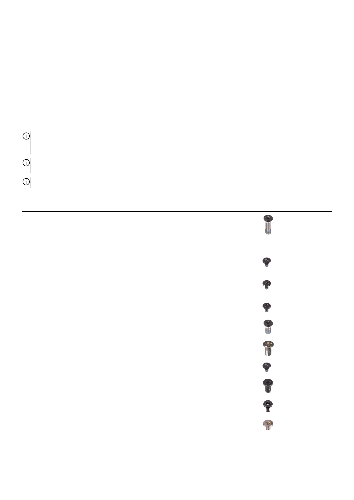
Table 1. Screw list
Component Secured to Screw type Quantity Screw image
Base cover Palm-rest assembly M2.5x9 2
M.2 2230 solid-state
drive in M.2 slot three
M.2 2230 solid-state
drive in M.2 slot one or
M.2 slot two
M.2 2230 mounting
bracket in M.2 slot one or
M.2 slot two
M.2 2280 solid-state
drive
Rear I/O-cover Palm-rest assembly M2.5x5 2
Rear I/O-cover Palm-rest assembly M2x4.5 2
Wireless-card bracket Left I/O-board M2x3 1
Display assembly Palm-rest assembly M2.5x5 6
Battery Palm-rest assembly M2x4 4
Palm-rest assembly M2x3 2
M.2 2230 mounting
bracket
Palm-rest assembly M2x3 1 per M.2 2230 solid-
Palm-rest assembly M2x3 1 per M.2 2280 solid-
M2x3 1 per M.2 2230 solid-
state drive
state drive
state drive
Battery Palm-rest assembly M2x3 3
9
Page 10
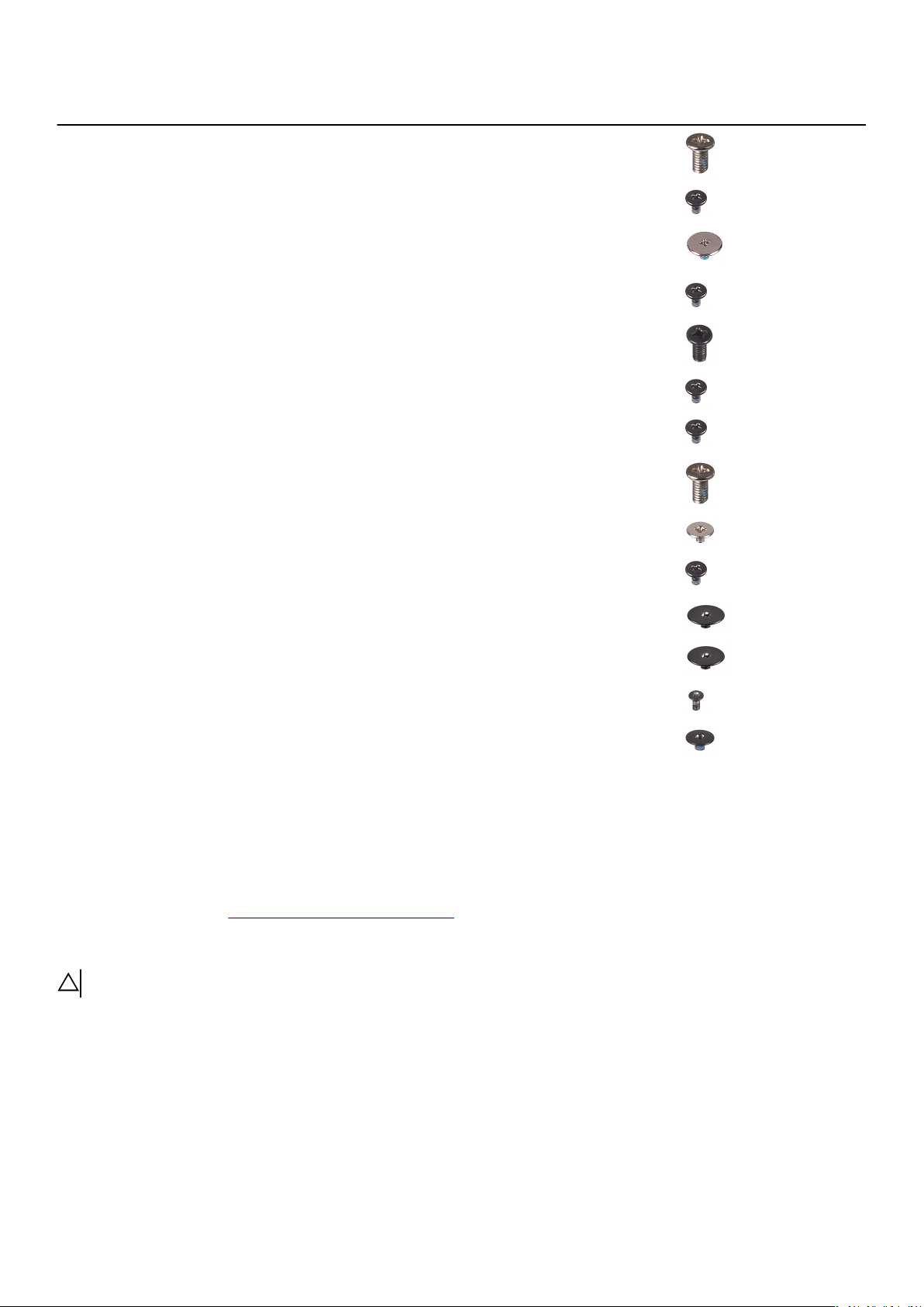
Component Secured to Screw type Quantity Screw image
Left I/O-board
connector
Left I/O-board Palm-rest assembly M2x3 3
• System board
• Left I/O-board
M2x4.5 4
Right I/O-board
connector
Right I/O-board Palm-rest assembly M2x3 3
Fans Palm-rest assembly M2.5x5 2
System board Palm-rest assembly M2x3 5
Fan and heat-sink
assembly
Solid-state drive support
bracket
Touchpad Palm-rest assembly M2x2.5 4
Power-adapter port
bracket
Power-button assembly Palm-rest assembly M2x1.9 2
Keyboard-controller
board
Keyboard bracket Keyboard M1.2x2.1 10
• System board
• Right I/O-board
System board M2x3 10
Palm-rest assembly M2x4.5 3
Palm-rest assembly M2x3 2
Palm-rest assembly M2x1.9 2
M2x3 2
Keyboard Palm-rest assembly M1.2x1.6 28
Base cover
Removing the base cover
Prerequisites
1. Follow the procedure in Before working inside your computer.
About this task
CAUTION: Ensure that all captive screws are loosened before prying up the base cover.
The following image indicates the location of the base cover and provides a visual representation of the removal procedure.
10
Page 11
11
Page 12
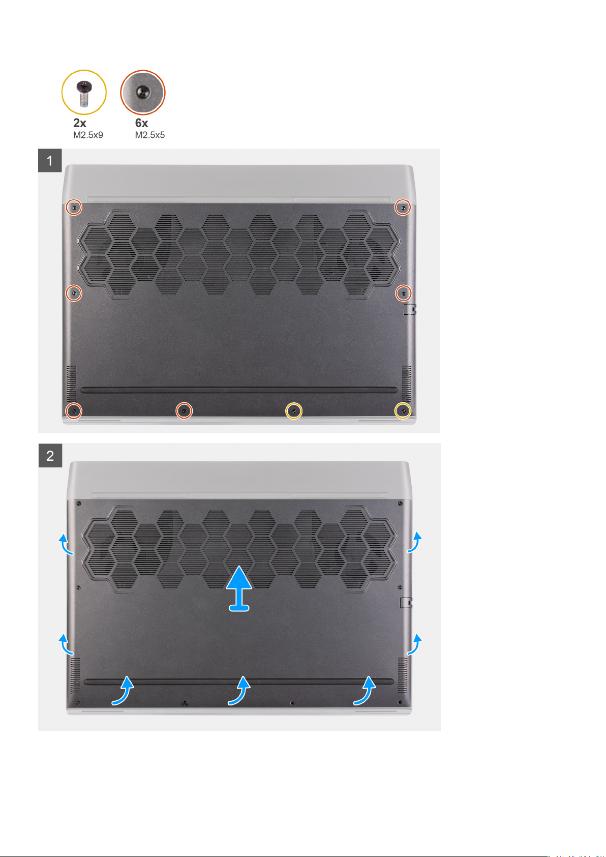
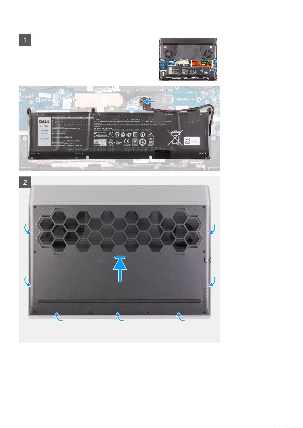
Steps
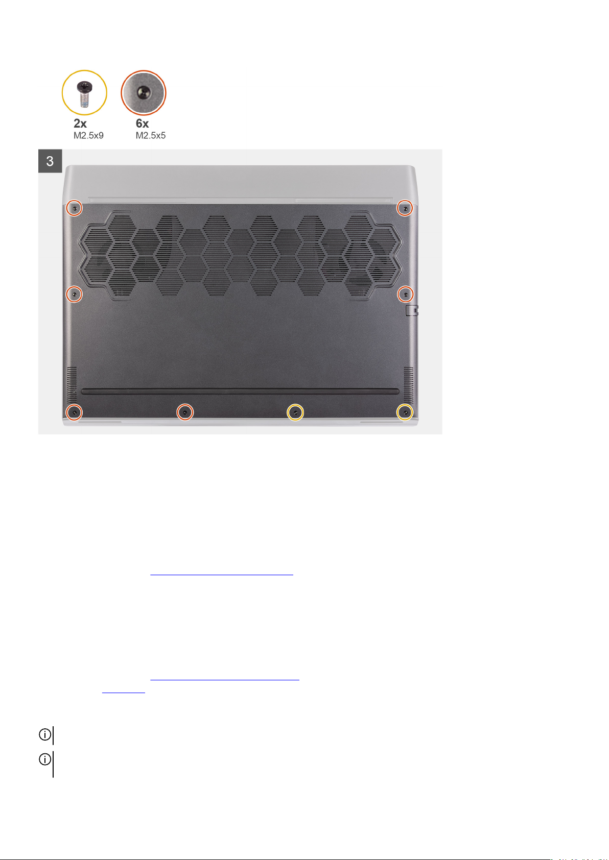
1. Remove the two screws (M2.5x9) that secure the base cover to the palm-rest assembly.
2. Loosen the six captive screws.
3. Using your fingertips, pry the base cover from the gap around the screw holes to release clips on the base cover from the palm-
rest assembly.
4. Work on the sides to pry open the base cover.
5. Lift the base cover off the palm-rest assembly.
6. Disconnect the battery from the system board.
NOTE: Disconnect the battery cable only when you are continuing to remove other components from your computer.
7. Press and hold the power button for 5 seconds to ground the computer and drain the flea power.
Installing the base cover
Prerequisites
If you are replacing a component, remove the existing component before performing the installation procedure.
About this task
The following image indicates the location of the base cover and provides a visual representation of the installation procedure.
12
Page 13
13
Page 14
Steps
1. Connect the battery cable to the system board, if applicable.
2. Slide the notches on the top of the base cover under the rear I/O-cover and snap the base cover into place on the palm-rest
assembly.
3. Tighten the six captive screws on the base cover.
4. Replace the two screws (M2.5x9) that secure the base cover to the palm-rest assembly.
Next steps
1. Follow the procedure in
After working inside your computer.
Solid state drive—M.2 slot one
Removing the 2280 solid-state drive from the M.2 slot one
Prerequisites
1. Follow the procedure in
2. Remove the
About this task
NOTE: This procedure applies only to computers shipped with a 2280 solid-state drive installed in M.2 slot one.
base cover.
Before working inside your computer.
NOTE: Depending on the configuration ordered, your computer may support either 2230 solid-state drive or 2280 solidstate drive in M.2 slot one.
14
Page 15
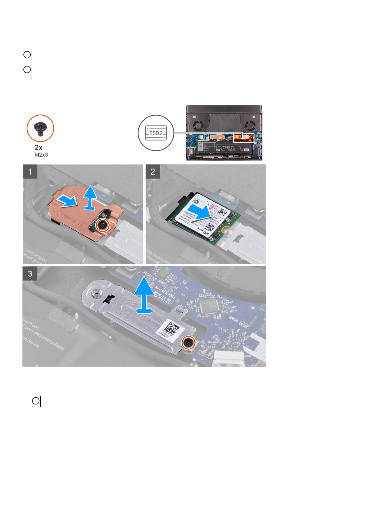
The following image indicates the location of the 2280 solid-state drive in M.2 slot one and provides a visual representation of the
removal procedure.
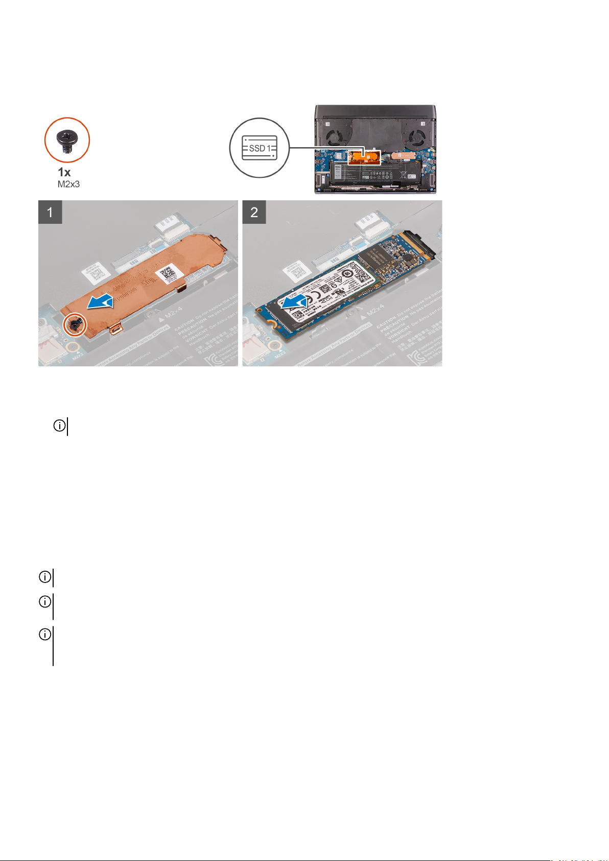
Steps
1. Remove the screw (M2x3) that secures the solid-state drive thermal shield to the palm-rest assembly.
NOTE: A thermal shield is only present if the capacity of the solid-state drive is 512 GB or higher.
2. Lift and remove the solid-state drive thermal shield off the M.2 2280 solid-state drive.
3. Slide and remove the M.2 2280 solid-state drive from the M.2 card slot on the system board.
Installing the 2280 solid-state drive from the M.2 slot one
Prerequisites
If you are replacing a component, remove the existing component before performing the installation procedure.
About this task
NOTE: This procedure applies if you are installing a 2280 solid-state drive in M.2 slot one.
NOTE: Depending on the configuration ordered, your computer may support either 2230 solid-state drive or 2280 solidstate drive in M.2 slot one.
NOTE: A thermal shield is required for optimal heat dissipation if the capacity of the solid-state drive is 512 GB or higher.
If a higher configuration solid-state drive is installed after you purchase the computer, contact Dell support to purchase a
thermal shield.
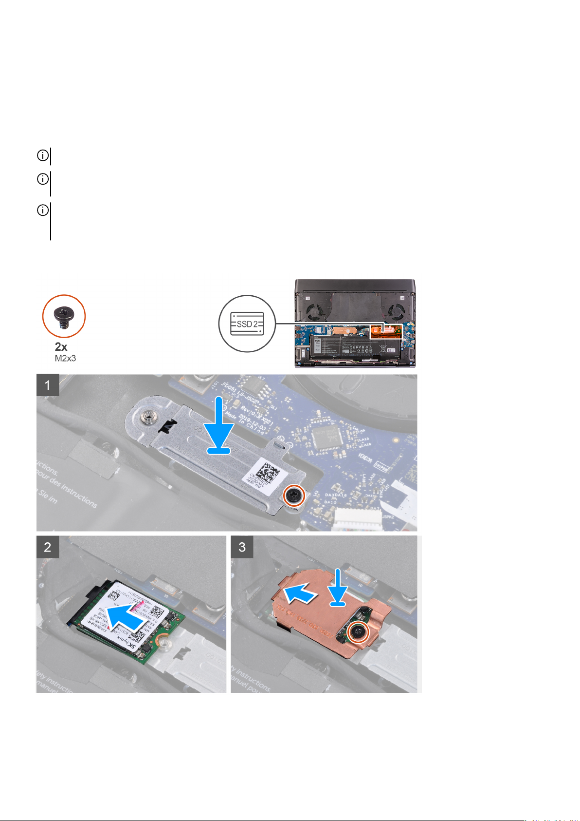
The following image indicates the location of the 2280 solid-state drive and provides a visual representation of the installation
procedure.
15
Page 16
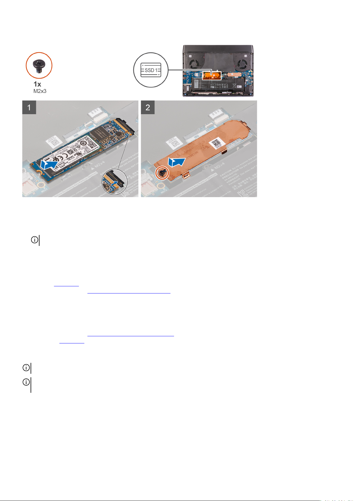
Steps
1. Align the notch on the M.2 2280 solid-state drive with the tab on the M.2 card slot on the system board.
2. Slide the M.2 2280 solid-state drive into the M.2 card slot on the system board.
NOTE: The next step is only applicable if the capacity of the solid-state drive is 512 GB or higher.
3. Slide and align the screw hole of the solid-state drive thermal shield with the screw hole on the palm-rest assembly.
4. Replace the screw (M2x3) that secures the M.2 2280 solid-state drive to the palm-rest assembly.
Next steps
1. Install the base cover.
2. Follow the procedure in After working inside your computer.
Removing the 2230 solid-state drive from the M.2 slot one
Prerequisites
1. Follow the procedure in Before working inside your computer.
2. Remove the
About this task
NOTE: This procedure applies only to computers shipped with a 2230 solid-state drive installed in M.2 slot one.
NOTE: Depending on the configuration ordered, your computer may support either 2230 solid-state drive or 2280 solidstate drive in M.2 slot one.
base cover.
The following image indicates the location of the 2230 solid-state drive that is installed in M.2 slot one and provides a visual
representation of the removal procedure.
16
Page 17
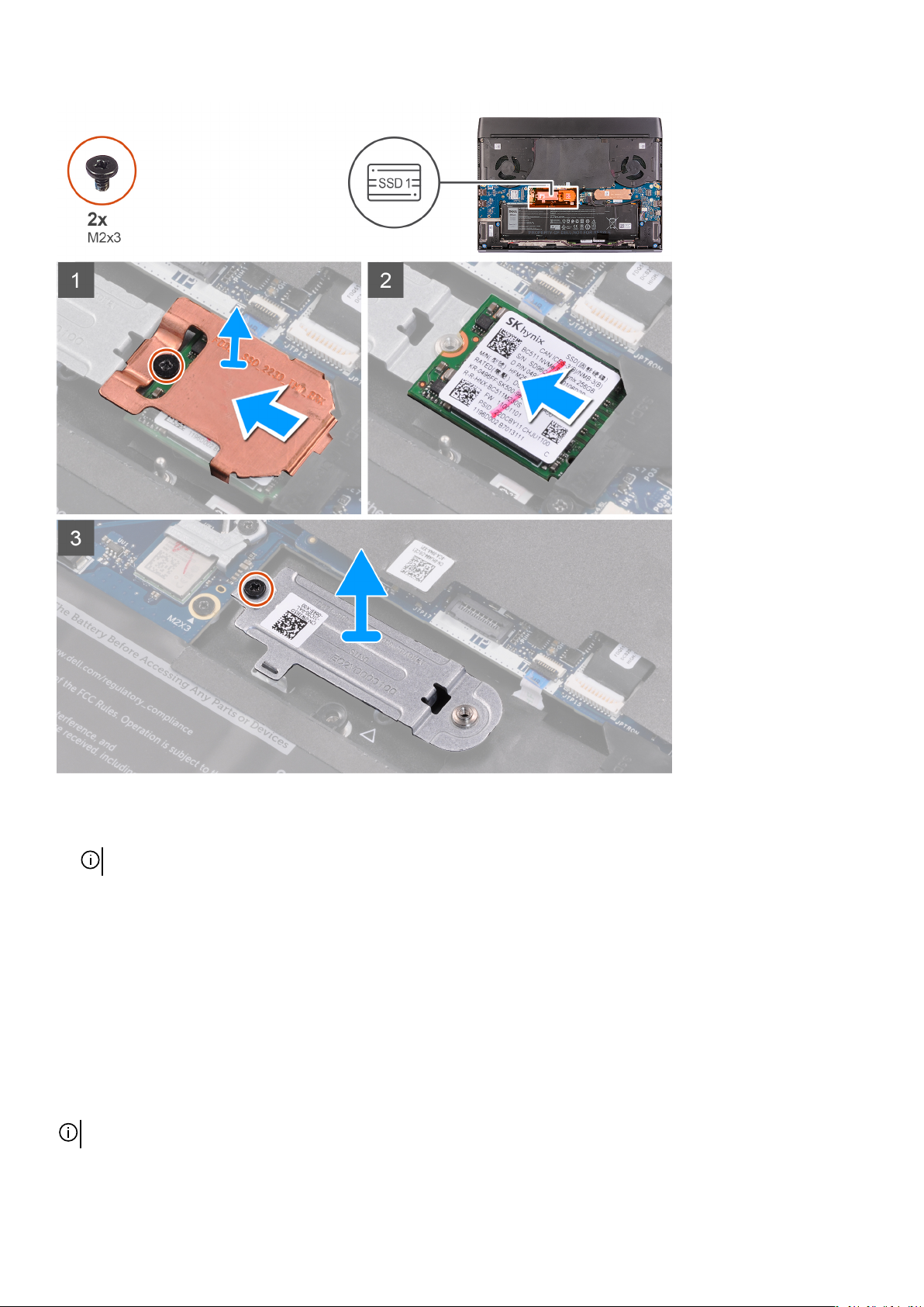
Steps
1. Remove the screw (M2x3) that secures the solid-state drive thermal shield to the M.2 2230 mounting bracket.
NOTE: A thermal shield is only present if the capacity of the solid-state drive is 512 GB or higher.
2. Remove the solid-state drive thermal shield from the M.2 2230 solid-state drive.
3. Lift and remove the M.2 2230 solid-state drive from the M.2 card slot on the system board.
4. Remove the screw (M2x3) that secures the M.2 2230 mounting bracket to the palm-rest assembly.
5. Lift and remove the M.2 2230 mounting bracket from the palm-rest assembly.
Installing the M.2 2230 solid-state drive from the M.2 slot one
Prerequisites
If you are replacing a component, remove the existing component before performing the installation procedure.
About this task
NOTE: This procedure applies if you are installing a 2230 solid-state drive in M.2 slot one.
17
Page 18
NOTE: Depending on the configuration ordered, your computer may support either 2230 solid-state drive or 2280 solidstate drive in M.2 slot one.
NOTE: A thermal shield is required for optimal heat dissipation if the capacity of the solid-state drive is 512 GB or higher.
If a higher configuration solid-state drive is installed after you purchase the computer, contact Dell support to purchase a
thermal shield.
The following image indicates the location of the 2230 solid-state drive that is installed in M.2 slot one and provides a visual
representation of the installation procedure.
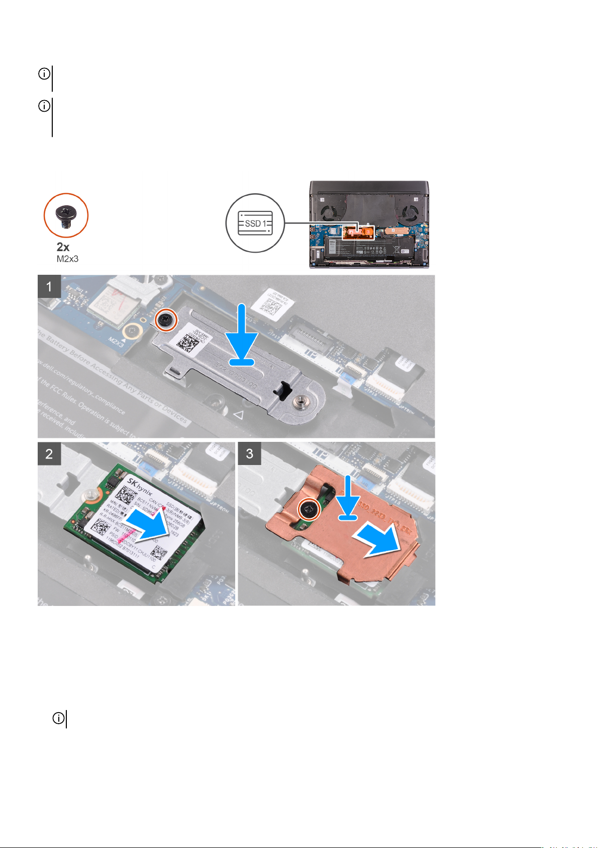
Steps
1. Place and align the M.2 2230 mounting bracket on the palm-rest assembly.
2. Replace the screw (M2x3) that secures the M.2 2230 mounting bracket to the palm-rest assembly.
3. Align the notch on the M.2 2230 solid-state drive with the tab on the M.2 card slot on the system board.
4. Slide the M.2 2230 solid-state drive into the M.2 card slot on the system board.
5. Slide the solid-state drive thermal shield on the M.2 2230 solid-state drive.
NOTE: The next step is only applicable if the capacity of the solid-state drive is 512 GB or higher.
6. Replace the screw (M2x3) that secures the M.2 2230 solid-state drive and the solid-state drive thermal shield to the M.2 2230
mounting bracket.
18
Page 19
Next steps
1. Install the base cover.
2. Follow the procedure in After working inside your computer.
Solid state drive—M.2 slot two
Removing the 2280 solid-state drive from the M.2 slot two
Prerequisites
1. Follow the procedure in Before working inside your computer.
2. Remove the base cover.
About this task
NOTE: This procedure applies only to computers shipped with a 2280 solid-state drive installed in M.2 slot two.
NOTE: Depending on the configuration ordered, your computer may support either 2230 solid-state drive or 2280 solidstate drive in M.2 slot two.
The following image indicates the location of the 2280 solid-state drive that is installed in M.2 slot two and provides a visual
representation of the removal procedure.
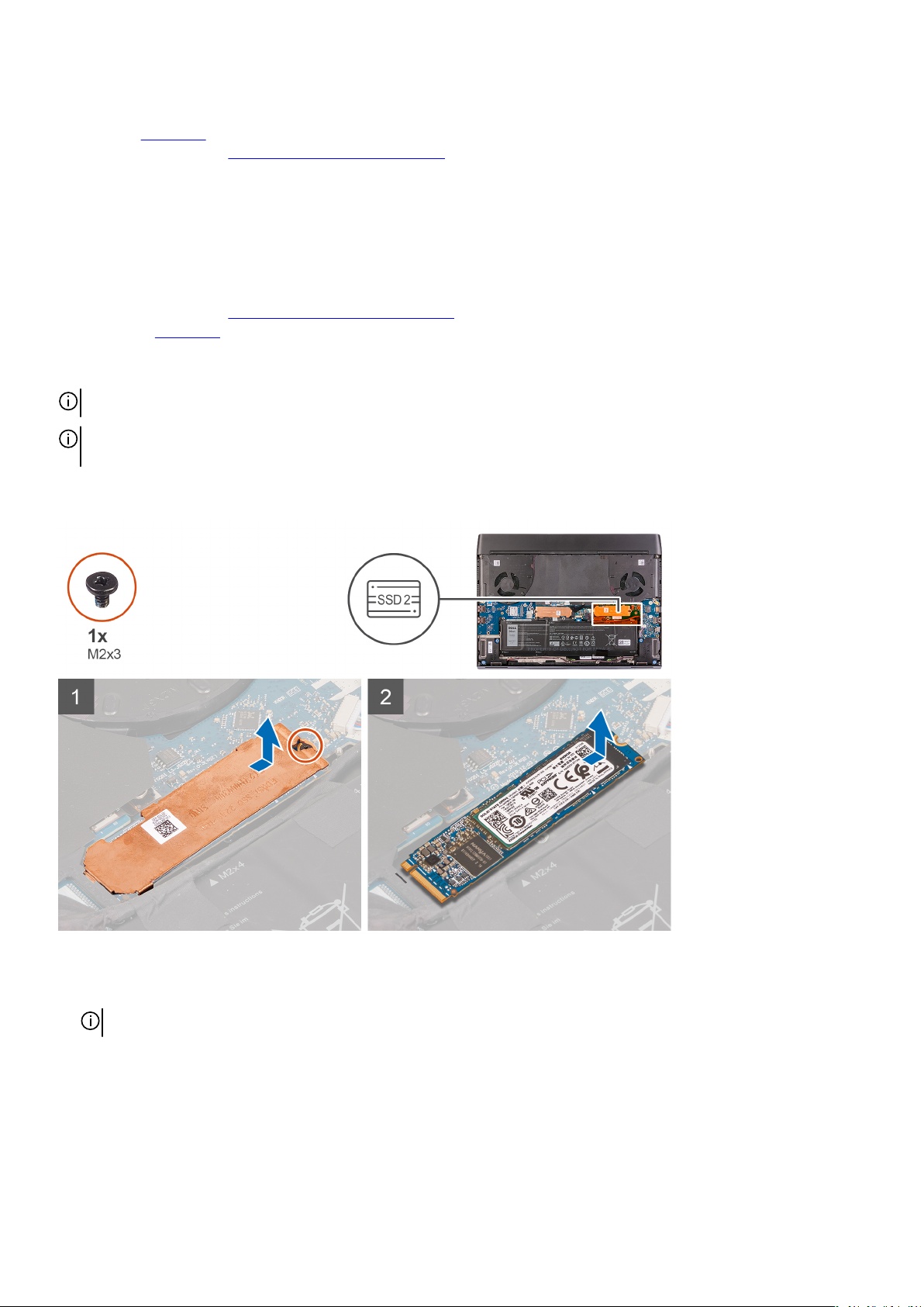
Steps
1. Remove the screw (M2x3) that secures the solid-state drive thermal shield to the palm-rest assembly.
NOTE: A thermal shield is only present if the capacity of the solid-state drive is 512 GB or higher.
2. Lift and remove the solid-state drive thermal shield off the M.2 2280 solid-state drive.
3. Slide and remove the M.2 2280 solid-state drive from the M.2 card slot on the system board.
Installing the 2280 solid-state drive from the M.2 slot two
Prerequisites
If you are replacing a component, remove the existing component before performing the installation procedure.
19
Page 20
About this task
NOTE: This procedure applies if you are installing a 2280 solid-state drive in M.2 slot two.
NOTE: Depending on the configuration ordered, your computer may support either 2230 solid-state drive or 2280 solidstate drive in M.2 slot two.
NOTE: A thermal shield is required for optimal heat dissipation if the capacity of the solid-state drive is 512 GB or higher.
If a higher configuration solid-state drive is installed after you purchase the computer, contact Dell support to purchase a
thermal shield.
The following image indicates the location of the 2280 solid-state drive that is installed in M.2 slot two and provides a visual
representation of the installation procedure.
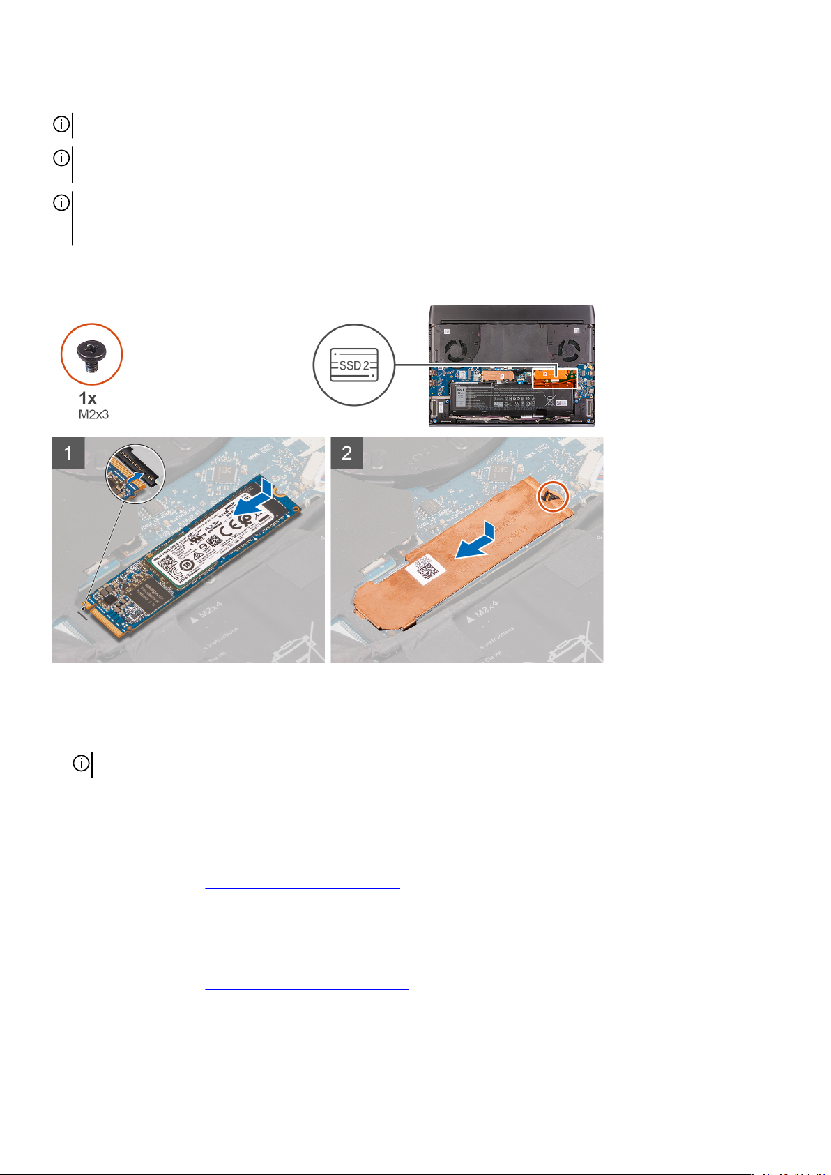
Steps
1. Align the notch on the M.2 2280 solid-state drive with the tab on the M.2 card slot on the system board.
2. Slide the M.2 2280 solid-state drive into the M.2 card slot on the system board.
NOTE: The next step is only applicable if the capacity of the solid-state drive is 512 GB or higher.
3. Slide and align the screw hole of the solid-state drive thermal shield with the screw hole on the palm-rest assembly.
4. Replace the screw (M2x3) that secures the M.2 2280 solid-state drive to the palm-rest assembly.
Next steps
1. Install the base cover.
2. Follow the procedure in After working inside your computer.
Removing the 2230 solid-state drive from the M.2 slot two
Prerequisites
1. Follow the procedure in Before working inside your computer.
2. Remove the base cover.
20
Page 21
About this task
NOTE: This procedure applies only to computers shipped with a 2230 solid-state drive installed in M.2 slot two.
NOTE: Depending on the configuration ordered, your computer may support either 2230 solid-state drive or 2280 solidstate drive in M.2 slot two.
The following image indicates the location of the 2230 solid-state drive that is installed in M.2 slot two and provides a visual
representation of the removal procedure.
Steps
1. Remove the screw (M2x3) that secures the solid-state drive thermal shield to the M.2 2230 mounting bracket.
NOTE: A thermal shield is only present if the capacity of the solid-state drive is 512 GB or higher.
2. Remove the solid-state drive thermal shield from the M.2 2230 solid-state drive.
3. Lift and remove the M.2 2230 solid-state drive from the M.2 card slot on the system board.
4. Remove the screw (M2x3) that secures the M.2 2230 mounting bracket to the palm-rest assembly.
5. Lift and remove the M.2 2230 mounting bracket from the palm-rest assembly.
21
Page 22
Installing the 2230 solid-state drive from the M.2 slot two
Prerequisites
If you are replacing a component, remove the existing component before performing the installation procedure.
About this task
NOTE: This procedure applies if you are installing a 2230 solid-state drive in M.2 slot two.
NOTE: Depending on the configuration ordered, your computer may support either 2230 solid-state drive or 2280 solidstate drive in M.2 slot two.
NOTE: A thermal shield is required for optimal heat dissipation if the capacity of the solid-state drive is 512 GB or higher.
If a higher configuration solid-state drive is installed after you purchase the computer, contact Dell support to purchase a
thermal shield.
The following image indicates the location of the 2230 solid-state drive that is installed in M.2 slot two and provides a visual
representation of the installation procedure.
Steps
1. Place and align the M.2 2230 mounting bracket on the palm-rest assembly.
22
Page 23
2. Replace the screw (M2x3) that secures the M.2 2230 mounting bracket to the palm-rest assembly.
3. Align the notch on the M.2 2230 solid-state drive with the tab on the M.2 card slot on the system board.
4. Slide the M.2 2230 solid-state drive into the M.2 card slot on the system board.
5. Slide the solid-state drive thermal shield on the M.2 2230 solid-state drive.
NOTE: The next step is only applicable if the capacity of the solid-state drive is 512 GB or higher.
6. Replace the two screws (M2x3) that secure the M.2 2230 solid-state drive and the solid-state drive thermal shield to the M.2
2230 mounting bracket.
Next steps
1. Install the base cover.
2. Follow the procedure in After working inside your computer.
Solid state drive—M.2 slot three
Removing the 2230 solid-state drive from the M.2 slot three
Prerequisites
1. Follow the procedure in Before working inside your computer.
2. Remove the base cover.
About this task
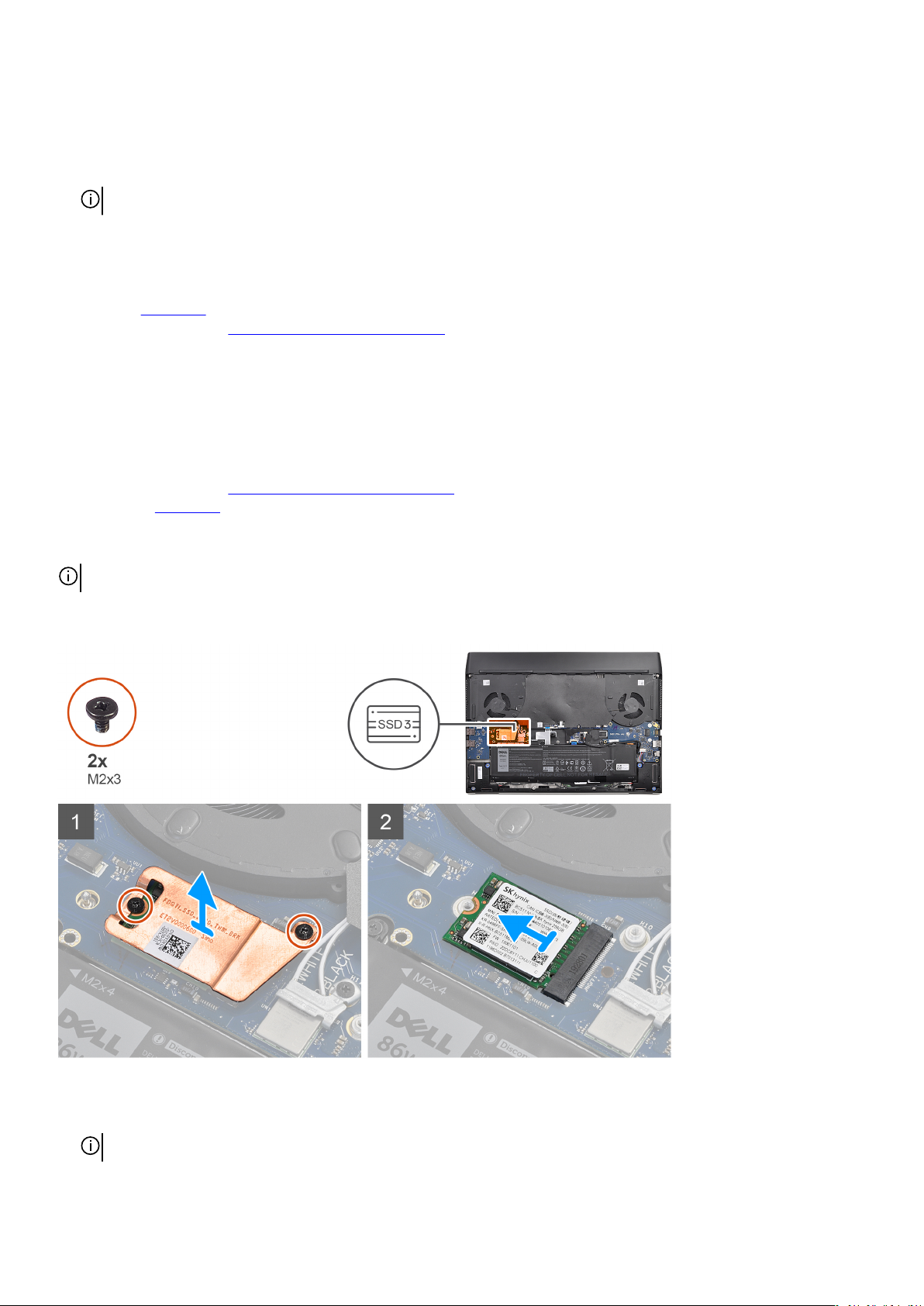
NOTE: M.2 slot three only supports 2230 solid-state drive.
The following image indicates the location of the 2230 solid-state drive that is installed in M.2 slot three and provides a visual
representation of the removal procedure.
Steps
1. Remove the two screws (M2x3) that secure the solid-state drive thermal shield to the system board.
NOTE: A thermal shield is only present if the capacity of the solid-state drive is 512 GB or higher.
2. Remove the solid-state drive thermal shield from the M.2 2230 solid-state drive.
23
Page 24
3. Lift and remove the M.2 2230 solid-state drive from the M.2 card slot on the system board.
Installing the 2230 solid-state drive from the M.2 slot three
Prerequisites
If you are replacing a component, remove the existing component before performing the installation procedure.
About this task
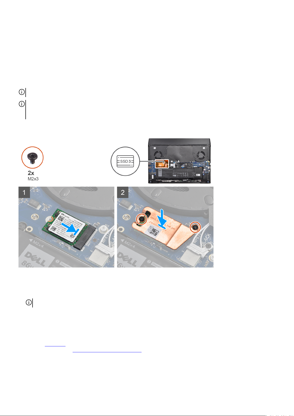
NOTE: M.2 slot three only supports 2230 solid-state drive.
NOTE: A thermal shield is required for optimal heat dissipation if the capacity of the solid-state drive is 512 GB or higher.
If a higher configuration solid-state drive is installed after you purchase the computer, contact Dell support to purchase a
thermal shield.
The following image indicates the location of the 2230 solid-state drive that is installed in M.2 slot three and provides a visual
representation of the installation procedure.
Steps
1. Align the notch on the M.2 2230 solid-state drive with the tab on the M.2 card slot on the system board.
2. Slide the M.2 2230 solid-state drive into the M.2 card slot on the system board.
NOTE: The next step is only applicable if the capacity of the solid-state drive is 512 GB or higher.
3. Place the solid-state drive thermal shield on the M.2 2230 solid-state drive.
4. Replace the two screws (M2x3) that secure the M.2 2230 solid-state drive and the solid-state drive thermal shield to the system
board.
Next steps
1. Install the base cover.
2. Follow the procedure in
24
After working inside your computer.
Page 25

Battery
Lithium-ion battery precautions
CAUTION:
• Exercise caution when handling Lithium-ion batteries.
• Discharge the battery as much as possible before removing it from the system. This can be done by disconnecting the
AC adapter from the system to allow the battery to drain.
• Do not crush, drop, mutilate, or penetrate the battery with foreign objects.
• Do not expose the battery to high temperatures, or disassemble battery packs and cells.
• Do not apply pressure to the surface of the battery.
• Do not bend the battery.
• Do not use tools of any kind to pry on or against the battery.
• Ensure any screws during the servicing of this product are not lost or misplaced, to prevent accidental puncture or
damage to the battery and other system components.
• If the battery gets stuck inside your computer as a result of swelling, do not try to release it as puncturing, bending, or
crushing a lithium-ion battery can be dangerous. In such an instance, contact Dell technical support for assistance. See
www.dell.com/contactdell.
• Always purchase genuine batteries from www.dell.com or authorized Dell partners and resellers.
Removing the battery
Prerequisites
1. Follow the procedure in Before working inside your computer.
2. Remove the base cover.
About this task
CAUTION: This computer is designed without an RTC coin cell-battery. After the battery is disconnected or when the
battery is fully discharged, an RTC reset cycle will occur when you restart the computer. The computer turns on and off
three times. An "Invalid Configuration" error message is displayed prompting you to enter the BIOS and configure the date
and time. The computer starts functioning normally after setting the date and time.
CAUTION: Disconnecting the battery cable resets the BIOS setup program’s settings to default. It is recommended that
you note the BIOS setup program’s settings before removing/disconnecting the battery.
The following image indicates the location of the battery and provides a visual representation of the removal procedure.
25
Page 26

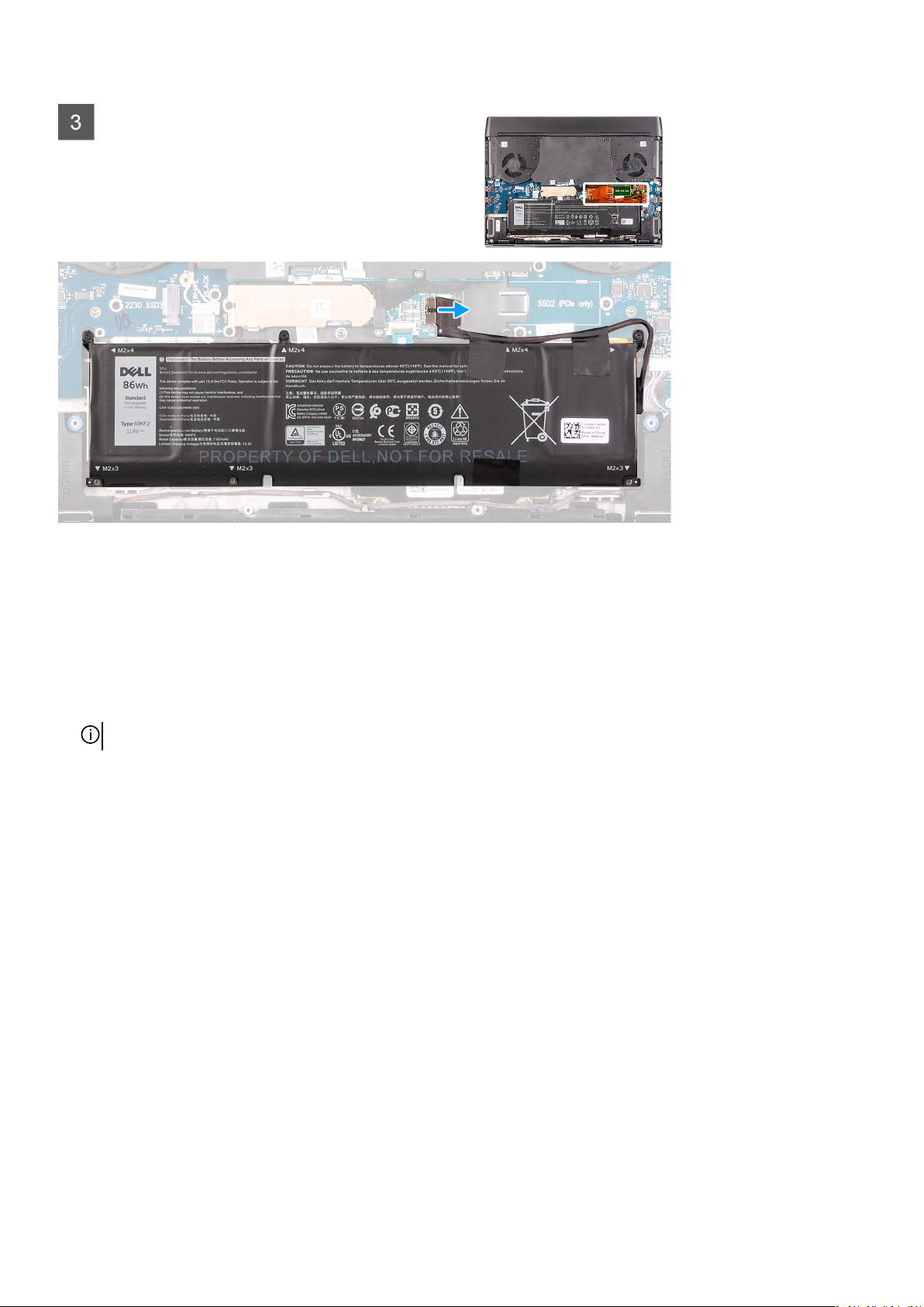
Steps
1. Disconnect the battery cable from the system board, if applicable.
2. Remove the four screws (M2x4) that secure the battery to the palm-rest assembly.
3. Remove the three screws (M2x3) that secure the battery to the palm-rest assembly.
4. Lift the battery up, and then remove it from the palm-rest assembly.
Installing the battery
Prerequisites
If you are replacing a component, remove the existing component before performing the installation procedure.
About this task
The following image indicates the location of the battery and provides a visual representation of the installation procedure.
26
Page 27

Steps
1. Place the battery on the palm-rest assembly.
2. Replace the three screws (M2x3) that secure the battery to the palm-rest assembly.
3. Replace the four screws (M2x4) that secure the battery to the palm-rest assembly.
4. Connect the battery cable to the system board.
Next steps
1. Install the base cover.
2. Follow the procedure in After working inside your computer.
Speakers
Removing the speakers
Prerequisites
1. Follow the procedure in Before working inside your computer.
2. Remove the
About this task
The following image indicates the location of the speakers and provides a visual representation of the removal procedure.
base cover.
27
Page 28

Steps
1. Disconnect the speaker cable from the right I/O-board.
2. Lift the right speaker off the palm-rest assembly.
3. Remove the speaker cables from the routing guides on the palm-rest assembly.
4. Lift the left speaker off the palm-rest assembly.
Installing the speakers
Prerequisites
If you are replacing a component, remove the existing component before performing the installation procedure.
About this task
The following image indicates the location of the speakers and provides a visual representation of the installation procedure.
28
Page 29

Steps
1. Using the alignment posts, place the left speaker on the palm-rest assembly.
NOTE: Ensure that the alignment posts on the palm-rest and keyboard assembly are threaded through the rubber
grommets on the speaker.
NOTE: If the rubber grommets are pushed out of the speakers when removing the speakers, push them back in place
before replacing the speakers.
2. Route the speaker cable through the routing guides on the palm-rest assembly.
3. Using the alignment posts, place the right speaker on the palm-rest assembly.
NOTE: Ensure that the alignment posts on the palm-rest and keyboard assembly are threaded through the rubber
grommets on the speaker.
NOTE: If the rubber grommets are pushed out of the speakers when removing the speakers, push them back in place
before replacing the speakers.
4. Connect the speaker cable to the right I/O-board.
Next steps
1. Install the
2. Follow the procedure in After working inside your computer.
base cover.
Keyboard-controller board
Removing the keyboard-controller board
Prerequisites
1. Follow the procedure in
2. Remove the
3. Remove the battery.
base cover.
Before working inside your computer.
29
Page 30

About this task
The following image indicates the location of the keyboard-controller board and provides a visual representation of the removal
procedure.
Steps
1. Open the latch, and disconnect the keyboard-backlight cable from the keyboard-controller board.
2. Open the latch, and disconnect the keyboard-controller board cable from the keyboard-controller board.
3. Open the latch, and disconnect the keyboard cable from the keyboard-controller board.
4. Remove the two screws (M2x1.9) that secure the keyboard-controller board to the palm-rest assembly.
5. Lift the keyboard-controller board from the palm-rest assembly.
Installing the keyboard-controller board
Prerequisites
If you are replacing a component, remove the existing component before performing the installation procedure.
About this task
NOTE: After replacing the keyboard-controller board, select the keyboard language from the System Setup to ensure
keyboard works optimally.
The following image indicates the location of the keyboard-controller board and provides a visual representation of the installation
procedure.
30
Page 31

Steps
1. Using the alignment pins, place the keyboard-controller board into place on the palm-rest assembly.
2. Align the screw holes on the keyboard-controller board with the screw holes on the palm-rest assembly.
3. Connect the keyboard-controller board cable to the keyboard-controller board and close the latch.
4. Connect the keyboard cable to the keyboard-controller board and close the latch.
5. Connect the keyboard-backlight cable to the keyboard-controller board and close the latch.
6. Replace the two screws (M2x1.9) that secure the keyboard-controller board to the palm-rest assembly.
Next steps
1. Install the
2. Install the base cover.
3. Follow the procedure in
battery.
After working inside your computer.
Touchpad
Removing the touchpad
Prerequisites
1. Follow the procedure in
2. Remove the
3. Remove the battery.
base cover.
Before working inside your computer.
About this task
The following image indicates the location of the touchpad and provides a visual representation of the removal procedure.
31
Page 32

Steps
1. Open the latch, and disconnect the keyboard-controller board-cable from keyboard-controller board.
2. Open the latch, and disconnect the keyboard-controller board-cable from system board.
3. Lift the keyboard-controller board-cable off the palm-rest assembly.
4. Open the latch, and disconnect the keyboard cable from the keyboard-controller board.
5. Fold up the keyboard cable.
6. Open the latch, and disconnect the touchpad cable from the touchpad.
7. Lift the touchpad cable from the palm-rest assembly.
8. Remove the four (M2x2.5) screws that secure the touchpad to the palm-rest assembly.
9. Peel off the tape that secures the touchpad to the palm-rest assembly.
10.Lift the touchpad off the palm-rest assembly.
Installing the touchpad
Prerequisites
If you are replacing a component, remove the existing component before performing the installation procedure.
32
Page 33

About this task
The following image indicates the location of the touchpad and provides a visual representation of the installation procedure.
Steps
1. Place the touchpad into the slot on the palm-rest assembly.
NOTE: Turn the computer over, and open the display. Ensure that the touchpad is equally aligned along all four sides.
2. Replace the four (M2x2.5) screws that secure the touchpad to the palm-rest assembly.
3. Adhere the tape that secures the touchpad to the palm-rest assembly.
4. Connect the touchpad cable to the touchpad, and close the latch.
NOTE: This step is only applicable when the touchpad cable is not being replaced.
5. Fold down the keyboard cable.
6. Connect the keyboard cable to the keyboard-controller board and close the latch.
7. Connect the keyboard-controller board cable to the keyboard-controller board and close the latch.
8. Connect the keyboard-controller board cable to the system board and close the latch.
Next steps
1. Install the battery.
33
Page 34

2. Install the base cover.
3. Follow the procedure in After working inside your computer.
Rear-I/O cover
Removing the rear I/O-cover
Prerequisites
1. Follow the procedure in Before working inside your computer.
2. Remove the base cover.
About this task
The following image indicates the location of the rear I/O-cover and provides a visual representation of the removal procedure.
34
Page 35

Steps
1. Peel and remove the Mylar that covers the system board.
2. Disconnect and peel the Tron-light cable from the system board.
CAUTION: To prevent damaging your computer, ensure that the Tron-light cable has been disconnected from the
system board before removing the rear I/O-cover.
3. Remove the two screws (M2.5x5) that secure the rear I/O-cover to the palm-rest assembly.
4. Remove the two screws (M2x4.5) that secure the rear I/O-cover to the palm-rest assembly.
5. Firmly grasp the sides of your computer with both hands and push the rubber feet on the rear I/O-cover outwards with your
thumbs to release the rear I/O-cover from the palm-rest assembly.
6. Lift the rear I/O-cover from the palm-rest assembly.
Installing the rear I/O-cover
Prerequisites
If you are replacing a component, remove the existing component before performing the installation procedure.
About this task
The following image indicates the location of the rear I/O-cover and provides a visual representation of the installation procedure.
35
Page 36

36
Page 37

Steps
1. Adhere the Mylar into place onto the system board.
2. Push the rear I/O-cover into the palm-rest assembly snapping it into place.
NOTE: To avoid damaging your computer, ensure that the Tron light cable is not pinched and that the Mylar is pasted on
the system board before snapping the rear I/O-cover into place.
3. Replace the two screws (M2x4.5) that secure the rear I/O-cover to the palm-rest assembly.
4. Replace the two screws (M2.5x5) that secure the rear I/O-cover to the palm-rest assembly.
5. Connect the Tron light cable to the system board.
6. Route and adhere the Tron light cable into place on the system board underneath the mylar.
Next steps
1. Install the
2. Follow the procedure in After working inside your computer.
base cover.
Display assembly
Removing the display assembly
Prerequisites
1. Follow the procedure in Before working inside your computer.
2. Remove the base cover.
3. Remove the rear I/O-cover.
About this task
NOTE: The display assembly is a Hinge-up Display (HUD) and cannot be further disassembled.
The following image indicates the location of the display assembly and provides a visual representation of the removal procedure.
37
Page 38

38
Page 39

Steps
1. Remove the screw (M2x3) that secures the wireless card bracket to the left I/O-board.
2. Lift the wireless card bracket off the left I/O-board.
3. Disconnect the antenna cables from the wireless card.
4. Peel the tapes securing the antenna cables to system board and left fan.
5. Remove the antenna cables from the routing guides on the left fan and system board.
6. Peel the tapes securing the display cable to the system board.
7. Open the latch, and disconnect the display cable from the connector on the system board.
8. Disconnect the G-sensor cable from the connector on the system board.
9. Disconnect the Tobii eye tracker cable from the connector on the system board.
NOTE: This step is only applicable to computers shipped with a Tobii eye tracker.
10.Place the computer face up.
CAUTION: Place the computer on a soft and clean surface to avoid scratching the display.
11. Remove the following cables from the routing guides on the palm-rest assembly.
• Display cable
• G-sensor cable
• Tobii eye tracker cable
• Antenna cables
39
Page 40

12. Remove the six screws (M2.5x5) securing the display assembly to the palm-rest assembly.
13. Gently lift the display assembly from the palm-rest assembly.
Installing the display assembly
Prerequisites
If you are replacing a component, remove the existing component before performing the installation procedure.
About this task
CAUTION: Place the computer on a soft and clean surface to avoid scratching the display.
NOTE: The display assembly is a Hinge-up Display (HUD) and cannot be further disassembled. If components within the
display assembly must be replaced, the entire display assembly is to be replaced.
The following image indicates the location of the display assembly and provides a visual representation of the installation procedure.
40
Page 41

Steps
1. Ensure that the palm-rest assembly is placed face up with the keyboard facing you.
2. Gently place the display assembly on the palm-rest assembly and align the screw holes on the display assembly to the screw holes
on the palm-rest assembly.
3. Replace the six screws (M2.5x5) that secure the display assembly to the palm-rest assembly.
4. Route the following cables to the routing guides on the palm-rest assembly.
• Display cable
• G-sensor cable
• Tobii eye tracker cable
• Antenna cables
5. Place the computer face down.
6. Connect the Tobii eye tracker cable to the connector on the system board.
NOTE: This step is only applicable to computers shipped with a Tobii eye tracker.
7. Connect the G-sensor cable to the connector on the system board.
8. Connect the display cable to the connector on the system board and close the latch.
9. Route the antenna cables to the routing guides on the left fan and system board.
10.Adhere the tapes that secure the antenna cables to system board and left fan.
11. Connect the antenna cables to the wireless card.
41
Page 42

The following table provides the antenna-cable color scheme for the wireless card that is supported by your computer.
Table 2. Antenna-cable color scheme
Connectors on the wireless card Antenna-cable color
Main (white triangle) White
Auxiliary (black triangle) Black
12. Place the wireless card bracket on the wireless card.
13. Replace the screw (M2x3) that secures the wireless card bracket to the left I/O-board.
Next steps
1. Install the rear I/O-cover.
2. Install the base cover.
3. Follow the procedure in
After working inside your computer.
Right I/O-board
Removing the right I/O-board
Prerequisites
1. Follow the procedure in
2. Remove the base cover.
3. Remove the
4. Remove the 2230 solid-date drive in M.2 slot two, if installed.
5. Remove the 2280 solid-date drive in M.2 slot two, if installed.
battery.
Before working inside your computer.
About this task
The following image indicates the location of the right I/O-board and provides a visual representation of the removal procedure.
42
Page 43

Steps
1. Lift the Mylar that covers the system board and right-I/O board.
2. Remove the two screws (M2x3) that secure the right I/O-board cable connecting the right I/O-board and the system board.
3. Lift the right I/O-board cable off the right I/O-board and system board.
4. Disconnect the speaker cable from the right I/O-board.
5. Remove the three screws (M2x3) that secure the right I/O-board to the palm-rest assembly.
6. Lift the right I/O-board off the palm-rest assembly.
Installing the right I/O-board
Prerequisites
If you are replacing a component, remove the existing component before performing the installation procedure.
About this task
The following image indicates the location of the right I/O-board and provides a visual representation of the installation procedure.
43
Page 44

Steps
1. Place the right I/O-board on the palm-rest assembly.
2. Align the screw holes on the right I/O-board with the screw holes on the palm-rest assembly.
3. Replace the three screws (M2x3) that secure the right I/O-board to the palm-rest assembly.
4. Connect the speaker cable to the connector on the right I/O-board.
5. Using the alignment pins, connect the right I/O-board cable on the right I/O-board and the system board.
NOTE: The I/O-board cable is polarity sensitive. To prevent damage to your computer, ensure that the MB UMT end of
the cable is connected to the system board.
6. Replace the two screws (M2x3) that secure the right I/O-board cable to the right I/O-board and system board.
Next steps
1. Install the
2. Install the 2230 solid-state drive in M.2 slot two, if installed.
3. Install the
4. Install the base cover.
5. Follow the procedure in After working inside your computer.
44
2280 solid-state drive in M.2 slot two, if installed.
battery.
Page 45

System board
Removing the system board
Prerequisites
1. Follow the procedure in
2. Remove the base cover.
3. Remove the 2230 solid-state drive in M.2 slot one, if installed.
4. Remove the
5. Remove the 2230 solid-state drive in M.2 slot two, if installed.
6. Remove the 2280 solid-state drive in M.2 slot two, if installed.
7. Remove the
8. Remove the battery.
About this task
The following image indicates the location of the system board and provides a visual representation of the removal procedure.
2280 solid-state drive in M.2 slot one, if installed.
rear I/O-cover.
Before working inside your computer.
45
Page 46

Steps
1. Remove the screw (M2x3) that secures the wireless card bracket to the left I/O-board.
2. Lift the wireless-card bracket off the left I/O-board.
3. Disconnect the antenna cables from the wireless card.
4. Peel the tapes securing the antenna cables to system board and left fan.
5. Remove the antenna cables from the routing guides on the left fan.
6. Open the latch, and disconnect the power-button cable from the left I/O-board.
7. Open the latch, and disconnect the touchpad cable from the system board.
8. Open the latch, and disconnect the keyboard-controller board-cable from the system board.
9. Remove the three screws (M2x4.5) that secure the solid-state drive support bracket to the system board.
10.Remove the solid-state drive support bracket from the system board.
11. Remove the two screws (M2x3) that secure the right I/O-board cable to the right I/O-board and the system board.
12. Lift the right I/O-board cable off the right I/O-board and the system board.
13. Disconnect the power-adapter port cable from the system board.
14. Open the latch, and disconnect the display cable from the connector on the system board.
15.Disconnect the G-sensor cable from the connector on the system board.
16.Disconnect the Tobii eye tracker cable from the connector on the system board.
46
Page 47

NOTE: This step is only applicable to computers shipped with a Tobii eye tracker.
17. Remove the two (M2.5x5) screws that secure the fans to the palm-rest assembly.
18.Remove the five (M2x3) screws that secure the system board to the palm-rest assembly.
19.Remove the three (M2x3) screws that secure the left I/O-board to the palm-rest assembly.
20.Lift the system board and the left I/O-board out of the palm-rest assembly.
21. Turn the system board over.
22.Remove the
23.Remove the fan and heat-sink assembly.
left I/O-board.
Installing the system board
Prerequisites
If you are replacing a component, remove the existing component before performing the installation procedure.
About this task
The following image indicates the location of the system board and provides a visual representation of the removal procedure.
47
Page 48

Steps
1. Install the fan and heat-sink assembly.
2. Install the left I/O-board.
3. Turn the system board over, place the system board and the left I/O-board on the palm-rest assembly.
4. Replace the two (M2.5x5) screws that secure the fans to the palm-rest assembly.
5. Replace the five (M2x3) screws that secure the system board to the palm-rest assembly.
6. Replace the three (M2x3) screws that secure the left I/O-board to the palm-rest assembly.
7. Connect the Tobii eye tracker cable to the connector on the system board.
NOTE: This step is only applicable to computers shipped with a Tobii eye tracker.
8. Connect the G-sensor cable to the connector on the system board.
9. Connect the display cable to the connector on the system board and close the latch.
10.Connect the power-adapter port cable from the system board.
11. Using the alignment pins, connect the right I/O-board cable to the right I/O-board and the system board.
NOTE: The I/O-board cable is polarity sensitive. To prevent damage to your computer ensure that the MB UMT end of
the cable is connected to the system board.
12. Replace the two screws (M2x3) that secure the right I/O-board cable to the right I/O-board and the system board.
48
Page 49

13. Using the tab on the solid-state drive support bracket and the slot on the system board, align the screw hole of the solid-state
drive support bracket with the screw hole on the system board.
14. Replace the three screws (M2x4.5) that secure the solid-state drive support bracket to the system board.
15.Connect the keyboard-controller board-cable to the system board and close the latch.
16.Connect the touchpad cable to the system board and close the latch.
17. Connect the power-button cable to the system board.
18.Route the antenna cables to the routing guides on the left fan and system board.
19.Adhere the tapes that secure the antenna cables to system board and left fan.
20.Connect the antenna cables to the wireless card.
The following table provides the antenna-cable color scheme for the wireless card that is supported by your computer.
Table 3. Antenna-cable color scheme
Connectors on the wireless card Antenna-cable color
Main (white triangle) White
Auxiliary (black triangle) Black
21. Place the wireless card bracket on the wireless card.
22.Replace the screw (M2x3) that secures the wireless card bracket to the left I/O-board.
Next steps
1. Install the battery.
2. Install the rear I/O-cover.
3. Install the 2280 solid-state drive in M.2 slot two, if installed.
4. Install the
5. Install the 2280 solid-state drive in M.2 slot one, if installed.
6. Install the 2230 solid-state drive in M.2 slot one, if installed.
7. Install the base cover.
8. Follow the procedure in
2230 solid-state drive in M.2 slot two, if installed.
After working inside your computer.
Left I/O-board
Removing the left I/O-board
Prerequisites
1. Follow the procedure in Before working inside your computer.
2. Remove the base cover.
3. Remove the 2230 solid-state drive in M.2 slot one, if installed.
4. Remove the 2280 solid-state drive in M.2 slot one, if installed.
5. Remove the
6. Remove the 2280 solid-state drive in M.2 slot two, if installed.
7. Remove the rear I/O-cover.
8. Remove the battery.
9. Follow step 1 to step 21 in removing the system board.
About this task
CAUTION: The interposer board is installed between the left I/O-board and system board. Remove the interposer board
immediately after removing the left I/O-board and keep it in a clean and safe place. Handle the board by lifting and
holding from the edges or the sides as the pins on the interposer board are fragile.
The following image indicates the location of the left I/O-board and provides a visual representation of the removal procedure.
2230 solid-state drive in M.2 slot two, if installed.
49
Page 50

Steps
1. Remove the four screws (M2x4.5) that secure the left I/O-board to the system board.
2. Lift the left I/O-board off the system board.
3. Lift the interposer board off the system board.
NOTE: The interposer may come off with the I/O board.
Installing the left I/O-board
Prerequisites
If you are replacing a component, remove the existing component before performing the installation procedure.
About this task
CAUTION: The interposer board is installed between the left I/O-board and system board. Install the interposer board
before installing the left I/O-board. Handle the board by lifting and holding from the edges or the sides as the pins on the
interposer board are fragile.
The following image indicates the location of the left I/O-board and provides a visual representation of the installation procedure.
50
Page 51

Steps
1. Using the alignment pins, place the interposer board on the system board.
2. Using the alignment pins, connect the left I/O-board to the system board through the interposer board.
3. Align the screw holes on the left I/O-board with the screw holes on the system board and interposer board.
4. Replace the four screws (M2x4.5) that secure the left I/O-board to the system board.
Next steps
1. Follow step 3 to step 22 in installing the
2. Install the battery.
3. Install the rear I/O-cover.
4. Install the 2280 solid-state drive in M.2 slot two, if installed.
5. Install the
6. Install the 2280 solid-state drive in M.2 slot one, if installed.
7. Install the 2230 solid-state drive in M.2 slot one, if installed.
8. Install the base cover.
9. Follow the procedure in
2230 solid-state drive in M.2 slot two, if installed.
After working inside your computer.
system board.
Fan and heat-sink assembly
Removing the fan and heat-sink assembly
Prerequisites
1. Follow the procedure in
2. Remove the base cover.
3. Remove the
4. Remove the 2280 solid-state drive in M.2 slot one, if installed.
5. Remove the 2230 solid-state drive in M.2 slot two, if installed.
6. Remove the 2280 solid-state drive in M.2 slot two, if installed.
7. Remove the rear I/O-cover.
8. Remove the battery.
9. Follow step 1 to step 21 in removing the system board.
2230 solid-state drive in M.2 slot one, if installed.
Before working inside your computer.
51
Page 52

About this task
NOTE: The heat sink may become hot during normal operation. Allow sufficient time for the heat sink to cool before you
touch it.
CAUTION: For maximum cooling of the processor, do not touch the heat transfer areas on the heat sink. The oils in your
skin can reduce the heat transfer capability of the thermal grease.
The following image indicates the location of the fan and heat-sink assembly and provides a visual representation of the removal
procedure.
52
Page 53

Steps
1. Disconnect the left and right fan cables from the system board.
2. In the reverse sequential order (10>9>8>7>6>5>4>3>2>1), remove the ten screws (M2x3) that secure the fan and heat-sink
assembly to the system board.
NOTE: The number of screws varies depending on the configuration ordered.
3. Using the pull tab, lift the fan and heat-sink assembly from the system board.
Installing the fan and heat-sink assembly
Prerequisites
If you are replacing a component, remove the existing component before performing the installation procedure.
CAUTION: If either the processor or the heat sink is replaced, use the thermal grease that is provided in the kit to ensure
that the thermal conductivity is achieved.
About this task
The following image indicates the location of the fan and heat-sink assembly and provides a visual representation of the installation
procedure.
53
Page 54

Steps
1. Place the fan and heat-sink assembly on the system board.
2. In sequential order (1>2>3>4>5>6>7>8>9>10), replace the ten screws (M2x3) that secure the fan and heat-sink assembly to
the system board.
NOTE: The number of screws varies depending on the configuration ordered.
3. Connect the left and right fan cables to the system board.
Next steps
1. Follow step 3 to step 22 in installing the system board.
2. Install the battery.
3. Install the rear I/O-cover.
4. Install the 2280 solid-state drive in M.2 slot two, if installed.
5. Install the
6. Install the 2280 solid-state drive in M.2 slot one, if installed.
7. Install the 2230 solid-state drive in M.2 slot one, if installed.
8. Install the base cover.
9. Follow the procedure in
2230 solid-state drive in M.2 slot two, if installed.
After working inside your computer.
Power-adapter port
Removing the power-adapter port
Prerequisites
1. Follow the procedure in
2. Remove the base cover.
3. Remove the
4. Remove the 2280 solid-state drive in M.2 slot one, if installed.
5. Remove the 2230 solid-state drive in M.2 slot two, if installed.
6. Remove the 2280 solid-state drive in M.2 slot two, if installed.
7. Remove the rear I/O-cover.
8. Remove the battery.
54
2230 solid-state drive in M.2 slot one, if installed.
Before working inside your computer.
Page 55

9. Follow step 1 to step 21 in removing the system board.
About this task
The following image indicates the location of the power-adapter port and provides a visual representation of the removal procedure.
Steps
1. Remove the two screws (M2x3) that secure the power-adapter port bracket to the palm-rest assembly.
2. Lift the power-adapter port bracket off the palm-rest assembly.
3. Lift the power-adapter port along with its cable off the palm-rest assembly.
Installing the power-adapter port
Prerequisites
If you are replacing a component, remove the existing component before performing the installation procedure.
About this task
The following image indicates the location of the power-adapter port and provides a visual representation of the installation
procedure.
55
Page 56

Steps
1. Place the power-adapter port into the slot on the palm-rest assembly.
2. Place the power-adapter port bracket on the power-adapter port.
3. Replace the two screws (M2x3) that secure the power-adapter port bracket to the palm-rest assembly.
Next steps
1. Follow step 3 to step 22 in installing the
2. Install the battery.
3. Install the rear I/O-cover.
4. Install the 2280 solid-state drive in M.2 slot two, if installed.
5. Install the 2230 solid-state drive in M.2 slot two, if installed.
6. Install the
7. Install the 2230 solid-state drive in M.2 slot one, if installed.
8. Install the base cover.
9. Follow the procedure in After working inside your computer.
2280 solid-state drive in M.2 slot one, if installed.
system board.
Power-button assembly
Removing the power-button assembly
Prerequisites
1. Follow the procedure in Before working inside your computer.
2. Remove the base cover.
3. Remove the 2230 solid-state drive in M.2 slot one, if installed.
4. Remove the 2280 solid-state drive in M.2 slot one, if installed.
5. Remove the
6. Remove the 2280 solid-state drive in M.2 slot two, if installed.
7. Remove the rear I/O-cover.
8. Remove the battery.
9. Remove the right I/O-board.
10.Follow step 1 to step 21 in removing the system board.
2230 solid-state drive in M.2 slot two, if installed.
56
Page 57

About this task
The following image indicates the location of the power-button assembly and provides a visual representation of the removal
procedure.
Steps
1. Remove the two (M2x1.9) screws that secure the power-button bracket to the palm-rest assembly.
2. Lift the power-button bracket off the power-button assembly.
3. Peel the power-button assembly and its cable off the palm-rest assembly.
Installing the power-button assembly
Prerequisites
If you are replacing a component, remove the existing component before performing the installation procedure.
About this task
The following image indicates the location of the power-button assembly and provides a visual representation of the installation
procedure.
57
Page 58

Steps
1. Place the power-button assembly and its cable in the slot on the palm-rest assembly.
2. Place the power-button bracket on the power-button assembly.
3. Replace the two (M2x1.9) screws that secure the power-button bracket to the palm-rest assembly.
Next steps
1. Follow step 3 to step 22 in installing the
2. Install the right I/O-board.
3. Install the battery.
4. Install the rear I/O-cover.
5. Install the 2280 solid-state drive in M.2 slot two, if installed.
6. Install the
7. Install the 2280 solid-state drive in M.2 slot one, if installed.
8. Install the 2230 solid-state drive in M.2 slot one, if installed.
9. Install the base cover.
10.Follow the procedure in
2230 solid-state drive in M.2 slot two, if installed.
After working inside your computer.
system board.
Keyboard
Removing the keyboard
Prerequisites
1. Follow the procedure in
2. Remove the base cover.
3. Remove the
4. Remove the 2280 solid-state drive in M.2 slot one, if installed.
5. Remove the 2230 solid-state drive in M.2 slot two, if installed.
6. Remove the 2280 solid-state drive in M.2 slot two, if installed.
7. Remove the rear I/O-cover.
8. Remove the battery.
9. Remove the right I/O-board.
2230 solid-state drive in M.2 slot one, if installed.
Before working inside your computer.
58
Page 59

10.Follow step 1 to step 21 in removing the system board.
About this task
The following image indicates the location of the keyboard and provides a visual representation of the removal procedure.
59
Page 60

Steps
1. Open the latch, and disconnect the keyboard-backlight cable from the keyboard-controller board.
2. Open the latch, and disconnect the keyboard cable from the keyboard-controller board.
3. Remove the ten (M1.2x2.1) screws that secure the keyboard bracket to the keyboard.
4. Lift the keyboard bracket off the keyboard.
5. Remove the 28 (M1.2x1.6) screws that secure the keyboard to the palm-rest assembly.
6. Lift the keyboard off the palm-rest assembly.
Installing the keyboard
Prerequisites
If you are replacing a component, remove the existing component before performing the installation procedure.
About this task
The following image indicates the location of the keyboard and provides a visual representation of the installation procedure.
60
Page 61

61
Page 62

Steps
1. Place the keyboard on the palm-rest assembly.
2. Replace the 28 (M1.2x1.6) screws that secure the keyboard to the palm-rest assembly.
NOTE: The 28 screw holes are marked with an arrow.
3. Place the keyboard bracket on the keyboard.
4. Replace the ten (M1.2x2.1) screws that secure the keyboard bracket to the keyboard.
5. Connect the keyboard cable to the keyboard-controller board and close the latch.
6. Connect the keyboard-backlight cable to the keyboard, and close the latch.
Next steps
1. Follow step 3 to step 22 in installing the
2. Install the right I/O-board.
3. Install the
4. Install the rear I/O-cover.
5. Install the 2280 solid-state drive in M.2 slot two, if installed.
6. Install the 2230 solid-state drive in M.2 slot two, if installed.
7. Install the 2280 solid-state drive in M.2 slot one, if installed.
8. Install the
9. Install the base cover.
10.Follow the procedure in After working inside your computer.
battery.
2230 solid-state drive in M.2 slot one, if installed.
system board.
Palmrest
Removing the palm rest
Prerequisites
1. Follow the procedure in Before working inside your computer.
2. Remove the base cover.
3. Remove the 2230 solid-state drive in M.2 slot one, if installed.
4. Remove the 2280 solid-state drive in M.2 slot one, if installed.
5. Remove the 2230 solid-state drive in M.2 slot two, if installed.
62
Page 63

6. Remove the 2280 solid-state drive in M.2 slot two, if installed.
7. Remove the speakers.
8. Remove the rear I/O-cover.
9. Remove the battery.
10.Remove the
11. Remove the keyboard-controller board.
12. Remove the right I/O-board.
13. Follow step 1 to step 21 in removing the
14. Remove the touchpad.
15.Remove the power-adapter port.
16.Remove the power-button assembly.
17. Remove the keyboard.
Steps
After performing the pre-requisites, you are left with the palm rest.
display assembly.
system board.
Installing the palm rest
Prerequisites
If you are replacing a component, remove the existing component before performing the installation procedure.
Steps
To install the palm rest, perform the post-requisites.
63
Page 64

Next steps
1. Install the
2. Install the
3. Install the power-adapter port.
4. Install the touchpad.
5. Follow step 3 to step 22 in installing the system board.
6. Install the right I/O-board.
7. Install the
8. Install the display assembly.
9. Install the battery.
10.Install the rear I/O-cover.
11. Install the
12. Install the 2280 solid-state drive in M.2 slot two, if installed.
13. Install the 2230 solid-state drive in M.2 slot two, if installed.
14. Install the 2280 solid-state drive in M.2 slot one, if installed.
15.Install the 2230 solid-state drive in M.2 slot one, if installed.
16.Install the
17. Follow the procedure in After working inside your computer.
keyboard.
power-button assembly.
keyboard-controller board.
speakers.
base cover.
64
Page 65

Drivers and downloads
When troubleshooting, downloading or installing drivers it is recommended that you read the Dell Knowledge Based article, Drivers
and Downloads FAQ
SLN128938.
65
Page 66

System setup
CAUTION: Unless you are an expert computer user, do not change the settings in the BIOS Setup program. Certain
changes can make your computer work incorrectly.
NOTE: Depending on the computer and its installed devices, the items listed in this section may or may not be displayed.
NOTE: Before you change BIOS Setup program, it is recommended that you write down the BIOS Setup program screen
information for future reference.
Use the BIOS Setup program for the following purposes:
• Get information about the hardware installed in your computer, such as the amount of RAM and the size of the hard drive.
• Change the system configuration information.
• Set or change a user-selectable option, such as the user password, type of hard drive installed, and enabling or disabling base
devices.
Entering BIOS setup program
Steps
1. Turn on your computer.
2. Press F2 immediately to enter the BIOS setup program.
NOTE: If you wait too long and the operating system logo appears, continue to wait until you see the desktop. Then,
turn off your computer and try again.
Navigation keys
NOTE: For most of the System Setup options, changes that you make are recorded but do not take effect until you restart
the system.
Table 4. Navigation keys
Keys Navigation
Up arrow Moves to the previous field.
Down arrow Moves to the next field.
Enter Selects a value in the selected field (if applicable) or follow the
link in the field.
Spacebar Expands or collapses a drop-down list, if applicable.
Tab Moves to the next focus area.
NOTE: For the standard graphics browser only.
Esc Moves to the previous page until you view the main screen.
Pressing Esc in the main screen displays a message that prompts
you to save any unsaved changes and restarts the system.
One time boot menu
To enter one time boot menu, turn on your computer, and then press F2 immediately.
NOTE: It is recommended to shutdown the computer if it is on.
The one-time boot menu displays the devices that you can boot from including the diagnostic option. The boot menu options are:
• Removable Drive (if available)
• STXXXX Drive (if available)
NOTE: XXX denotes the SATA drive number.
66
Page 67

• Optical Drive (if available)
• SATA Hard Drive (if available)
• Diagnostics
NOTE: Choosing Diagnostics, will display the ePSA diagnostics screen.
The boot sequence screen also displays the option to access the System Setup screen.
System setup options
Main
Table 5. Main
Option Description
System Time Displays the current time in hh:mm:ss format.
System Date Displays the current date in mm/dd/yyyy format.
BIOS Version Displays the BIOS version.
Product Name Displays the model number of your computer.
Service Tag Displays the service tag of your computer.
Asset Tag Displays the asset tag of your computer.
CPU Type Displays the processor type.
CPU Speed Displays the processor speed.
CPU ID Displays the processor identification code.
CPU L1 Cache Displays the processor L1 cache size.
CPU L2 Cache Displays the processor L2 cache size.
CPU L3 Cache Displays the processor L3 cache size.
Integrated Graphics Displays the integrated graphics.
Discrete Graphics 1 Displays the first discrete graphics that are installed on your
computer.
Discrete Graphics 2 Displays the second discrete graphics that are installed on your
computer.
M.2 PCIe SSD-1 Displays the type of primary SSD installed.
AC Adapter Type Displays the AC adapter type.
System Memory Displays the system memory information.
Memory Speed Displays the memory speed information.
Advanced
Table 6. Advanced
Option Description
Chassis Color Sets the chassis color.
Keyboard Language Sets the keyboard language.
Keyboard Color Sets the keyboard color.
Intel SpeedStep
Enables or disables the Intel SpeedStep mode of processor.
• Enable Intel SpeedStep
Default: Enabled
67
Page 68

Option Description
Intel Speed Shift Technology
Enables or disables the Intel Speed Shift Technology. This option
enables the operating system to select the appropriate processor
performance automatically.
• Enabled
Default: Enabled
Hyper-Thread Control
Integrated NIC
Power on LID open Enables or disables the computer to turn on from opening the
USB Emulation Enables or disables the USB emulation feature. This feature
Allows you to enable or disable the HyperThreading in the
processor.
• Disabled
• Enabled
Default: Enabled
Enables you to configure the onboard LAN controller.
Choose one of the following options:
• Disabled: The internal LAN is off and not visible to the
operating system
• Enabled: The internal LAN is enabled
• Enabled w/PXE:The internal LAN is enabled (with PXE
boot)
Default: Enabled w/PXE
lid.
Default: Enabled
defines how the BIOS, in the absence of a USB-aware operating
system, handles USB devices. USB emulation is always enabled
during POST.
Default: Enabled
NOTE: You cannot boot any type of USB device (floppy,
hard drive, or memory key) when this option is off.
USB PowerShare
USB Wake Support Enables or disables the USB devices to wake the computer from
SATA Operation
Enables or disables the USB PowerShare feature. This option
enables you to charge external devices using the stored system
battery power through the USB PowerShare port when the
computer is turned off or in standby mode.
• Enable USB PowerShare
Default: Enabled
Standby.
• Enable USB Wake Support
Default: Disabled
NOTE: If USB PowerShare is enabled, a device that is
connected to the USB PowerShare connector may not
wake the computer.
Enables you to configure the operating mode of the integrated
SATA drive controller.
Choose one of the following options:
• Disabled: The SATA controllers are hidden
• AHCI: SATA is configured for AHCI mode
68
Page 69

Option Description
• RAID On: SATA is configured to support RAID mode
Default: RAID On
Adapter Warnings
Function Key Behavior Enables you to set function key or multimedia key as the default
Battery Health Displays the battery health.
Intel Software Guard Extensions Enables or disables Intel Software Guard Extensions.
Intel Software Guard Extensions allocated memory size Displays the allocated memory size for Intel Software Guard
Camera
Thunderbolt Enables or disables Thunderbolt technology support.
Thunderbolt Boot Support Enables or disables booting from storage devices connected to
Enables or disables the system setup (BIOS) warning messages
when you use certain power adapters.
• Enable Adapter Warnings
Default: Enabled
function key behavior.
Default: Function key
Default: Software Controlled
Extensions.
The options are:
• Enabled
• Disabled
Default: Disabled
Thunderbolt port.
Default: Disabled
Security
Table 7. Security
Option Description
Unlock Setup Status Displays if the setup status is unlocked.
Admin Password Status Displays if the administrator password is clear or set.
Default: Not set
System Password Status Displays if the system password is clear or set.
Default: Not set
Admin Password
System Password
Allows you to set, change, or delete the administrator(admin) password.
The entries to set password are:
• Enter the old password:
• Enter the new password:
• Confirm new password:
Click OK once you set the password.
NOTE: For the first time login, "Enter the old password:" field is marked to "Not set". Hence,
password has to be set for the first time you login and then you can change or delete the
password.
Allows you to set, change, or delete the System password.
69
Page 70

Option Description
The entries to set password are:
• Enter the old password:
• Enter the new password:
• Confirm new password:
Click OK once you set the password.
NOTE: For the first time login, "Enter the old password:" field is marked to "Not set". Hence,
password has to be set for the first time you login and then you can change or delete the
password.
Strong Password
Password Configuration
Password Bypass
Password Change
Non-Admin Setup Changes
UEFI Capsule Firmware
Updates
Allows you to enforce the option to always set strong password.
• Enable Strong Password
This option is not set by default.
You can define the length of your password. Min = 4, Max = 32
Allows you to bypass the System password and the Internal HDD password, when it is set, during a
system restart.
Choose one of the options:
• Disabled:Always prompt for the system and internal HDD password when they are set. This option
is enabled by default.—Default
• Reboot bypass:Bypass the password prompts on Restarts (warm boots).
Allows you to change the System password when the administrator password is set.
• Allow Non-Admin Password Changes
This option is enabled by default.
Allows you to determine whether changes to the setup options are allowed when an Administrator
Password is set. If disabled the setup options are locked by the admin password.
• Allow Wireless Switch Changes
This option is not set by default.
Allows you to update the system BIOS via UEFI capsule update packages.
• Enable UEFI Capsule Firmware Updates
This option is enabled by default.
TPM 2.0 Security
TPM Security
70
Allows you to enable or disable the Trusted Platform Module (TPM) during POST.
The options are:
• TPM On—Default
• Clear
• PPI Bypass for Enable Command—Default
• PPI Bypass for Disbale Command
• PPI Bypass for Clear Command
• Attestation Enable—Default
• Key Storage Enable—Default
• SHA-256—Default
Choose one of the options:
• Disbaled
• Enabled—Default
Allows you to enable the Trusted Platform Module (TPM) during POST.
Default Setting: This option is not set by default.
Page 71

Option Description
PPI Bypass for Clear
Command
Enables you to control the TPM Physical Presence Interface (PPI). When enabled, this setting will
allow the OS to skip BIOS PPI user prompts when issuing the Clear command. Changes to this setting
take effect immediately.
Computrace (R)
Allows you to activate or disable the optional Computrace software.
The options are:
• Deactivate
• Disable
• Activate—Default
Secure boot
Table 8. Secure Boot
Option Description
Boot List Option Displays the available boot options.
• Legacy
• UEFI
Default: UEFI
File Browser Add Boot Option Enables you to add the boot options.
File Browser Del Boot Option Enables you to delete the boot options.
Secure Boot Enables or disables the Secure Boot Feature.
Choose one of the options:
• Secure Boot Enable
• Secure Boot Disable
Default: Enabled
Legacy Option ROMs Enables or disables the Legacy Option ROMs.
Default: Disabled
Attempt Legacy Boot Enables or disables Attempt Legacy Boot.
Default: Disabled
Boot Option Priorities Displays the boot sequence.
Boot Option #1 Displays the available first boot option.
Boot Option #2 Displays the available second boot option.
Boot Option #3 Displays the available third boot option.
Secure boot
Table 9. Secure Boot
Option Description
Boot List Option Displays the available boot options.
• Legacy
• UEFI
Default: UEFI
File Browser Add Boot Option Enables you to add the boot options.
File Browser Del Boot Option Enables you to delete the boot options.
71
Page 72

Option Description
Secure Boot Enables or disables the Secure Boot Feature.
Choose one of the options:
• Secure Boot Enable
• Secure Boot Disable
Default: Enabled
Legacy Option ROMs Enables or disables the Legacy Option ROMs.
Default: Disabled
Attempt Legacy Boot Enables or disables Attempt Legacy Boot.
Default: Disabled
Boot Option Priorities Displays the boot sequence.
Boot Option #1 Displays the available first boot option.
Boot Option #2 Displays the available second boot option.
Boot Option #3 Displays the available third boot option.
Updating the BIOS in Windows
Prerequisites
It is recommended to update your BIOS (System Setup), when you replace the system board or if an update is available. For laptops,
ensure that your computer battery is fully charged and connected to a power outlet.
About this task
NOTE: If BitLocker is enabled, it must be suspended prior to updating the system BIOS, and then re-enabled after the
BIOS update is completed.
Steps
1. Restart the computer.
2. Go to Dell.com/support.
• Enter the Service Tag or Express Service Code and click Submit.
• Click Detect Product and follow the instructions on screen.
3. If you are unable to detect or find the Service Tag, click Choose from all products.
4. Choose the Products category from the list.
NOTE: Choose the appropriate category to reach the product page
5. Select your computer model and the Product Support page of your computer appears.
6. Click Get drivers and click Drivers and Downloads.
The Drivers and Downloads section opens.
7. Click Find it myself.
8. Click BIOS to view the BIOS versions.
9. Identify the latest BIOS file and click Download.
10.Select your preferred download method in the Please select your download method below window, click Download File.
The File Download window appears.
11. Click Save to save the file on your computer.
12. Click Run to install the updated BIOS settings on your computer.
Follow the instructions on the screen.
72
Page 73

Updating BIOS on systems with BitLocker enabled
CAUTION: If BitLocker is not suspended before updating the BIOS, the next time you reboot the system it will not
recognize the BitLocker key. You will then be prompted to enter the recovery key to progress and the system will ask for
this on each reboot. If the recovery key is not known this can result in data loss or an unnecessary operating system reinstall. For more information on this subject, see Knowledge Article: https://www.dell.com/support/article/sln153694
Updating your system BIOS using a USB flash drive
About this task
If the system cannot load into Windows but there is still a need to update the BIOS, download the BIOS file using another system and
save it to a bootable USB Flash Drive.
NOTE: You will need to use a bootable USB Flash drive. Please refer to the following article for further details: https://
www.dell.com/support/article/sln143196/
Steps
1. Download the BIOS update .EXE file to another system.
2. Copy the file e.g. O9010A12.EXE onto the bootable USB Flash drive.
3. Insert the USB Flash drive into the system that requires the BIOS update.
4. Restart the system and press F12 when the Dell Splash logo appears to display the One Time Boot Menu.
5. Using arrow keys, select USB Storage Device and click Return.
6. The system will boot to a Diag C:\> prompt.
7. Run the file by typing the full filename e.g. O9010A12.exe and press Return.
8. The BIOS Update Utility will load, follow the instructions on screen.
Flashing the BIOS from the F12 One-Time boot menu
Updating your system BIOS using a BIOS update .exe file copied to a FAT32 USB key and booting from the F12 one time boot
menu.
About this task
BIOS Update
You can run the BIOS update file from Windows using a bootable USB key or you can also update the BIOS from the F12 One-Time
boot menu on the system.
Most Dell systems built after 2012 have this capability and you can confirm by booting your system to the F12 One-Time Boot Menu
to see if BIOS FLASH UPDATE is listed as a boot option for your system. If the option is listed, then the BIOS supports this BIOS
update option.
73
Page 74

NOTE: Only systems with BIOS Flash Update option in the F12 One-Time Boot Menu can use this function.
Updating from the One-Time Boot Menu
To update your BIOS from the F12 One-Time boot menu, you will need:
• USB key formatted to the FAT32 file system (key does not have to be bootable)
• BIOS executable file that you downloaded from the Dell Support website and copied to the root of the USB key
• AC power adapter connected to the system
• Functional system battery to flash the BIOS
Perform the following steps to execute the BIOS update flash process from the F12 menu:
CAUTION: Do not power off the system during the BIOS update process. Powering off the system could make the system
fail to boot.
Steps
1. From a power off state, insert the USB key where you copied the flash into a USB port of the system .
2. Power on the system and press the F12 key to access the One-Time Boot Menu, Highlight BIOS Update using the mouse or arrow
keys then press Enter.
3.
The Bios flash menu will open then click the Flash from file.
74
Page 75

4. Select external USB device
5. Once the file is selected, Double click the flash target file, then press submit .
75
Page 76

6. Click the Update BIOS then system will reboot to flash the BIOS.
7. Once complete, the system will reboot and the BIOS update process is completed.
System and setup password
Table 10. System and setup password
Password type Description
System password Password that you must enter to log in to your system.
Setup password Password that you must enter to access and make changes to the
BIOS settings of your computer.
You can create a system password and a setup password to secure your computer.
CAUTION: The password features provide a basic level of security for the data on your computer.
CAUTION: Anyone can access the data that is stored on your computer if it is not locked and left unattended.
NOTE: System and setup password feature is disabled.
76
Page 77

Assigning a system setup password
Prerequisites
You can assign a new System or Admin Password only when the status is in Not Set.
About this task
To enter the system setup, press F2F12 immediately after a power-on or reboot.
Steps
1. In the System BIOS or System Setup screen, select Security and press Enter.
The Security screen is displayed.
2. Select System/Admin Password and create a password in the Enter the new password field.
Use the following guidelines to assign the system password:
• A password can have up to 32 characters.
• The password can contain the numbers 0 through 9.
• Only lower case letters are valid, upper case letters are not valid.
• Only the following special characters are valid: Space, (”), (+), (,), (-), (.), (/), (;), ([), (\), (]), (`).
3. Type the system password that you entered earlier in the Confirm new password field and click OK.
4. Press Esc and a message prompt's you to save the changes.
5. Press Y to save the changes.
The computer reboots.
Deleting or changing an existing system setup password
Prerequisites
Ensure that the Password Status is Unlocked (in the System Setup) before attempting to delete or change the existing System
and/or Setup password. You cannot delete or change an existing System or Setup password, if the Password Status is Locked.
About this task
To enter the System Setup, press F2F12 immediately after a power-on or reboot.
Steps
1. In the System BIOS or System Setup screen, select System Security and press Enter.
The System Security screen is displayed.
2. In the System Security screen, verify that Password Status is Unlocked.
3. Select System Password, alter, or delete the existing system password and press Enter or Tab.
4. Select Setup Password, alter, or delete the existing setup password and press Enter or Tab.
NOTE: If you change the System and/or Setup password, reenter the new password when prompted. If you delete the
System and/or Setup password, confirm the deletion when prompted.
5. Press Esc and a message prompt's you to save the changes.
6. Press Y to save the changes and exit from System Setup.
The computer reboot.
Clearing CMOS settings
About this task
CAUTION: Clearing CMOS settings will reset the BIOS settings on your computer.
Steps
1. Remove the base cover.
77
Page 78

2. Disconnect the battery cable from the system board.
3. Press the power button for 15 seconds.
4. Wait for one minute.
5. Connect the battery cable to the system board.
6. Replace the
base cover.
Clearing BIOS (System Setup) and System passwords
About this task
To clear the system or BIOS passwords, contact Dell technical support as described at
NOTE: For information on how to reset Windows or application passwords, refer to the documentation accompanying
Windows or your application.
www.dell.com/contactdell.
78
Page 79

Troubleshooting
Recovering the operating system
When your computer is unable to boot to the operating system even after repeated attempts, it automatically starts Dell
SupportAssist OS Recovery.
Dell SupportAssist OS Recovery is a standalone tool that is preinstalled in all Dell computers installed with Windows 10 operating
system. It consists of tools to diagnose and troubleshoot issues that may occur before your computer boots to the operating system. It
enables you to diagnose hardware issues, repair your computer, back up your files, or restore your computer to its factory state.
You can also download it from the Dell Support website to troubleshoot and fix your computer when it fails to boot into their primary
operating system due to software or hardware failures.
For more information about the Dell SupportAssist OS Recovery, see Dell SupportAssist OS Recovery User's Guide at
support.
System diagnostic lights
NOTE: The system diagnostic lights and the power-status light are at the power button (Alienhead).
NOTE: The color of the status lights depends on the configuration set in the Alienware Control Center (AWCC).
Power-status light: Indicates the power status.
Solid
• Computer is turned on.
• Power adapter is connected, and the battery has less than ten percent charge.
Breathe—Computer is in sleep state.
Off—Computer is in hibernation or turned off.
The power-status light blinks amber along with beep codes indicating failures.
For example, the power light blinks red two times followed by a pause, and then blinks blue three times followed by a pause. This 2,3
pattern continues until the computer is turned off indicating no memory or RAM is detected.
The following table shows different power light patterns and associated problems.
www.dell.com/
Table 11. LED codes
Diagnostic light codes Problem description
2,1 Processor failure
2,2 System board: BIOS or ROM (Read-Only Memory) failure
2,3 No memory or RAM (Random-Access Memory) detected
2,4 Memory or RAM (Random-Access Memory) failure
2,5 Invalid memory installed
2,6 System-board or chipset error
2,7 Display failure
3,1 Coin-cell battery failure
3,2 PCI, video card/chip failure
3,3 Recovery image not found
3,4 Recovery image found but invalid
3,5 Power-rail failure
3,6 System BIOS Flash incomplete
3,7 Management Engine (ME) error
79
Page 80

Camera status light: Indicates whether the camera is in use.
• Solid—Camera is in use.
• Off—Camera is not in use.
Caps Lock status light: Indicates whether Caps Lock is enabled or disabled.
• Solid—Caps Lock enabled.
• Off—Caps Lock disabled.
Flea power release
About this task
Flea power is the residual static electricity that remains on the computer even after it has been powered off and the battery has been
removed. The following procedure provides the instructions on how to conduct flea power release:
Steps
1. Turn off your computer.
2. Disconnect the power adapter from your computer.
3. Remove the base cover.
4. Disconnect the battery cable from the system board.
5. Press and hold the power button for 15 seconds to drain the flea power.
6. Connect the battery cable to the system board.
7. Install the
8. Connect the power adapter to your computer.
9. Turn on your computer.
base cover.
WiFi power cycle
About this task
If your computer is unable to access the internet due to WiFi connectivity issues a WiFi power cycle procedure may be performed.
The following procedure provides the instructions on how to conduct a WiFi power cycle:
NOTE: Some ISPs (Internet Service Providers) provide a modem/router combo device.
Steps
1. Turn off your computer.
2. Turn off the modem.
3. Turn off the wireless router.
4. Wait for 30 seconds.
5. Turn on the wireless router.
6. Turn on the modem.
7. Turn on your computer.
80
Page 81

Getting help
Contacting Dell
Prerequisites
NOTE: If you do not have an active Internet connection, you can find contact information on your purchase invoice, packing
slip, bill, or Dell product catalog.
About this task
Dell provides several online and telephone-based support and service options. Availability varies by country and product, and some
services may not be available in your area. To contact Dell for sales, technical support, or customer service issues:
Steps
1. Go to Dell.com/support.
2. Select your support category.
3. Verify your country or region in the Choose a Country/Region drop-down list at the bottom of the page.
4. Select the appropriate service or support link based on your need.
81
 Loading...