

Page 1

EN GUIDE TO INSTALLATION AND USE
Cooking Hob
Page 2

2
Dear valued customer,
To discover a De Dietrich product is to experience the range of unique emotions
which only high-value items can produce.
The attraction is immediate, from the moment you set eyes on the product. The sheer
quality of the design shines through thanks to the timeless style and outstanding
finishes which make each appliance an elegant and refined little masterpiece in its
own right, each in perfect harmony with the others.
Next, comes the irresistible urge to touch it. De Dietrich's design makes extensive use
of robust and prestigious materials. The accent is placed firmly upon authenticity.
By combining state-of-the-art technology with top quality materials, De Dietrich
produces beautifully crafted products to help you get the most from the culinary arts,
a passion shared by all lovers of cooking and fine food.
We hope that you enjoy using this new appliance and we would love to receive your
suggestions and to answer any questions you may have. Please feel free to contact
our customer service department via our website.
To benefit from the many advantages offered by the brand, we recommend that you
register your product at: www.de-dietrich.com
.
Thank you for choosing a De Dietrich product.
De Dietrich
You can find a full range of information about the brand at www.de-dietrich.com
Visit the De Dietrich Gallery, 6 rue de la Pépinière (Paris eighth district)
Open from Tuesday to Saturday from 10 am to 7 pm
Customer service department: 0892 02 88 04
In the unlikely event of there being a problem with your appliances please call the number below
quoting the model number of your appliance - this can be found on the rating plate. Our trained
staff are available to advise or book a service call with one of our authorized service agents.
Page 3

3
EN
CONTENTS
1 / INSTALLING YOUR APPLIANCE
• Installation
_________________________________________________________
4
• Connection
_________________________________________________________
5
2 / USING YOUR APPLIANCE
• The induction principle
_______________________________________________
6
• Description of your top
_______________________________________________
7
• Using a cooking zone
________________________________________________
11
• Additional functions
_________________________________________________
11
Boil
Independent timer
Delayed cooking
Switch
Preselected power settings
Child safety
Clean lock
• Safety features when operating
________________________________________
14
3 / MAINTAINING YOUR APPLIANCE
______________________________________
15
4 / SPECIAL MESSAGES, DIFFICULTIES
__________________________________
16
5 / AFTER- SALES SERVICE __________________________________________ 17
We are constantly improving our products; for this reason we reserve the right to make all
modifications to their technical, functional or aesthetic characteristics, originating from technical developments.
Warning
This product is not foreseen for sale in the USA
Before installing and using your appliance please read this installation and use the guide
carefully - it will help you familiarise yourself very rapidly with its operation.
Page 4
4
EN
•
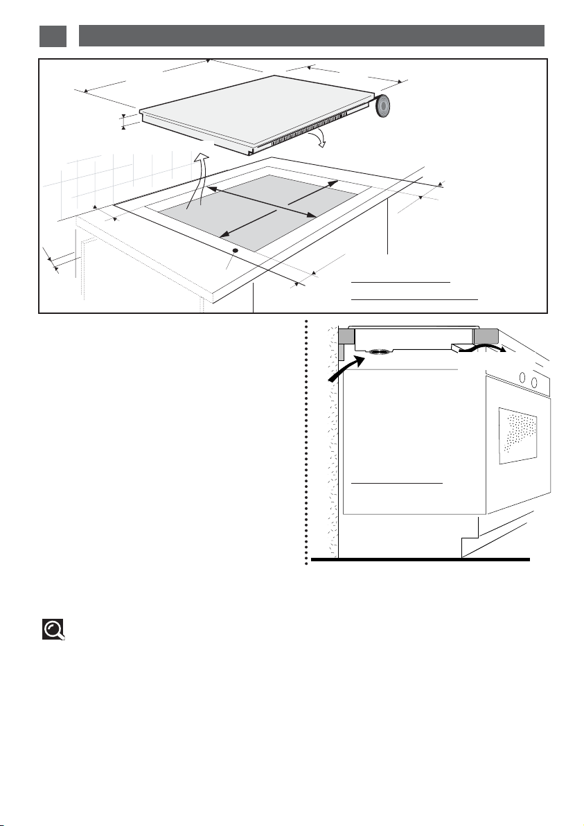
CHOOSING THE POSITION
The distance between the edge of your appliance
and the side and rear walls (or partitions) must be at
least four centimetres (zone A).
Your appliance may be built in without any restriction. Check, however, that the air intake and outlet
are free of obstruction.
The building-in method opposite is recommended
for use above an oven or a built-in appliance.
BUILDING-IN
Follow the diagram above.
Glue the foam seal underneath your appliance, following the perimeter of the hole in the worktop, upon
which your appliance will rest. This will ensure a
good seal against the worktop.
Attach the clips to the hob
(depending on the
model
).
ventilation space
l
•
L
l’
L’
6,4
Above an oven
MIN 4 mm
Above a cabinet
with a door or drawer
Tip
If your hob is located above your oven, the hob’s thermal safety devices can impede the
simultaneous use of the hob and the oven’s pyrolysis program.
Your hob is equipped with an anti-overheating safety system.
This safety device can trigger, for example, when the hob is installed over an oven that is not sufficiently insulated. If this occurs, a series of small lines appears on the control panel. In such circumstances we recommend that you increase the hob’s ventilation by creating an opening in the
side of the cabinet, (8 x 5 cm), and/or installing an oven insulation kit available from the after-sales
(Ref . 75X1652)
You can also install your hob above a dishwasher.
In this case, your worktop must be at least 900mm high in order to ensure proper ventilation to
your hob and you could also fit the dishwasher insulation kit that is available from the After-Sales
Service (Ref. 77X7781).
Air outlet
Air intake
1 / INSTALLING YOUR APPLIANCE
Entrée d'air
4 cm
4 cm
A
Sortie d'air
4 cm
4 cm
Page 5
EN
5
1 / INSTALLING YOUR APPLIANCE
Your appliance should be positioned so that the mains switch is accessible.
These hobs must be connected to the mains using a socket in compliance with publication CEI
60083 or an all-pole circuit-breaker device in compliance with the installation rules in force.
When power is first supplied to your hob, or after an extended power cut, an indicator light will
appear on the control panel. This information will disappear after 30 seconds.
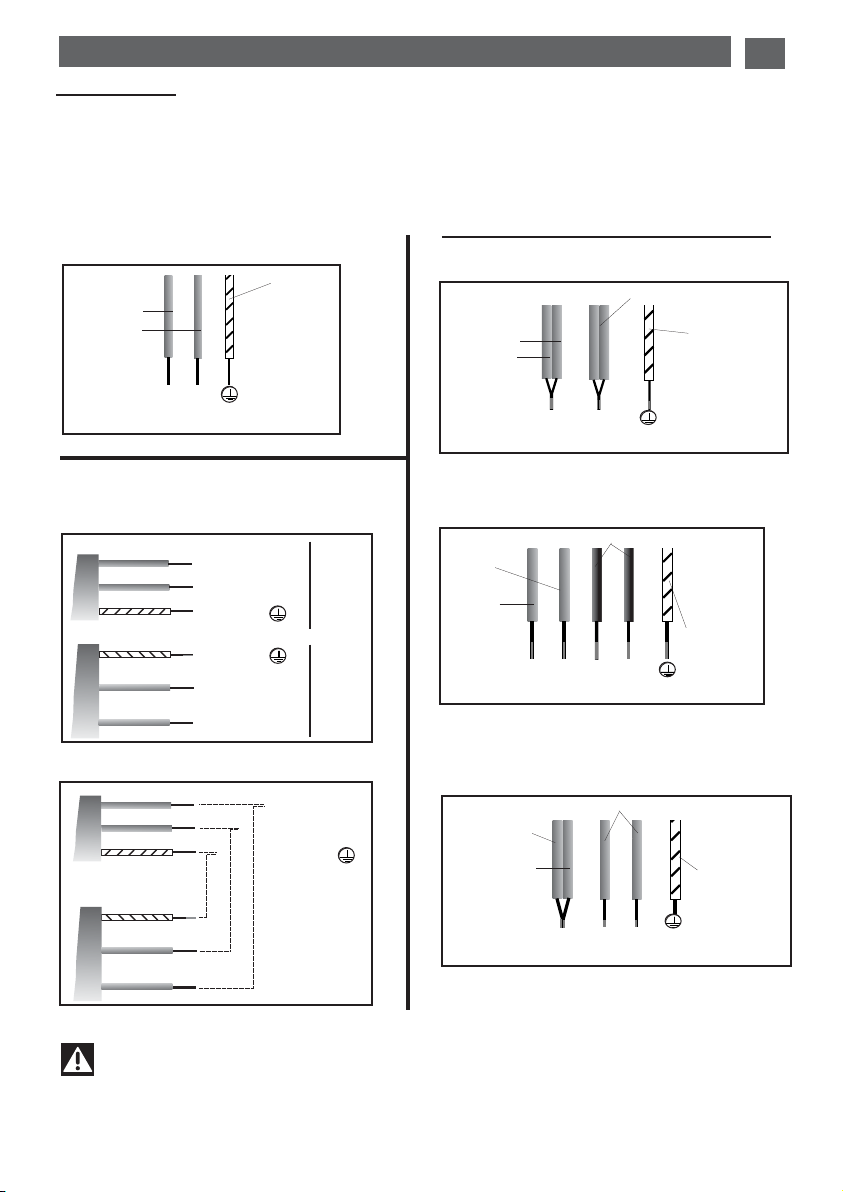
Connection
•
Hook-up of 220-240V
~
(DTI11177X -DTI1137X - DTI1047C et GC)
Warning
If the cable is damaged it must be replaced by the manufacturer, its after-sales serv-
ice or a person with a similar qualification to prevent danger.
N
L
Green/yellow
Blue
Brown
32A
Earth
Neutral
Phase
Neutral
Phase
N
L
Green/yellow
Blue
Brown
•
220-240 V monophase
hook-up(DTI1177X)
Earth
Bleu
Brown
Green/yellow
Earth
Phase
L
20 A
32 A
Green/yellow
Blue
Brown
Earth
Blue
Brown
Green/yellow
Neutral
N
Phase
L
32 amp fuses.
63 amp fuse.
Neutral
N
Separate the 2 phase wires L1 and L2 before
connection
N
L
Green/yellow
Blue
Black - grey
Brown
Neutral
Earth
Phase
N
L1
L2
Blue
Green/yellow
Black - grey
Brown
•
220-240V
~
With hook-up of 400 V 2N three phase, verify
that the neutral wie is properly connected
•
400V 2N
~
-
16A
32A
Separate the wires before connection
Neutral
Earth
Phase
N1
L1
L2
Blue
Green/yellow
Black - grey
Brown
•
2x230V 2L+2N
~
-
16A
N2
Earth
Neutral
Phase
Connection DTI1043XE - DTI1167XE
Page 6
EN
6
2 / USING YOUR APPLIANCE
•Choosing a cooking area
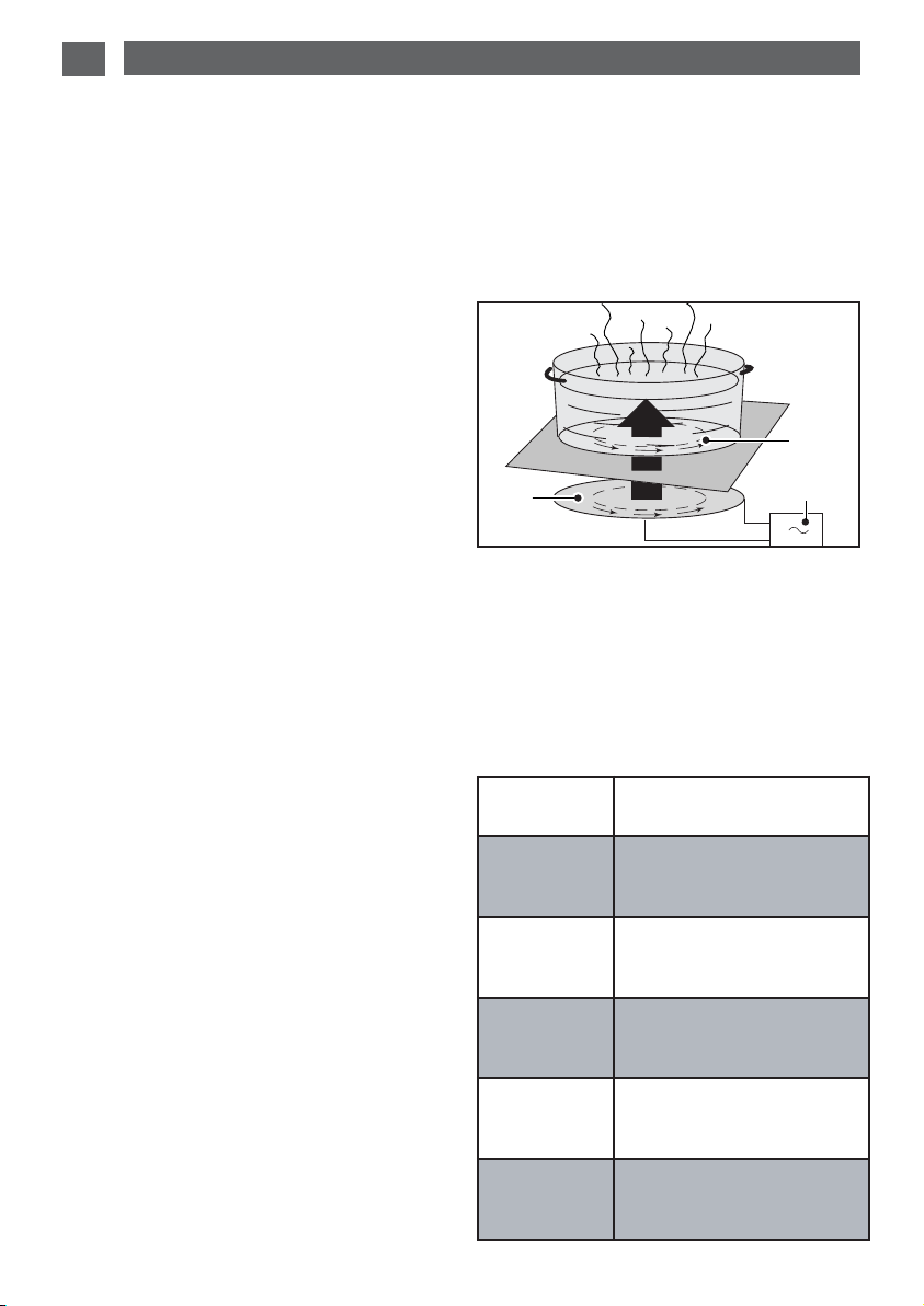
• The induction principle
The principle of induction is based on a magnetic effect.
When you place your cookware on a cooking
zone and you turn it on, the electronic circuits
in your cooking hob produce “induced” currents in the bottom of the cookware which
instantly raise its temperature. This heat is
then transmitted to the food
To help you choose, a list of cookware is provided with this guide.
We have designed this cooking hob for use by private individuals in their homes.
These cooking hobs are intended exclusively for cooking beverages and foodstuffs and do not
contain any asbestos-based materials.
This appliance is not intended to be used by persons (including children) with reduced physical, sensory or mental abilities, or persons lacking experience or awareness, unless using it with the help of
a person reponsible for their safety, or under supervision and with prior instruction in its use.
Children should be supervised to ensure that they do not play with the appliance.
C
B
A
• Cookware
Most cookware is compatible with induction.
To verify that your cookware is suitable, place
it on a heating area on power 4.
- If the display remains on, your cookware is
compatible.
- If the display flashes, your cookware cannot
be used with induction cooking.
You can also use a magnet to test the cookware.
If a magnet “sticks” to the bottom of the cookware, it is compatible with induction.
Only glass, terra cotta, aluminium without a
special finish on the bottom, copper and some
non-magnetic stainless steels do not work
with induction cooking. We recommend that
you select cookware with a thick, flat bottom.
A - Induction plate
B - Electronic circuit
C - Induced currents
Cooking
area
Diameter of base
of cookware
16 cm
10 ..... 18 cm
23 cm
12 ..... 26 cm
28 cm
12 .....32 cm
Front or rear
C
ONTINUUM
12 .....20 cm
Complete
C
ONTINUUM
18 ..... oval, fish kettle
+
-
Page 7

7
EN
2 / USING YOUR APPLIANCE
DTI1137X
28 cm
4600 W
Description of the top
Overall dimensions (L x l) DTI1137X : 65 x 51.3
Cut-out Recess (L’ x l’)
DTI1137X : 56 x 49
16 cm
2200 W
18 cm
2800 W
•
Selector buttons
Buttons A, B and C are used to select cooking
zones and turn them on and off. When a zone
is selected, you will see it light up, and you can
adjust its settings.
If there is no cookware on the selected zone, your adjustments will delete automatically after a
few moments.
Indicator for
selected zone
Power
display
Timer display
For a selected zone
B
A
C
•
Adjustment buttons
These buttons allow you to adjust power,
timer, programmer... for each of the selected
zones.
H
B
OIL
function
I power preselection
J recommended timer
K
E
LAPSEDTIME
function
L
locking - unlocking - Clean lock
M
S
WITCH
function
N
power slider
O timer slider
H
I
J
K
LM
N
O
00328
Page 8

EN
8
2 / USING YOUR APPLIANCE
DTI1117X
Overall dimensions (L x l) DTI1117X : 65 x 51.3
Cut-out Recess (L’ x l’)
DTI1117X : 56 x 49
18 cm
2800 W
22 cm
4000 W
16 cm
2200 W
18 cm
2800 W
•
Adjustment buttons
These buttons allow you to adjust power,
timer, programmer... for each of the selected
zones.
H
B
OIL
function
I power preselection
J recommended timer
K
E
LAPSEDTIME
function
L
locking - unlocking - Clean lock
M
S
WITCH
function
N
power slider
O timer slider
If there is no cookware on the selected zone, your adjustments will delete automatically after a
few moments.
B
A
C
D
•
Selector buttons
Buttons A, B and C are used to select cooking
zones and turn them on and off. When a zone
is selected, you will see it light up, and you can
adjust its settings.
Indicator for
selected zone
Power
display
Timer display
For a selected zone
H
I
J
K
LM
N
O
00310
Page 9

9
EN
2 / USING YOUR APPLIANCE
DTI1047GC - DTI1167XE
Overall dimensions (L x l) DTI1047C - DTI1047GC : 65 x 51
DTI1167XE : 78.2 x 50.7
Cut-out Recess (L’ x l’)
DTI1047C - DTI1047GC : 56 x 49
DTI1167XE : 75x49.6
For DTI1167XE
3600 W
23 cm
3100 W
16 cm
2200 W
For DTI1047C et GC
4600 W
If there is no cookware on the selected zone, your adjustments will delete automatically after a
few moments.
•
Adjustment buttons
These buttons allow you to adjust power,
timer, programmer... for each of the selected
zones.
H
B
OIL
function
I power preselection
J recommended timer
K
E
LAPSEDTIME
function
L
locking - unlocking - Clean lock
M
S
WITCH
function
N
power slider
O timer slider
•
Selector buttons
Use these buttons to select, turn on and turn
off the cooking zones. When a zone is selected, you will see it light up, and you can adjust
its settings.
A front C
ONTINUUM zone
B rear Continuum zone
C complete C
ONTINUUM zone
E 16 cm zone.
F zone 23 cm.
Indicator for
selected zone
Power
display
Timer display
For a selected zone
B
A
C
F
E
H
I
J
K
LM
N
O
00325
Page 10

EN
10
2 / USING YOUR APPLIANCE
•
Adjustment buttons
These buttons allow you to adjust power,
timer, programmer... for each of the selected
zones.
H
B
OIL
function
I power preselection
J recommended timer
K
E
LAPSEDTIME
function
L
locking - unlocking - Clean lock
M
S
WITCH
function
N
power slider
O timer slider
If there is no cookware on the selected zone, your adjustments will delete automatically after a
few moments.
DTI1177X
Overall dimensions (L x l) DTI1117X : 93 x 51
Cut-out Recess (L’ x l’)
DTI1117X : 90 x 49
4600 W
23 cm
3100 W
16 cm
2200 W
28 cm
4600 W
B
A
C
F
E
D
•
Selector buttons
Use these buttons to select, turn on and turn
off the cooking zones. When a zone is selected, you will see it light up, and you can adjust
its settings.
A front C
ONTINUUM zone
B rear C
ONTINUUM zone
C complete C
ONTINUUM zone
D 28 cm zone.
E 23 cm zone.
F 16 cm zone.
Indicator for
selected zone
Power
display
Timer display
For a selected zone
H
I
J
K
LM
N
O
00327
Page 11

EN
11
-
Briefly press button H to confirm
. A short beep
is heard and the ”boil” display becomes fixed.
A series of beeps are heard when your water is
at boiling point and the word “boil” scrolls
across the display (b followed by o etc...)
- Put the food in (pasta, rice, etc.)
Briefly press button “H”, power level 12 or 13
and 8 min are displayed by default.
You can change the power and time using
sliders N and O.
NB: It is important that the water temperature is
neither too hot nor too cold when cooking
begins otherwise the final result will be affected.
This function can be used on all burners at the
same time.
Do not use cast iron cookware.
Do not use a lid.
Do not use salt.
• Independent timer
This function allows you to time an event,
without cooking.
- Select a cooking zone you are not using.
- Set the time with the timer slider. A “t”
flashes in the display.
- At the end of your adjustment “t” becomes
steady and the count begins.
N.B.:
You can stop a count in progress by keeping
your finger on the button of the selection on
the display.
Using a cooking zone
Adjusting the power level:
- Place your cookware on the cooking zone
and press the on/off button for the zone to
be used. A beep and a light will confirm your
selection.
- Adjust the power by sliding your finger on
the power slider to the right to increase and
to the left to decrease the power or by using
the preselected power settings.
Switching off a cooking zone
- Press your finger on the selector button
Adjusting the timer:
- Adjust the timer by sliding your finger on the
timer slider to the right to increase and to
the left to decrease the time.
- When the cooking is finished, “0” is displayed and a beep sounds. Press on the
selector button for the zone to delete this
information.
N.B.:
- If you slide your finger on the timer slider
from right to left you to reach directly 99
minutes.
- If you do not make a selection or if there is
no cookware, the selected zone turns off
after a few moments.
ADDITIONAL FUNCTIONS
• Boil function
This function allows you to bring water to
boiling point and keep it there for any food
requiring cooking in boiling water.
-
Select a cooking zone.
-
Press button H briefly. A short beep is
heard. ”2l” is displayed by default.
-
Adjust the volume of water by sliding your finger on the power slider from 0.5 litres to 6 litres.
The quantity of water can be 0.5l, 1l ,1.5l, 2l,
2.5l, 3l, 4l, 5l and 6 litres.
B
A
C
D
H
I
J
K
LM
N
O
2 / USING YOUR APPLIANCE
Page 12

12
EN
2 / USING YOUR APPLIANCE
• Elapsed time
This function displays the time elapsed since
the last time the power setting was adjusted
on a given burner.
To use this function, press the K button. The
elapsed time flashes on the timer display.
If you want cooking to end in a specific period,
press the K button then, within 5 seconds,
slide your finger on the timer slider to increase
the cooking time that you wish to set. The time
will display for 3 seconds, then the remaining
cooking time will appear. A beep will confirm
your choice.
This function can be used with or without
the timer.
Note: If a time is displayed on the timer, it
cannot be changed for 5 seconds after
pressing the K button. Once this period has
elapsed, you may change your cooking time.
• SWITCH
This function lets you move a pan from one
zone to another, keeping the original settings
(power level and time).
1- Press button M briefly. A short beep
sounds and you can move the pan to the
new zone.
2- Press button M briefly. The information is
displayed on the new burner. The original
cooking zone switches off when the settings are displayed on the new zone.
- If there is no pan present before button M is
pressed, a long beep sounds and the function
is cancelled.
- If button M is pressed and more than one
pan is moved, the function is cancelled and
NO appears in the display.
- For models DTI1047C, DTI1047CG,
DTI1167XE and DTI1177X, if you move a pan
from one complete cooking zone to another
complete cooking zone, the function is cancelled and NO appears in the display.
- If the “Switch” function activates more than
one new zone, the function is cancelled and
NO appears in the display.
• Adjustment of power presets
This function allows you to change the power
levels defined in the presets (except for the
boost).
- Your cooking hob must be turned off.
- Select the preset I to be changed, by keeping your finger on it.
- Set the new power level by sliding your finger
over the power slider.
- A beep will confirm your action after a few
moments.
N.B.:
The power levels must be between:
- 1 and 5 for the first button (4 by default).
- 6 and 10 for the second (8 by default).
- 11 and 15 for the third (15 by default).
B
A
C
D
H
I
J
K
LM
N
O
Page 13

EN
13
2 / USING YOUR APPLIANCE
• Child safety
This function allows you to lock your hob when
it is shut off or when it is cooking.
To l o c k :
- Press button L until you hear a beep and the
indicator lights up. The indicator will go out
automatically after a few moments.
To unlock:
- Press button L until you hear a double beep
and the indicator goes out.
N.B.:
- In locked mode, any action will produce a key
symbol on the display. You must unlock your
hob before using it.
- If you activate the lock while cooking, the
stop display will be prioritised on the lock.
• Clean lock
This function allows you to temporarily lock
your hob while cleaning.
To activate Clean Lock:
- Your cooking hob must be turned off.
- Press button L briefly; you will hear a beep
and the indicator will start flashing.
- After a preset time, the lock will automatically
disengage. A double beep sounds and the
indicator goes out.
Page 14

14
EN
2 / USING YOUR APPLIANCE
Safety when operating
•Residual heat
After a long cooking period, the zone used
can remain hot for several minutes. An ‘’H’’
flashes during this period. Do not put your
hand on the zone.
•Temperature limiter
Each cooking zone is equipped with a safety
sensor that constantly monitors the temperature of the bottom of the cookware. If you
leave empty cookware on a zone which is
turned on, it will automatically limit the power
in order to prevent damage to the cookware
or hob.
• Protection against overflows
In case of overflow, or of a metallic object or
wet cloth placed on the control areas, the hob
turns itself off, the displays light up and a
beep sounds. Clean the hob or remove the
object, then begin cooking again.
•Auto-Stop system
If you forget cooking is in progress, after a
predefined time, this safety function will automatically turn off your hob (from 1 to 10 hours
depending on the power setting). “AS” displays and a beep sounds after about
2 minutes. Press on the main selector to
delete this information. A beep will confirm
your setting.
• “Small Items” safety
If you place a small object on the area (a ring,
a fork, etc), the hob will detect it and not deliver any power. The power display flashes.
Note:
However, several small objects at the same
time on a zone could be identified as cookware. In that case, power will be delivered by
the hob.
It is recommended that you avoid
placing metal objects such as knives,
forks, spoons and lids on the cooking surface, as they may become hot.
•For users with heart pacemakers and active implants.
The functioning of the hob conforms to current electromagnetic interference standards and thus
is in total compliance with legal requirements (89/336/EEC directives).
In order to avoid interference between your cooking hob and a pacemaker, your pacemaker
must be designed and programmed in compliance with the regulations that apply to it.
As we can guarantee the compliance only of our own products, we strongly recommend that
you refer to the maker of your device or to your doctor to avoid possible incompatibilities.
As shown in this logo, the materials used to package this appliance are not recyclable. Recycle them and play a role in protecting the environment by depositing them
in municipal containers provided for this purpose.
Recycling of the appliances organised by your manufacturer will thus be undertaken
in optimum conditions, in accordance with European directive 2002/96/CE relating
to electrical and electronic equipment waste. Contact your local authority or retailer
for how to have used appliances collected or collection points.
Page 15

15
3 / MAINTAINING YOUR APPLIANCE EN
Preserve your appliance
The vitroceramic glass surface is highly
resistant, but not unbreakable. Here are some
recommendations for increasing its lifetime:
- Avoid banging or clattering the cookware.
- Avoid putting heating covers on the hob. A
suction effect may damage the vitroceramic
surface.
- Do not use cookware with bottoms that are
rough or dented.
- Do not use your cooking hob as a work surface.
- Never use aluminium foil or paper or aluminium scrubber to clean it. The aluminium
melts and damages the top.
- Never use a steam cleaner to clean your
hob.
Maintaining your appliance
- Never directly reheat a tin can. It will have a
risk of exploding.
Aesthetic faults, as a result of mistreatment of
your hob and which do not entail a lack of
function, are not covered by our guarantee.
And for the safety of your kitchen, do not
place cleaning items or inflammable objects
or products in the kitchen furniture underneath your cooking hob.
TYPES OF STAINS/SPOTS
Light.
Accumulation of baked-on
stains/dirt.
Sugar spills, melted plastics.
Rings and hard water
residue.
Shiny metal colourings.
Weekly maintenance.
WHAT TO DO?
Thoroughly moisten the zone to be
cleaned with hot water, then wipe off.
Thoroughly moisten the zone to be
cleaned with hot water. Use a scraper for
glass to remove the large bits, follow with
the rough side of a disinfectant sponge,
and then wipe off.
Apply warm white vinegar to the stain, let
stand, then wipe with a soft cloth.
Apply a cleaning agent for vitroceramic
glass (preferable one with silicon for its
protective properties) to the surface.
USE
Cleaning sponges
Cleaning sponges
Scraper for glass.
White vinegar.
Special vitroceramic glass product.
cream
cleaning sponge
special for delicate crockery
abrasive sponge
powder
Page 16

16
EN
4 / SPECIAL MESSAGES, DIFFICULTIES
In case of breakage, cracks or even light fissures in the vitroceramic glass, take out
the fuses or turn off the circuit breaker for your hob to avoid the risk of electrical
shock.
Contact the After-Sales Service Department.
The hob does not operate and
the indicator lights on the control panel do not light up.
The hob is not working and
another message is displayed.
The hob does not function, the
information is displayed.
The machine is not connected to
the power source. The power
source or connection is defective.
The electronic board is functioning poorly.
The hob is locked
Inspect the electrical circuit breaker and fuses.
Call the After-Sales
Service Department.
See chapter on using the
child safety system
The hob has stopped operating
and is beeping approximately
every 10 seconds and a or
F7 is displayed.
A series of small or F7 is
displayed.
After turning on a heating zone,
the indicator lights on the control panel continue to flash.
The saucepans make noise during cooking.
Your hob makes a clicking
sound during cooking.
The fan continues to function a
few minutes after your hob is
turned off.
There was an overflow or an
object is in contact with the
control panel.
The electronic circuits have
overheated.
The cookware used is not suitable for induction or is less than
12 cm in diameter (10 cm on a
16 cm area).
This is normal with some types
of cookware. This is caused by
the transfer of energy from the
hob to the cookware.
Cooling of the electronic components.
Working normally.
Clean the hob or remove
the object, then begin
cooking again.
See “Inserting” section.
See section on cookware
for induction.
Nothing. There is no risk,
neither to your hob nor to
your cookware.
Nothing.
•While in use
•On switching on
YOU OBSERVE THAT: POSSIBLE CAUSES:
WHAT SHOULD YOU DO?
YOU OBSERVE THAT: POSSIBLE CAUSES:
WHAT SHOULD YOU DO?
POSSIBLE CAUSES:
WHAT SHOULD YOU DO?
A special lamp appears.
Your installation blows a fuse.
Only one side works.
The hob produces an odour during the first cooking sessions.
Working normally.
The electrical connection of
your hob is incorrect.
New appliance.
Nothing, the light disappears
after 30 seconds.
Check that it is set up
properly.
See the “Electrical
Connection” section.
Nothing. The smell will disappear after several uses.
•On first use
Page 17

17
1.Subject to the "Statement of Standard
Warranty Conditions" this product is covered
by the following Warranty.
TWO (2) YEARS WARRANTY from date of
purchase, covering all parts and labour.
2.The appliance is warranted under normal
single family domestic installation and use,
as set out in the user manual, against manufacturing defects for the Warranty periods
shown above.
3.Should service be required under this
Warranty, the purchaser should contact an
approved DE DIETRICH Service Provider
during their normal business hours.
4.At no time does DE DIETRICH have liability
for any freight or transportation costs or for
any damage during transit or for any consequence of failure of this appliance outside of
the normal service area, unless such limitation of liability is prohibited by statute.
5.This Warranty excludes replacement of
parts required due to normal wear and tear
including light globes.
6.This Warranty only applies, provided the
appliance has been used in accordance with
the manufacturer's instructions and provided
an accident, misuse, neglect or abuse has
not damaged the appliance.
7.None of the above Warranties purport to
exclude, restrict or modify either the application or the exercise of a right conferred by
any applicable Statute.
8.Please complete the details below, which
should be retained for future reference along
with your proof of purchase:
Date of Purchase: ……………………………..
Model No: ……………………………………….
Serial No: ………………………………………..
Notice to Victorian Customers from the Victorian
Plumbing Industry Commission.
This product must be installed by a licensed person as
required by the Victorian Building Act 1993.
Only a licensed person will give you a Compliance
Certificate, showing that the work complies with all the
relevant standards. Only a licensed person will have insurance protecting their workmanship for 6 years. Make sure
you use a licensed person to install this product and ask
for your Compliance Certificate.
1. The Warranty only applies provided that
the appliance has been used in accordance
with the manufacturer's instructions and provided that the appliance has not been damaged by an accident, misuse, neglect or abuse
of any person other than the manufacturer or
MEA or from faulty installation, mis-adjustment or tampering by unauthorised persons.
2. When a service inspection reveals the alleged fault or faults are caused by incorrect
operation, contrary to the instruction manual,
and otherwise the appliance is in good order
and working condition, the purchaser shall
be liable for a service fee charged by MEA or
one of its' Service Providers.
3. If the appliance is used in Commercial
Applications or for Rental purposes, a separate warranty of Twelve (12) months covering
all parts with Three (3) months on the labour
will apply.
4. Subject to the provisions of any applicable
statute this Warranty applies to the original
retail purchaser only and is not transferable.
5. Subject to the provisions of any applicable
statute, at no time does MEA have liability for
freight, transport or travel costs outside normal service areas.
6. None of the above Warranties purport to
exclude, restrict or modify either the application or the exercise of a right conferred by
any applicable statute.
7. Subject to any Warranties implied by statute, at no time will MEA or its' Service
Providers be liable for any economic loss
consequent upon the failure of the appliance.
8. This Warranty is only valid for De Dietrich
major appliances imported and distributed by
MEA, purchased and used in Australia.
PRODUCT WARRANTY
Distributed by MEA (A Divisions of Hagemeyer Brands Australia)
FOR AUSTRALIAN CUSTOMERS ONLY
STATEMENT OF STANDARD
WARRANTY CONDITIONS
CZ5701486 /00 07/12
 Loading...