

Page 1
ELITEC
Low temperature gas boiler
DTG 130 Eco.NOx
EN
Installation and
Service Manual
300002915-001-E
Page 2
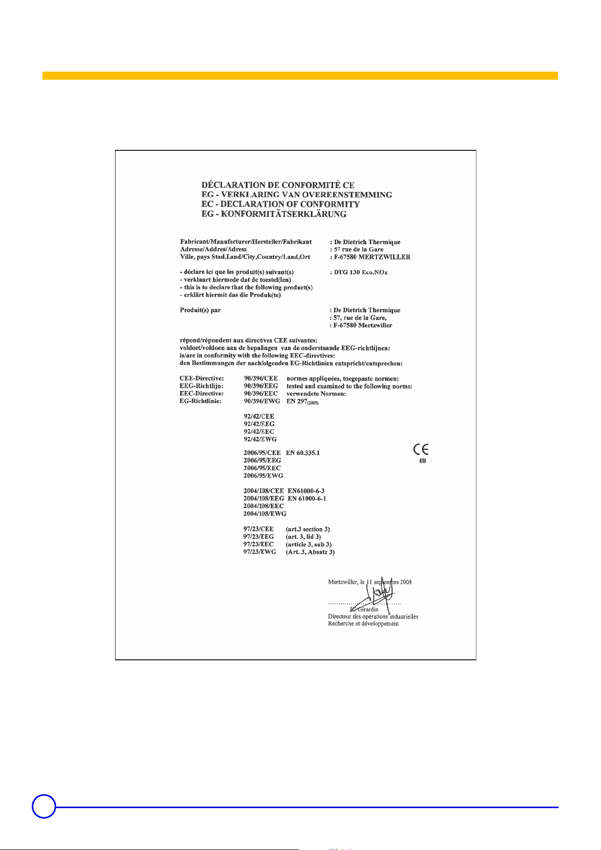
Declaration of conformity 1
The appliance complies with the standard model described in declaration of compliance 1. It is manufactured and distributed pursuant to the
requirements of european directives. The original of the declaration of compliance is available from the manufacturer.
L000148-A
2
DTG 130 Eco.NOx 01/02/11 - 300002915-001-E
Page 3

Contents
1 Introduction . . . . . . . . . . . . . . . . . . . . . . . . . . . . . . . . . . . . . . . . . . . . . . . . . . . . . . . . . . . . . . . . . . . . . . . . . . . . .5
1.1 Used symbols . . . . . . . . . . . . . . . . . . . . . . . . . . . . . . . . . . . . . . . . . . . . . . . . . . . . . . . . . . . . . . . . . . . . . . . . . . . . . . . . . . . . . . . . . . .5
1.2 General. . . . . . . . . . . . . . . . . . . . . . . . . . . . . . . . . . . . . . . . . . . . . . . . . . . . . . . . . . . . . . . . . . . . . . . . . . . . . . . . . . . . . . . . . . . . . . . .5
1.3 Homologations . . . . . . . . . . . . . . . . . . . . . . . . . . . . . . . . . . . . . . . . . . . . . . . . . . . . . . . . . . . . . . . . . . . . . . . . . . . . . . . . . . . . . . . . . .6
1.3.1 User country. . . . . . . . . . . . . . . . . . . . . . . . . . . . . . . . . . . . . . . . . . . . . . . . . . . . . . . . . . . . . . . . . . . . . . . . . . . . . . . . . . . . . .7
1.3.2 Directive 97/23/EC . . . . . . . . . . . . . . . . . . . . . . . . . . . . . . . . . . . . . . . . . . . . . . . . . . . . . . . . . . . . . . . . . . . . . . . . . . . . . . . . .7
2 Safety instructions and recommendations. . . . . . . . . . . . . . . . . . . . . . . . . . . . . . . . . . . . . . . . . . . . . . . . . . . .8
2.1 Safety instructions . . . . . . . . . . . . . . . . . . . . . . . . . . . . . . . . . . . . . . . . . . . . . . . . . . . . . . . . . . . . . . . . . . . . . . . . . . . . . . . . . . . . . . .8
2.2 Recommendations . . . . . . . . . . . . . . . . . . . . . . . . . . . . . . . . . . . . . . . . . . . . . . . . . . . . . . . . . . . . . . . . . . . . . . . . . . . . . . . . . . . . . . .8
3 Technical description . . . . . . . . . . . . . . . . . . . . . . . . . . . . . . . . . . . . . . . . . . . . . . . . . . . . . . . . . . . . . . . . . . . . .9
3.1 General description . . . . . . . . . . . . . . . . . . . . . . . . . . . . . . . . . . . . . . . . . . . . . . . . . . . . . . . . . . . . . . . . . . . . . . . . . . . . . . . . . . . . . .9
3.2 Technical characteristics . . . . . . . . . . . . . . . . . . . . . . . . . . . . . . . . . . . . . . . . . . . . . . . . . . . . . . . . . . . . . . . . . . . . . . . . . . . . . . . . .10
3.3 Main parts. . . . . . . . . . . . . . . . . . . . . . . . . . . . . . . . . . . . . . . . . . . . . . . . . . . . . . . . . . . . . . . . . . . . . . . . . . . . . . . . . . . . . . . . . . . . .11
3.4 Operating principle . . . . . . . . . . . . . . . . . . . . . . . . . . . . . . . . . . . . . . . . . . . . . . . . . . . . . . . . . . . . . . . . . . . . . . . . . . . . . . . . . . . . . .12
4 Installation . . . . . . . . . . . . . . . . . . . . . . . . . . . . . . . . . . . . . . . . . . . . . . . . . . . . . . . . . . . . . . . . . . . . . . . . . . . . .14
4.1 Regulations governing installation . . . . . . . . . . . . . . . . . . . . . . . . . . . . . . . . . . . . . . . . . . . . . . . . . . . . . . . . . . . . . . . . . . . . . . . . . .14
4.1.1 France . . . . . . . . . . . . . . . . . . . . . . . . . . . . . . . . . . . . . . . . . . . . . . . . . . . . . . . . . . . . . . . . . . . . . . . . . . . . . . . . . . . . . . . . .14
4.1.2 Germany . . . . . . . . . . . . . . . . . . . . . . . . . . . . . . . . . . . . . . . . . . . . . . . . . . . . . . . . . . . . . . . . . . . . . . . . . . . . . . . . . . . . . . .14
4.1.3 Switzerland. . . . . . . . . . . . . . . . . . . . . . . . . . . . . . . . . . . . . . . . . . . . . . . . . . . . . . . . . . . . . . . . . . . . . . . . . . . . . . . . . . . . . .15
4.1.4 Other countries. . . . . . . . . . . . . . . . . . . . . . . . . . . . . . . . . . . . . . . . . . . . . . . . . . . . . . . . . . . . . . . . . . . . . . . . . . . . . . . . . . .15
4.2 Package list . . . . . . . . . . . . . . . . . . . . . . . . . . . . . . . . . . . . . . . . . . . . . . . . . . . . . . . . . . . . . . . . . . . . . . . . . . . . . . . . . . . . . . . . . . .15
4.3 Mounting. . . . . . . . . . . . . . . . . . . . . . . . . . . . . . . . . . . . . . . . . . . . . . . . . . . . . . . . . . . . . . . . . . . . . . . . . . . . . . . . . . . . . . . . . . . . . .16
4.3.1 Position of the boiler. . . . . . . . . . . . . . . . . . . . . . . . . . . . . . . . . . . . . . . . . . . . . . . . . . . . . . . . . . . . . . . . . . . . . . . . . . . . . . .16
4.3.2 Ventilation . . . . . . . . . . . . . . . . . . . . . . . . . . . . . . . . . . . . . . . . . . . . . . . . . . . . . . . . . . . . . . . . . . . . . . . . . . . . . . . . . . . . . .16
4.3.3 Main dimensions . . . . . . . . . . . . . . . . . . . . . . . . . . . . . . . . . . . . . . . . . . . . . . . . . . . . . . . . . . . . . . . . . . . . . . . . . . . . . . . . .17
4.3.4 Assembling the appliance . . . . . . . . . . . . . . . . . . . . . . . . . . . . . . . . . . . . . . . . . . . . . . . . . . . . . . . . . . . . . . . . . . . . . . . . . .19
4.3.5 Levelling . . . . . . . . . . . . . . . . . . . . . . . . . . . . . . . . . . . . . . . . . . . . . . . . . . . . . . . . . . . . . . . . . . . . . . . . . . . . . . . . . . . . . . . .20
4.4 Hydraulic connections . . . . . . . . . . . . . . . . . . . . . . . . . . . . . . . . . . . . . . . . . . . . . . . . . . . . . . . . . . . . . . . . . . . . . . . . . . . . . . . . . . .21
4.4.1 Regulations . . . . . . . . . . . . . . . . . . . . . . . . . . . . . . . . . . . . . . . . . . . . . . . . . . . . . . . . . . . . . . . . . . . . . . . . . . . . . . . . . . . . .21
4.4.2 Hydraulic connection of the heating circuit. . . . . . . . . . . . . . . . . . . . . . . . . . . . . . . . . . . . . . . . . . . . . . . . . . . . . . . . . . . . . .21
4.4.3 Hydraulic connection of the water circuit for domestic use . . . . . . . . . . . . . . . . . . . . . . . . . . . . . . . . . . . . . . . . . . . . . . . . .21
4.4.4 Filling the system . . . . . . . . . . . . . . . . . . . . . . . . . . . . . . . . . . . . . . . . . . . . . . . . . . . . . . . . . . . . . . . . . . . . . . . . . . . . . . . . .22
4.4.5 Water treatment . . . . . . . . . . . . . . . . . . . . . . . . . . . . . . . . . . . . . . . . . . . . . . . . . . . . . . . . . . . . . . . . . . . . . . . . . . . . . . . . . .22
4.5 Gas connection. . . . . . . . . . . . . . . . . . . . . . . . . . . . . . . . . . . . . . . . . . . . . . . . . . . . . . . . . . . . . . . . . . . . . . . . . . . . . . . . . . . . . . . . .22
4.6 Connection to a chimney . . . . . . . . . . . . . . . . . . . . . . . . . . . . . . . . . . . . . . . . . . . . . . . . . . . . . . . . . . . . . . . . . . . . . . . . . . . . . . . . .23
4.7 Electrical connections. . . . . . . . . . . . . . . . . . . . . . . . . . . . . . . . . . . . . . . . . . . . . . . . . . . . . . . . . . . . . . . . . . . . . . . . . . . . . . . . . . . .23
4.8 Skeleton Diagrams . . . . . . . . . . . . . . . . . . . . . . . . . . . . . . . . . . . . . . . . . . . . . . . . . . . . . . . . . . . . . . . . . . . . . . . . . . . . . . . . . . . . . .23
5 Commissioning . . . . . . . . . . . . . . . . . . . . . . . . . . . . . . . . . . . . . . . . . . . . . . . . . . . . . . . . . . . . . . . . . . . . . . . . .24
5.1 Control panel . . . . . . . . . . . . . . . . . . . . . . . . . . . . . . . . . . . . . . . . . . . . . . . . . . . . . . . . . . . . . . . . . . . . . . . . . . . . . . . . . . . . . . . . . .24
5.2 Check points before commissioning. . . . . . . . . . . . . . . . . . . . . . . . . . . . . . . . . . . . . . . . . . . . . . . . . . . . . . . . . . . . . . . . . . . . . . . . .24
5.3 Commissioning procedure . . . . . . . . . . . . . . . . . . . . . . . . . . . . . . . . . . . . . . . . . . . . . . . . . . . . . . . . . . . . . . . . . . . . . . . . . . . . . . . .24
5.4 Gas settings . . . . . . . . . . . . . . . . . . . . . . . . . . . . . . . . . . . . . . . . . . . . . . . . . . . . . . . . . . . . . . . . . . . . . . . . . . . . . . . . . . . . . . . . . . .25
5.4.1 Changing the burner injectors . . . . . . . . . . . . . . . . . . . . . . . . . . . . . . . . . . . . . . . . . . . . . . . . . . . . . . . . . . . . . . . . . . . . . . .25
5.4.2 Changing the ignition burner injector . . . . . . . . . . . . . . . . . . . . . . . . . . . . . . . . . . . . . . . . . . . . . . . . . . . . . . . . . . . . . . . . . .25
5.4.3 Setting the injector pressure . . . . . . . . . . . . . . . . . . . . . . . . . . . . . . . . . . . . . . . . . . . . . . . . . . . . . . . . . . . . . . . . . . . . . . . .26
5.4.4 Setting the start up pressure . . . . . . . . . . . . . . . . . . . . . . . . . . . . . . . . . . . . . . . . . . . . . . . . . . . . . . . . . . . . . . . . . . . . . . . .26
5.4.5 Attaching the label . . . . . . . . . . . . . . . . . . . . . . . . . . . . . . . . . . . . . . . . . . . . . . . . . . . . . . . . . . . . . . . . . . . . . . . . . . . . . . . .27
5.4.6 Pressure setting and marking of calibrated injectors . . . . . . . . . . . . . . . . . . . . . . . . . . . . . . . . . . . . . . . . . . . . . . . . . . . . . .27
5.5 Checks and adjustments after commissioning . . . . . . . . . . . . . . . . . . . . . . . . . . . . . . . . . . . . . . . . . . . . . . . . . . . . . . . . . . . . . . . . .27
5.6 Changing the settings. . . . . . . . . . . . . . . . . . . . . . . . . . . . . . . . . . . . . . . . . . . . . . . . . . . . . . . . . . . . . . . . . . . . . . . . . . . . . . . . . . . .27
01/02/11 - 300002915-001-E DTG 130 Eco.NOx
3
Page 4

6 Switching off the boiler. . . . . . . . . . . . . . . . . . . . . . . . . . . . . . . . . . . . . . . . . . . . . . . . . . . . . . . . . . . . . . . . . . .28
6.1 Precautions to take if there is a danger of frost . . . . . . . . . . . . . . . . . . . . . . . . . . . . . . . . . . . . . . . . . . . . . . . . . . . . . . . . . . . . . . . .28
6.2 Precautions to take in the event of prolonged shutdown (one year or more) . . . . . . . . . . . . . . . . . . . . . . . . . . . . . . . . . . . . . . . . . .28
7 Checking and maintenance . . . . . . . . . . . . . . . . . . . . . . . . . . . . . . . . . . . . . . . . . . . . . . . . . . . . . . . . . . . . . . .29
7.1 Checks . . . . . . . . . . . . . . . . . . . . . . . . . . . . . . . . . . . . . . . . . . . . . . . . . . . . . . . . . . . . . . . . . . . . . . . . . . . . . . . . . . . . . . . . . . . . . . .29
7.1.1 Water level . . . . . . . . . . . . . . . . . . . . . . . . . . . . . . . . . . . . . . . . . . . . . . . . . . . . . . . . . . . . . . . . . . . . . . . . . . . . . . . . . . . . . .29
7.1.2 Safety devices . . . . . . . . . . . . . . . . . . . . . . . . . . . . . . . . . . . . . . . . . . . . . . . . . . . . . . . . . . . . . . . . . . . . . . . . . . . . . . . . . . .29
7.1.3 Checking the ignition burner . . . . . . . . . . . . . . . . . . . . . . . . . . . . . . . . . . . . . . . . . . . . . . . . . . . . . . . . . . . . . . . . . . . . . . . .29
7.1.4 Checking pressure to the nozzle . . . . . . . . . . . . . . . . . . . . . . . . . . . . . . . . . . . . . . . . . . . . . . . . . . . . . . . . . . . . . . . . . . . . .30
7.1.5 Checking burner safety . . . . . . . . . . . . . . . . . . . . . . . . . . . . . . . . . . . . . . . . . . . . . . . . . . . . . . . . . . . . . . . . . . . . . . . . . . . .30
7.1.6 Checking the safety thermostat . . . . . . . . . . . . . . . . . . . . . . . . . . . . . . . . . . . . . . . . . . . . . . . . . . . . . . . . . . . . . . . . . . . . . .30
7.1.7 Checking the downdraught thermostat . . . . . . . . . . . . . . . . . . . . . . . . . . . . . . . . . . . . . . . . . . . . . . . . . . . . . . . . . . . . . . . .30
7.2 Maintenance . . . . . . . . . . . . . . . . . . . . . . . . . . . . . . . . . . . . . . . . . . . . . . . . . . . . . . . . . . . . . . . . . . . . . . . . . . . . . . . . . . . . . . . . . . .31
7.2.1 Cleaning main burner and ignition burner . . . . . . . . . . . . . . . . . . . . . . . . . . . . . . . . . . . . . . . . . . . . . . . . . . . . . . . . . . . . . .31
7.2.2 Cleaning of the heating body . . . . . . . . . . . . . . . . . . . . . . . . . . . . . . . . . . . . . . . . . . . . . . . . . . . . . . . . . . . . . . . . . . . . . . . .32
7.2.3 Cleaning painted surfaces . . . . . . . . . . . . . . . . . . . . . . . . . . . . . . . . . . . . . . . . . . . . . . . . . . . . . . . . . . . . . . . . . . . . . . . . . .32
7.3 Troubleshooting . . . . . . . . . . . . . . . . . . . . . . . . . . . . . . . . . . . . . . . . . . . . . . . . . . . . . . . . . . . . . . . . . . . . . . . . . . . . . . . . . . . . . . . .33
7.3.1 Error messages . . . . . . . . . . . . . . . . . . . . . . . . . . . . . . . . . . . . . . . . . . . . . . . . . . . . . . . . . . . . . . . . . . . . . . . . . . . . . . . . . .33
7.3.2 Incidents and solutions. . . . . . . . . . . . . . . . . . . . . . . . . . . . . . . . . . . . . . . . . . . . . . . . . . . . . . . . . . . . . . . . . . . . . . . . . . . . .33
8 Spare parts - DTG 130 Eco.NOx . . . . . . . . . . . . . . . . . . . . . . . . . . . . . . . . . . . . . . . . . . . . . . . . . . . . . . . . . . . .35
8.1 Boiler body + Draught diverter + Insulation . . . . . . . . . . . . . . . . . . . . . . . . . . . . . . . . . . . . . . . . . . . . . . . . . . . . . . . . . . . . . . . . . . .35
8.2 Gas line + Conversion set . . . . . . . . . . . . . . . . . . . . . . . . . . . . . . . . . . . . . . . . . . . . . . . . . . . . . . . . . . . . . . . . . . . . . . . . . . . . . . . .36
8.2.1 3 sections . . . . . . . . . . . . . . . . . . . . . . . . . . . . . . . . . . . . . . . . . . . . . . . . . . . . . . . . . . . . . . . . . . . . . . . . . . . . . . . . . . . . . . .36
8.2.2 4-6 sections . . . . . . . . . . . . . . . . . . . . . . . . . . . . . . . . . . . . . . . . . . . . . . . . . . . . . . . . . . . . . . . . . . . . . . . . . . . . . . . . . . . . .36
8.2.3 7-9 sections . . . . . . . . . . . . . . . . . . . . . . . . . . . . . . . . . . . . . . . . . . . . . . . . . . . . . . . . . . . . . . . . . . . . . . . . . . . . . . . . . . . . .37
8.3 Casing . . . . . . . . . . . . . . . . . . . . . . . . . . . . . . . . . . . . . . . . . . . . . . . . . . . . . . . . . . . . . . . . . . . . . . . . . . . . . . . . . . . . . . . . . . . . . . .37
8.4 Control panels . . . . . . . . . . . . . . . . . . . . . . . . . . . . . . . . . . . . . . . . . . . . . . . . . . . . . . . . . . . . . . . . . . . . . . . . . . . . . . . . . . . . . . . . .37
4
DTG 130 Eco.NOx 01/02/11 - 300002915-001-E
Page 5

1Introduction
1.1 Used symbols
Caution danger
Risk of injury and damage to equipment. Attention must be
paid to the warnings on safety of persons and equipment.
Specific information
Information must be kept in mind to maintain comfort.
1.2 General
Congratulations on your choice of a high quality product. We
strongly advise you to read the following instructions in order to
guarantee the optimal operation of your appliance. We are sure
that it will be entirely to your satisfaction and will meet with all
of your expectations.
` Keep these instructions in a safe place close to the appliance.
` For a proper operating of the boiler, follow carefully the
instructions.
Reference
Z
Refer to another manual or other pages in this instruction
manual.
DHW: Domestic hot water
` The manufacturer is not liable for any improper use of the
appliance or failure to maintain or install the unit correctly (the
user shall take care to ensure that the system is installed by a
qualified engineer).
` In the interest of customers, De Dietrich Thermique SAS are
continuously endeavouring to make improvements in product
quality. All the specifications stated in this document are
therefore subject to change without notice.
01/02/11 - 300002915-001-E DTG 130 Eco.NOx
5
Page 6
1.3 Homologations
CE identification no: CE-0085BP0002
Type B11
BS
boiler
France: Performance class III boiler according to ATG B 84
recommendations.
Thermal performance level (according to NFD 30-002): B300
Switzerland: Boilers are tested under the LRV-92 standard.
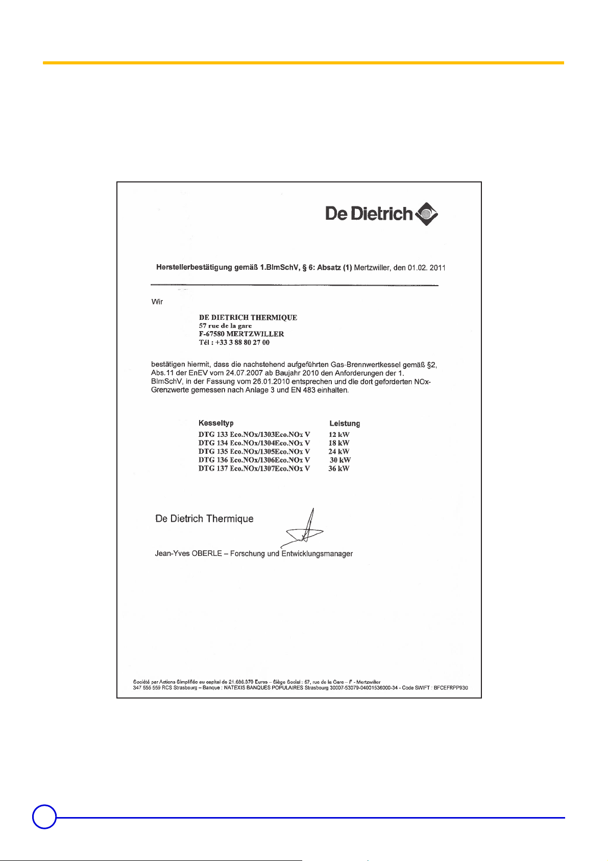
Germany:
DTG 130 EcoNox Boilers comply with the 1. BImSchV prescription,
version 2010.
L000147-A
6
DTG 130 Eco.NOx 01/02/11 - 300002915-001-E
Page 7
1.3.1 User country
User country
FR
ES, PT, IE, CH, GB, DK,
CZ, GR, SI, LT, SK
IT, SE, NO, FI, IS, EE,
TR, LV, BG
AT
DE
NL
LU
Gas
category
II
2ESi3P
II
2H3P
I
2H
II
2H3P
II
2ELL3P
II
2L3P
II
2E3P
Gas type
G20 20
G25 25
G31 37
G20 20
G31 30/37
G20 20
G20 20
G31 50
G20 20
G25 20
G31 50
G25 25
G31 50
G20 20
G25 20
G31 50
Connection
pressure (mbar)
User country
HU
RU, UA
PL
CY
Gas
category
II
2ES3P
I
2H
II
2ELwLs3P
I
3P
Gas type
G20 25
G25.1 25
G31 30/50
G20 20
G20 13
GZ50 20
GZ410 20
GZ350 13
G31 30/37
G31 30
Connection
pressure (mbar)
DTG 130 Eco.NOx boilers are delivered preset for operation on
natural gases of H/E groups.
For operation on another gas group, see the chapter "Gas
Z
settings" (Page: 25).
1.3.2 Directive 97/23/EC
Gas and oil boilers with a maximum operating temperature of 110°C
and hot water tanks with a maximum operating pressure of 10 bar
pertain to article 3.3 of the directive, and therefore, cannot be CEmarked to certify compliance with the directive 97/23 EC.
De Dietrich boilers and DHW tanks conform to the regulations in
article 3.3 of the 97/23/CEE Directive and is backed by the CE mark
for the 90/396/CEE, 92/42/CEE, 2006/95/EC and 2004/108/EC
directives.
01/02/11 - 300002915-001-E DTG 130 Eco.NOx
7
Page 8

2 Safety instructions and recommendations
2.1 Safety instructions
Fire hazard
Do not stock products of an inflammable nature close to
the appliance.
If you smell gas, do not use a naked flame, do not smoke,
do not operate electrical contacts or switches (doorbell,
lights, motor, lift, etc.).
1. Isolate the gas supply
2. Open the windows
3. Extinguish all flames
4. Evacuate the premises
5. Contact a qualified professional
6. Inform the gas supplier
Risk of intoxication
Do not obstruct the air inlets in the room (even partially).
If you smell flue gases
1. Switch the appliance off
2. Open the windows
3. Evacuate the premises
4. Contact a qualified professional
2.2 Recommendations
Risk of being burnt
Avoid direct contact with the flame viewport.
Depending on the settings of the appliance:
- The temperature of the flue gas conduits may exceed 60°C
- The temperature of the radiators may reach 95°C
- The temperature of the domestic hot water may reach 65°C
Risk of damage
Do not stock chloride or fluoride compounds close to the
appliance.
Install the appliance in frost-free premises.
Do not neglect to service the appliance: Contact a qualified
professional or take out a maintenance contract for the annual
servicing of the appliance.
Only qualified professionals are authorised to work on the
appliance and the instalation.
Before any work, switch off the mains supply to the
appliance.
Check regularly that the installation contains water and is
pressurised.
Keep the appliance accessible at all times.
Avoid draining the installation.
The appliance should be on Summer or Antrifreeze mode rather than
switched off to guarantee the following functions:
- Frost protection
- Protection against corrosion on domestic hot water tanks fitted
with a titanium anode
8
DTG 130 Eco.NOx 01/02/11 - 300002915-001-E
Page 9

3 Technical description
3.1 General description
Boilers in the DTG 130 Eco.NOx range have the following
characteristics:
- Cast iron floor-standing gas boiler.
- Connecting to a chimney.
- Atmospheric burner with total premixing and very low pollutant
emission.
- Heating body in cast iron with overlapping studs making it possible
to obtain extremely high efficiency. Also, the baffling in the smoke
circuits limits the natural chimney effect and gives high
performance yields.
- Efficient insulation of the entire boiler unit for very low losses to the
ambient air.
- Flue gas anti-overflow safety system. The downdraught thermostat
located in the draught diverter cuts off the gas supply and puts the
boiler into safety shutdown in the event of flue gas blow back.
- Electronic control panel:
-B: Basic control panel
-
Diematic 3 (D)
The control panel gives priority to producing domestic hot water.
The figure given after DTG 130 indicates the number of
sections which make up the boiler.
For example: DTG 130-5 Eco.NOx: 5 section boilers
: Control panel with top of the range regulation
01/02/11 - 300002915-001-E DTG 130 Eco.NOx
9
Page 10

3.2 Technical characteristics
Models DTG ... Eco.NOx
133
(d)
134 135 136 137
Nominal output Pn kW 12 18 24 30 36
138
42
(e)
(d)
139
48
(d)
(e)
Power input kW 13.4 20.1 26.7 33.3 39.9 46.4 52.9
Gas flow rate
GZ50
GZ350
GZ410
(a)
m
(a)m3
m
(a)m3
(a)m3
3
/h
/h
3
/h
/h
/h
1.42 2.13 2.83 3.52 4.22 4.91 5.60
1.65 2.47 3.29 4.10 4.91 5.71 6.51
1.42 2.13 2.83 3.52 4.22 4.79 5.13
1.97 2.95 3.92 4.89 5.87 6.50 7.29
1.71 2.56 3.41 4.25 5.09 5.92 6.75
Natural gas H/E
Natural gas L/LL
H - 13 mbar
Propane Kg/h 1.04 1.56 2.07 2.59 3.10 3.60 4.11
Number of cast iron parts 3 4 5 6 7 8 9
Number of nozzles 2 3 4 5 6 7 8
Mass flue gas flow rate (H/E) Kg/h 48 53 70 81 97 109 120
Smoke temperature °C 100 120 125 130 133 135 135
Minimal ionization current
(b)
µA 0.30.30.30.30.30.30.3
Required depressurisation at the nozzle mbar 0.05 0.05 0.05 0.05 0.05 0.05 0.05
Min water temperature °C 30303030303030
Max water temperature °C 90909090909090
Maximum admissible operating pressure bar 4 4 4 4 4 4 4
Electrical connection V/Hz 230-50 230-50 230-50 230-50 230-50 230-50 230-50
Absorbed electrical power W 12 12 12 12 12 12 12
Gas connection inch R 1/2 R 1/2 R 1/2 R 1/2 R 3/4 R 3/4 R 3/4
Water connection inch R 1R 1R 1R 1R 1R 1R 1
Smoke connection (internal diameter) mm
110/111
(c)
110/111
(c)
125/130
(c)
150/153
(c)
150/153
(c)
150/153
(c)
180
Water content l 7.1 8.8 10.5 12.2 13.9 15.6 17.3
Loss of hydraulic circuit load at ∆T=15K
mbar 4 8 15 23 33 46 60
Net weight kg 87 100 118 135 153 162 183
Shipping weight kg 97 113 133 148 166 181 203
(a)
15 °C - 1013 mbar
(b)
In order to measure the ionization current, take out the ionization
cable connector and insert a micro-ammeter.
(c)
According to the national standard (possible adaptation of the two
diameters).
(d)
Availability in line with the country's sales plan.
(e)
Underload on GZ350 gases and H-13 mbar
See: Leaflet on conversion to another gas
1 mbar = 100 Pa
10
DTG 130 Eco.NOx 01/02/11 - 300002915-001-E
Page 11
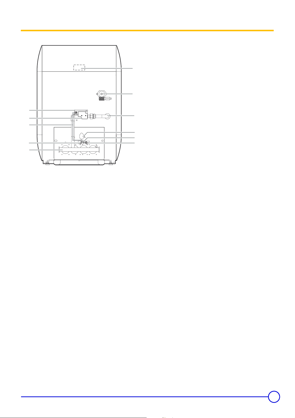
3.3 Main parts
10
11
1. Safety box: Mounted on the gas block to ensure and check ignition sequences, plus burner operation and extinguishing sequences.
2. Gas regulation block: It has a progressive opening, regulation valve and safety valve in series which is controlled by the boiler adjustment dial.
3. Gas inlet
4. Burner
5. Flame inspection window
1
2
3
9
5
8
6
7
4
8518N002
6. Ignition electrode: This ensures ignition burner ignition using a high voltage spark.
7. Ionization probe: This detects the presence of a burner ignition flame through ionization.
8. Ignition burner
9. Ignition burner gas supply pipe
10. Downdraught thermostat (located on the rear wall of the anti-
blowback device)
In the event of smoke release, the burner is cut and the boiler
goes into standby for 15 minutes. It must not be switched off or
moved at any time.The boiler restarts normally after this
thermostat has cooled and the 15 minutes has finished (indicated
by an alarm indicator flashing on the control panel).
11. Sensor tube
01/02/11 - 300002915-001-E DTG 130 Eco.NOx
11
Page 12
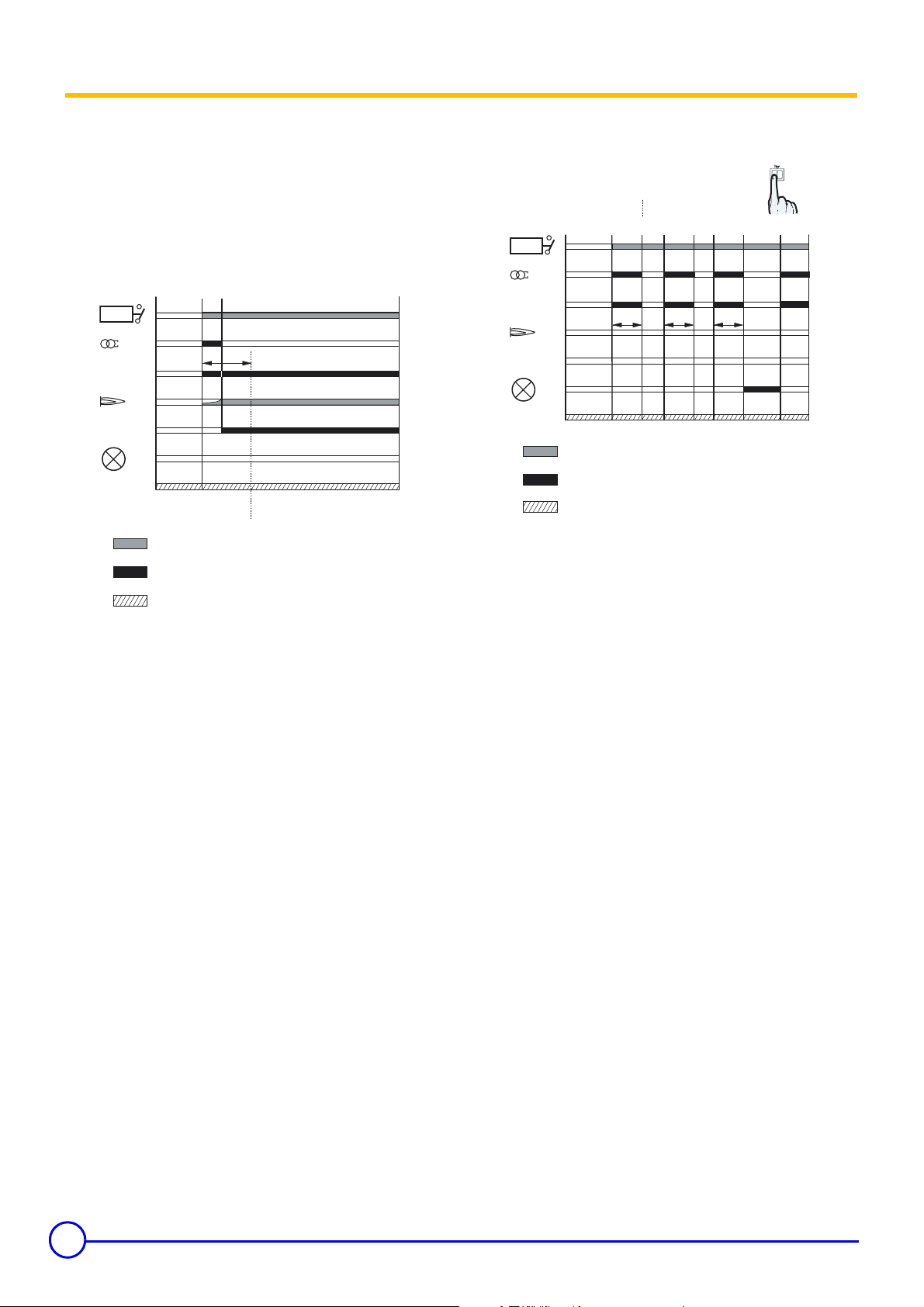
3.4 Operating principle
577 DBC safety box
Operating principle
The ignition and burner surveillance sequences are ensured by the
safety box.
Normal operating cycle
AB
TCH
TA
VBA
SF
VBP
VA
TAF
ts
8518N001
If heating is required, the boiler thermostat TCH closes the contact.
The ignition transformer TA integrated into the safety control box and
the ignition burner valve VBA (supply to the ignition burner) are
switched on.
Gas from the ignition burner is ignited by the ignition electrode and
within the time interval ts; a minimum current of 0.3 µA appears on
the ionization sensor SF and the gas valve regulation flap (supplying
the principal burner) opens.
Operating cycle on safety (start up without flame signal)
TCH
TA
VBA
SF
VBP
VA
TAF
AA1C
CE
ts
1
A
2
ts ts
C
2
8518N044
If a flame is not detected before the safety time ts, the box makes 2
more ignition attempts. If, at the end of the last attempt, there is still
no flame signal, the box goes into safety and the safety indicator
comes on. To restart the heater, press the reset button on the safety
box.
If there is a loss of flame in normal operation, the box automatically
repeats the start up sequence.
Resetting
The box is reset after going into safety by pressing the reset button.
If the reset button does not work, wait at least 15 seconds before
trying a second time.
The box may be on safety on its first start up. Press the resetting
button of the burner.
12
If the reset button is pressed in normal operation, the gas valves
close and the box starts a new ignition sequence.
DTG 130 Eco.NOx 01/02/11 - 300002915-001-E
Page 13

Operating cycle with the downdraught thermostat
cut off
D F
TCH
TA
VBA
SF
VBP
VA
TAF
t
TAF
8518N045
t
n
In the event of smoke release by the anti-blowback device, the antirelease safety device switches off the burner with the safety box on
standby for 15 minutes (this is indicated by an alarm indicator
flashing). The 15 minute timed period can only be interrupted by a
sector cut.
To restart the boiler:
Wait for around 5 minutes (thermostat cooling time) and press the
reset button on the safety control box. If interruptions of this kind
happen repeatedly, contact your fitter.
Legend
A Start of operation
A
Second ignition attempt
1
A
Third ignition attempt
2
B Formation of flame in ignition burner
C End of first ignition attempt
End of second ignition attempt
C
1
On safety through absence of flame signal
C
2
D Anti-blowback thermostat cut
E Resetting
F Restart of the boiler
SF Burner flame signal
TA Ignition transformer
TAF Anti-backflow thermostat
TCH Boiler thermostat
VA Safety lockout warning light
VBA Ignition burner valve
VBP Main burner valve
tn Downdraught thermostat cooling time: times vary
ts Safety time: 55 seconds
Waiting time: 15 minutes
t
TAF
Required input signals
Box output signals
Contact closed
01/02/11 - 300002915-001-E DTG 130 Eco.NOx
13
Page 14

4 Installation
4.1 Regulations governing installation
4.1.1 France
Residential buildings
Statutory terms and conditions of installation and maintenance:
The installation and maintenance of the appliance must be carried
out by a qualified professional in compliance with the statutory texts
of the codes of conduct in force, particularly:
- Order of 27 April 2009 amending the Order of 2 August 1977
Technical and safety rules applicable to combustible gas and
liquefied hydrocarbon installations situated inside residential
buildings and their annexes.
- NF P 45-204 standards
Gas installation, (formerly DTU 61-1, gas installations: April 1982,
addendum no 1: July 1984).
- Local Sanitary Regulations
For appliances connected to the electricity network:
- NF C 15-100 standards Low voltage electrical installation - Rules..
Establishments open to the public
Statutory terms and conditions of installation:
The installation and maintenance of the appliance must be carried
out in compliance with the statutory texts and rules of the codes of
conduct in force, particularly:
- Safety regulations against fire and panic in establishments open
to the public:
a. General regulations
For all appliances:
- Articles GZ - Installations operating on combustible gases and
liquefied hydrocarbons.
Then, depending on use:
- Articles CH-Heating, ventilation, refrigeration, air conditioning and
production of steam and domestic hot water.
b. Instructions specific to each type of establishment open to the
public (hospitals, stores, etc.).
Certificate of compliance
In application of Article 25 of the Order of 27 April 2009 amending the
Order of 2 August 1977 amended and Article 1 of the amended Order
of 05/02/1999, the installer is required to draw up certificates of
conformity approved by the Ministers responsible for construction
and gas safety:
- Different forms (forms 1, 2 or 3) for a new gas installation.
- Model 4 in particular after replacing a furnace with a new one.
4.1.2 Germany
The installation and maintenance of the appliance must be carried
out by a qualified professional in compliance with the statutory texts
of the codes of conduct in force, particularly:
- DIN 4705: calculation of chimney dimensions
- DIN EN 12828 (June 2003 edition): heating systems in buildings.
Planning of hot water heating installations (up to a maximum
operating temperature of 105°C and a maximum output of 1 MW)
- DIN 4753: drinking and industrial water heating installations
- DIN 1988: technical rules on drinking water installations (TRW)
- DVGW-TRGI: technical rules on gas installations, including
complementary equipment
- Working paper DVGW G 260/I: technical rules on the nature of the
gas
14
DTG 130 Eco.NOx 01/02/11 - 300002915-001-E
Page 15

4.1.3 Switzerland
The installation and maintenance of the appliance must be carried
out by a qualified professional in compliance with the statutory texts
of the codes of conduct in force, particularly:
- Directives of the Association des Etablissements Cantonaux
d'Assurance Incendie AEAI
- Local and cantonal regulations
- Directives of the Société Suisse de l'Industrie des Gaz et des Eaux
SSIGE
4.1.4 Other countries
Installation and maintenance of the boiler must be carried out by a
qualified professional in compliance with prevailing local and national
regulations.
4.2 Package list
Description Reference Pack no.
DTG 133 Eco.NOx
DTG 134 Eco.NOx 8518-9004 GL2
DTG 135 Eco.NOx 8518-9005 GL3
Boiler assembly
Control panel
Tank BH 150 8952-9085 GL29
Options available (Refer to the current price list)
Linking kit 8999-7049 EA92
Strengthener 8952-7720 EA82
Conversion kits
(a)
Availability in line with the country's sales plan.
DTG 136 Eco.NOx 8518-9006 GL4
DTG 137 Eco.NOx 8518-9007 GL5
DTG 138 Eco.NOx
DTG 139 Eco.NOx
B (Base) 8518-7000 GL25
D (Diematic 3) 8518-7002 GL27
Propane 8518-7005 GL32
Natural gas H/E - GZ50 8518-7007 GL34
Natural gas L/LL - GZ410 8518-7004 GL31
GZ350 8518-7006 GL33
H - 13 mbar 100003720 GL103
- Directives on liquefied gases, part 2
The safety distance between combustible substances and the boiler
and gaseous effluents must comply with the requirements of the
AEAI standard.
(a)
(a)
(a)
8518-9003 GL1
8518-9008 GL6
8518-9009 GL7
01/02/11 - 300002915-001-E DTG 130 Eco.NOx
15
Page 16

4.3 Mounting
4.3.1 Position of the boiler
A
Installations possible:
- in the kitchen
- in the cellar
- in the boiler house
Clearance to allow for:
- 5 cm on one of the boiler sides (B)
- 70 cm minimum in front
- 5 at the rear (A)
Also have the required space for installing the expansion reservoir
and the heating circulator.
B
4.3.2 Ventilation
Do not obstruct the air inlets in the room (even partially).
France: the cross section of the aeration vent, which is compulsory
in the boiler room in which the boiler is installed, must comply with the
DTU 61.1 (P 45 204) standard and, in particular, with the instruction
on boiler room layout (Book 1764 April 1982).
Germany: the cross section of the ventiliation vents, which are
compulsory in the room in which the boiler is installed, must comply
with the VDI 2050 form 1 standard and with other prevailing
regulations.
Other countries: the cross section of the aeration inlet, which is
compulsory in the premises in which the boiler is installed, must
comply with the standards in force in the country.
Caution:
In order to avoid damage to the boiler, it is necessary to prevent the
contamination of combustion air by chlorine and/or fluoride
compounds, which are particularly corrosive. These compounds are
present, for example, in aerosol sprays, paints, solvents, cleaning
products, washing products, detergents, glues, snow clearing salts,
etc. Therefore:
- Do not pull in air evacuated from premises using such products:
hairdressing salons, dry cleaners, industrial premises (solvents),
premises containing refrigeration systems (risk of refrigerant
leakage), etc.
- Do not stock such products close to the boilers.
If the boiler and/or peripheral equipment are corroded by such
chloride or fluoride compounds, the contractual guarantee
cannot be applied.
16
DTG 130 Eco.NOx 01/02/11 - 300002915-001-E
Page 17

4.3.3 Main dimensions
DTG 130 Eco.NOx
A
850
DTG 1300 Eco.NOx/B 150 - Right
L
850
F
601
C
5
ØB
= =
H
1
(1)
4
345
373
194
2
3
D
E
5
ØB
1
100
G
583
39
30
15
413
846
F
DTG 1300 Eco.NOx/B 150 - Left
L
850
846
413
2
3
9
F
5
ØB
E
29
E
= =
580
450
01/02/11 - 300002915-001-E DTG 130 Eco.NOx
17
Page 18

DTG 1300 Eco.NOx/H 150
té à
600
1578
00
C
200
34
1. Heating flow
R1 (1") for one single boiler
G1 (1") for boiler with DHW tank
2. Heating return
R1 (1") for one single boiler
G1 (1") for boiler with DHW tank
3. Filling and emptying tap
(connection for 14 mm interior diameter pipe)
846
773
601
583
39
413 185
30 (1)
mon
4
1195
580
450
270
4. Gas inlet
5. Smoke nozzle
5
= =
D
gauche ou sans
(2)
ØB
6
7
8
E
ø K
ø B
6. Hot water outlet - R 3/4 (3/4")
7. Circulation - R 3/4 (3/4")
8. Cold water inlet - R 3/4 (3/4")
9. Drain cock
(connection for 14 mm interior diameter pipe)
H
373
1044
1
2
3
9
(3)
monté à droite
Models
DTG ... Eco.NOx
DTG ... Eco.NOx/B 150
DTG ... Eco.NOx/H 150
133
1303
(a)
(a)
134
1304
135
1305
1305
136
1306
1306
137
1307
138
1308
A 522 522 600 600 744 744 822
øB
110 / 111
(b)
110 / 111
(b)
125 / 130
(b)
150 / 153
(b)
150 / 153
(b)
150 / 153
C 1001009385858594
D 74 92 98 66 103 67 70
E 372 372 450 450 594 594 672
F 773 773 773 773 773 773 798
G 728 728 728 728 728 728 768
H 118 82 85 49 85 49 52
øK (inch) R 1/2 R 1/2 R 1/2 R 1/2 R 3/4 R 3/4 R 3/4
L 1122 1122 1200 1200 1344 1344 1422
(a)
Availability in line with the country's sales plan.
(b)
According to the national standard (possible adaptation of the two
diameters)
(1) Adjustable feet : basic sizes : 30 mm.
Can be adjusted from 30 mm to 42 mm.
All height sizes are stated with feet completely screwed in.
R = Thread
G = Exterior cylindrical threading, sealed by sheet gasket
The linking kit is not shown on the central view for easier reading.
All instructions and features for the type BH 150 domestic hot
Z
water tank are stated in the instructions supplied with the tank.
(2) For hydraulic module mounted to the left or without module
139
1309
(b)
180
(3) For hydraulic module mounted on the right
18
DTG 130 Eco.NOx 01/02/11 - 300002915-001-E
Page 19

4.3.4 Assembling the appliance
8518N010B
A
B
Boiler delivered assembled (without control panel)
Take out the shutter + screen assembly
Slide the panel along the front plate.
Push the 1 tubes through the lower opening on the panel case.
Ensure that the centring pins 3 fall into the slots 4.
5. Contact spring
6. Bulbs
Place the bulbs in the sensor tube in front of the boiler. Push
them into the funnel until it butts against it.
2 bulbs (A): Use the contact spring
3 bulbs (B): The contact spring is not used
01/02/11 - 300002915-001-E DTG 130 Eco.NOx
19
Page 20

Attach the anti-release safety device onto the 3 connector studs
on the control panel
Make the electrical connections:
See: Control panel instructions.
Z
4.3.5 Levelling
Thread the connection label into the screen slots. Correctly place
the label using the truncated corner.
- Slightly lift the appliance using a lever.
- Adjust the 4 feet using a flat-bladed screwdriver.
(1)
Adjustable feet :
Basic dimension 0 mm.
Can be adjusted from 0 mm to 12 mm.
20
DTG 130 Eco.NOx 01/02/11 - 300002915-001-E
Page 21

4.4 Hydraulic connections
4.4.1 Regulations
Installation must be carried out in accordance with the prevailing
regulations, the codes of practice and the recommendations in these
instructions.
Installing the boiler in new installations (installations less than 6 months old)
- Clean the installation with a universal cleaner to eliminate debris
from the appliance (copper, flaxen thread, flux).
- Thoroughly flush the installation until the water runs clear and
shows no impurities.
Installing the boiler in existing installations
- Remove sludge from the installation.
- Flush the installation.
- Clean the installation with a universal cleaner to eliminate debris
from the appliance (copper, flaxen thread, flux).
Thoroughly flush the installation until the water runs clear and shows
no impurities.
Installation must be carried out in accordance with the prevailing
regulations, the codes of practice and the recommendations in these
instructions.
Important recommendations for connecting the boiler to the heating circuit
Between the boiler and the safety valves there must be no
complete or partial closing device.
France: DTU - 65.11, § 4.22 - NF P 52-203
Heating installations must be designed and implemented
to prevent heating circuit water and products contained in
it returning to the drinking water system (article 16-7
Departmental Health Regulations). A CB disconnector
(area disconnector for different uncontrollable
pressures)must be installed for filling the heating circuit
according to the NF P 43-011 standard.
Before connecting the heating circuit hydraulic connections, it is
essential to rinse the heating circuits to remove any particles which
might damage certain components (safety valve, pumps, valves...).
In the event where the burner is located at the highest point in the
installation, a dry running or water pressure control device my be
fitted.
4.4.2 Hydraulic connection of the heating circuit
1. Heating flow
2. Heating return
3. Drain cock (connection for 14 mm interior diameter pipe)
Insulate the heating flow and return pipes only outside the
casing.
The drainage device can be connected with a flexible hose.
4.4.3 Hydraulic connection of the water circuit for domestic use
See: Domestic hot water calorifier instructions.
Z
01/02/11 - 300002915-001-E DTG 130 Eco.NOx
21
Page 22

4.4.4 Filling the system
Boiler self-standing:
The installation must be filled via the draining/filling valve. Check that
the entire installation has been correctly bled.
4.4.5 Water treatment
Central heating systems must be cleaned to eliminate
debris (copper, strands, brazing flux) linked to the
installation of the system and deposits that can cause
malfunctions (noise in the system, chemical reaction
between metals). On the other hand, it is important to
protect central heating systems against corrosion, scaling
and microbiological growth by using a corrosion inhibitor
adapted to all types of systems (steel, cast iron radiators,
heated floor, PER)
4.5 Gas connection
It is necessary to abide by the prevailing instructions and regulations.
Each time, a blocking tap will be located as near as possible to the
heater. A gas filter must be fitted to the boiler inlet.
The load loss between the meter and heater must be lower than 1
mbar (heater operating).
With domestic hot water tank:
See: Domestic hot water calorifier instructions.
Z
Switzerland: The water quality must comply with the SICC directives
No. 97-1F "Treatment of water intended for heating, steam,
refrigeration and air conditioning installations".
France
Pipe diameters must be defined in accordance with ATG's
(Association Technique de Gaz) B171 specifications.
Other countries
The diameters of the pipes must be defined in accordance with the
standards in force in your country.
22
DTG 130 Eco.NOx 01/02/11 - 300002915-001-E
Page 23

4.6 Connection to a chimney
A
1
Good
4.7 Electrical connections
Poor
A 40 mm (minimum)
The appliance must be installed in accordance with the Codes of
Practice using a leak proof pipe made of a material capable of
withstanding hot combustion gases and any acidic condensation.
The pipe must be laid out to allow any likely condensation to drain.
It must be in accordance with existing regulations for pipes used for
this purpose. Standard meshed connection pipes are to be avoided.
The pipe connecting the outlet conduit must also be as short as
possible and without a reduced diameter.
The vertical section of the draught diverter outlet must be a minimum
length 3x the diameter of the nozzle before an elbow joint is fitted.
2
The pipe must have a diameter not less than the heater's nozzle
diameter along its whole length. This pipe must be able to be easily
disassembled and must not have a sudden change in diameter.
The outlet conduit must be maintained in a good condition, checked
and cleaned at least once a year.
Only qualified professionnals may carry out electrical
connections, always with the power off.
Do not modify the connections inside the control panel.
Make the electrical connections of the appliance according to:
- The instructions of the prevailing standards,
- The instructions on the circuit diagrams provided with the
appliance,
- The recommendations in the instructions.
Standards to be respected
France: Electrical connections must be in compliance with the NF C
15.100 standard.
Other countries: The electrical connections shall comply with
standards in force.
Rules to be respected
- Power the appliance via a circuit which includes a remote
omnipolar switch with a gap of more than 3 mm.
- Connect all of the cables to the terminal blocks in the control panel.
Keep to the polarity shown on the terminals: phase (L),
neutral (N) and earth 4.
The available output per outlet is 450 W (2 A, with cos ϕ =
0.7) and the inrush current must be lower than 16 A.
If the charge exceeds one of these values, relay the
command using a contactor (fitted outside the control
panel).
Separate the sensor cables from the 230 V cables.
Outside the boiler : Use 2 pipes or cable guides at least
10 cm apart.
For the 230 V electrical connections, use 3-wire cables with a crosssection of 0.75 mm². For other electrical connections, use the 3 wire
cable with a diameter of 0.75 mm².
Make the electrical connections:
Control panel instructions.
Z
Options brochure.
Z
4.8 Skeleton Diagrams
Control panel instructions
Z
01/02/11 - 300002915-001-E DTG 130 Eco.NOx
23
Page 24

5 Commissioning
Initial commissioning must be done by a qualified
professional.
5.1 Control panel
Control panel instructions
Z
5.2 Check points before commissioning
Hydraulic circuit
- Check that the installation and boiler are adequately filled with
water and correctly irrigated and bled.
- Check that there are no leaks on the hydraulic connections.
5.3 Commissioning procedure
Initial commissioning must be done by a qualified
professional.
1. Check the water pressure in the installation. Top up with more
water if necessary.
2. Open the gas valve.
3. Check that the safety thermostat has not triggered. Remove the
safety thermostat hood and press the reset button with a
screwdriver.
4. Set the On/Off switch to 8.
5. Make the settings on the control panel
Gas circuit
- Check that the appliance is properly set for the type of gas used. If
this is not the case:
5.4 Gas settings (Page: 25)
Z
- Check the supply pressure.
- Check the pressure at the nozzles.
5.4.6 Pressure setting and marking of calibrated injectors
Z
(page: 27)
Control panel instructions
Z
24
DTG 130 Eco.NOx 01/02/11 - 300002915-001-E
Page 25

5.4 Gas settings
DTG 130 Eco.NOx boilers are delivered preset for operation on
natural gases of H/E groups.
For operation on another group of gases, carry out the following
operations.
5.4.1 Changing the burner injectors
These actions must be carried out by a qualified
technician.
Cut the electricity and gas supply to the boiler.
Lift out the injector with a number 12 spanner assemble the new
injectors with their new joint.
Models DTG
Natural gas H/E
GZ50
Natural gas L/LL
GZ410
Propane 140A 1.40
H - 13 mbar 225B 2.25
GZ350 310B 3.10
Reassembly:
Correctly replace the seals.
First tighten the injectors by hand and carefully lock them using
a spanner.
133 to 137 204B 2.04
138 to 139 210B 2.10
Nozzle
marking
245B 2.45
Nozzle
diameter (mm)
5.4.2 Changing the ignition burner injector
4
1
Unscrew the connecting nut (14 spanner)
Pull the gas supply pipe towards yourself
Take out the ignition burner nozzle
Fit the new nozzle
Nozzle diameter
(mm)
Natural gas H/E
GZ50
Nozzle marking
40.40
Carry out a gas tightness check
Nozzle marking
Natural gas L/LL
(France)
Natural gas L/LL
≠ France)
(
3
Re-attach the supply tube (14 spanner)
GZ410
Propane 3 0.30
H - 13 mbar 4 0.40
GZ350 6 0.60
Carry out a gas tightness check.
40.40
50.50
Nozzle diameter
(mm)
01/02/11 - 300002915-001-E DTG 130 Eco.NOx
25
Page 26

5.4.3 Setting the injector pressure
Turn the boiler on.
.5.2 Check points before commissioning (page: 24)
Z
5.3 Commissioning procedure (page: 24)
The pressure must be set by a qualified professional.
- Connect a manometer to the pressure socket located on the
manifold.
- Remove the protective cover
using a screwdriver.
- Set the pressure on the injectors by moving the gas regulator on
the valve:
: Increase the pressure
: Reduce the pressure
Natural gas H/E
GZ50
Natural gas L/LL 12.1
GZ410 12.5
Propane 29
H - 13 mbar
GZ350
DTG 133 to 137
DTG 138 to 139
on the regulator by unscrewing it
Manifold pressure (mbar)
16
15
8.4 to 10.2
depending on the model
6 to 7
depending on the model
5.4.4 Setting the start up pressure
E Protective hood
F Ionization probe connection
G Ignition electrode connection
Start up pressure may be set if necessary using a flat screwdriver,
after the protection has been removed E.
Start up pressure is set in the factory on minimum. If it is necessary
to optimise heater start up, it may be set on another value between
0º and 270º.
Gas valve opening diagram
Downstream pressure (mbar)
Time (s)
26
DTG 130 Eco.NOx 01/02/11 - 300002915-001-E
Page 27

5.4.5 Attaching the label
Affix the label which indicates for which type of gas the boiler is fitted
and set.
5.4.6 Pressure setting and marking of calibrated injectors
Models DTG ... Eco.NOx
Burner
nozzles
Manifold
pressure
Gas flow
rate
(1)
15 °C - 1013 mbar
(a)
133
Natural gas H/E
GZ50
Natural gas L/LL
GZ410
Propane 140A 140A 140A 140A 140A 140A 140A
H - 13 mbar 225B 225B 225B 225B 225B 225B 225B
GZ350 310B 310B 310B 310B 310B 310B 310B
Natural gas H/E
GZ50
Natural gas L/LL mbar 12.1 12.1 12.1 12.1 12.1 12.1 12.1
GZ410 mbar 12.5 12.5 12.5 12.5 12.5 12.5 12.5
Propane mbar 29 29 29 29 29 29 29
H - 13 mbar mbar 10.2 10.2 10.2 10.2 10.2 9.6 8.4
GZ350 mbar777776.26
Natural gas H/E
GZ50
Natural gas L/LL
GZ410
Propane Kg/h 1.04 1.56 2.07 2.59 3.10 3.60 4.11
H - 13 mbar
GZ350
mbar 16 16 16 16 16 15 15
3/h(1)
m
3/h(1)
m
(1)
m3/h
3/h(1)
m
(1)
m3/h
204B 204B 204B 204B 204B 210B 210B
245B 245B 245B 245B 245B 245B 245B
1.42 2.13 2.83 3.52 4.22 4.91 5.60
1.65 2.47 3.29 4.10 4.91 5.71 6.51
1.71 2.56 3.41 4.25 5.09 5.92 6.75
1.42 2.13 2.83 3.52 4.22 4.79 5.13
1.97 2.95 3.92 4.89 5.87 6.50 7.29
134 135 136 137
(a)
Availability in line with the country's sales plan.
138
(a)
139
(a)
5.5 Checks and adjustments after commissioning
Carry out all the checks mentioned in the chapter "Checking
Z
and maintenance" (Page: 29).
5.6 Changing the settings
Control panel instructions
Z
01/02/11 - 300002915-001-E DTG 130 Eco.NOx
27
Page 28

6 Switching off the boiler
Set the On/Off switch to 0.
On the Off position 7, the domestic hot water calorifier
fitted with a titanium anode is not protected against
corrosion.
6.1 Precautions to take if there is a danger of frost
Heating circuit:
Use a correctly dosed antifreeze to prevent the heating water
freezing. If this cannot be done, drain the system completely. In all
cases, consult the fitter.
Domestic hot water circuit:
Drain the domestic water tank and pipes.
6.2 Precautions to take in the event of prolonged shutdown (one year or more)
- Close the gas valve
- The boiler and the chimney must be swept carefully.
Close the door of the boiler to prevent the internal circulation of air.
28
DTG 130 Eco.NOx 01/02/11 - 300002915-001-E
Page 29

7 Checking and maintenance
7.1 Checks
Make the following checks at least 1 time a year:
- Water level
- Safety devices
- Checking the ignition burner
- Checking pressure to the nozzle
- Checking burner safety
- Checking the safety thermostat
- Checking the downdraught thermostat
7.1.1 Water level
Regularly check the level of water in the installation. Top it up, if need
be, avoiding the abrupt input of cold water into the hot boiler. If this
operation is repeated several times per season, locate the leak and
repair it.
7.1.2 Safety devices
Check the safety devices (particularly the valve or safety unit),
referring to the instructions provided with these components.
7.1.3 Checking the ignition burner
Do not drain the installation, except in cases of absolute
necessity. For example: Several months' absence with the risk
of ice in the building.
1. Ionization probe
2. Ignition electrode
3. Flame diffuser
4. Earth electrode
Check the position of the ionization probe 1, the ignition electrode
gap 2 and the position of the flame diffuser 3 in terms of the sizes
indicated on the drawing (required in the event of heater
malfunction).
01/02/11 - 300002915-001-E DTG 130 Eco.NOx
29
Page 30

7.1.4 Checking pressure to the nozzle
7.1.5 Checking burner safety
- Unscrew the screw inside the nozzle pressure socket a few turns.
- Connect a manometer to the pressure outlet. Check that the
pressure is correct.
Manifold pressure
(mbar)
Natural gas H/E
GZ50
Natural gas L/LL 12.1
GZ410 12.5
Propane 29
H - 13 mbar
GZ350
- Tighten the pressure socket screw.
Carry out a gas tightness check.
DTG 133 to 137
DTG 138 to 139
16
15
8.4 to 10.2
depending on the model
6 to 7
depending on the model
Close the gas valve. Check the reaction of the safety system. (Safety box on safety
because of ionization fault).
7.1.6 Checking the safety thermostat
Place the Summer/Winter switch on % to cut the heating
accelerator to prevent the temperature rising in the installation.
Place the 3 position switch "
STB position. The burner starts regardless of the setting. Keep the
switch in this position until the safety thermostat cuts (110ºC).
- AUTO - TEST STB" on the TEST
!
To restart the heater, press the safety thermostat reset button and
repeat the starting operations.
7.1.7 Checking the downdraught thermostat
In the event of smoke release by the anti-blowback device, the antirelease safety device switches off the burner with the safety box on
standby for 15 minutes (this is indicated by an alarm indicator
flashing).
Check that the anti-overflow system is working correctly on
commissioning for the first time and during annual servicing of the
boiler.
Checking procedure
Only a qualified professional may carry out the check.
Ensure correct ventilation in the premises during the check.
- Turn of the heater and take out the smoke duct linking the heater
to the chimney. Block the boiler flue gas nozzle using a metal plate
(or other heat-resistant material).
- On start up, combustion products are evacuated to the back of the
heater by the anti-blowback device opening inside.
- The anti-blowback thermostat triggers for a few seconds, cuts the
burner and starts the safety box timer (alarm indicator flashing).
- After checking, re-assemble the smoke duct connecting the heater
to the chimney. Wait for about 5 minutes (thermostat cooling time)
the cut and reconnect the current using the Start/Stop switch. The
boiler restarts.
30
DTG 130 Eco.NOx 01/02/11 - 300002915-001-E
Page 31

7.2 Maintenance
Carry out the following maintenance at least 1 time a year:
- Cleaning main burner and ignition burner
- Cleaning of the heating body
- Cleaning painted surfaces
7.2.1 Cleaning main burner and ignition burner
Cut the electricity and gas supply to the boiler.
Main burner
Clean the burner trains (slits) using a soft brush, a short-
handled brush or a vacuum cleaner.
Do not use a metal brush.
On reassembly, replace the burner earth wire fixed to the
right holding nut on the burner drawer.
Ignition burner
Clean the filter and the ignition burner injector.
Remove ionization probe 1 and the earth electrode 4 deposits
(for example using sand paper).
Carry out a gas tightness check.
01/02/11 - 300002915-001-E DTG 130 Eco.NOx
31
Page 32

7.2.2 Cleaning of the heating body
1
2
3
4
If it is necessary to sweep the boiler, remove the burner drawer to
prevent deposits and soot blocking the orifices in the gas trains.
With the burner out:
- Remove the upper panel from the boiler.
- Remove the top insulating material.
- Remove the sweeping hatch from the draught diverter.
- If necessary, clean the boiler body using the special brush
provided.
- Clean the combustion chamber using a vacuum cleaner.
8518N016
7.2.3 Cleaning painted surfaces
- Use a soapy solution and a sponge only.
- Rinse with clean water.
- Dry with a soft cloth or a chamois leather.
32
DTG 130 Eco.NOx 01/02/11 - 300002915-001-E
Page 33

7.3 Troubleshooting
7.3.1 Error messages
Control panel instructions
Z
7.3.2 Incidents and solutions
Symptoms Probable causes Solution
The heater does not start and the safety
box is not affected (red alarm indicator
off)
The burner does not ignite and the
safety box is not affected (red alarm
indicator off)
The heater thermostat is requiring
heat
Setting (option) is not requiring
heat
The safety thermostat has been
triggered after overheating
No current
On safety because of a lack of
gas
Gas valve defective Check the gas valve and replace if necessary
No spark from the electrode Check the electric cable connection to the safety box and the electrode
No ionization current
Create a demand by moving the heater thermostat or the setting level
(option)
Solve the cause of overheating and reset the safety thermostat
Set the On/Off switch to
Purge the gas supply pipe then reset the heater using the panel reset button
Check the ionization probe and earth wire connection
Check the position of the ionization probe and the flame diffuser in the
ignition burner
Check for adequate draw on the chimney connection. Reset the safety
control box.
Check that the downdraught thermostat is in good working order. Reset the
safety control box.
8
The burner ignites and the safety box
goes into standby (burner cut and the
alarm indicator flashes)
The burner ignites and the safety box is
affected (alarm indicator on)
The burner ignites but with reduced
power
Dirty cast iron body (hearth)
Noisy heater
Please note the seriousness of unplanned intervention on
the combustion product evacuation checking device:
downdraught thermostat cut.
evacuation faults must be solved by improving the draught
in the chimney.
In the event of a thermostat fault, it must be replaced by a
part stated on our "Spare parts list". Its position must not
be modified, which is defined by the 2 bosses on the
holding bracket which are located in the 2 holes on the
draught diverter. The thermostat must not be placed out of
service.
Inversion of the phase and
neutral wires on the heater's
control panel.
Upstream pressure too weak Check gas supply
Dirty filter Clean the filter
Gas valve unit defective Replace the gas valve unit
Gas valve defective Check gas valve and replace if necessary
Unsuitable injectors Check injectors
Upstream pressure too high Check gas supply
Dirty burner Clean the burner
Insufficient or incorrectly placed
air supply
Gas valve defective Check gas valve and replace if necessary
Poor purge Purge correctly
Body has scale Descale the heating circuit
Unsuitable injectors (Whistling) Check injectors
Connect the phase to terminal 1 and neutral to 2.
Enlarge air supply, smoothen airation holes
01/02/11 - 300002915-001-E DTG 130 Eco.NOx
33
Page 34

Symptoms Probable causes Solution
Heater too hot or too cold for
requirements
Flame returns
Whistling
3 position switch on position
Wrong setting for the heater
thermostat
Injectors too large
Pressure too weak
Injectors too small
Pressure too high
Check the position of the 3 position switch
!
Set the heater thermostat if the heater has SV-matic setting or an ambient
thermostat
Check pressure injectors
34
DTG 130 Eco.NOx 01/02/11 - 300002915-001-E
Page 35

8 Spare parts - DTG 130 Eco.NOx
8.1 Boiler body + Draught diverter + Insulation
To order a spare part, give the reference number shown on the list.
01/02/11 - 300002915-002-C
DE DIETRICH THERMIQUE S.A.S. - Spare parts centre
4, rue d’Oberbronn - F-67110 REICHSHOFFEN -
cpr
dedietrichthermique.com
+33 (0)3 88 80 26 50 - + +33 (0)3 88 80 26 98
*
Page 36

8.2 Gas line + Conversion set
8.2.1 3 sections
8.2.2 4-6 sections
36
DTG 130 Eco.NOx 01/02/11 - 300002915-001-E
Page 37

8.2.3 7-9 sections
8.3 Casing
8.4 Control panels
Control panel instructions
Z
01/02/11 - 300002915-001-E DTG 130 Eco.NOx
37
Page 38

Ref. Code no. Description
Boiler body
1 85188500 Complete base frame - 3 sections
1 85188501 Complete base frame - 4 sections
1 85188502 Complete base frame - 5 sections
1 85188503 Complete base frame - 6 sections
1 85188504 Complete base frame - 7 sections
1 85188505 Complete base frame - 8 sections
1 85188506 Complete base frame - 9 sections
2 97581059 Adjustable feet
3 83755506 Assembled boiler body - 3 sections
3 83755507 Assembled boiler body - 4 sections
3 83755508 Assembled boiler body - 5 sections
3 83755509 Assembled boiler body - 6 sections
3 83755510 Assembled boiler body - 7 sections
3 83755511 Assembled boiler body - 8 sections
3 83755512 Assembled boiler body - 9 sections
4 85188025 Mounting square
5 95365611 1/2" sensor tube - Length 160 mm
6 83750004 Body lifter
7 97549270 Heating flow pipe - 1" - Length 375 mm
8 97549512 Heating return pipe - 1" - Length 135 mm
9 94902073 Drain cock 1/2"
10 94920297 Elbow 1"
Draught diverter
11 85188514 Draught diverter complete - 3 sections
11 85188515 Draught diverter complete - 4 sections
11 85188516 Draught diverter complete - 5 sections
11 85188517 Draught diverter complete - 6 sections
11 85188518 Draught diverter complete - 7 sections
11 85188519 Draught diverter complete - 8 sections
11 85188520 Draught diverter complete - 9 sections
12 97581501 Flue gas nozzle Ø 110/111
12 300000300 Flue gas nozzle Ø 125/130
12 300000301 Flue gas nozzle Ø 150/153
12 97581497 Flue gas nozzle Ø 180
13 85188053 Inspection hatch - 3 sections
13 85188054 Inspection hatch - 4 sections
13 85188055 Inspection hatch - 5 sections
13 85188056 Inspection hatch - 6 sections
13 85188057 Inspection hatch - 7 sections
13 85188058 Inspection hatch - 8 sections
13 85188059 Inspection hatch - 9 sections
14 200000204 Anti-backflow thermostat
15 83758077 Mounting square
16 95363355 Static thermostat
Ref. Code no. Description
17 200000095 Electric circuit - Anti-backflow thermostat
18 83665501 Screw bag
Insulating material for body
19 200000510
19 200000511
19 200000512
19 200000513
19 200000514
19 200000515
19 200000186
20 97550513 Insulation under burner - 3 sections
20 97550514 Insulation under burner - 4 sections
20 97550515 Insulation under burner - 5 sections
20 97550516 Insulation under burner - 6 sections
20 97550517 Insulation under burner - 7 sections
20 97550518 Insulation under burner - 8 sections
20 97550519 Insulation under burner - 9 sections
21 83885655 Insulation back of hearth - 3 sections
21 83885656 Insulation back of hearth - 4 sections
21 83885657 Insulation back of hearth - 5 sections
21 83885658 Insulation back of hearth - 6 sections
21 83885659 Insulation back of hearth - 7 sections
21 83885660 Insulation back of hearth - 8 sections
21 83885661 Insulation back of hearth - 9 sections
22 94285095 Tube of silicon mastic
23 96960227 Brush
50 200003131 Complete gas circuit - 3 sections
51 85185507 FURIGAS burner drawer - 3 sections
52 200003132 Complete gas circuit - 4 sections
52 200003133 Complete gas circuit - 5 sections
52 200003134 Complete gas circuit - 6 sections
53 200003135 Complete gas circuit - 7 sections
53 200003136 Complete gas circuit - 8 sections
53 200003137 Complete gas circuit - 9 sections
54 85185508 FURIGAS burner drawer - 4 sections
54- 85185509 FURIGAS burner drawer - 5 sections
54 85185510 FURIGAS burner drawer - 6 sections
55 85185511 FURIGAS burner drawer - 7 sections
55 85185512 FURIGAS burner drawer - 8 sections
Complete insulating material for body - 3
sections
Complete insulating material for body - 4
sections
Complete insulating material for body - 5
sections
Complete insulating material for body - 6
sections
Complete insulating material for body - 7
sections
Complete insulating material for body - 8
sections
Complete insulating material for body - 9
sections
Gas line
38
DTG 130 Eco.NOx 01/02/11 - 300002915-001-E
Page 39

Ref. Code no. Description
55 85185513 FURIGAS burner drawer - 9 sections
56 83885533 FURIGAS burner + Screws
57 95360220 Pressure socket
58 83754945 Earth cable
59 85188921 Complete ignition burner - 3-7-8-9-10 sections
60 85188922 Complete ignition burner - 4-5-6 sections
61 85185514
62 85185515 Ignition burner gas supply pipe - 4-5-6 sections
63 85185516 Valve
64 85185517 Elbow flange
65 85185518 Right flange
66 95023314 Gasket
67 85185519 Box + Wiring
68 85184904 Burner cable
69 94952101 N374 1/2" x 1" nut
70 94952081 Schraubenmutter N371 1/2"
71 95013062 Green seal 30x21x2
72 97549898 Gas inlet pipe - 3-4-5-6 sections
73 97549899 Gas inlet pipe - 7-8-9 sections
74 83885635 Burner drawer insulation kit 3 sections
74 83885636 Burner drawer insulation kit 4 sections
74 83885637 Burner drawer insulation kit 5 sections
74 83885638 Burner drawer insulation kit 6 sections
75 83885639 Burner drawer insulation kit 7 sections
75 83885640 Burner drawer insulation kit 8 sections
75 83885641 Burner drawer insulation kit 9 sections
76 83665502 Screws
77 85187007 Conversion set H/E/GZ50
77 85187004 Conversion set L/LL/GZ410
77 85187005 Propane conversion kit
86 85188507 Casing - 3 sections
86 85188508 Casing - 4 sections
86 85188509 Casing - 5 sections
86 85188510 Casing - 6 sections
86 85188511 Casing - 7 sections
86 85188512 Casing - 8 sections
86 85188513 Casing - 9 sections
87 85188521 Front plate - 3 sections
87 85188522 Front plate - 4 sections
87 85188523 Front plate - 5 sections
87 85188524 Front plate - 6 sections
87 85188525 Front plate - 7 sections
87 85188526 Front plate - 8 sections
Ignition burner gas supply pipe - 3-7-8-9-10
sections
Casing
Ref. Code no. Description
87 85188527 Front plate - 9 sections
88 97525376 Funnel
89 94820110 Catch
90 94820120 Pin
91 85188528 Complete right hand side panel
92 85188529 Complete left hand side panel
93 200000254 Upper rear panel - 3 sections
93 200000255 Upper rear panel - 4 sections
93 200000256 Upper rear panel - 5 sections
93 200000257 Upper rear panel - 6 sections
93 200000258 Upper rear panel - 7 sections
93 200000259 Upper rear panel - 8 sections
93 200000270 Upper rear panel - 9 sections
94 85188542 Lower back panel - 3 sections
94 85188543 Lower back panel - 4 sections
94 85188544 Lower back panel - 5 sections
94 85188545 Lower back panel - 6 sections
94 85188546 Lower back panel - 7 sections
94 85188547 Lower back panel - 8 sections
94 85188548 Lower back panel - 9 sections
95 85188549 Complete door - 3-4 sections
95 85188550 Complete door - 5-6 sections
95 85188551 Complete door - 7-8 sections
95 85188552 Complete door - 9 sections
96 85188553 Complete top panel - 3-4 sections
96 85188554 Complete top panel - 5-6 sections
96 85188555 Complete top panel - 7-8 sections
96 85188556 Complete top panel - 9 sections
99 85188535 Additional part set
100 97525372 Narrow screen
101 97525373 Wide scren
102 97525374 Narrow shutter
103 97525375 Wide shutter
104 97525370 Narrow body
105 97525371 Wide body
106 200001290 Housing screws packet
Control panels
Control panel instructions
Z
GL25 B control panel
GL27 D control panel
01/02/11 - 300002915-001-E DTG 130 Eco.NOx
39
Page 40

FR
DE DIETRICH THERMIQUE S.A.S.
www.dedietrich-thermique.fr
Direction des Ven te s France
57, rue de la Gare
F- 67580 MERTZWILLER
+33 (0)3 88 80 27 00
+33 (0)3 88 80 27 99
AT
ÖAG AG
www.oeag.at
Schemmerlstrasse 66-70
A-1110 WIEN
+43 (0)50406 - 61624
+43 (0)50406 - 61569
dedietrich@oeag.at
DE
BE
CH
DE DIETRICH REMEHA GmbH
www.dedietrich-remeha.de
Rheiner Strasse 151
D- 48282 EMSDETTEN
+49 (0)25 72 / 23-5
+49 (0)25 72 / 23-102
info@dedietrich.de
VAN MARCKE
www.vanmarcke.be
Weggevoerdenlaan 5
B- 8500 KORTRIJK
+32 (0)56/23 75 11
WALTER MEIER (Klima Schweiz) AG
www.waltermeier.com
Bahnstrasse
CH-8603 SCHWERZENBACH
+41 (0) 44 806 44 24
Serviceline +41 (0)8 00 846 846
+41 (0) 44 806 44 25
ch.klima@waltermeier.com
24
LU
RU
NEUBERG S.A.
www.dedietrich-heating.com
39 rue Jacques Stas
L- 2010 LUXEMBOURG
+352 (0)2 401 401
DE DIETRICH
www.dedietrich-otoplenie.ru
129090 г. Москва
ул. Гиляровского , д. 8
офис 52
+7 495 988-43-04
+7 495 988-43-04
dedietrich@nnt.ru
WALTER MEIER (Climat Suisse) SA
Z.I. de la Veyr e B, St-Légier
CH-1800 VEVEY 1
+41 (0) 21 943 02 22
Serviceline +41 (0)8 00 846 846
+41 (0) 21 943 02 33
ch.climat@waltermeier.com
DE DIETRICH
www.dedietrich-heating.com
CN
Room 512, Tower A, Kelun Building
12A Guanghua Rd, Chaoyang District
C-100020 BEIJING
+86 (0)106.581.4017
+86 (0)106.581.4018
+86 (0)106.581.7056
+86 (0)106.581.4019
contactBJ@dedietrich.com.cn
© Copyright
All technical and technological information contained in these technical instructions, as well as any
drawings and technical descriptions supplied, remain our property and shall not be multiplied
without our prior consent in writing.
Subject to alterations.
01/02/11
AD001-AC
DE DIETRICH THERMIQUE
57, rue de la Gare F- 67580 MERTZWILLER - BP 30
 Loading...