

Page 1
4 feux gaz
4 gas ring
3 feux gaz
+ 1 foyer électrique
3 gas ring
+ 1 electric hotplate hob
Le guide d’utilisation de
votre table de cuisson
Hob operating guide
FR
GB
Page 2
23
In this Manual,
displays safety instructions
displays tips and hints
List of contents
Using your hob in complete safety 25
What your hob looks like? 26
Installing your hob in all simplicity 27
Fitting recommendations 27-29
Electrical connections 30
Gas connections 31-32
Changing the type of gas supply 33-37
Using your hob in all simplicity 38
How to use your gas burners? 38
Which pans are best adapted for use 39
on the gas burner?
How to use the electric hotplate? 40
Which pans are best adapted for use on the electric hotplate? 40
How to look after your hob? 41
Minor troubleshooting 42
Gas-cooking guide 43
Cooking guide for electrical hobs 43
GB
Page 3

24
Dear Customer,
Thank you for buying a DE DIETRICH hob.
Our research teams have designed a new generation of kitchen
appliances. As a result of our unique expertise, we have produced
a range of goods whose quality, design and technical advance are
unsurpassed.
You will find that the clean lines and modern look of your
DE DIETRICH hob blends in perfectly with your kitchen décor. It
is easy to use and performs to a high standard.
DE DIETRICH also makes a range of products that will enhance
your kitchen such as hobs, extractor hoods, built-in dishwashers
and refrigerators. There are models to complement your new DE
DIETRICH hob.
Of course, we make every effort to ensure that our products meet
all your requirements, and our Customer Relations department is
at your disposal, to answer all your questions and to listen to all
your suggestions (see back cover of manual).
DE DIETRICH is certain that by setting new standards of
excellence by which comparisons can be made, customers will
find that DE DIETRICH appliances offer a better and more
exciting way of living.
DE DIETRICH.
Editorial
Page 4
25
- We have designed your hob for private
domestic use.
- With a view to the constant
improvement of our products, we reserve
the right to make any changes in their
technical, functional or aesthetic
characteristics as a result of technical
evolution.
- These hobs are designed exclusively for
the cooking of drinks and foodstuffs.
These products do not contain any
asbestos-based component parts.
- Using a gas-powered hob produces both
heat and humidity in the room where it is
used.
Make sure your kitchen is well
ventilated :
keep all natural air-vents open or have a
mechanical ventilation system installed (a
mechanically ventilated hood) with a
minimum airflow of 2m
3
/h.
- You must always keep an eye on your
cooking.
- Please read the instructions before
installing and using this appliance.
- Never leave any CLEANING OU
INFLAMMABLE
products in the cupboard or
drawer beneath your hob (aerosols or
other pressurised cans, papers, recipe
books, etc.).
- If you use a drawer under your hob, we
advise you not to keep any objects in it
that are liable to suffer from heat (plastic,
paper, aerosols, etc.).
- Prolonged, intensive use of the hob may
require extra ventilation; by opening a
window for example or producing more
Your hob in complete safety
efficient ventilation by increasing the
power of the existing mechanical
ventilation.
- Disconnect your hob from both electrical
and gas supplies before carrying out any
maintenance operations.
- If you plug in any electrical appliance
near the hob, make sure that its power
cable is not in contact with any source of
heat.
- For safety reasons, do not forget to
close the main gas valve for built in gas
lines or the valve on the top of your
butane/propane gas cylinder.
- If a knob is difficult to turn,
DO NOT
FORCE IT
. Call up your installer.
- The EC mark of conformity can be found
on all these hobs.
Using your hob in complete safety
YOUR HOB IS DELIVERED PRE-SET FOR USE WITH NATURAL TOWN GAS.
Page 5
26
①①
Right back burner switch
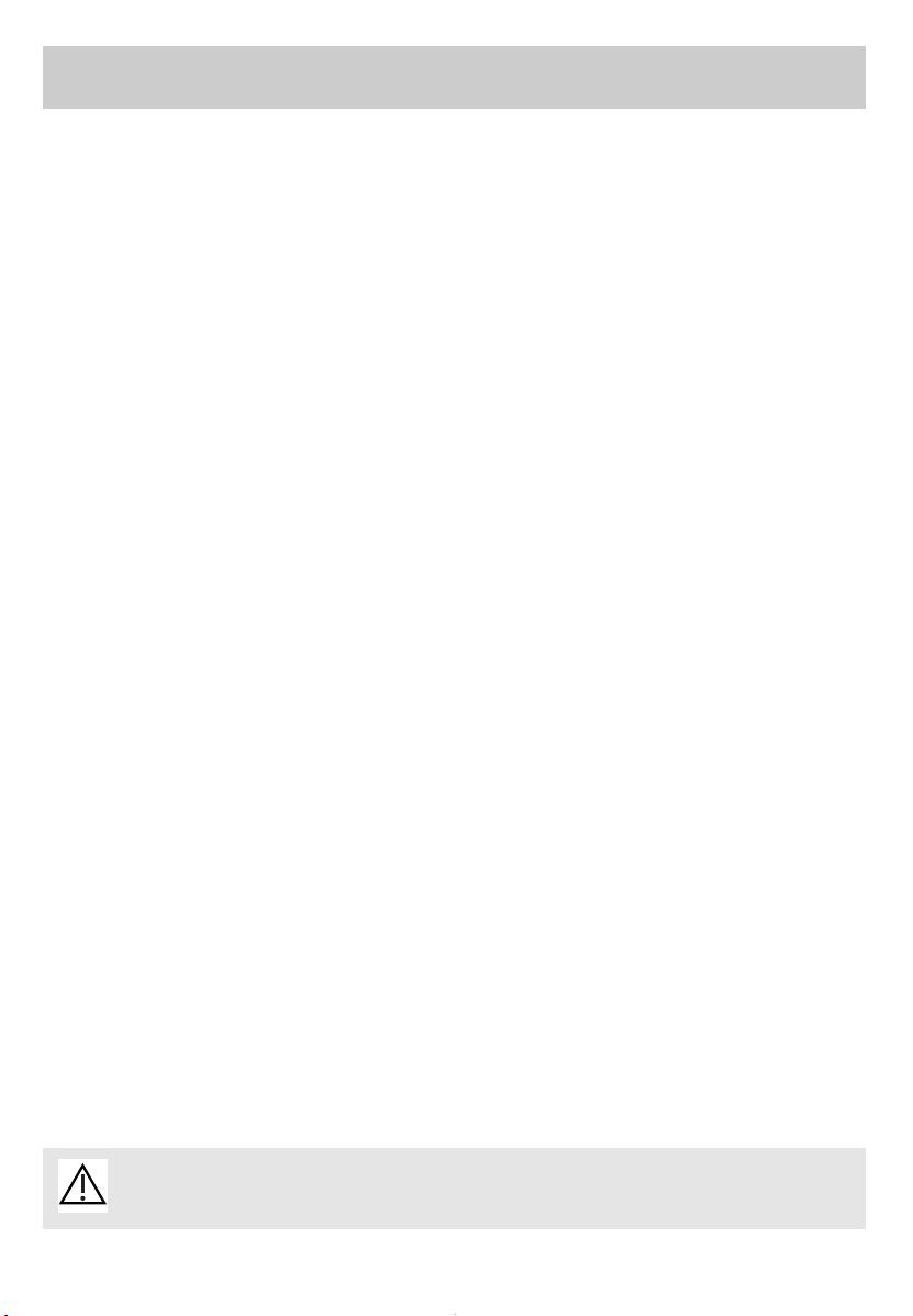
What your hob looks like?
4 gas ring hob
3 gas ring + 1 electric hotplate hob
Semi-fast
burner
②②
Double-crown
burner
③③
Fast burner
①①
Auxiliary
burner
④④
②②
Left back burner switch
③③
Front left burner switch
④④
Front right burner switch
①①
Right back burner switch
②②
Left back burner switch
③③
Front left burner switch
④④
Front right burner switch
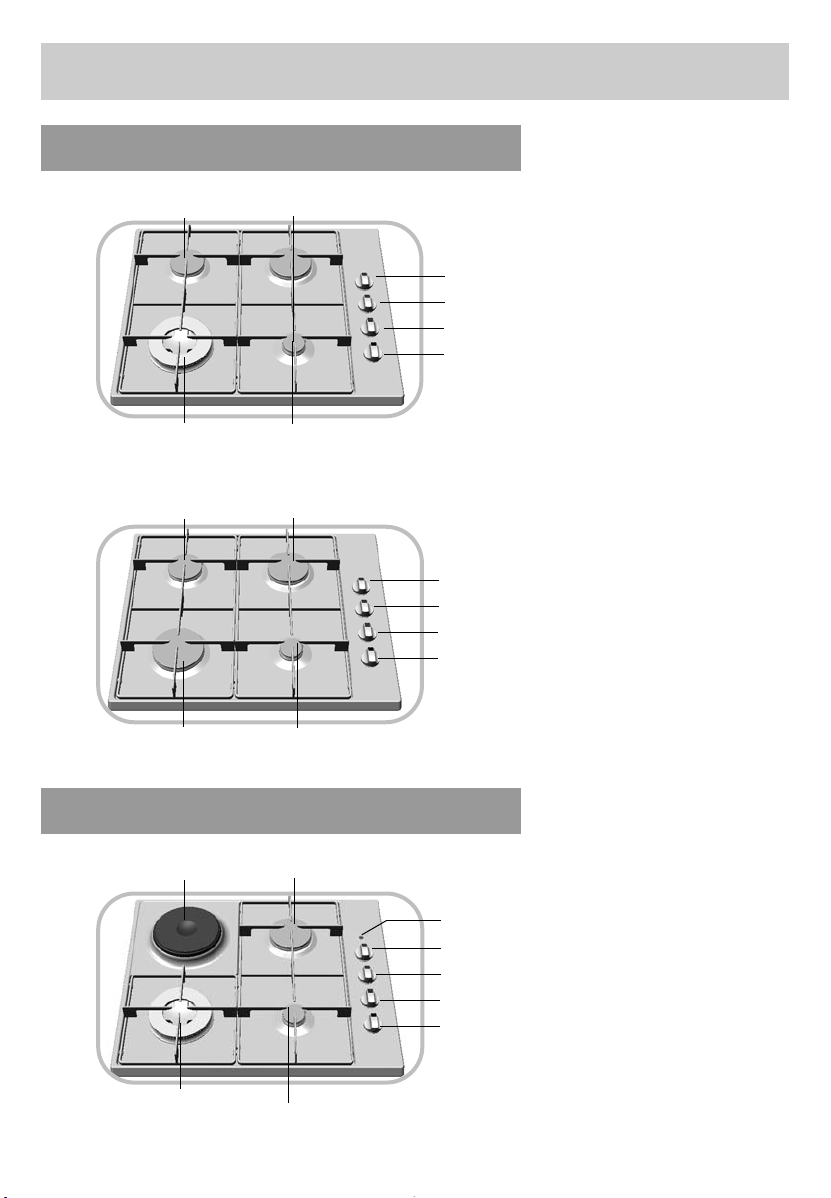
②②
Right back burner switch
electric hotplate
hob
⑤⑤
Double-crown
burner
④④
Fast burner
②②
Auxiliary
burner
③③
①①
Electric ring indicator
③③
Front right burner switch
④④
Front left burner switch
⑤⑤
Electric ring switch
Semi-fast
burner
②②
Extra fast burner
③③
Fast burner
①①
Auxiliary
burner
④④
Page 6
27
This appliance should be installed by a
qualified technician / installer.
Prior to installation, ensure that the
local distribution conditions (nature of
the gas and gas pressure) and the
adjustment conditions of the
appliance are compatible.
The adjustment conditions are stated on a
label in the wallet and also on the
packaging.
This appliance must be installed and
connected in accordance with your
country's regulations. It must be used in a
place that is well-ventilated. Please read the
instructions before installing or using.
Installing your hob in all simplicity
This appliance is not connected to a smoke
extractor. Please ensure that its installation
complies with ventilation requirements.
On this subject, combustion can take place
only if oxygen from the air is present, so
this air must be constantly renewed and
the combustion products must be
evacuated (a minimum air input of 2 m
3
/h
per kW of gas energy is required).
•
These hobs comply with the requirements of heating in accordance with standard EN 60.335.2.6 and Class 3 for installation itself (in accordance with standard EN
30.1.1).
Fitting recommendations
Keep this guide near your appliance and stick the identity label to the last
page.
Cut-out
Model
Width
Depth Height
Depending on cupboard
Outside
dimensions above
the work surface
60 cm
52 cm
5,6 cm
Outside
dimensions under
work surface
55 cm 47,5 cm 3,4 cm
49 cm
56 cm
Page 7

28
Installing your hob in all simplicity
The hob must be built into the worktop of a support cupboard. This worktop must be at least 3 cm thick and
heat-resistant or else coated with a
heat resistant material.
A side-clearance of at least 30 cm
should be left to the right and left of
the hob. A tall cupboard or partition
too close to the hob would hinder free
movement of kitchen utensils.
If a horizontal partition is put under
the hob, it must be placed between 10
and 15 cm from the bottom of the
worktop. In any case, do not keep any
sprays or pressurized containers in
the compartment which could be just
under the hob.
To prevent any foreign bodies or liquid from getting between the hob
and the worktop,
stick the foam seal
provided in the wallet in position before
installing the hob
. This will also protect
your work surface from the heat given
out by the hob.
1- remove the pan support grates,
the burner caps and heads after checking their position.
2- Turn the hob over and place it
gently over the opening in the worktop paying attention not to damage
the control knobs, thermocouples and
lighters.
3- Stick the foam seal around the
outside of the hob. This foam seal
ensures that no water can seep between the top of the hob and the surrounding work surface. It also helps
to insulate the work surface from the
heat of the hob.
4- Put the hob back the right way
up and place the burners, caps and
pan grates back in position.
Fitting recommendations (cont'd)
Casing
Foam seal
70 cm mini
30 cm
m
ini
5,3 cm m
ini
49 cm
56 cm
3 cm mini
30 cm
m
ini
Page 8

29
Installing your hob in all simplicity
- Place the hob in position in the worktop
cut-out taking care to centre it as well as
possible.
- replace the burner heads, the burner
caps and the pan stands.
- Connect the hob power cable to your
kitchen electricity supply (See "Elec-
trical Connections").
-Connect to your gas supply (see "How
to connect the hob to the mains gas
supply" or "How to connect the hob
to butane or propane gas").
If you want, you can fix the hob in position on its four corners, using the four
lugs and screws provided (See diagram).
Only use the holes provided,
Shown by arrows on the hob unit
(see diagram opposite)
Stop screwing when the lug
starts to bend.
Do not use a power screwdriver.
Fitting recommendations (cont'd)
Worktop
Mounting pad
Underside of the hob unit
Mounting pad FRONT
Mounting pad BACK
Connector terminal
Fixing holes, shown by
arrows
Page 9

30
Cable
H05V2V2F - T90
Cross section of
conductors in
mm
2
Fuse
220-240 V~- 50 Hz
All-gas and
mixed
3 conductors of
which 1 is to be
earthed
1
10 A
CROSS SECTION OF THE CABLE TO USE
Installing your hob in all simplicity
Hobs are delivered with a three-conductor (phase + ground + neutral)
H05V2V2F - T90, 1mm section cable,
ref. SAV : 77X3767 and must be
connected to a 220-240 V~ single phase mains supply by the intermediary of
a phase + earth + CEI 60083 standardised neutral plug, or a single pole cut-off
device with a contact opening by at
least 3mm.
The mains plug must be accessible after
installation.
Electrical connections
The protective conductor is connected to the earth connection on the hob
and therefore must also be connected to an external earth connection .
Use a 10 A fuse.
If the supply cable is damaged it must be replaced by a cable or a special unit available from the manufacturer or its After-Sales Service.
● Mixed and all-gas hobs
Page 10

31
Installing your hob in all simplicity
Gas connections
● Possible connections
One of the 3 following connections must
be used:
-
connection with a rigid pipe
(gas
standard G1/2).
The connection should be made at the end of
the elbow seal on the appliance,
or -
connection with a reinforced,
braided, flexible gas hose with threaded connectors
(fig. A).
You may also use a "Gazinox" type, stainless steel flexible tube available from your
local distributor,
or
- connection with a flexible gas ho-
se with threaded connectors
(fig. B).
These hoses must not exceed 2 metres
in length and their entire length must be
accessible.
NATURAL GAS
Meter
fig.A fig.B
Reinforced, braided,
flexible gas hose with
threaded connectors
Flexible gas hose with
threaded connectors
● Preliminary remarks
Access to the whole length of the connection hose must be possible and the gas hose
must be replaced before its use before date (indicated on the hose).
Whatever means of connections is chosen, make sure that it is gas sound after installa-
tion by using soapy-water.
If the hob is to be installed above an oven
or if other nearby heating appliances risk
heating and damaging the gas hose then it
is essential that a rigid pipe be installed
instead.
If a flexible hose is used (in the case of
butane gas) then it must not be installed
in a place where it may be in contact with
a moving part of the kitchen unit or a place likely to get cluttered.
TOWN GAS (NATURAL GAS)
Page 11

32
Installing your hob in all simplicity
Gas connections (Cont'd)
For the user's safety, we advise the
connection to be made with a rigid pipe if this is possible, or with a reinforced, braided, flexible gas hose (maximum length 2 metres) (fig. A).
For an existing installation, where
it is not possible to fit a reinforced,
braided, flexible gas hose, the connection can be made with a flexible gas
hose (maximum length 2 metres), wi-
th two jubilee clips: one on the
connector (fig. B), and the other on
the pressure regulator, and a gas
proof washer should be fitted between
the connector and the elbow seal on
the hob.
You will find the sealing washer and
the adaptor in the wallet delivered with the unit.
BUTANE/PROPANE
Pressure regulator compulsory
propane
butanene
propane
Gas proof
washer
(supplied)
Jubilee clip
(supplied)
Jubilee clip
(not supplied)
fig. A
fig. B
Reinforced,
braided, flexible
gas hose with
threaded
connectors
Flexible hose
connection
propane
Temperatures above 30°C would cause overheating of the gas hose. To
avoid this, check that there are no heat-producing devices nearby.
Screw on the connector with a torque not exceeding 2.5 m/daN (m/kgF).
BOTTLED OR TANKED GAS
(BUTANE/PROPANE).
Page 12

33
Installing your hob in all simplicity
Changing the type of gas supply
● Preliminary remarks
Your hob is delivered regulated
for natural gas.
The injectors for adapting the hob for use
with butane or propane are in the wallet
containing the instructions, together with
the adaptor and the sealing washer. Please
see the corresponding paragraph on
"Gas Connections".
You can obtain an adapter sachet
from your After-sales Service.
Every time you change your gas
supply, mark the square on the label
in the wallet that corresponds to the
new type of gas (See "Gas Rating" in
this chapter).
Page 13

34
Installing your hob in all simplicity
Changing the type of gas supply (cont'd)
When carrying out this operation, you
should successively :
➊
Adapt the gas connection
❷
Change the injectors
❸
Adjust the retarder on the taps
➊
A
DAPT THE HOB CONNECTION
to the new
gas adjustment. Refer to the paragraph
“Gas connections”.
❷
C
HANGE THE INJECTORS
in the following
way:
- Remove the supports, and all the burner caps and heads.
- Using the spanner supplied, unscrew
the injectors at the bottom of each dish
and remove them (fig 1).
- Replace these with the injectors
supplied in the wallet, in accordance with the gas rating table at the
end of the chapter; to do this:
➪ Screw in the injectors by hand
until they are tight.
➪ Put the spanner well onto the
injector.
➪ With a pencil draw a line on the
hearth plate as indicated (fig. 2).
➪ Turn the spanner clockwise un-
til the line appears on the other
side (fig. 3). Warning! Do not
go beyond this limit as you
are liable to cause damage.
- Put the burner heads, covers and
pan supports back in position.
Cover
Head
Dish
Injector
Grill
Upper side
of the hob
Spanner
Line
Fig. 3
Fig. 1
Fig. 2
Page 14

35
Installing your hob in all simplicity
Changing the type of gas supply (cont'd)
Knob
Gas tap
Sealing ring
Tap axis
Adjustment
screw
Sealing ring
Fig. 4
❸
ADJUST THE RETARDER ON THE TAPS located under the knobs. Proceed as
follows:
•
Work on one tap at a time.
•
Pull off all knobs and sealing rings.
CHANGING FROM NATURAL GAS TO
BUTANE/PROPANE GAS .
- Using a small screwdriver screw fully the
brass, adjustment screw (yellow) (Fig. 4)
clockwise.
- Check the position of the sealing rings
and knobs before putting them back in
place. Make sure the knobs are pushed
down as far as possible.
CHANGING FROM BUTANE / PROPANE
GAS TO NATURAL GAS OR AIR-PROPANE /
AIR-BUTANE.
- Using the small screwdriver, unscrew the
brass, adjustment screw (yellow) turning it
round twice, anti-clockwise (Fig. 4).
- Push the control knob back in position,
light the burner and turn to maximum power. Then turn the knob back to its low flame position.
- Remove the knob again then turn the adjustment screw clockwise as low as possible without extinguishing the flames.
- Put back the sealing ring and control knob
then turn it several times from maximum
position to minimum position : the flame
must not be extinguished. Otherwise,
re-adjust it by slightly screwing or unscrewing the adjustment screw so that a stable
flame is obtained when the knob is turned
from maximum to minimum position.
Page 15

36
Installing your hob in all simplicity
Changing the type of gas supply (cont'd)
● Gaz rating
PT FR-GB FR-GB FR FR
FR-GB-ES ES-PT ES-PT
Appliance designed for installation: Butane Propane Natural Natural
Air-propane
FR ............................cat : III1C2E+3+ gas gas
Air-butane
ES-GB-PT.................cat : II2H3+ G30 G31 G20 G25 G130
Hourly input -see below: 28-30mbar 37mbar 20 mbar 25 mbar 8 mbar
at 15°C at 1,013 mbar
D
OUBLE-CROWN BURNER (front left) (depending on model)
Indicator marked on injector 95 95 147 147 360
Nominal heat rating (kW) 3,6 3,6 4 4 3,5
Low heat rating (with/without safety device) (kW) 1,45 1,55 1,55 1,3
Hourly output (g/h) 262 257
Hourly output (l/h) 381 443 489
E
XTRA FAST BURNER (front left) (depending on model)
Indicator marked on injector 88 88 137 137 298
Nominal heat rating (kW) 3,1 3,1 3,2 3,2 3,1
Low heat rating (with/without safety device) (kW) 0,83 0,87 0,87 0,78
Hourly output (g/h) 225 221
Hourly output (l/h) 305 354 434
F
AST BURNER (right back)
Indicator marked on injector 78 78 121 121 210
Nominal heat rating (kW) 2,35 2,35 2,35 2,35 2,4
Low heat rating (with/without safety device) (kW) 0,8 3 0,87 0,87 0,65
Hourly output (g/h) 171 168
Hourly output (l/h) 224 260 336
S
EMI-FAST BURNER (left back )
Indicator marked on injector 62 62 94 94 165
Nominal heat rating (kW) 1,45 1,45 1,5 1,5 1,5
Low heat rating (with/without safety device) (kW) 0,62 0,61 5 0 ,615 0,55
Hourly output (g/h) 105 104
Hourly output (l/h) 143 166 210
A
UXILIARY BURNER (Front right)
Indicator marked on injector 45 45 63 63 122
Nominal heat rating (kW) 0,75 0,75 0,85 0,85 0,85
Low heat rating (with/without safety device) (kW) 0,3 0,35 0,35 0,35
Hourly output (g/h) 55 54
Hourly output (l/h) 81 94 119
4
RING GAS HOB WITH DOUBLE-CROWN BURNER
Total nominal heat rating (kW) 8,15 8,15 8,7 8,7 8,25
Maximum output (g/h) 593 582
(l/h) 828 963 1154
4 RING GAS HOB WITH EXTRA FAST BURNER
Total nominal heat rating (kW) 7,65 7,65 7,9 7,9 7,85
Maximum output (g/h) 556 546
(l/h) 752 875 1098
3
RING GAS HOB + 1 ELECTRIC RING 1500 W
WITH DOUBLE-CROWN
Total nominal heat rating (kW) 6,7 6,7 7,2 7,2 6,75
Maximum output (g/h) 487 478
(l/h) 686 797 944
Page 16

37
Installing your hob in all simplicity
Changing the type of gas supply (cont'd)
● Gaz rating (cond’t)
MARK ON THE INJECTORS
Model with 4 gas burners with extra fast burner
94
137
121
63
62
88
78
45
165
298
210
122
Natural gas
Butane/Propane gas
Air- Butane/Air-
Propane
Model with 4 gas burners with double-crown burner
94
147
121
63
62
95
78
45
165
360
210
122
Natural gas
Butane/Propane gas
Air- Butane/Air-
Propane
Model with 3 gas burners+ 1 electric ring
121
210
78
Natural gas
Butane/Propane gas
Air- Butane/Air-
Propane
This table shows the position of the injectors on your hob depending on the type of
gas you use. The number is marked on
each injector.
Injector mark here
(number 94)
Page 17

38
● Hob fitted WITH A SAFETY DEVICE
(depending on model)
• The safety device for the burners is in the
form of a metal rod beside to the flame.
• Each burner is controlled by a tap fitted
with a safety device, which cuts the gas off
automatically, if ever the flame goes out by
accident (overflowing, drafts, etc.).
Using your hob in all simplicity
How to use your gas burners?
- If ever your flame goes out, relight it as per normal procedure.
- The flames on the burner are smaller near the grate supports to avoid any damage being done to the enamel.
- The noise made by certain burners is related to their power and burning gas; this does not harm the quality of cooking in any way.
• Each burner has its own gas tap which is
opened by pressing down on the control knob
and then turning it anti-clockwise.
The gas tap is closed when in the “¡” position.
• Choose the ring you need using the symbols
at the side of each control knob ; (e.g. : Right
back burner ).
• Your hob is fitted with an automatic lighting
system integrated into the control knobs.
• To ignite a burner, press down and turn the knob
anti-clockwise until it is pointing to the
maximum position .
Keep the knob pressed down. This will trigger
off a series of sparks that will light up the
burner.
After lighting the burner, you can then place
your recipient on the shelf.
● Lighting a hob
Sparker
Gas safety device
(depending on model)
• Adjust the flame to the height your require
by turning the control knob between the
and symbols.
To set off the safety system, keep the
knob pressed completely down for a few
seconds after the flame has lit up.
Page 18

39
CONCAVE
Using your hob in all simplicity
Which pans are best adapted for use on the gas burner ?
•
Recommended pan sizes:
Adjust the flames so that they do not
lick up the side of your pan.
Do not use a pan with a convex or
concave bottom.
Do not leave the gas on beneath an
empty pan.
Do not use pans whose handles may
partially cover control knobs.
RIGHT WRONG
CONVEX
Keep all natural air-vents open or have a mechanical ventilation system installed (a mechanically ventilated hood).
- Prolonged, intensive use of the hob may require extra ventilation; by opening a window for example or producing more efficient ventilation by increasing
the power of the existing mechanical ventilation (a minimum air input of
2m3/hour per kW of gas energy is required).
E.g. : for 60 cm hob with 4 gas-rings
Total power : 0,85 + 1,5 + 2,35 + 3,2 = 7,9 kW.
7,9 kW x 2 = 15,8 m3/h per hour minimum flow-rate.
Extra burner
double-crown
20 to 30 cm
Extra burner
Extra fast
18 to 28 cm
Fry-ups
Bringing to the boil
Medium burner
fast
16 to 22 cm
Searing
Semi-fast
12 to 20 cm
Sauces,
Reheating
auxiliary burner
8 to 14 cm
Simmering
Small burner
Page 19

40
Using your hob in all simplicity
How to use the electric hotplate
•
To heat it up
Turn the knob to the point that corresponds to the cooking you want to do
(See cooking table at the end of the
instruction booklet). The electric
hotplate 'on' light comes on.
The first time you use the electric hotplate, leave it on for 3 minutes at
maximum temperature without using
a pan to harden the surface coating.
Which pans are best adapted for use
on the electric hotplate?
•
Which pans are to be used on the
electric hotplate?
Use pans with flat bottoms that are in
complete contact with the electric hotplate surface:
- Stainless steel with a thick trimetal or
"sandwich" base,
- Aluminium with a thick (smooth) base,
- Enamelled steel.
Always use a pan of suitable
size: the diameter of the pan
must be larger than the diameter
of the electric hotplate.
YES
NO
Finish off your cooking with the knob
turned to
“
¡”.
This lets you take advantage of the heat that has accumulated in the electric hotplate.
•
Whenever possible use a cover on
your pans to avoid losing any heat by
evaporation.
- Whenever possible use a cover on your pans to avoid losing any heat by
evaporation.
- The electric hotplate stays hot for a certain time after it has been switched off in
the “¡” position.
E.g., position 3
6
5
4
1
2
3
Page 20

41
Keeping your hob in good condition is easy if you clean it before it is completely
cold. Even so, never clean it when it is in use. Put all the electric and gas control
knobs at zero.
How to look after your hob?
Looking after
sparkers and
injectors
Looking after
the electric
hotplate
- If ever the sparkers
get dirty, clean them
with a stiff nonmetallic brush.
The gas injectors are
in the centre of each
burner in the form of
a "pot". Make sure not
to block them up partially when cleaning the
hob, as this will considerably reduce the
performance of your gas-rings.
- Small hard-bristled
brush.
- Safety pin.
- The electric hotplate is protected by a black
surface coating. Therefore, avoid using any
abrasive products. After use, wipe it clean
with an oily cloth.
If ever a electric hotplate starts to rust,
remove the rust with (with emery paper or
similar) and re-coat the electric hotplate with
a high-temperature renovating product to be
found at your local distributor.
- Renovating product
available in the shops.
Looking after
the grills and
gas burners
- Use a non-abrasive cream for removing any
persistent stains. Then rinse with clean
water. Dry each burner element carefully
before re-lighting your hob.
- Non-abrasive cream
- Household sponge.
Looking after
enamel or
stainless steel
- Use polishing cream for cleaning the
enamel on the hob. Polish with a dry
clean cloth.
- Never allow any acid liquids such as
lemon juice, vinegar, etc. to remain in
contact with the enamel.
- Use a sponge and soapy water or a
standard stainless steel cleaner for
cleaning the stainless steel parts on
your hob.
- Non-abrasive cream
- Standard stainless
steel cleaning
product
HOW TO PROCEED
ACCESSORIES TO
BE USED
- It is better to wash the parts of your hob by hand rather than in a dishwasher.
- Never use an abrasive sponge for cleaning your hob.
- Do not use a steam cleaner.
thermocouple
Nut
Injector
Sparker
Page 21

42
You have doubts about whether your hob is working correctly .... ......
this does not
necessarily mean there is a breakdown. Nevertheless, check the following points :
Minor troubleshooting
If your hob is fitted with a gas safety
device and the flames go out as soon
as you release the control knob.
In the low position the
flames go out or are
too high.
Flames are irregular.
- Avoid any severe drafts in the room.
- Check that the gas you are using corresponds to the injectors that
have been installed (See injector identification in the "Gas Rating"
chapter).
Remember that gas hobs are delivered preset for use with natural gas.
Check the adjustment of the low power screw (See paragraph
"Changing the type of gas supply").
- Check that the burners and injectors are clean and assembled
correctly.
- Check you have enough gas in your gas cylinders.
The knobs get hot during cooking.
Use small pans on the burners next to the control knobs.
Large pans are to be put on the large burners furthest away from the
knobs.
Put the pan in place with the burner in the middle. The pan should not
be above the control knobs.
WHAT SHOULD YOU DO?IF YOU REALIZE THAT
Lighting the burners:
There is no sparking when the
control knobs or buttons are pressed
down.
When you only press down one
control knob all the burners spark.
Sparking takes place but the burners
do not light up.
- Check the electrical connections on the hob.
- Check that the sparkers are clean.
- Check that the burners are clean and in position.
- If the hob is fixed to the worktop, make sure that the fixing clamps
have not been twisted.
- Check that the sealing rings have not come out of place.
This is normal. The lighter system is centralised, and all the burners
spark at the same time.
- Check that the gas inlet pipe has not been squashed.
- Check that the gas inlet pipe tube is less than 2m long.
- Check that the main gas tap is open.
- If you use gas tanks or cylinders check that they are not empty.
- If you have just installed your hob or changed a gas cylinder, keep
the control knob wide open for a few seconds so that the gas can get
through.
- Make sure the injector is not blocked up. if this is the case, clear it
with a safety pin.
- Light up your gas burner before putting a pan on it.
- Push the control knob down completely and keep it under pressure
for a few seconds after the burner has lit.
- Check that the burner parts are in place.
- Check that the sealing rings under the control knobs have not come
out of place.
- Avoid any severe drafts in the room.
- Light the burner before putting your pan on it.
Page 22

43
VIF FORT MOY EN MIJOTA GE
TENIR AU
CHAUD
653-421
SOUPES Bouillons 6 5
Potages épa is 3
POISSONS Court-bouillon 6 5
Surgelés 6 5
SAUCE Epaisse 3-4
Au beurre 2
LÉGUMES Endives, épinards 5
Légumes secs 3-4
Pommes de terre à l'eau 5
Pommes de terre rissolées 5
Pommes de terre sautées 3-4
VIANDES Steak 6
Grillades 6
FRIT URE Frites 6
VARIANTES Compotes 2
Crêpes 6
Crème anglaise 2
Chocolat fondu 1
Confitures 3-4
Lait 5
Pâtes 6 5
Riz au lait 2
Tenue au chaud 1
PREPARATIONS
Gas-cooking guide
Cooking guide for electrical hobs
TEMPS
GRA ND
RAPIDE
RAPIDE
SEMI-
RAPIDE
DOUBLE
CO UR O NNE
AUXILIAIRE
SOUPES
Bouillons
Potages épais
8-10 minutes X
X
X
POISSONS
Court Bouillon
Grillés
8-10 minutes
8-10 minutes
X
X
X
SAUCES
Hollandaise, béarnaise
Béchamel, aurore
10 minutes
X
X
X
X
LÉGUMES
Endives, épinards
Petits pois cuis inés
Tomates provençales
Pommes de terre rissolées
Pâtes
25-30 minutes
15-20 minutes
X
X
X
X
X
X
X
X
X
X
VIANDES
Steack
Blanquette, Osso-bucco
Escalope à la poêle
Tourne dos (gril fonte)
90 minutes
10-12 minutes
10 minutes
X
X
X
X
X
X
FRIT URE
Frites
Beign ets
X
X
X
X
DESSERTS
Riz au la it
Compotes de fruits
Crêpes
Chocolat
Crème anglaise
Café (petite cafetière)
25 minutes
3-4 minutes
3-4 minutes
10 minutes
X
XX
X
X
X
X
X
PREPARATIONS
SOUPS
FISH
SAUCES
VEGETABLES
MEAT
FRYING
DESERTS
DISHES
TIME FAST
AUXILIARY
SEMI-
FAST
DOUBLE-
CROWN
EXTRA-
FAST
Broths
Thick soups
Court-bouillon
Grilled
Hollandaise, Bearnaise
Bechamel, Aurore
Chips
Fritters
Steack
Blanquette, Osso-Bucco
Fried Escalope
Tournedos
Rice Pudding
Stewed Fruit
Pancakes
Chocolate
Custard
Coffee (Small Coffee-Pot)
Endives, Spinach
Peas In Sauce
Provence Tomatoes
Fried Potatoes
Pasta
DISHES
SOUPS
FISH
SAUCES
VEGETABLES
MEAT
FRYING
MISCELLA-
NEOUS
Broth
Thick soup
Stock
Frozen
Broth
Thick soup
Steaks
Grilling
Sewed fruit
Pancakes
Custard
Melting chocolate
Jam
Milk
Pasta
Rice pudding
Keeping warm
Chips
Chicory, spinach
Pulses,
Boiled potatoes
Fried potatoes
Saute potatoes
HOT
VERY HOT
MEDIUM
SIMMERING
KEEPING
WARM
Page 23

9962-7402 - 03/03
Réf. appareils :, Appliance ref : DTE310*/* - DTE312*/* - DTE313*/* DTE316*/* - DTE317*/*
Etiquette signalétique
Identity label
à tarif en vigueur à la date d’impression du document
TAPEZ 3615
CODE *
*0,197 € TTC/minute
BRANDT GROUP UK Ldt
Intec 4 - Wade Road
BASINGSTOKE
RG24 8NE
UK
Tel. : 01 256 308 000
Fax : 01 256 325 888
Website : <www.dedietrich.co.uk>
DE DIETRICH
7, rue Henri Becquerel
92584 REUIL MALMAISON CEDEX
Tél. : 33 (0) 1 47 16 65 65
S.A.S. au capital de 10.000.000 euros - RCS NANTERRE B 440 303 196
N° SIREN : 440 303 196 - APE 297 A
FR
GB
0 825
06 16 04
 Loading...