

Page 1
Ultrasonic sensor UMC3000-30H-E5-5M-FA
Technical data
General specifications
Sensing range 200 ... 3000 mm
Adjustment range 240 ... 3000 mm
Dead band 0 ... 200 mm
Standard target plate 100 mm x 100 mm
Transducer frequency approx. 100 kHz
Response delay ≤ 200 ms
Indicators/operating means
LED green Operating display
LED yellow switching state
LED red error
Electrical specifications
Model Number
UMC3000-30H-E5-5M-FA
Single head system
Features
• Front of transducer and housing
manufactured entirely from
stainless steel
• Hygienic design, easy to clean
• Degree of protection IP68 / IP69K
• Programmable via DTM with
PACTWARE
• Mounting bracket MH-30H-01-FA
included in delivery
Description
Functional description
The enclosure and transducer of this ultrasonic sensor
form a hermetically sealed unit. Due to its special
design, this sensor is EHEDG compliant, and together
with an appropriate fixture are especially suitable for
applications where there are increased hygiene
requirements, such as in the manufacture and handling
of food.
For reliable operation, due to the special design of this
sensor, solely the enclosed mounting accessories must
be used, even in applications without special hygiene
requirements.
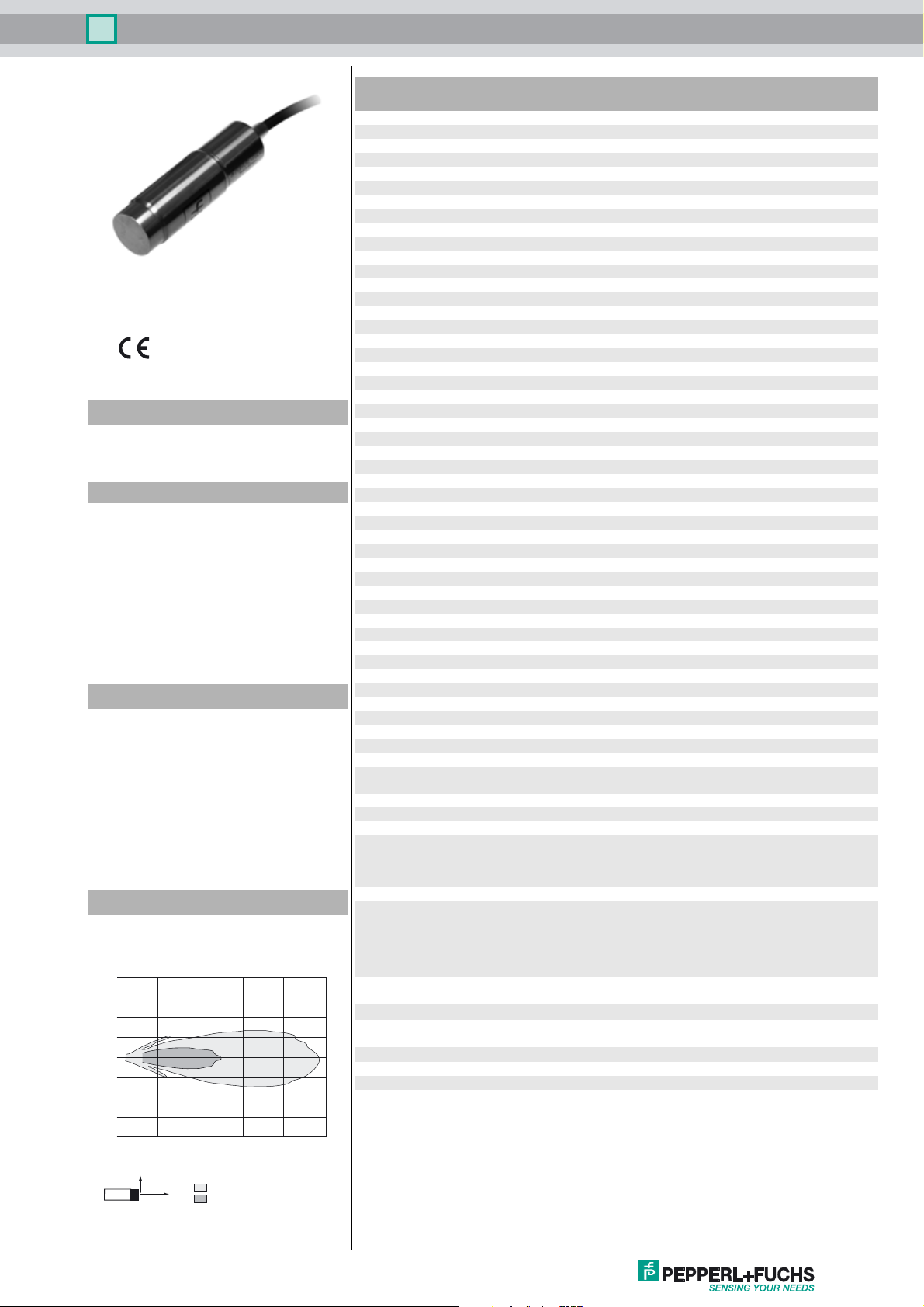
Diagrams
Characteristic response curve
Distance Y [m]
2.0
1.5
1.0
0.5
0.0
-0.5
-1.0
-1.5
-2.0
0 1 2 3 4 5
Y
flat surface 100 mm x 100 mm
X
round bar, Ø 25 mm
Distance X [m]
Operating voltage U
No-load supply current I
Input/Output
Input/output type 1 synchronization connection, bidirectional
0 Level 0 ... 1 V
1 Level 4 V ... U
Input impedance > 12 kΩ
Output rated operating current < 12 mA
Pulse length ≥ 200 µs
Pulse interval ≥ 2 ms
Synchronization frequency
Common mode operation ≤ 20 Hz
Multiplex operation ≤ 20/n Hz, n = number of sensors n ≤ 10 (factory setting: 5 )
Input
Input type 1 program input
Level (switch point 1) 0 ... 1 V
Level (switch point 2) 4 V ... U
Input impedance > 10 kΩ
Pulse length 2 ... 5 s
Output
Output type 1 switching output E5, PNP NO/NC, programmable
Rated operating current I
Voltage drop U
Repeat accuracy ≤ 0.1 % of full-scale value
Switching frequency f ≤ 2.8 Hz
Range hysteresis H programmable , preset to 1 mm
Temperature influence < 1.5 % of full-scale value
Ambient conditions
Ambient temperature -25 ... 60 °C (-13 ... 140 °F)
Storage temperature -40 ... 85 °C (-40 ... 185 °F)
Mechanical specifications
Connection type cable PUR , 5 m , With FDA approval
Core cross-section 5 x 0.5 mm
Degree of protection IP68 / IP69K
Material
Housing stainless steel 1.4404 / AISI 316L
Transducer Stainless steel 1.4435 / AISI 316L
Mass 425 g
Factory settings
Output near switch point: 240 mm
General information
Supplementary information Switch settings of the external programming adapter:
Compliance with standards and
directives
Standard conformity
Standards EN 60947-5-2:2007+A1:2012
Approvals and certificates
CCC approval CCC approval / marking not required for products rated ≤36 V
EHEDG Type EL Class I AUX
ECOLAB yes
B
0
e
d
10 ... 30 V DC
≤ 50 mA
B
B
200 mA , short-circuit/overload protected
≤ 2 V
2
LED window: VMQ Elastosil LR 3003/Shore 50 A
far switch point: 3000 mm
output function: Window mode
output behavior: NO contact
"output load": pull-down
"output logic": inv
FDA: All materials used for the sensor comply with CFR, title
21, §177.2600 (FDA)
IEC 60947-5-2:2007 + A1:2012
Release date: 2016-03-01 11:55 Date of issue: 2017-03-21 217778_eng.xml
Refer to “General Notes Relating to Pepperl+Fuchs Product Information”.
1
Page 2
Ultrasonic sensor UMC3000-30H-E5-5M-FA
Dimensions
ø 28
ø 30
11 3.5
Electrical Connection
100
BN
WH
GY
BK
BU
3.5 11
+U
B
Program input
Syncronization
Output
-U
B
ø 6.3
Additional Information
Programmable output modes
1. Window mode, normally open mode
A1 < A2:
A1
2. Window mode, normally closed mode
A2 < A1:
A2
3. One switch point, normally open mode
A1 -> ∞:
A2
4. One switch point, normally closed mode
A2 -> ∞:
A1
5. A1 -> ∞, A2 -> ∞: Object presence detection mode
Object detected: Switch output closed
No object detected: Switch output open
object distance
A2
A1
Accessories
V15S-G-0,3M-PUR-WAGO
Male cordset, M12, 5-pin, PUR cable with WAGO terminals
MH-30H-01-FA
Mounting aid, 30 mm acc. to EHEDG
UC-PROG1-USB
Programming adapter
Mounting
Comply with the minimum permissible bending radius of 70 mm, if you install the connecting
cable!
For reliable operation, you must use the included sensor mounting aid. This also applies for applications without special hygiene requirements.
Cleaning the Sensor in Areas with Hygiene Requirements
The sensor may only be used with the mounting aid included in the scope of delivery
as the fixture. Please note the information in the enclosed package insert for the
mounting aid with regard to the correct position of the seals and the correct process
for tightening the screw connections.
If the sensor as a whole is located in an area subject to hygiene requirements, the
sensor must be accessible from all sides for cleaning purposes. If the sensor is fitted
with only the front in an area subject to hygiene requirements, the front must be accessible from all sides accordingly.
The sensor and corresponding fixture are certified by ECOLAB. The components
were subjected to the cleaning agents listed in the certificate and are resistant to these agents. Use of other cleaning agents and chemicals is also possible. However, to
ensure the sensor and fixture offer resistance to these substances, corresponding
tests must be performed by the user.
For cleaning purposes, as a general rule you can completely cover the sensor including the fixture with foam and clean using a water jet. Cleaning at elevated temperatures of up to 85 °C is possible. It is not permitted to use high-pressure cleaning
equipment for cleaning purposes in areas subject to hygiene requirements.
Refer to “General Notes Relating to Pepperl+Fuchs Product Information”.
2
Release date: 2016-03-01 11:55 Date of issue: 2017-03-21 217778_eng.xml
Page 3

Ultrasonic sensor UMC3000-30H-E5-5M-FA
Programming
The sensor can be adapted to the specific requirements of the application by means of programming. There are two methods of programming.
1. Basic functions can be set using the teach-in process. These are the position of the switch points and the output function. The teach-in process is connected either with +U
level).
2. With a programming adapter (see Accessories) and the DTM module for PACTware, a comprehensive range of parameterisable functions is available. A male cordset with WAGO terminals
is needed for the connection to the programming adapter (see Accessories).
Note:
- The programming options are available in the first 5 minutes after switching on and are extended during programming. After 5 minutes without any programming activity, the sensor is locked to
prevent programming.
- It is possible to exit programming without changing the sensor settings at any time. Simply stop any programming activity. After 10 seconds, the sensor exits programming mode and switches
to normal operating mode with the last valid settings.
Programming the switch points
Note:
A flashing red LED during the programming process indicates unreliable object detection. In this case, adjust the alignment of the object until the yellow LED flashes. Only then are the settings stored
in the memory of the sensor.
Teach-in of A1 switch point
1. Position the target object at the desired switch point A1
2. Connect the teach-in for > 2 sec with +U
3. Disconnect the teach-in process. The yellow LED begins to flash after 2 secs and the sensor is ready for teach-in*).
4. Connect the teach-in process within 8 secs for > 2 sec with -UB.
5. Disconnect the teach-in process within 8 secs. The green LED flashes three times briefly for confirmation. The switch point A1 has now been taught in.
or -U
B
B
Teach-in of switch point A2
1. Position the target object at the desired switch point A2
2. Connect the teach-in for > 2 sec with +U
3. Disconnect the teach-in process. The yellow LED begins to flash after 2 secs and the sensor is ready for teach-in*).
4. Connect the teach-in process within 8 secs for > 2 sec with +UB.
5. Disconnect the teach-in process within 8 secs. The green LED flashes three times briefly for confirmation. The switch point A2 has now been taught in.
*)
If there are no objects within the sensor detection range while the sensor is ready for teach-in, this is indicated by fast flashing of the yellow LED. Teach-in is possible, however. In programming
switch point A1, this is set to the end of the blind zone. In programming switch point A2, this is set to the detection range upper limit.
or -U
B
B
Programming the output function
You can choose between NC and NO function for the output function of the sensor. The position of the programmed switch points is critical here.
If switch point A1 is closer to the sensor than A2, the switching output operates as NO.”
If switch point A2 is closer to the sensor than A1, the switching output operates as NC.
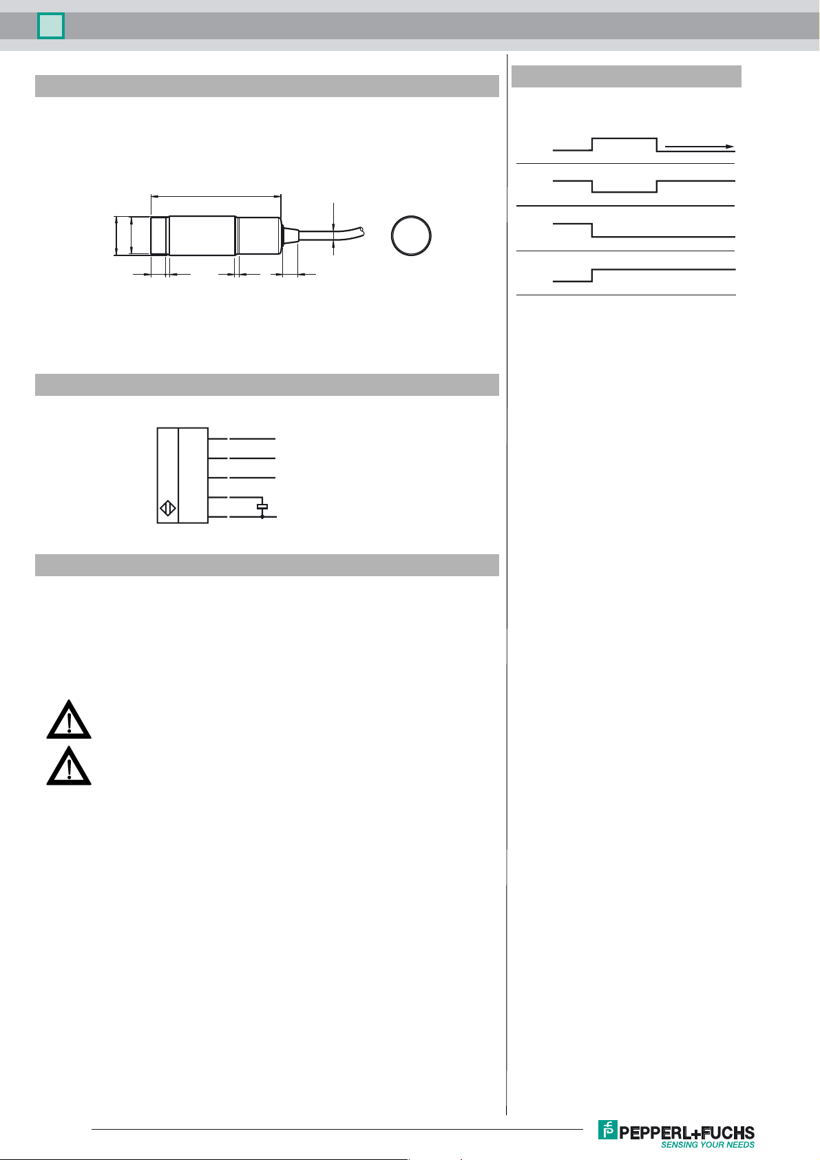
LED indicators
The sensor has 3 display LEDs to indicate various operating modes
Operating state Green LED Yellow LED Red LED
Normal operation lights up Object in evaluation
Programming the trip points
Object reliably detected
Unreliable object
Confirmation for successful programming
Off
Off
Flashes 3x
range
Flashes
Off
Off
Unreliable object
Off
Flashes
Off
(1 level) or -UB (0
B
Synchronisation
The sensor has a synchronisation input for suppressing mutual interefence by third-party ultrasonic signals. If this input is not connected, the sensor works with internally
generated clock pulses. It can be synchronised by connecting external rectangular pulses and through corresponding parameterisation via the DTM module for PACTware
Each falling pulse edge triggers the sending of an individual ultrasonic pulse. If the signal at the synchronisation input carries ≥ 1 s low level, the sensor returns to normal,
unsynchronised operating mode. This is also the case when the synchronisation input is disconnected from external signals (see note below).
If there is a high level > 1 s at the synchronisation input, the sensor enters standby mode. This is indicated by the flashing green LED. In this operating mode, the most recent
output statuses are retained. For external synchronisation, please observe the software description.
Note:
• If the synchronisation option is not being used, the synchronisation input must be earthed (0 V).
• The synchronisation option is not available during programming, which means that the sensor cannot be programmed during synchronisation.
The following synchronisation methods are possible:
1. Multiple sensors (for max. number see Technical data) can be synchronised by simply connecting their synchronisation inputs. In this case, the sensors operate in a selfsynchronised sequence in multiplex mode. Only one sensor transmits at any given time (see note below).
2. Multiple sensors (for max. number see Technical data) can be synchronised by simply connecting their synchronisation inputs. As a result of parameterisation via the DTM
module for PACTware
i.e. simultaneously in master/slave mode, whereby the master sensor performs the role of an intelligent external clock pulse generator.
3. Multiple sensors can be triggered jointly by an external signal. In this case, the sensors are triggered in parallel and operate synchronously, i.e. simultaneously. All sensors
must be parameterised for external control by means of parameterisation via the DTM module for PACTware
4. Multiple sensors are triggered with a delay by an external signal. In this case, only one sensor operates with external synchronisation at any given time (see note below).
All sensors must be parameterised for external control by means of parameterisation via the DTM module for PACTware
5. A high level (+U
Note:
The response time of the sensors increases proportionally to the number of sensors in the synchronisation chain. Multiplexing means that the measurement cycles of the
individual sensors run one after the other.
Note:
The synchronisation connection of the sensors delivers an output current at low level and an input impedance at high level. Please note that the synchronising device must
have the following drive capability:
Drive current with +U
Drive current with 0 V: ≥ n * output current (n = number of sensors to be synchronised)
TM
, one of the sensors operates as a master and the others as slaves (see Interface description). In this case, the sensors operate synchronously,
TM
(see Software description).
TM
(see Software description).
) or a low level (-UB) at the synchronisation input puts the sensor in standby mode in the case of external parameterisation.
B
: ≥ n * high level/input impedance (n = number of sensors to be synchronised)
B
TM
.
Release date: 2016-03-01 11:55 Date of issue: 2017-03-21 217778_eng.xml
Refer to “General Notes Relating to Pepperl+Fuchs Product Information”.
3
 Loading...