

Page 1
Product Data Sheet
SP4T FET Switch TGS8422-SCC
Key Features and Performance
• DC to18 GHz Frequency Range
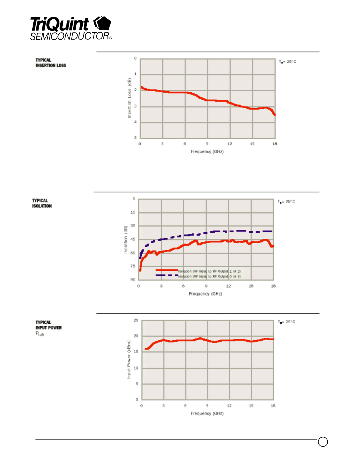
• 2.5 dB Insertion Loss at Midband
• 37 dB Isolation at Midband
• Typical Input Power of 19 dBm at
1 dB Gain Compression
• Typical SWR of 1.6:1
• 2.286 x 2.057 x 0.150 mm (0.090 x
0.081x 0.006 in.)
Description
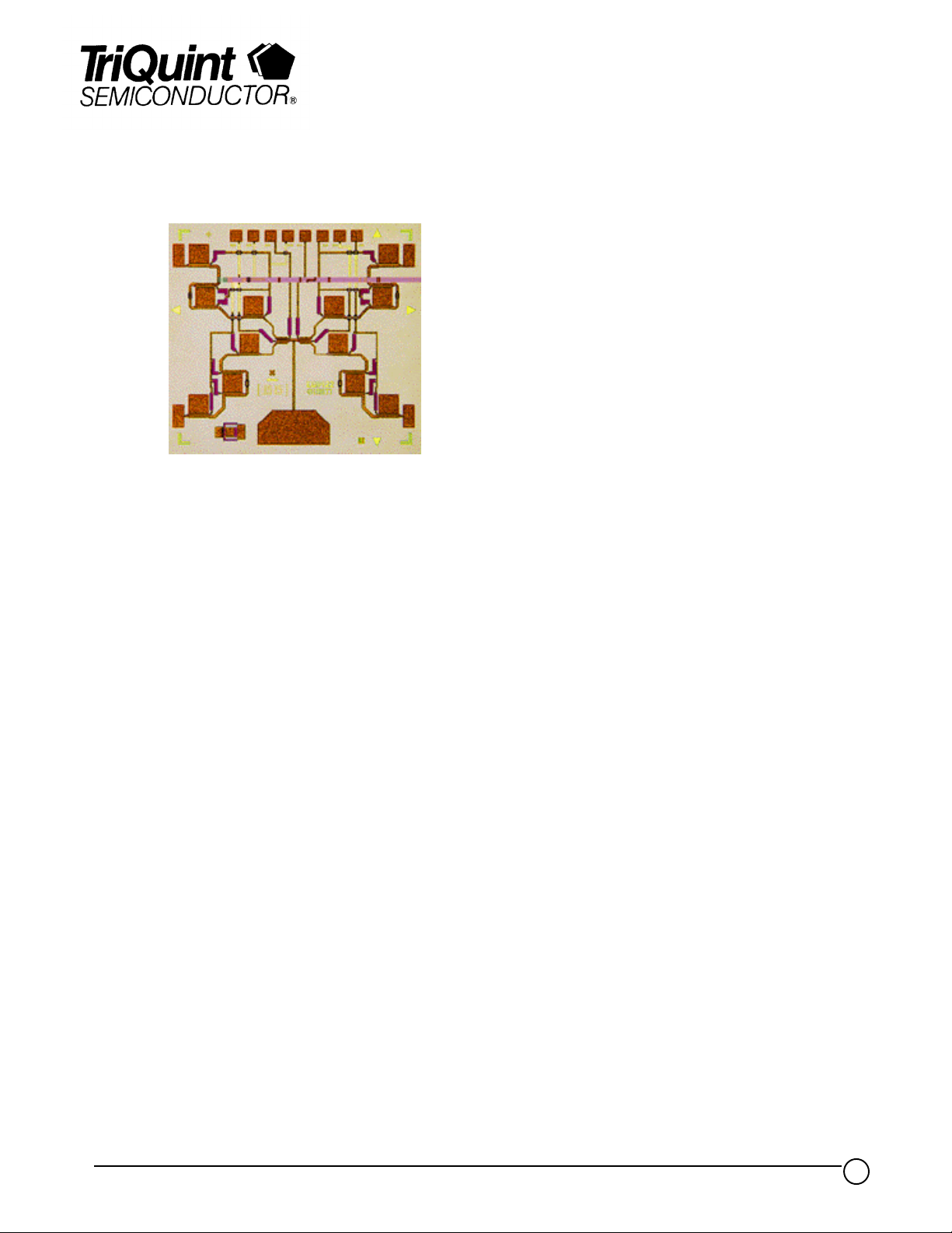
The TriQuint TGS8422-SCC is a GaAs MMIC SP4T FET switch which operates from
DC to 18 GHz. RF Output arm selection is made through 8 control lines. Control bias
voltages are 0 V and -5 V. Typical insertion loss is 2.5 dB at 9 GHz. Isolation is
typically 37 dB from RF Input to RF Outputs 0, 3 and 47 dB from RF Outputs 1 and 2.
The input and output return loss is typically
13 dB.
The reflective, single-pole, four-throw design utilizes one series and four shunt FETs in
each RF Output arm to produce a broadband, low-loss, high-isolation switch. The
monolithic construction simplifies the assembly process and makes this device useful
for electronic warfare, radar and telecommunication applications.
Bond pad and backside metallization is gold plated for compatibility with eutectic alloy
attachment methods as well as thermocompression and thermosonic wire-bonding
processes. Ground is provided to the circuitry through vias to the backside
metallization.
TriQuint Semiconductor Texas : (972)994 8465 Fax: (972)994 8504 Web: www.triquint.com
1
Page 2
Product Data Sheet
TGS8422-SCC
TriQuint Semiconductor Texas : (972)994 8465 Fax: (972)994 8504 Web: www.triquint.com
2
Page 3

Product Data Sheet
TGS8422-SCC
TriQuint Semiconductor Texas : (972)994 8465 Fax: (972)994 8504 Web: www.triquint.com
3
Page 4

Product Data Sheet
TGS8422-SCC
TYPICAL S-PARAMETERS
RF Input to RF Output 3
Frequency
(G Hz ) MAG ANG( °) MAG ANG( °) MAG ANG(°) MAG ANG(°) (d B)
S
11
S
21
S
12
S
22
Insertion Loss
0.5 0.18 - 3 0.805 - 9 0.806 - 8 0.17 - 1 1.9
1.0 0.18 - 13 0.801 - 16 0.802 - 15 0.17 - 5 1.9
2.0 0.20 - 30 0.797 - 30 0.798 - 30 0.17 - 21 2.0
3.0 0.21 - 44 0.790 - 45 0.791 - 45 0.17 - 38 2.0
4.0 0.22 - 51 0.784 - 59 0.785 - 59 0.16 - 45 2.1
5.0 0.22 - 56 0.784 - 74 0.786 - 74 0.15 - 53 2.1
6.0 0.18 - 78 0.791 - 89 0.793 - 89 0.14 - 87 2.0
7.0 0.21 - 124 0.776 - 106 0.778 - 106 0.14 - 141 2.2
8.0 0.26 - 139 0.749 - 121 0.751 - 121 0.13 - 162 2.5
9.0 0.25 - 132 0.742 - 135 0.743 - 135 0.12 - 146 2.6
10.0 0.20 - 131 0.746 - 150 0.746 - 150 0.14 - 148 2.5
11.0 0.22 - 167 0.747 - 166 0.748 - 166 0.10 164 2.5
12.0 0.27 161 0.721 178 0.723 178 0.14 112 2.8
13.0 0.25 151 0.706 163 0.707 163 0.18 119 3.0
14.0 0.21 162 0.700 148 0.702 148 0.18 137 3.1
15.0 0.26 170 0.697 134 0.698 134 0.17 156 3.1
16.0 0.28 159 0.707 118 0.709 119 0.14 156 3.0
17.0 0.19 137 0.709 101 0.708 101 0.17 110 3.0
18.0 0.18 115 0.673 83 0.674 83 0.24 93 3.4
TA = 25oC
TYPICAL S-PARAMETERS
RF Input to RF Output 2
Frequency
(G Hz ) MAG ANG( °) MAG ANG(°) MAG ANG(°) MAG ANG (°) (d B)
S
11
S
21
S
12
S
22
Insertion Loss
0.5 0.18 - 3 0.803 - 9 0.804 - 9 0.17 1 1.9
1.0 0.18 - 12 0.798 - 16 0.800 - 16 0.18 5 2.0
2.0 0.19 - 27 0.794 - 32 0.796 - 31 0.18 18 2.0
3.0 0.21 - 40 0.788 - 47 0.789 - 47 0.17 31 2.1
4.0 0.23 - 49 0.784 - 62 0.785 - 62 0.15 40 2.1
5.0 0.21 - 56 0.783 - 78 0.785 - 77 0.15 60 2.1
6.0 0.14 - 71 0.783 - 93 0.785 - 93 0.19 90 2.1
7.0 0.16 - 110 0.774 - 110 0.776 - 109 0.15 110 2.2
8.0 0.25 - 128 0.753 - 125 0.755 - 125 0.07 126 2.5
9.0 0.25 - 125 0.738 - 140 0.739 - 140 0.09 140 2.6
10.0 0.19 - 118 0.739 - 155 0.738 - 155 0.18 146 2.6
11.0 0.19 - 146 0.735 - 171 0.738 - 171 0.13 164 2.7
12.0 0.25 177 0.725 173 0.727 173 0.07 145 2.8
13.0 0.23 169 0.712 157 0.713 158 0.10 148 3.0
14.0 0.25 - 179 0.704 142 0.706 142 0.16 169 3.0
15.0 0.30 179 0.695 127 0.695 127 0.19 174 3.2
16.0 0.31 170 0.697 111 0.701 111 0.18 158 3.1
17.0 0.25 160 0.698 93 0.694 94 0.25 129 3.1
18.0 0.28 133 0.664 75 0.665 76 0.27 125 3.6
= 25oC
T
A
Reference planes for S-parameter data include bond wires as specified in “Recommended Bias
Network”.
TriQuint Semiconductor Texas : (972)994 8465 Fax: (972)994 8504 Web: www.triquint.com
4
Page 5

Product Data Sheet
TGS8422-SCC
RF CHARACTERISTICS
TRUTH TABLE
EQUIVALENT SCHEMATIC
PARAMETER TEST CONDITIONS TYP UNIT
IL Insertion loss midband 2.5 dB
ISO Isolation midband 37 dB
SWR(in) Input standing wave ratio 1.6:1 -
SWR(out) Output standing wave ratio through s elected output arm 1.3:1 -
(in )
P
1dB
Input power at 1dB gain compression 19 dBm
S ele cte d CO NT R OL VO LT AGES (VOLT S )
RF Output
V
1
V
2
V
3
V
4
V
5
V
6
V
7
V
8
RF Output 00-5-50-50-50
RF Output 1-50-50 0-5-50
RF Output 2-50 0-5-50-50
RF Output 3-50-50-50 0-5
TriQuint Semiconductor Texas : (972)994 8465 Fax: (972)994 8504 Web: www.triquint.com
5
Page 6

Product Data Sheet
TGS8422-SCC
RECOMMENDED BIAS
NETWORK
________________________________________________________________________________________
V1V2V3V4V5V6V7V
8
4 5 6 7 8 9 10 11
12
RF Output 1
RF Output 2
3
TGS8422
RF Output 0
2
1
RF Input
13
RF Output 3
Refer to TriQuint Gallium Arsenide Products Designers’ Information on TriQuint’s web site.
GaAs MMIC devices are susceptible to damage from Electrostatic Discharge. Proper precautions should be observed during
handling, assembly and test.
TriQuint Semiconductor Texas : (972)994 8465 Fax: (972)994 8504 Web: www.triquint.com
6
 Loading...