

Page 1
Product Data Sheet
SPDT FET Switch TGS8250-SCC
Key Features and Performance
• DC to 18 GHz Frequency Range
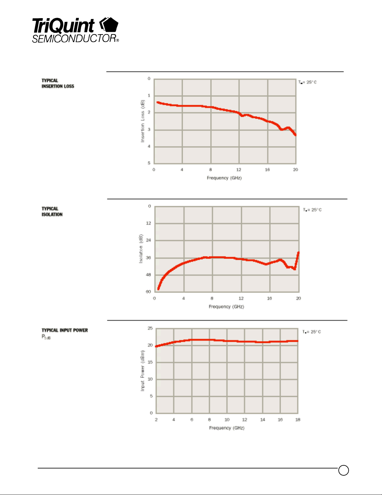
• 2 dB Typical Insertion Loss
• 39 dB Typical Isolation Across Band
• 2 ns Rise/Fall Time
• 50 uA Typical Current Consumption with
Control Voltage of -7 V, 0 V
• 1.8034 x 1.2700 x 0.1016 mm (0.071 x
0.050 x 0.004 in.)
Description
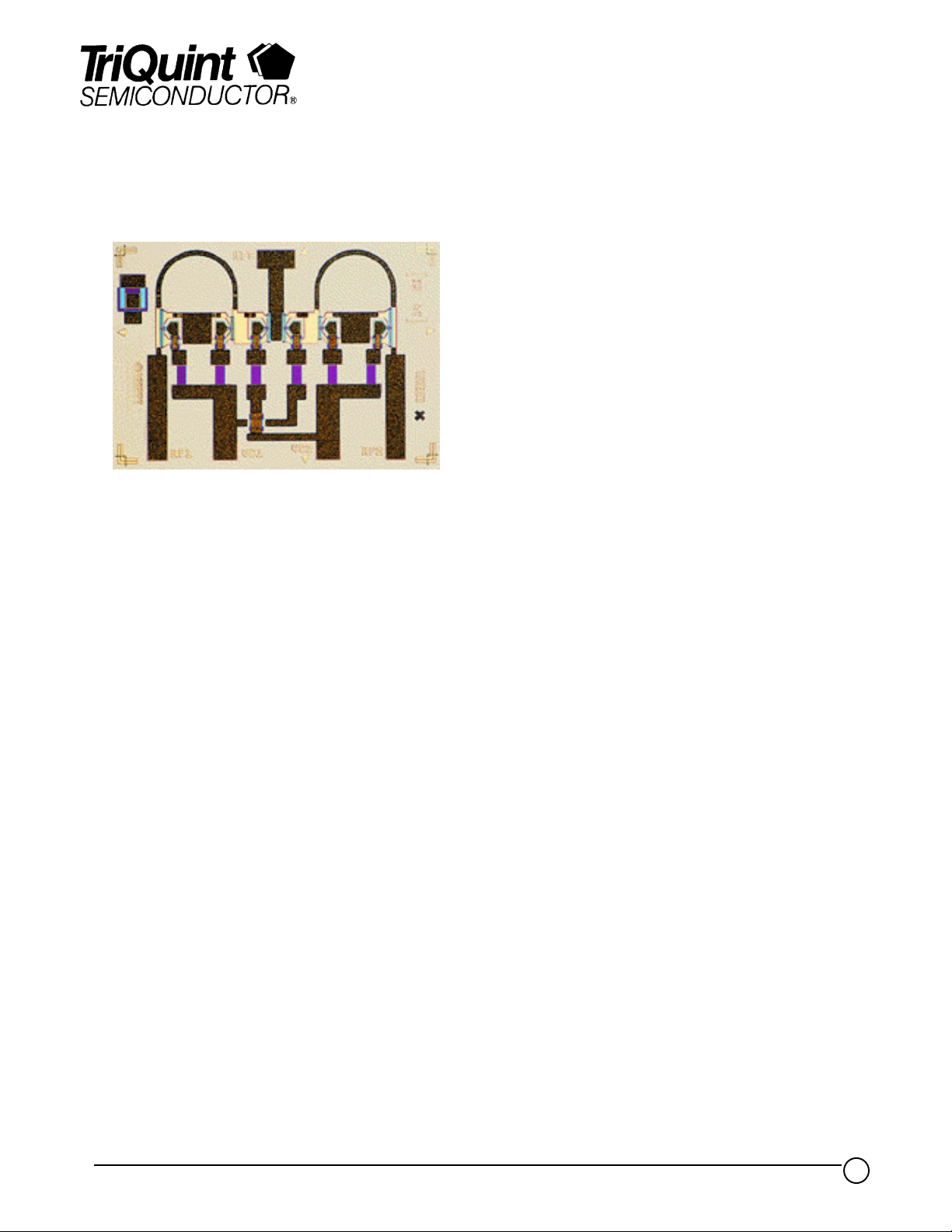
The TriQuint TGS8250-SCC is a GaAs single-pole, double-throw (SPDT) FET
monolithic switch designed to operate over the DC to 18 GHz frequency range.
This switch not only maintains a high isolation loss and a low insertion loss across a
wide bandwidth, but also has very low power consumption and
attains a rise/fall time of less than 2 ns. These advantages, along with the small size
of the chip, make the TGS8250-SCC ideal for use in high-speed
radar and communication applications.
Bond pad and backside metallization are gold plated for compatibility with eutectic
alloy attachment methods as well as the thermocompression and thermosonic wire
bonding processes.
The TGS8250-SCC is supplied in chip form and is engineered for high-volume
automated assembly.
TriQuint Semiconductor Texas : (972)994 8465 Fax: (972)994 8504 Web: www.triquint.com
1
Page 2
Product Data Sheet
TGS8250-SCC
TriQuint Semiconductor Texas : (972)994 8465 Fax: (972)994 8504 Web: www.triquint.com
2
Page 3
Product Data Sheet
TGS8250-SCC
TriQuint Semiconductor Texas : (972)994 8465 Fax: (972)994 8504 Web: www.triquint.com
3
Page 4

Product Data Sheet
TGS8250-SCC
TYPICAL S-PARAMETERS
Insertion Path
Frequency
(G Hz) MAG ANG( °) MAG ANG(°) MAG ANG(°) MAG ANG(°) (d B)
S
11
S
21
S
12
S
22
Insertion Loss
0.5 0.13 - 4 0.85 - 6 0.855 - 6 0.12 - 8 1.4
1.0 0.12 - 4 0.85 - 12 0.850 - 11 0.12 - 12 1.5
1.5 0.12 - 4 0.84 - 17 0.844 - 17 0.11 - 16 1.5
2.0 0.13 - 5 0.84 - 22 0.840 - 22 0.10 - 19 1.5
2.5 0.13 - 7 0.84 - 28 0.839 - 27 0.09 - 23 1.5
3.0 0.13 - 10 0.84 - 33 0.837 - 32 0.09 - 28 1.6
3.5 0.14 - 13 0.83 - 39 0.837 - 38 0.08 - 33 1.6
4.0 0.15 - 18 0.83 - 44 0.835 - 43 0.07 - 42 1.6
4.5 0.15 - 23 0.83 - 50 0.834 - 49 0.06 - 51 1.6
5.0 0.16 - 29 0.83 - 55 0.834 - 54 0.05 - 65 1.6
5.5 0.16 - 35 0.83 - 61 0.835 - 60 0.05 - 85 1.6
6.0 0.17 - 42 0.83 - 66 0.833 - 65 0.04 - 112 1.6
6.5 0.17 - 50 0.83 - 72 0.830 - 71 0.04 - 135 1.6
7.0 0.17 - 58 0.83 - 78 0.830 - 77 0.06 - 155 1.6
7.5 0.17 - 66 0.83 - 84 0.830 - 82 0.08 - 175 1.7
8.0 0.17 - 74 0.83 - 89 0.827 - 88 0.09 171 1.7
8.5 0.18 - 83 0.82 - 95 0.824 - 94 0.11 158 1.7
9.0 0.18 - 92 0.82 - 101 0.820 - 100 0.13 149 1.8
9.5 0.18 - 101 0.81 -107 0.814 - 105 0.15 142 1.8
10.0 0.18 - 109 0.81 - 112 0.807 - 111 0.17 134 1.9
10.5 0.18 - 115 0.81 - 118 0.808 - 116 0.18 127 1.9
11.0 0.19 - 125 0.80 - 124 0.808 - 122 0.20 122 1.9
11.5 0.19 - 134 0.80 - 129 0.801 - 127 0.22 116 2.0
12.0 0.19 - 143 0.79 - 135 0.793 - 133 0.23 111 2.0
12.5 0.20 - 151 0.79 - 140 0.789 - 138 0.25 106 2.1
13.0 0.20 - 159 0.78 - 146 0.787 - 144 0.27 101 2.1
13.5 0.21 - 168 0.78 - 151 0.779 - 149 0.28 96 2.2
14.0 0.21 - 177 0.77 - 157 0.769 - 154 0.29 93 2.3
14.5 0.21 175 0.77 - 162 0.771 - 159 0.31 88 2.3
15.0 0.22 167 0.76 - 167 0.768 - 165 0.33 83 2.3
15.5 0.24 158 0.76 - 173 0.757 - 171 0.34 79 2.4
16.0 0.24 151 0.75 - 179 0.747 - 176 0.34 75 2.5
16.5 0.25 143 0.75 176 0.744 178 0.35 71 2.6
17.0 0.26 135 0.74 170 0.742 172 0.36 68 2.6
17.5 0.27 131 0.73 163 0.732 166 0.37 63 2.7
18.0 0.29 124 0.71 158 0.708 161 0.36 60 3.0
18.5 0.30 118 0.71 152 0.718 155 0.37 53 3.0
19.0 0.31 112 0.72 145 0.721 148 0.37 46 2.9
19.5 0.31 108 0.71 138 0.709 140 0.37 37 3.0
20.0 0.32 108 0.68 131 0.679 134 0.34 25 3.3
20.5 0.36 106 0.68 125 0.687 127 0.30 15 3.3
= 250C
T
A
Reference planes for S-parameter data include bond wires as specified in the “Recommended Assembly
Diagram”. The S-parameters are also available on floppy disk and the world wide web.
TriQuint Semiconductor Texas : (972)994 8465 Fax: (972)994 8504 Web: www.triquint.com
4
Page 5

Product Data Sheet
TGS8250-SCC
TYPICAL S-PARAMETERS
Isolation Path
Frequency
(G Hz) MAG ANG( °) MAG ANG( °) MAG ANG( °) MAG ANG( °) ( dB )
S
11
S
21
S
12
S
22
0.5 0.15 1 0.001 92 0.001 92 0.74 175 58.4
1.0 0.15 - 1 0.002 89 0.002 89 0.74 170 52.0
1.5 0.16 - 1 0.004 89 0.004 89 0.74 165 48.6
2.0 0.17 - 4 0.005 87 0.005 88 0.73 160 45.9
2.5 0.18 - 7 0.006 85 0.006 86 0.73 155 44.2
3.0 0.19 - 12 0.007 84 0.007 84 0.73 150 42.5
3.5 0.20 - 17 0.009 83 0.009 84 0.73 146 41.3
4.0 0.21 - 23 0.010 82 0.010 82 0.73 141 40.2
4.5 0.22 - 31 0.011 80 0.011 81 0.72 136 39.2
5.0 0.23 - 38 0.012 78 0.012 78 0.72 132 38.3
5.5 0.24 - 45 0.013 76 0.013 77 0.72 128 37.7
6.0 0.25 - 54 0.014 73 0.014 74 0.71 124 37.1
6.5 0.27 - 64 0.015 71 0.015 72 0.70 120 36.5
7.0 0.27 - 74 0.017 66 0.016 67 0.70 117 35.7
7.5 0.27 - 84 0.016 60 0.016 62 0.71 114 36.0
8.0 0.28 - 92 0.016 58 0.016 60 0.72 110 35.8
8.5 0.29 - 102 0.016 55 0.017 56 0.71 105 35.7
9.0 0.30 - 112 0.016 50 0.016 51 0.69 102 35.8
9.5 0.30 - 123 0.016 47 0.016 48 0.69 101 35.9
10.0 0.29 - 132 0.016 41 0.016 44 0.70 99 36.0
10.5 0.30 - 140 0.015 39 0.015 41 0.71 95 36.3
11.0 0.31 - 150 0.015 31 0.015 32 0.70 92 36.3
11.5 0.31 - 160 0.014 23 0.015 24 0.69 90 36.8
12.0 0.31 - 170 0.014 18 0.014 19 0.69 89 37.2
12.5 0.31 - 179 0.013 11 0.013 13 0.69 87 37.7
13.0 0.31 171 0.013 4 0.013 5 0.70 84 37.9
13.5 0.31 161 0.013 - 6 0.013 - 4 0.70 83 37.9
14.0 0.31 150 0.012 - 17 0.012 - 14 0.70 82 38.5
14.5 0.30 141 0.011 - 25 0.011 - 23 0.72 81 39.2
15.0 0.30 131 0.010 - 31 0.010 - 29 0.73 78 39.8
15.5 0.29 121 0.009 - 32 0.009 - 30 0.71 76 40.7
16.0 0.29 111 0.010 - 30 0.010 - 28 0.70 76 39.9
16.5 0.28 101 0.011 - 36 0.011 - 34 0.70 76 39.0
17.0 0.26 90 0.011 - 40 0.012 - 37 0.72 76 38.8
17.5 0.24 81 0.013 - 43 0.013 - 42 0.73 73 37.5
18.0 0.22 73 0.011 - 103 0.011 - 101 0.71 74 38.9
18.5 0.20 62 0.007 - 29 0.007 - 26 0.74 72 43.1
19.0 0.15 46 0.007 - 26 0.007 - 22 0.77 70 42.7
19.5 0.08 23 0.006 47 0.006 49 0.78 64 44.2
20.0 0.06 - 135 0.024 13 0.024 15 0.75 61 32.5
20.5 0.17 166 0.033 - 18 0.033 - 15 0.73 58 29.7
Isolatio n
= 250C
T
A
Reference planes for S-parameter data include bond wires as specified in the “Recommended
Assembly Diagram”. The S-parameters are also available on floppy disk and the world wide web.
TriQuint Semiconductor Texas : (972)994 8465 Fax: (972)994 8504 Web: www.triquint.com
5
Page 6

Product Data Sheet
TGS8250-SCC
RF CHARACTERISTICS
PARAMETER TEST CONDITIONS TYP UNIT
IL Insertion los s f = DC to 18 GHz 2 d B
ISO Isolat ion f = DC to 18 GHz 39 dB
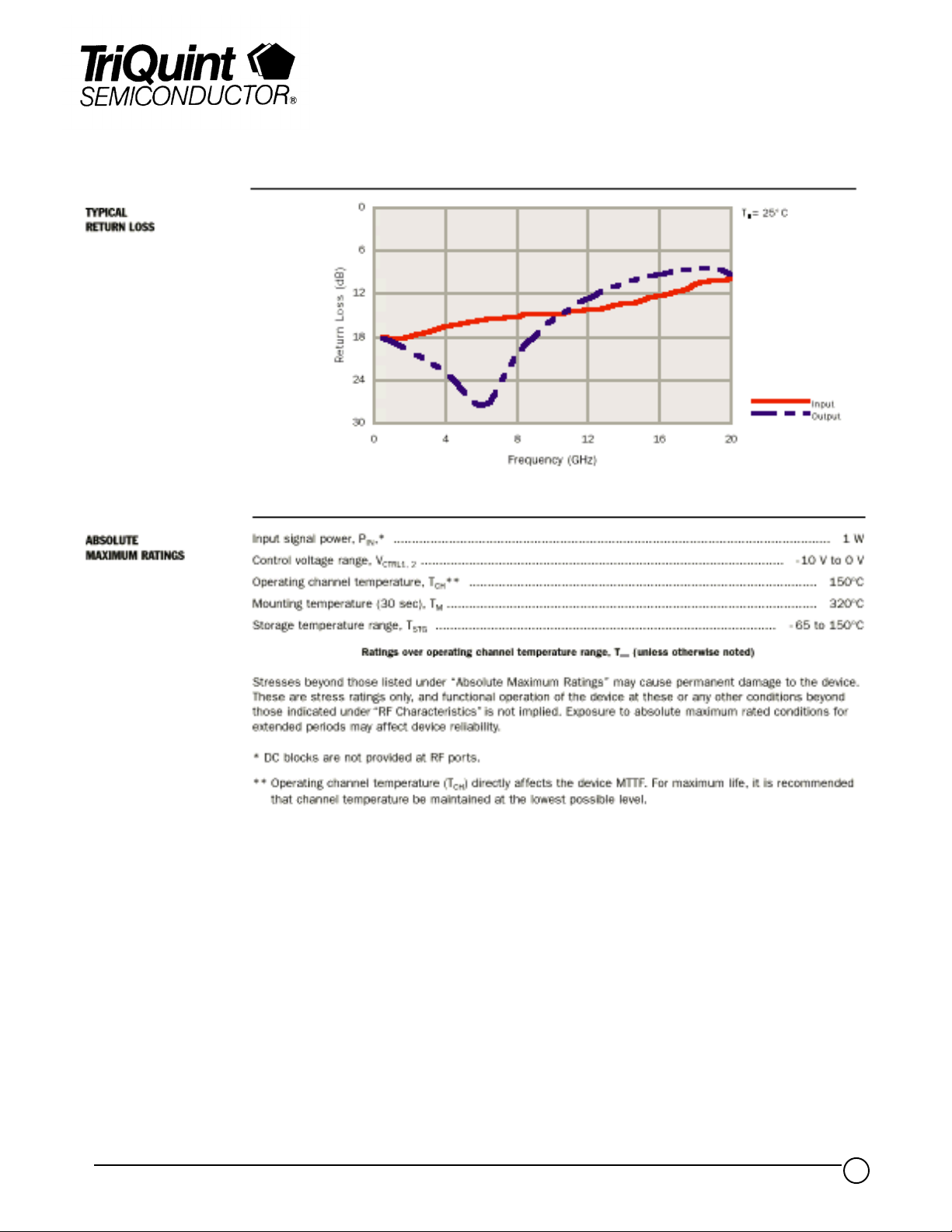
SWR(in) Input standing–wave ratio f = DC to 18 GHz 1.5:1 —
SWR(out) Output standing–wave ratio f = DC to 18 GHz 1.5:1 —
(in )
P
1dB
t
r
t
f
Input power at 1–dB gain compression f = 2 to 18 GHz 21 dBm
= 8 dBm, f = 10 GHz
P
Ris e t im e
Fall time
IN
<2 ns
TriQuint Semiconductor Texas : (972)994 8465 Fax: (972)994 8504 Web: www.triquint.com
6
Page 7

Product Data Sheet
TGS8250-SCC
GaAs MMIC devices are susceptible to damage from Electrostatic Discharge. Proper precautions should be observed during
handling, assembly and test.
TriQuint Semiconductor Texas : (972)994 8465 Fax: (972)994 8504 Web: www.triquint.com
7
 Loading...