

Page 1
Product Data Sheet
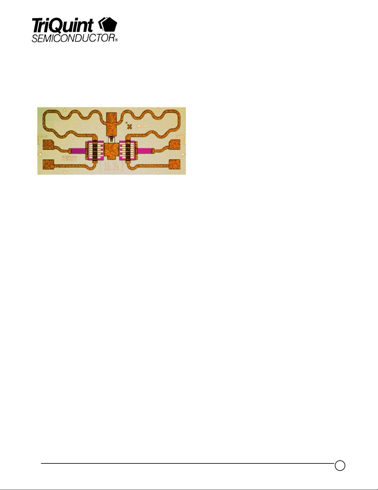
SPDT FET Switch TGS8122-SCC
Key Features and Performance
• 8 to 11 GHz Frequency Range
• 0.9 dB Typical Insertion Loss
• 40 dB Typical Isolation at 9 GHz
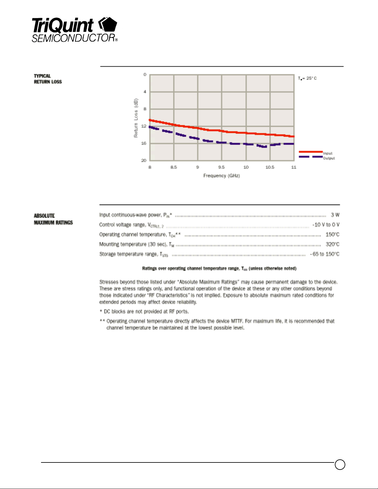
• 1.5:1 Typical Input SWR at Midband
• 1.4:1 Typical Output SWR at Midband
• Less Than 2 ns Rise/Fall Time
• 1.7018 x 0.7112 x 0.152 mm (0.067 x
0.028 x 0.006 in.)
Description
The TriQuint TGS8122-SCC is a monolithic single-pole, double-throw (SPDT) GaAs
FET switch designed for 8 to 11 GHz. This device has low insertion loss, low current
consumption of less than 50 mA with control voltages of -7 V and 0 V, and rise and fall
times are less than 2 ns. Ground is provided to the circuitry through vias to the
backside metallization.
This switch is ideal for use in high-speed switching radar and communication systems.
Bond pad and backside metallization is gold plated for compatibility with eutectic alloy
attachment methods as well as the thermocompression and thermosonic wire-bonding
processes.
The TGS8122-SCC is supplied in chip form and is readily assembled using automated
equipment.
TriQuint Semiconductor Texas : (972)994 8465 Fax: (972)994 8504 Web: www.triquint.com
1
Page 2

Product Data Sheet
TGS8122-SCC
TriQuint Semiconductor Texas : (972)994 8465 Fax: (972)994 8504 Web: www.triquint.com
2
Page 3
Product Data Sheet
TGS8122-SCC
TriQuint Semiconductor Texas : (972)994 8465 Fax: (972)994 8504 Web: www.triquint.com
3
Page 4

TYPICAL S-PARAMETERS
Insertion Path
Product Data Sheet
TGS8122-SCC
Frequency
(G Hz) MAG ANG( °) MAG ANG( °) MAG ANG(°) MAG ANG(°) (d B)
7.0 0.30 106 0.88 - 73 0.876 -73 0.25 - 53 1.2
7.1 0.29 106 0.88 - 75 0.880 -75 0.24 - 57 1.1
7.2 0.28 106 0.88 - 77 0.882 -77 0.23 - 61 1.1
7.3 0.27 106 0.88 - 79 0.885 -79 0.22 - 66 1.1
7.4 0.27 106 0.89 - 81 0.886 -81 0.22 - 71 1.0
7.5 0.26 107 0.89 - 83 0.887 -83 0.21 - 76 1.0
7.6 0.26 108 0.89 - 85 0.888 -85 0.20 - 81 1.0
7.7 0.25 108 0.89 - 87 0.890 -87 0.20 - 86 1.0
7.8 0.25 109 0.90 - 89 0.891 -89 0.19 - 91 1.0
7.9 0.24 110 0.90 - 91 0.893 -91 0.19 - 96 0.9
8.0 0.24 110 0.90 - 93 0.894 -93 0.18 - 101 1.0
8.1 0.23 112 0.90 - 95 0.896 -95 0.18 - 106 0.9
8.2 0.23 112 0.90 - 97 0.897 -97 0.17 - 112 0.9
8.3 0.23 113 0.90 - 99 0.897 -99 0.17 - 118 0.9
8.4 0.22 114 0.90 - 101 0.898 -101 0.17 - 123 0.9
8.5 0.22 115 0.90 - 103 0.899 -103 0.16 - 129 0.9
8.6 0.22 117 0.90 - 105 0.899 -105 0.16 - 135 0.9
8.7 0.22 117 0.90 - 107 0.899 -107 0.16 - 140 0.9
8.8 0.21 118 0.90 - 109 0.902 -108 0.16 - 145 0.9
8.9 0.21 119 0.90 - 111 0.902 -110 0.16 - 151 0.9
9.0 0.21 120 0.90 - 112 0.903 -112 0.16 - 156 0.9
9.1 0.21 121 0.90 - 114 0.903 -114 0.16 - 162 0.9
9.2 0.21 122 0.90 - 116 0.903 -116 0.15 - 167 0.9
9.3 0.20 123 0.90 - 118 0.904 -118 0.15 - 172 0.9
9.4 0.20 123 0.90 - 120 0.904 -120 0.15 - 177 0.9
9.5 0.20 124 0.90 - 122 0.904 -122 0.15 179 0.9
9.6 0.20 124 0.90 - 124 0.904 -124 0.15 174 0.9
9.7 0.20 125 0.90 - 126 0.904 -126 0.16 170 0.9
9.8 0.20 125 0.90 - 128 0.904 -128 0.16 165 0.9
9.9 0.19 125 0.90 - 130 0.904 -130 0.16 160 0.9
10.0 0.19 126 0.90 - 132 0.902 - 132 0.16 156 0.9
10.1 0.19 127 0.90 - 134 0.902 - 134 0.15 152 0.9
10.2 0.19 128 0.90 - 136 0.901 - 136 0.15 148 0.9
10.3 0.18 128 0.90 - 138 0.902 - 138 0.15 144 0.9
10.4 0.18 128 0.90 - 140 0.901 - 140 0.15 141 0.9
10.5 0.18 129 0.90 - 142 0.899 - 142 0.15 137 0.9
10.6 0.17 130 0.90 - 144 0.898 - 144 0.15 133 0.9
10.7 0.17 132 0.90 - 147 0.898 - 146 0.15 129 0.9
S
11
10.8 0.17 133 0.90 - 149 0.895 - 148 0.15 125 1.0
10.9 0.17 134 0.90 - 151 0.896 - 151 0.14 120 1.0
11.0 0.16 135 0.89 - 153 0.895 - 153 0.14 115 1.0
11.1 0.16 137 0.89 - 155 0.893 - 155 0.14 110 1.0
11.2 0.16 140 0.89 - 157 0.892 - 157 0.13 105 1.0
11.3 0.15 142 0.89 - 159 0.891 - 159 0.13 100 1.0
11.4 0.15 146 0.89 - 161 0.887 - 161 0.12 94 1.0
11.5 0.15 149 0.88 - 163 0.885 - 163 0.12 89 1.1
11.6 0.16 152 0.88 - 165 0.883 - 165 0.11 83 1.1
11.7 0.16 154 0.88 - 167 0.882 - 167 0.11 77 1.1
11.8 0.17 156 0.88 - 169 0.881 - 169 0.10 69 1.1
11.9 0.17 157 0.88 - 171 0.878 - 171 0.09 62 1.1
12.0 0.17 158 0.88 - 173 0.878 - 173 0.09 55 1.1
Reference planes for S-parameter data include bond wires as specified in the “Recommended
Assembly Diagram”. The S-parameters are also available on floppy disk and the world wide web.
S
21
S
12
S
22
Insertion Loss
TA = 25oC
TriQuint Semiconductor Texas : (972)994 8465 Fax: (972)994 8504 Web: www.triquint.com
4
Page 5

TYPICAL S-PARAMETERS
Isolation Path
Product Data Sheet
TGS8122-SCC
Frequency
(G Hz) MAG ANG (°) MAG ANG (°) MAG ANG (°) MAG ANG( °) (d B)
S
11
S
21
7.0 0.17 85 0.053 - 84 0.055 - 85 0.89 122 25.5
7.1 0.16 86 0.053 - 87 0.052 - 87 0.90 121 25.5
7.2 0.14 88 0.049 - 89 0.050 - 88 0.89 120 26.2
7.3 0.13 92 0.050 - 88 0.049 - 91 0.90 120 26.0
7.4 0.11 96 0.045 - 95 0.046 - 93 0.90 119 26.9
7.5 0.10 103 0.045 - 96 0.044 - 96 0.90 118 26.9
7.6 0.09 112 0.041 - 101 0.042 - 97 0.90 118 27.7
7.7 0.09 122 0.036 - 100 0.040 - 100 0.90 117 28.9
7.8 0.09 133 0.037 - 100 0.038 - 103 0.90 116 28.6
7.9 0.09 141 0.039 - 106 0.035 - 104 0.90 115 28.2
8.0 0.10 151 0.032 - 100 0.032 - 108 0.90 114 29.9
8.1 0.10 158 0.030 - 107 0.030 - 109 0.90 114 30.5
8.2 0.12 163 0.029 - 114 0.028 - 110 0.90 113 30.8
8.3 0.13 167 0.025 - 116 0.025 - 114 0.90 112 32.0
8.4 0.14 169 0.021 - 114 0.023 - 117 0.90 111 33.6
8.5 0.15 171 0.019 - 120 0.020 - 117 0.90 111 34.4
8.6 0.17 173 0.020 - 114 0.017 - 120 0.90 110 34.0
8.7 0.19 173 0.015 - 114 0.015 - 120 0.90 109 36.5
8.8 0.20 173 0.014 - 116 0.012 - 122 0.90 108 37.1
8.9 0.21 173 0.012 - 122 0.011 - 126 0.90 108 38.4
9.0 0.23 172 0.009 - 115 0.008 - 127 0.90 107 40.9
9.1 0.24 171 0.006 - 121 0.007 - 117 0.90 106 44.4
9.2 0.25 170 0.004 - 74 0.004 - 112 0.89 105 49.0
9.3 0.27 169 0.004 - 117 0.002 - 93 0.90 105 48.0
9.4 0.28 168 0.001 23 0.001 - 65 0.90 104 58.9
9.5 0.29 166 0.002 10 0.002 18 0.90 103 54.0
9.6 0.30 165 0.004 1 0.004 13 0.89 103 48.5
9.7 0.31 164 0.004 14 0.007 22 0.90 102 48.0
9.8 0.32 162 0.008 21 0.009 28 0.90 101 42.4
9.9 0.33 160 0.013 28 0.010 26 0.89 100 37.7
10.0 0.33 159 0.012 22 0.013 23 0.89 100 38.4
10.1 0.34 157 0.016 27 0.015 21 0.90 99 35.9
10.2 0.35 155 0.017 19 0.017 18 0.90 98 35.4
10.3 0.35 153 0.020 16 0.018 17 0.90 98 34.0
10.4 0.36 152 0.020 12 0.020 16 0.89 97 34.0
10.5 0.36 151 0.020 10 0.021 13 0.90 96 34.0
10.6 0.37 149 0.023 9 0.024 11 0.89 95 32.8
10.7 0.37 147 0.025 9 0.025 8 0.88 95 32.0
10.8 0.38 145 0.028 6 0.027 7 0.89 95 30.9
10.9 0.38 144 0.031 6 0.030 5 0.89 94 30.2
11.0 0.38 142 0.030 2 0.031 2 0.89 93 30.5
11.1 0.38 140 0.033 - 1 0.033 - 1 0.89 92 29.6
11.2 0.38 138 0.036 - 5 0.035 - 5 0.89 91 28.9
11.3 0.38 136 0.036 - 4 0.037 - 7 0.89 91 28.9
11.4 0.38 134 0.039 - 13 0.038 - 9 0.89 90 28.2
11.5 0.37 132 0.042 - 12 0.041 - 12 0.88 90 27.5
11.6 0.37 130 0.043 - 13 0.042 - 15 0.88 89 27.3
11.7 0.37 128 0.043 - 16 0.044 - 19 0.88 88 27.3
11.8 0.36 125 0.045 - 23 0.046 - 23 0.88 87 26.9
11.9 0.35 122 0.049 - 27 0.048 - 27 0.88 87 26.2
12.0 0.34 119 0.049 - 31 0.048 - 31 0.87 86 26.2
= 250C
T
A
Reference planes for S-parameter data include bond wires as specified in the “Recommended Assembly
Diagram”. The S-parameters are also available on floppy disk and the world wide web.
S
12
S
22
Is o l a t io n
TriQuint Semiconductor Texas : (972)994 8465 Fax: (972)994 8504 Web: www.triquint.com
5
Page 6

Product Data Sheet
TGS8122-SCC
RF CHARACTERISTICS
PARAMETER TEST CONDITIONS TYP UNIT
IL Insertion loss f = 8 to 11 GHz 0.9 dB
f = 8 GHz 30 dB
ISO Isolation f = 9 GHz 40
f = 10 GHz 42
f = 11 GHz 31
SWR(in) Input standing–wave ratio f = 8 to 11 GHz 1.5:1
SWR(out) Output standing–wave ratio f = 8 to 11 GHz 1.4:1
P
1dB(in)
t
r
t
f
Input power at 1–dB gain compression f = 8 to 11 GHz 27.5 dBm
Rise time, detected output voltage level
<2 ns
= 8 dBm at 10 GHz
P
IN
Fall tim e, detected output voltage level
T
= 25oC
A
TriQuint Semiconductor Texas : (972)994 8465 Fax: (972)994 8504 Web: www.triquint.com
6
Page 7

Product Data Sheet
TGS8122-SCC
GaAs MMIC devices are susceptible to damage from Electrostatic Discharge. Proper precautions should be observed during
handling, assembly and test.
TriQuint Semiconductor Texas : (972)994 8465 Fax: (972)994 8504 Web: www.triquint.com
7
 Loading...