

Page 1
www.clare.com
DS-M982-02-R4
M-982-02
Precise Call Progress Tone Detector
1
Description
Features
• Precise detection of call progress tones
• Linear (analog) input
• Digital (CMOS compatible), tri-state outputs
• 22-pin DIP and 20-pin SOIC
• Single supply 3 to 5 volt (low power CMOS)
• Inexpensive 3.58 MHz crystal time base
• Wide dynamic range (30 dB)
• Lower power consumption (power-down mode)
• 425 Hz detection
Applications
• Automatic dialers
• Dialing modems
• Traffic
• Measurement equipment
• Test equipment
• Service evaluation
• Billing systems
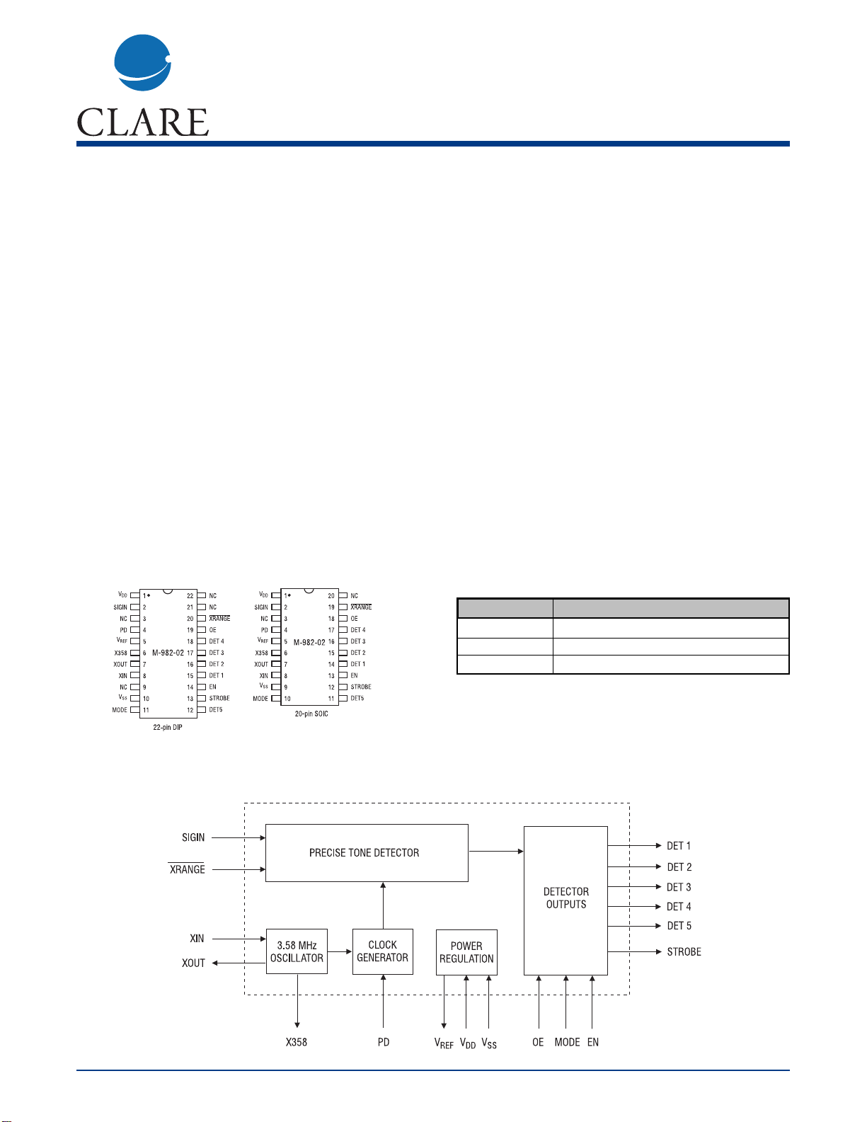
The M-982-02 is an integrated circuit precise tone
detector for special-purpose use in automatic following
of switched telephone calls. The circuit uses lowpower CMOS techniques to provide the complete filtering and control required for this function. The basic
timing of the M-982-02 is designed to permit operation
with almost any progress tone system.The use of integrated circuit techniques allows the M-982-02 to pack
the five filters for call progress following into a single
22-pin DIP or 20-pin SOIC. A 3.58 MHz crystal-controlled time base guarantees accuracy and repeatability.
The M-982-02 is an enhanced drop-in replacement for
the M-982-01. It has a wider operating voltage range
(down to 3V). It has lower power consumption under
normal operating conditions. In addition, a powerdown (PD) feature is provided to further reduce power
consumption when inactive. It includes a 425 Hz
detector to support common international call progress
requirement.
Block Diagram
Ordering Information
Part # Description
M-982-02P 22-pin plastic DIP
M-982-02S 20-pin plastic SOIC
M-982-02T 20-pin plastic SOIC,Tape and Reel
Pin Diagram
Page 2
www.clare.com
2
M-982-02
Rev. 4
Absolute Maximum Ratings
Storage Temperature -40 to 150°C
Operating Ambient Temperature -40 to 85°C
V
DD
7V
Input Voltage on SIGIN VSS- 6.5 to VDD+ 0.3V
Input Voltages (except SIGIN) VSS- 0.3 to VDD+ 0.3 V
Lead Soldering Temperature 260° C for 5 seconds
Note: Exceeding these ratings may permanently damage the M-982-02.
Absolute Maximum Ratings are stress ratings. Stresses in
excess of these ratings can cause permanent damage to
the device. Functional operation of the device at these or
any other conditions beyond those indicated in the operational sections of this data sheet is not implied. Exposure of
the device to the absolute maximum ratings for an extended period may degrade the device and effect its reliability.
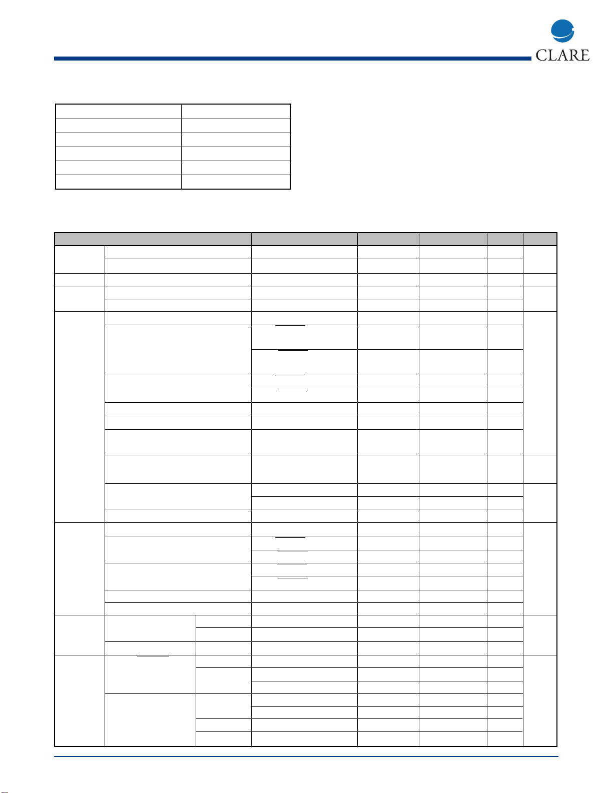
Specifications
Parameter Conditions Min Max Units Notes
Operating V
DD
- 2.7 5.5 V -
Conditions Power supply noise 0.1 - 5 kHz - 20 mV p-p
Power Current drain (I
DD
)V
REF
open - 15 mA -
V
REF
V
REF
- 48% of V
DD
52% of V
DD
V-
Impedance - 3.25 8.25 kW
Signal Frequency range in-band signal -1 +1 % of f
o
1
Detection Level: V
DD
= 5.0V XRANGE = open -30 0 dBm
(24.5 mV) (775 mV)
XRANGE = V
SS
-40 -10 dBm
(7.8 mV) (245 mV) -
Level: V
DD
= 3.0V XRANGE = open -33 (17.4 mV) -3 (549 mV) dBm
XRANGE = V
SS
-43 (5.5 mV) -13 (173.5 mV) dBm
Duration (t
DD
) - 200 - ms
Bridge time (t
BB
)--20ms
Level skew between adjacent
inband signals for detection of both - 6 dB
High level to low level signal for high = 0 dBm (775 mV) 1 - s detection of both (t
IL
) low = -30 dBm (24.5 mV)
Time to output (t
DO
) SIGIN ≈ -24 dBm - 200 ms
SIGIN < -24 dBm - 240 ms -
Time from DET n to STROBE (t
DS
)- -10ms
Signal Frequency range - -6 -6 % of f
o
1
Rejection Level: V
DD
= 5.0V XRANGE = open - -50(2.5 mV) dBm
XRANGE = V
SS
- -60 (0.8 mV) dBm
Level: V
DD
= 3.0V XRANGE= open - -53 (1.7 mV) dBm
XRANGE = V
SS
- -63 (.6 mV) dBm
Interval duration (t
ID
) - 160 - ms
Time to output (T
IO
) - - 200 ms
Outputs DET n, V
OL
I
SINK
= -1mA - 0.5 V
STROBE pins V
OH
I
SOURCE
=1mA VDD-0.5 - V -
DET n pins I
OZ
VO=VDD, V
SS
-1µA
Inputs EN, OE, XRANGE, VIL - - 0.5 V -
MODE, PD pins VIH VDD = 5V VDD - 2.0 - V
VDD = 2.7V VDD - 0.5 - V
Pull-up and Pull-down MODE = VSS VDD = 5V 12.5 50 µA
currents VDD = 2.7V 4 20 µA
/Xrange = VSS - 2 6 µA
PD =VDD - 4 10 µA
Page 3
M-982-02
www.clare.com
3
Rev. 4
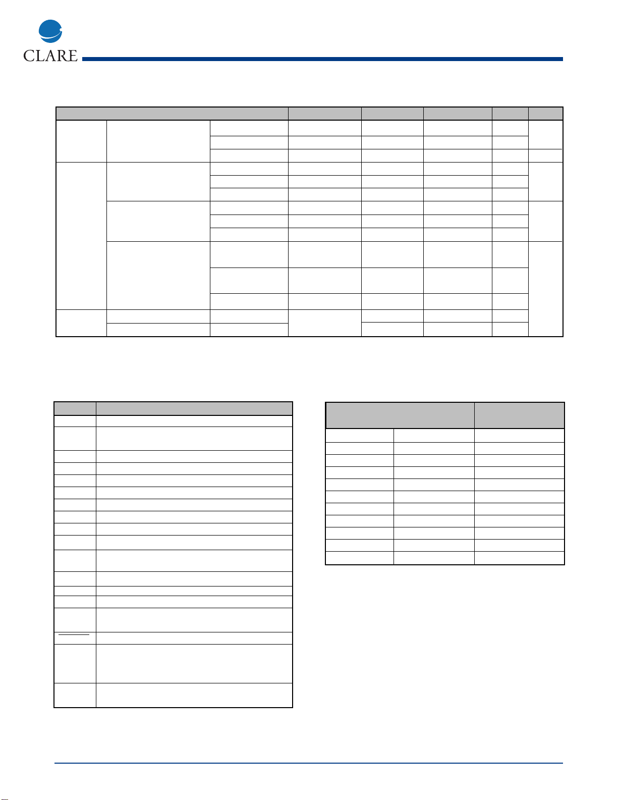
Call Progress Tones
Frequency (HZ) Use
12
350 440 Dial Tone
400 Off Special
440 Off Alert Tone
440 480 Audible Ring
440 620 Pre-empt
480 Off Bell High Tone
480 620 Reorder (Bell Low)
350 Off Special
620 Off Special
941 1209 DTMF “*”
425 Off European
Specifications (continued)
Parameter Conditions Min Max Units Notes
SIGIN pin Voltage range - -6.5 VDD V
Input impedance f=500 Hz 80 - kΩ
Input spectrum - - 28 kHz
Clock External clock VIL XOUT open - 0.2 V
connected to XIN pin VIH XOUT open VDD-0.2 - V
Duty cycle XOUT open 40 60 %
XIN, XOUT with crystal Capacitance - - 10 pF
osc. active Internal resistance - 20 - MW
Power up (TPU) PD hi to lo - 30 ms
X358 pin VOL CL = 20 pF, - 0.2 V
ISINK = -1mA
VOH CL = 20 pF,
ISOURCE =1mA VDD - 0.2 - V
Duty cycle CL = 20 pF 40 60 %
Tri-state tEN,(High Z to Low Z) CL = 50 pF, - 250 ns
Operation tDE,(Low Z to High )Z RL = 100 kW - 250 ns
Unless otherwise noted, VDD- VSS= 5V, Ta = 25°C, PD at logical low state, and XRANGE at a logical high state.
Power levels are in dBm referenced to 600 ohm. DC voltages are referenced to V
SS
.
Notes:
1. Per tone.
Pin Functions
Pin Funtion
DET 1 Active high tri-state output, detect for 350 Hz.
DET 2 Active high tir-state ooutput, detect for 400/620 Hz.
(See Note.)
DET 3 Active high tri-state output, detect for 440 Hz.
DET 4 Active high tri-state output, detect for 480 Hz.
DET 5 Active high tri-state output, detect for 425 Hz.
EN Active high enabled, when low drives STROBE low.
OE Active high input. When low tri-state DET n pins.
SIGIN Analog signal input (internally capacitive coupled).
STROBE Active high output, indicates valid DET n.
V
DD
Most positive power supply input pin.
V
REF
Internally generated mid-power supply voltage
(output).
V
SS
Most negative power supply input pin.
X358 Buffered oscillator output (3.58 MHz).
XIN Crystal oscillator or digital clock input.
XOUT Crystal oscillator output. Used only with a crystal.
Use X358 when clock output signal is required.
XRANGE Active low input. Adds 10 dB of gain to input stage.
MODE Compatibility selection. Connection to VSS selects
400 Hz detection. (M-981-02 emulation.) Connection
to VDDor no connection selects 620 Hz detection.
PD Power-down operation, logic high inhibits internal
clock. Internal pulldown resistor.
Note: This output indicates 400 Hz detect when MODE is connected to VSSand 620
Hz detect when open, or connected to VDD.
Page 4

Truth Table
Signal Present (fo) Mode Det 1 Det 2 Det 3 Det 4 Det 5 Strobe PD OE EN
350 Hz X 1 X X X X 1 0 1 1
400 Hz (Note) 0 X 1 X X X 1 0 1 1
620 Hz (Note) 1/open X 1 X X X 1 0 1 1
440 Hz X X X 1 X X 1 0 1 1
480 Hz X X X X 1 X 1 0 1 1
425 Hz X X X X X 1 1 0 1 1
Other (no detect) X 0 0 0 0 0 0 0 1 1
Any X 0 0 0 0 0 0 1 1 X
Any X 0 0 0 0 0 0 0 1 0
Any X High Impedance X 0 0 1
Any X High Impedance 0 0 0 0
Any X High Impedance X 1 0 X
www.clare.com
4
M-982-02
Rev. 4
Call Progress Tone Detection
Call progress tones are audible tones sent from
switching systems to calling parties to show the status
of calls. Calling parties can identify the success of a
call placed by what is heard after dialing. The type of
tone used and its timing vary from system to system,
and though intended for human ears these signals can
provide valuable information for automated calling systems.
The M-982-02 contains five signal detectors sensitive
to the frequencies often used for these progress tones.
Electronic equipment monitoring the DET n outputs of
the M-982-02 can determine the nature of signals
present by measuring their duty cycle. See the TriState Timing Diagram on page 5 for a diagram of a circuit that could be used to permit a microcomputer to
directly monitor tones on the telephone line. Much of
the character of the progress tones is in their duty
cycle or cadence (sometimes referred to as interruption rate). This information, coupled with level and frequency indication from the M-982-02, can be used to
decide what progress tones have been encountered.
For example,dial tones as shown in the Call Progress
Tone tabel on page 3 are usually “on” continuously and
last until the first dial digit is received by the switching
system. Line Busy, on the other hand, is turned off and
on at a rate of 1 Hz with a a 50% duty cycle, or an interruption rate of 60 times per minute (60 IPM). The tones
can be distinguished in this way. It should be noted that
while such techniques will usually be effective, there
are some circumstances in which the M-982-02 cannot
be accurately used. Examples include situations
where ringback tone may be short or not even encountered. Ringback may be provided at ringing voltage frequency (20 or 30 Hz) with some harmonics and may
not fall in the detect range, and speech or other strong
noise may obscure tones making cadence measurement difficult.
Standards do exist and should be consulted for your
particular application. In North America AT&Ts “Notes
on the Network” or EIAs RS-464 PBX standard should
be reviewed. In Europe tone plans may vary with
locale, in which case the CEPT administration in each
country must be consulted. Outside these areas,
national PTT organizations can provide information on
the systems within their borders.
Page 5

M-982-02
www.clare.com
5
Rev. 4
Signal Timing
Tri-State Timing
Power-Down Timing
Typical Application
Page 6

Tolerances (mm) SAE
approximation(inches)
Min Max Min Max
A 2.35 2.65 .0926 .1043
A1 .10 .30 .0040 .0118
b .33 .51 .013 .020
D 12.60 13.00 .4961 .5118
E 7.4 7.6 .2914 .2992
e 1.27 BSC .050 BSC
H 10.00 10.65 .394 .419
L .40 1.27 .016 .050
Tolerances (inches) Metric
Approximation (mm)
Min Nom Max Min Nom Max
A - - .210 - - 5.33
A1 .015 - - .38 - -
b .014 - .022 .36 - .56
b2 .045 .060 .065 1.1 1.5 1.7
C .009 - .015 .23 - .38
D 1.065 1.085 1.120 27.1 27.6 28.4
E .390 .415 .425 9.9 10.5 10.8
E1 .330 .360 .390 8.4 9.1 9.9
e .100 BSC 2.54 BSC
ec 0° 15° 15° 0° 15°
L .115 .130 .160 2.9 3.3 4.1
www.clare.com
6
M-982-02
Rev. 4
Package Dimensions
Dimensions
mm
(inches)
Page 7

Worldwide Sales Offices
CLARE LOCATIONS
Clare Headquarters
78 Cherry Hill Drive
Beverly, MA 01915
Tel: 1-978-524-6700
Fax: 1-978-524-4900
Toll Free: 1-800-27-CLARE
Clare Switch Division
4315 N. Earth City Expressway
Earth City, MO 63045
Tel: 1-314-770-1832
Fax: 1-314-770-1812
Clare Micronix Division
145 Columbia
Aliso Viejo, CA 92656-1490
Tel: 1-949-831-4622
Fax: 1-949-831-4628
SALES OFFICES
AMERICAS
Americas Headquarters
Clare
78 Cherry Hill Drive
Beverly, MA 01915
Tel: 1-978-524-6700
Fax: 1-978-524-4900
Toll Free: 1-800-27-CLARE
Eastern Region
Clare
603 Apache Court
Mahwah, NJ 07430
Tel: 1-201-236-0101
Fax: 1-201-236-8685
Toll Free: 1-800-27-CLARE
Central Region
Clare Canada Ltd.
3425 Harvester Road, Suite 202
Burlington, Ontario L7N 3N1
Tel: 1-905-333-9066
Fax: 1-905-333-1824
Western Region
Clare
1852 West 11th Street, #348
Tracy, CA 95376
Tel: 1-209-832-4367
Fax: 1-209-832-4732
Toll Free: 1-800-27-CLARE
Canada
Clare Canada Ltd.
3425 Harvester Road, Suite 202
Burlington, Ontario L7N 3N1
Tel: 1-905-333-9066
Fax: 1-905-333-1824
EUROPE
European Headquarters
CP Clare nv
Bampslaan 17
B-3500 Hasselt (Belgium)
Tel: 32-11-300868
Fax: 32-11-300890
France
Clare France Sales
Lead Rep
99 route de Versailles
91160 Champlan
France
Tel: 33 1 69 79 93 50
Fax: 33 1 69 79 93 59
Germany
Clare Germany Sales
ActiveComp Electronic GmbH
Mitterstrasse 12
85077 Manching
Germany
Tel: 49 8459 3214 10
Fax: 49 8459 3214 29
Italy
C.L.A.R.E.s.a.s.
Via C. Colombo 10/A
I-20066 Melzo (Milano)
Tel: 39-02-95737160
Fax: 39-02-95738829
Sweden
Clare Sales
Comptronic AB
Box 167
S-16329 Spånga
Tel: 46-862-10370
Fax: 46-862-10371
United Kingdom
Clare UK Sales
Marco Polo House
Cook Way
Bindon Road
Taunton
UK-Somerset TA2 6BG
Tel: 44-1-823 352541
Fax: 44-1-823 352797
ASIA/PACIFIC
Asian Headquarters
Clare
Room N1016, Chia-Hsin, Bldg II,
10F, No. 96, Sec. 2
Chung Shan North Road
Taipei, Taiwan R.O.C.
Tel: 886-2-2523-6368
Fax: 886-2-2523-6369
http://www.clare.com
Clare, Inc. makes no representations or warranties with respect to
the accuracy or completeness of the contents of this publication
and reserves the right to make changes to specifications and
product descriptions at any time without notice. Neither circuit
patent licenses nor indemnity are expressed or implied. Except as
set forth in Clare’s Standard Terms and Conditions of Sale, Clare,
Inc. assumes no liability whatsoever, and disclaims any express or
implied warranty, relating to its products including, but not limited to, the implied warranty of merchantability, fitness for a particular purpose, or infringement of any intellectual property right.
The products described in this document are not designed,
intended, authorized or warranted for use as components in systems intended for surgical implant into the body, or in other applications intended to support or sustain life, or where malfunction
of Clare’s product may result in direct physical harm, injury, or
death to a person or severe property or environmental damage.
Clare, Inc. reserves the right to discontinue or make changes to its
products at any time without notice.
Specification: DS-M982-02-R4
©Copyright 2001, Clare, Inc.
All rights reserved. Printed in USA.
7/24/01
 Loading...