

Page 1

#’
-SHARP
SPECIFICATIONS
Product Type : l’7%FG lens-integrated CMOS Color Area Sensor for CIF
Yodel No.
%This specifications contains 24 pages including the cover.
If you have any objections,please contact us before issuing purchasing order.
CUSTOMERS AcCEpTANCJ3
DATE :
BY:
LZOP3820
PRESENTED
I Dept. General Manager
REVIEWD BY:
PREPARED BY:
Product Development Dept. II
CCD Development Center
Integrated Circuits Devel
SBABP CORPORATION
Page 2

SHARP
l
Handle this document carefully for it contains material protected by international
copyright law. Any reproduction, full or in part, of this material is prohibited
without the express written permission of the company.
l
Vhen using the products covered herein, please observe the conditions written herein
and the precautions outlined in the following paragraphs. In no event shall the
company be liable for any damages resulting from failure to strictly adhere to these
conditions and precautions,
(1) The products covered herein are designed and manufactured for the following
application areas. Vhen using the products covered herein for the equipment
listed in Paragraph (2>, even for the following application areas, be sure
to observe the precautions given in Paragraph CU. Never use the products
for the equipment listed in Paragraph (3).
*Office electronics
OInstrumentation
#Machine tools
SAudiovisual equipment
*Home appliances
Xommunication equipment other than for trunk lines
and
LZOP3820
measuring equipment
(2) Those contemplating using the products covered herein for the following
equipment which demands high reliability, should first contact a sales
representative of the company and then accept responsibility for incorporating
into the design fail-safe operation, redundancy, and other appropriate
measures for ensuring reliability and safety of the equipment and the overall
system.
*Control and safety devices for airplanes, trains, automobiles, and other
transportation equipment
*Mainframe computers
*Traffic control systems
*Gas leak detectors and automatic cutoff devices
,Bescue and security equipment
*Other safety devices and safety equipment,etc.
(3) Do not use the products covered herein for the following equipment which
demands extremely high performance in terms of functionality, reliability, or
accuracy.
-Aerospace equipment
Xcfnmunications equipment for trunk lines
Control equipment for the nucJear power
BMedical equipment related to life support, etc.
(4) Please direct all queries and comments regarding the interpretation of the
above three Paragraphs
to
a sales representative of the company.
industry
0 Please direct all queries regarding the products covered herein to a sales
representative of the company.
Page 3

SHARP
LZOP3820
CONTENTS
1
1. GENERAL DESCRIPTION
2. ARRANGEMENT OF PIXELS AND COLOR FILTORS
3. BLOCK DIAGRAM
4. PIN CONFIGURATION
5. PIN DESCRIPTION
6. ELECTRIC CHARACTERISTICS~
7. IMAGING CiiABACTERISTICS
8. LENS SPECIFICATIONS
9. TIMING DIAGRAM
. 10. DESCRIPTION OF SERIAL DATA
1 1. EXAMPLE OF STANDARD OPERATING CIRCUIT
12. SPECIFICATION FOR BLEMISH
,..1,1,.111.1...,1...*.1...1.1,.,.,...**.*.
~,I,*o.I.,Ill.l,.II,,.II1II1*1.L,~I~
I.,,,I,..I...I..II.,.1O,IIOI..1,111..
ll,lI1111,1,1111,,,11,,11,1111,1.0,1~111
II.,,,.I,,.11.1..,,I.,,.L,,III,,
II.I......11,1,,I.,,,,.I..I..I,.I
..,.11...1.1,,1.1,,..1....,.1..1..1..
,,1,,,,1111.11111,,1,1~1,11~..~,..~~I1~..1
11111,1,,..1111.1111.011111,1
. . . . ..*..0..111,.1.10,11..1..
1**.111,*111.1,0
,.*..'.ll,,,*,l,ltl.
P. 2
P. 3
P. 4
P. 5
P. 6
P. 7
P. a
p. 9
P. IO
P. 13
P. 16
P. 17
1 3. CAUTIONS FOR USE
14. PACKAGE OUTLINE AND PACKING SPECIFICATI(JN
,1,,1.1,11..10,,,1....‘.,,~......,.~...
Illl,,l#ll.~l*t
P. 18
P. 20
Page 4
SHARF,
l.GENERAL DESCRIPTION
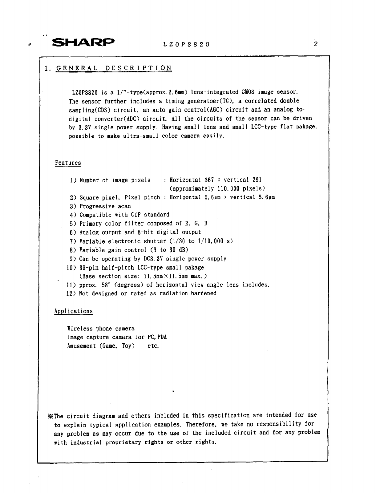
LZOP3820 is a l/7-type(approx.2.6mm) lens-integrated CMOS image sensor.
The sensor further includes a timing generatoer(TG), a correlated double
sampling(CDS) circuit, an auto gain control(AGC) circuit and an analog-to-
digital converter(ADC) circuit. All the circuits of the sensor can be driven
by 3.3V single power supply. Having smaI1 lens and small LCC-type flat pakage,
possible to make ultra-small color camera easily.
Features
1) Number of image pixels : Horizontal 367 x vertical 291
2) Square pixel, Pixel pitch : Horizontal 5.6Pm x vertical 5.6pm
3) Progressive acan
4) Compatible with CIF standard
5) Primary color filter composed of B. G, B
6) AnaIog output and a-bit digital output
7) Variable electronic shutter (l/30 to l/10,000 s>
8) Variable gain control (3 to 30 dB)
9) Can be operating by DC3.3V single power supply
10) 36-pin half-pitch LCC-type small pakage
(Base section size: ll.5mmXll. 5mm max. )
11) pprox. 58” (degrees) of horizontal view angle lens includes.
12) Not designed or rated as radiation hardened
LZOP3820 2
(approximately 110,000 pixels)
Applications
Yireless phone camera
Image capture camera for PC,PDA
Amusement (Game, Toy) etc.
.
#The circuit diagram and others included in this specification are intended for use
to explain typical application examples. Therefore,
any problem as may occur due to the use of the included circuit and for any problem
with industrial proprietary rights or other rights.
we take no responsibility for
Page 5
SHARP
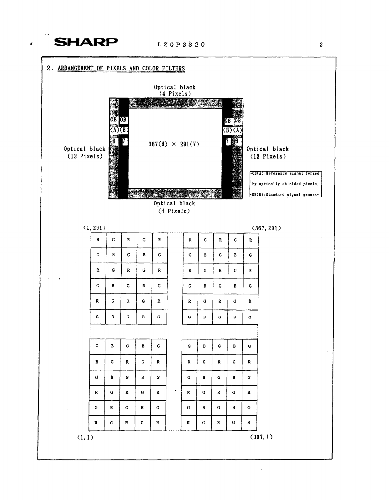
2. -T .OF PIXELS AND COLOR FILTERS
LZOP3820 3
Optical black
(4 Pixels)
Optical black
(13 Pixels)
(1
.
367(H) x 291(V)
Optical black
(4 Pixels)
, 1
R
. . ..-
Optical black
(13 Pixels)
by opticaliy shielded pixels
OB(B):Standard signs1 genera-
(367.291)
lG IRI
(367.1)
Page 6
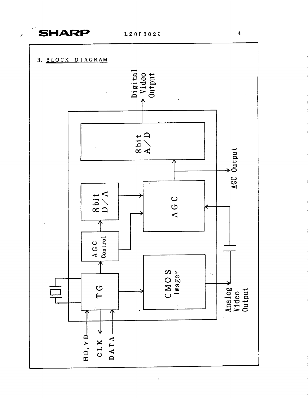
D/A
+ 8bit
Digital
output
-+ Video
8bit
A/D
V
>
AGC
AGC
I
+
HD,VD-
+ Control
TG
3
CLK t-
DATA-
I
V
.
output
Page 7

:*
-’ SHARP
4.PIN CONFIGRATION
LZOP3820
VIEW>
BIAS1
SCLK
CLP
OFS
BIAS2
SICOUT
SIGIN
ACND
AVDD
N. c.
LZOP3820
N. c.
D5
D4
D3
D2
Dl
DO
DGMD
DVDD
Page 8
*a
a
SHARP
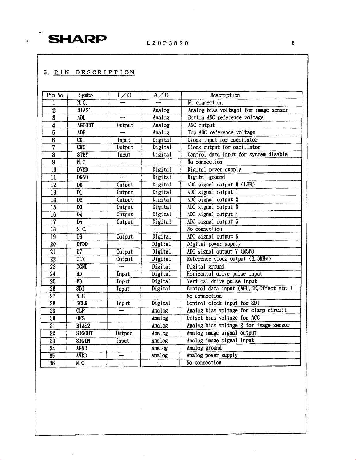
5. PIN DESCRIPTION
LZOP3820 6
STBY
N. C.
DVDD
DGND
ii
13 Dl
14 D2
15 D3
16 D4
17 D5
18 1
19 I D6
I
20
21 D7
sl.7 -7 ” n ‘ .I n1 -~:L-, l--d------- -1--1. -__A.-__A /n rxlR,-\
zg
23 1 DGND I - 1 Digital 1 Digital mound
27 1 N. c. - 28
29 CLP - Analog
DO
N.
C.
DVDD
1 LLh 1 uuqlur 1
HD
VD
I
I iDI
1 SCLK Input Digital 1 Control clock input for SD1
._
rs
BIAS2
I++--
33
34
t=k-
35
1 36 1
SIGOUT
SIGIN
AGND
AVDD
N. C.
Ir;
-
-
1 I
I OutDut I Digital 1 ADC signal output 0 (L SB)
outp,t Digital 1 AJX si&l output 1
output Digital ,
output
output Digital ,
Output Digital 1 AIX s&al output 5 I
- -
I outDut I
-
output Digital ADCsigna _
! I
1 Input
1 hlDUt I
I I I
I Input I
- Analog
Digital 1 Digital power supply
I Di
.gital 1 Digital ground I
1
ADC simal
Digital 1 AM: signal output 3 1
Digital I ADC signal output 6
Digital Digital power SUDDEN 1
mgisal I nererence
-- ~~
Digital Horizontal drive pulse input
Digital Vertical drive Dulse inmt
Diiital I Control data input (AGCiEE,Offset etc. > 1
I ADC siml output 4 I
1 No connection
I No connection
I -~-~~-~ --
Analog bias voltage for clamp circuit
Offset bias voltage for AGC
Analog bias voltage 2 for image sensor
Analog image signal output
-Analog image signal input
Analog ground
Analog power supply
No connection
OutDut 2 I
1 OUtDUt 7
CIWK ouepu~ \Y. urhuu/
(MSB)
I
J
Page 9

SHARP
6.ELECTRIC CHARACTERISTICS
6 - 1. ABSOLUTE MAXIMUM BATINGS
Parameter S)TllbOi Wings Unit
Power supply voltage VDD
Input signal voltage V@
Storage temperature Tstr
6 - 2. BECOBBNDED OPEBATING CONDITIONS
LZOP3820 7
-0.3 - 4.6
-0.3
-20
- VDD+O. 3 V
-70
V
@c
Parameter
Power supply voltage
Oneratine temnerature
or--- ---..a --c-m ~~~ .
Oscillator frequency
Digital input Low level
vo 1 tage High level
Analog input voltage
Analog bias voltage
Note 1
Note 2
Note
: Apply to input pins HD, VD, SD1 and SCLK
: Apply to input pin SIGIN, Please do not connect to DC directly.
3
: Apply to pins BIASI, BIASZ, OFS, ADL, DAL, CLP.
Please do not connect to GND directly.
SYUlbOl
YIN ‘lYP
VDD
Tonr
Fck 9-o MHZ
V9L
VdJH
3. 0 3.3
-10 25
__
0.8VDD VDD V
(Connect to terminal
through capacitor)
(Connect to GND
through capacitor)
MAX Unit Note
3. 6 V
60 "c
0.2VDD V
1
2
3
Page 10

C’
~5
SHARi=
LZOP3820
8
7. 7
Readout mode : l/30 see, Normal mode
Ambient temperature : 25 “C
Driving voltage : 3.3 V
Color temperature of light source : 3200K
*Measurement point : Analog image signal output (pin no.32) before ACC and AD.
I
[Note]'
(a> Vo is the average output voltage of Green channel int the central areaWlO,V/lO) under
uniform illumination. The standard exposure condition is defined when Vo is 150 mV.
(b) The image area is divided into IO x 10 segments under 10 times exposure of the standard
exposure condition, The segment’s voltage is the average output voltages of all pixels
whithin the segments. Vsat is the minimum segment’s voltage of all the segments voltage.
cc> Vdark is the difference between average output voltage of the effective area and that of
the OB area, under non-exposure condition.
Cd).
Image area is divided into 10 X 10 segments under non-exposure condition. DSNU is defined
by
(Vdmax - Vdmin), where Vdmax and Vdmin are the maximum and minimun values of all
the segments voltage, respectively.
-(e> R(G) is the average output voltage of Green channel at central areaWlO.V/lO) when a
1000 Iux light source on a 90% reflector is image.
(f) One mean horizontal line signal <bi> is obtained by adding all the horizontal line
signals <aij> verticalIy and dividing them by the line number, <xi> is the deviation of
the center pixel from the average of successive 5 pixels in <bi>. V-FPN is the maximum
absolute value of (xi>.
(g)The limited resolusion in the central area(H/lO,V/lO) whitch the image of TV resolusion
chart(ex. EIAJ test chart:type-A) can be distinguished on the B/I video monitor when
converted into composite video signal.
(h)The limited resolusion in the perpheral area(image height:Y=O.7) under the conditions
mentioned above.
tilDefined following formura at the brightness of standard output voltage. Cat C-channel]
0ko/Vce)X100C%l
(j)Difference of center between
monitor size.
(k) IVDD is the total current of analog and digital power supply in the dark and on the
standard load condition.
Vco:output voltage of edge of the image. (image height:Y=O. 8)
Vce:output voltage of center of the image.
image
and monitor, Ratio of horizontal underscaning
Page 11

SHARP
8. LENS SPECIFICATIONS
Kondi t ions1
(a> Effective Image Area : (Hj2.06 x (V)l. 63mm
(b) TV distortion is defined the formura, (A y /Y > x 1 0 0 [%I
at capturing rectangular pattern sized Horizontal by Vertcal as 4by 3.
“Y” is defined as the Vertical height of center of Horizontal line.
* y” is defined as the Vertical height of edge of Horizontal line.
LZOP3820
t
(c) The range isthe best points by adjustment by screwing the lens head.
(d) Toruques which are necessary for turning the lens.
(at shipping of products)
.
Page 12

.-
, I
366 364 362. 360 358
64 68 72 7’6 80 84 88 ioie2
CLK(l).
9 - 1. Ho;izontal Pulse Timing
I . .
. .
. .
: * > !
KxXXXxxxrxwxxxxwxxxKxxX
,)B ._......._._._............... 08 2 4 6 8 10
124 128 132 138 140 144 148 152 156 160 164 158 172 176 180 184 188 192 196 200
x x x x x K x x x x x x x x x K x x x x n-T
()B . . . . . . . . . . . . . _ ._... _ . . . . . . .._ 08
1 08 .-.-.-.-.--..................OB
L
di 2 4 8 12 I8 20 24 28 32 36 40 44 48 52 56 60
906 Qld . . .
7 s 3
%Ixxxxxm
104 108 112 116 120
HD
(DO-D7 >
11rror
HD
CLK
nor*a1
(DO-D7)
ADOUT
Mirror
*The rising edge of HD pulse must be between two rising edges of CLKtO> and
*The falling edge of HD pulse must be between two rising edges of CLK(90) and CLK(91).
Page 13

,. ’
SHARP
LZOP3820
11
Page 14

SHARP
LZOP3820
12
,
Page 15

SHARP
LZOP3820
13
10. DESCRIPTION
OF SERIAL DATA
(Fix to
Low level)
D31
D32
D33 SAD1 (MS31
D34
D35
D36
D37
D38
MIRH
MIRV
SAD0 (LSB)
MAX2 (MSB)
MAX 1
MAX0 (LSB)
L PMD
Shutter
(Exposure time is 1 to l/330 frame period)
H:Horizontal mirror inversion image, L:Normal image
H:Vertical mirror inversion image,
Phase select of AD clock
(Fix to Low level)
Fixed gain select
(3
A:Power save mode (AGC and AD off), L:All active
speed control
L:Normal image
to 10 dB)
Page 16

SHARI=
10-l. SETTING OF AUTUN CONTROL
*One LSB of the gain code represents appoximately 0.156dB.
*Nominal gain values at
typical
LZOP3820
codes are shown below.
14
1
10-2.
-One LSB of the offset code represents appoximately 0.002Y.
-Nominal offset values at typical codes are shown below.
20
SETTtNG OF oFFSET LEVEL
H(HI HI RI H]
Page 17

SHARP
-One LSB of shutter speed code represents lfi, where 1H is HD pulse period.
LZOP3820
15
10-4.
*One LSB of gain code represents 1dB.
,SETTING OF FIXED GAIN
Page 18

SHARF,
ll.EXAMPLE OF OPERATING CIRCU
LZOP3820
16
I
1
I
A
3
w
Page 19

,*
.’
SHARP LZOP3820 17
12.SPECIFI&A-JION FOR BLEMISH
1) Definition of blemish
*Size of blemish : d 3 lines square by vertical lines.
[For reference] l Size of stain : 2 4 lines square by vertical lines.
White blemish
{note)
l
B :Blemish level defined in fig. below.
l vout
l
Vstd
: Average
output voltage at
Green channel.
: 150 mV. The standard output voltage defined in the specification of
* 7. Imaging Characteristics ”
<To be J&rmdb
(Green channel : 150mV)
$@efer to note below
2) Measureing conditions
l
Operating temperature : Topr = 25°C
* Operating voltage
l
Measureing point
: VDD = 3.3V
: Analog image signal output(Pin
White blemish
Black blemish
(a) Exposed
(Yout
= 150mV at Green channel)
fig. Definition of blemish level
No.32)
before AGC and AD.
White blemish
(b) Non-exposed
Page 20

SHARP
13. LAUTIONS FOR USE&
1, Package breakage
LZOP3820
In order to prevent the package, the lens holder and lens from being’broken, follow the
instructions below:
1) This CMOS image sensor is a precise optical component and the packaege-base material
is ceramic. Therefore, please be careful about the following instructions.
l
Take care not to drop the device when mounting. handling, or transporting.
l
Avoid giving a shock to the package. Especially when Ieads are fixed to the
shocks or the circuit board, a small shock could break the package more
easily tban when the package isn’t fixed.
2) If any damage or breakage occur on the surface of the lens, its characteristics
could deteriorate.
Therefore.
l Do not hit the Lens.
-Do not give a shock large enough to cause distortion,
*Do not scrub or scratch surface of the lens.
---
Even a soft cloth or applicator, if dry, could cause dust to scratch the Lens.
18
2. Electrostatic Darnage
. As compared with general MOS-LSI, CMOS image sensor has lower ESD.
Therefore, take the following anti-static measures when handling the CHCS image sensor.
1) Always discharge static electricity by grounding the human body and the instrument
to be used. To ground the human body, provide resistance of about 1MQ between the
hman body and the ground to be on the safe side.
2) When directly handling the device with the fingers, hoId the lens holder and do not
touth the lead,
3 > To avoid generating static electricity,
a. do not scrub the body and lens surface with cloth etc.
b. do not attach any tape or labels.
4) Vhen storing or transporting the device, put it in a container of conductive
material.
Page 21

. .
SHARI==
LZOP3820
3. Dust and contamination
Dust or contamination on the surface of lens and the inside of the lens holder could
deteriorate the output characteristic or cause a scar. In order to mini&e dust or
contamination on the device, take the following precautions:
1 > Do not remove the lens from the body.
Especially when adjusting macro, be careful not to remove the lens by turning it
counterclockwise too much
2) Do not touch the surface of the lens with the fingers. If dust or contamination gets
on the surface of the lens, the following cleaning method is recommended:
l IInadle the built-in lens CMOS image sensor in a clean environment such as a
cleaned both.
.(The cleanliness level should be, if possible, if possible class 1000 at least. >
*Dust from static electricity should be blown off with an ionized air blower.
For anti-electrostatic measures, however, ground all the leads on the device
before blowing off the dust.
=The contamination on the surface of the lens should be wiped off with a clean
applicator soaked in isopropyl alcohol. Wipe slowly and gently in one direction
only.
--- Frequently replace the applicator and do not use the same applicator to
clean more than one device.
l
Make sure there is no dust or contamination on the lens and screw it on the
lens holder.
19
4. Other
1) Soldering measure and condition.
*Use ESD-measured soldering iron.
*Do not put too much force onto the lens and the lens holder while soldering.
l
Be careful not to let the soldering iron touch the lens holder.
--- Soldering can be quickly/neatly done by laying the soldering iron so it
lightly touches the border between the package and the circuit board
and sliding it in sideways.
2) There is no guarantee of the performance of the device which haa been removed or
resoldered after being soldered once under the conditions mentioned above.
3 > Avoid using or storing the CMOS image sensor at high temperature or high humidity
as it is a precise optical component. Do not give a mechanical shock to the CMOS
i wage sensor.
4) Do not expose the device to strong light, For the color device, long exposure to
strong light will fade the color of the color filters.
Page 22

SHARP
1 4. PACKAGE OUTLINE AND PACKING SPECIFICATION J
1. Package Outline Specification
Refer to attached drawing
2.
Markings
Marking contents
(1) Product name
(2>Companyname : SHARP
(3)Countryname : JAPAN
(41Datecode : 1
: LZOP3820
I Denotes the production week
LZOP3820
I----- Denotes the production ref.code.(l--2figures)
Denotes the production day of the week
1 2 314
SUN. MON.
(01, ozo3,
Denotes the production year.
(Lower two digits of the year. >
TUE. 1 WED. TIIU. 1 FRI. 1 SAT.
l l l l
,52,53)
51617
Positions of markings are shown in the package outline drawing
But,ntarkings shown in theat drawing are not provided any measurements of their charactuers
and their positions.
!. Packing Specification
3 - 1. Packing materials
Device tray 1 Conductive plastic 1 Device packing(Gays/case)
(SUdevices/tray)
Cover tray
Rubber band
Buffer
Cushion bag
Tape
Label
3 - 2. External appearance of packing
Refer to attached drawing
. Precaution
1) Before unpacking, confirm the imports of the chapter ‘l&CAUTIONS FOE USE” in this
device specifications.
2) Unpacking should be done on the stand treated with anti-ESD. At that time, the same
anti-ED treatment should be done to operater’s body, too.
1 Conductive plastic(2trays/case) Device packing
Device tray fixing
Cardboard
Conductive
Paper
Paper
.
Shock absorber of device tray
Device tray fixing
Sealing cushion bag and device case
Indicates part number,
auantitv and date of manufacture
NIE NUMBER (NOTE)
--_-__________-_-_
C-HS3820A
Page 23

-.
SHARF,
LZOP3820
N
8
: I
: /
:
Page 24

T
,
SHARP
S __
LZOP3820
f
H
;i
w
0
a
d
T
c)
i
-
B
0 ‘g -xoJddy
Page 25

SHARP
LZOP3820
(UNIT :
mm)
!
\\ ---
is?iz
t \i
t4mMAw
yxIL(-T-~-oOUTIIwr a,,E : : : ; : : : 1 : : : : :
WrEGRATKJ CmJfrs (lc) GROW
SHARP CORPORATION
tt +
FTMSH
\
---
8%
NAME
,3--F i:::;;; :::: ;:
. m
DRAWING No.
External
Appearance
of Packing
I *.;:::::
: :
.
II., 9.. ; : :
= L;C:-:H’L’3’8i @A’
* * *
-
\ I
,
* .
;
’
J
 Loading...