

Page 1
PRODUCT DATA SHEET
or
t
ow
n
e
e
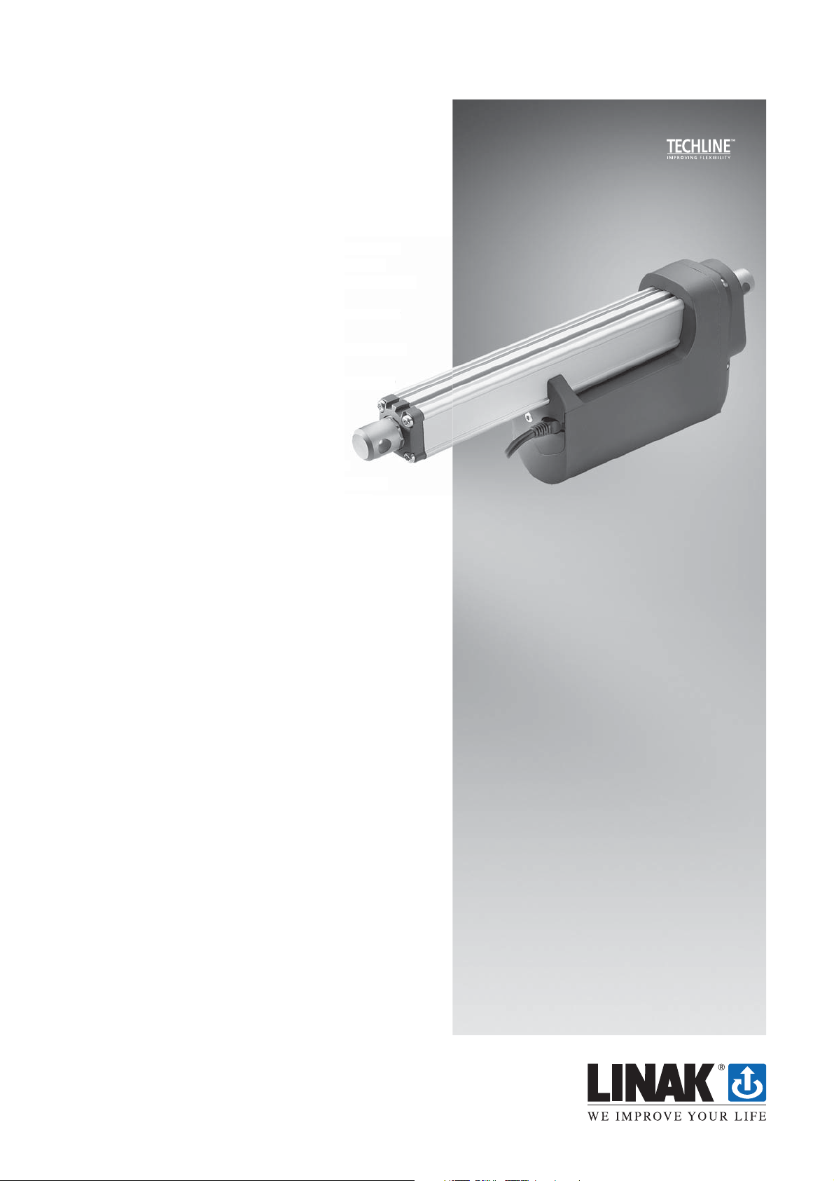
ACTUATOR
LA36
Features:
• 12, 24 or 36 V DC Permanent magnetic motor
with resetable thermal overload protection
• Thrust from 500 N - 10.000 N depending on gear
ratio and spindle pitch
• 10.000 N actuator cannot be ordered without
electrical endstop
• 10.000 N actuator can be ordered in push now
and pull from 01-09-207
• Max. speed up to 160 mm/sec. depending on
load and spindle pitch
• Heavy duty aluminium housing for
harsh conditions
• Highly efficient acme thread spindle
• Protection class: IP66 for outdoor use
(dynamic), furthermore the actuator can be
washed down by a high pressure cleaner
(IP69K - static)
• Hand crank for manual operation
• Mechanical overload protection through integrated
slip clutch (adjusted to 1.2 - 1.5 times max. load)
• Integrated brake, high self-lock ability
• End play – 2 mm max.
• Non rotating piston rod eye (turnable 0-90
degrees)
• Back fixture turnable in steps of 30 degrees
tic mot
tection
ing on gear
withou
push n
ding o
can b
Options:
• Built in end stop switches
• Adjustable magnetic sensors for end stop signals
(code no. 1017031)
• Hall effect sensor with A/B –signal
• Potentiometer full scale at 333 mm stroke with
8 mm pitch, 500 mm stroke with 12 mm pitch
and 833 mm with 20 mm pitch
• Different back fixtures and piston rod eyes
• Exchangeable cables in different lengths
Usage:
• Duty cycle at max. load 20% (up to 600 mm
stroke, for strokes between 601-999 mm the max.
duty cycle is 15%) at ambient temperature 25°C
• Ambient operating temperature -30°C to +65°C
full performance from 5 - 40°C
LA36 is ideal for use in harsh conditions. It is our
most solid actuator based on the philosophy
that it must be able to operate under extreme
conditions. The actuator is ideal for mobile “offhighway” equipment such as agricultural, forestry
and construction machines.
Page 2
Technical specifi cations
LA36 with 12V motor
Order number Push max.
362CXXXXXXXXXXX 10000 10000 13000 13000 8 11 7 100 - 999* 4.5 22
363AXXXXXXXXXXX 2600 2600 3400 3400 12 40.7 30.6 100 - 999 4.5 21
363BXXXXXXXXXXX 4500 4500 5800 5800 12 23.1 17.8 100 - 999* 4.5 20.7
363CXXXXXXXXXXX 6800 6800 8800 8800 12 15.5 11.9 100 - 999* 4.5 21
365AXXXXXXXXXXX 1700 1700 2200 2200 20 68 52 100 - 999 4.5 22
365FXXXXXXXXXXX 500** 500** 1000 1000 20 160 135 100 - 999 4.5 20
LA36 with 24V motor
Order number Push max.
362CXXXXXXXXXXX 10000 10000 13000 13000 8 11 7 100 - 999* Not tested
363AXXXXXXXXXXX 2600 2600 3400 3400 12 41 32.3 100 - 999 2.4 10.4
363BXXXXXXXXXXX 4500 4500 5800 5800 12 23.3 18.9 100 - 999* 2.4 10.2
363CXXXXXXXXXXX 6800 6800 8800 8800 12 15.7 12.7 100 - 999* 2.4 10.3
365AXXXXXXXXXXX 1700 1700 2200 2200 20 68 52 100 - 999 2.4 10.3
365FXXXXXXXXXXX 500** 500** 1000 1000 20 160 135 100 - 999 2.4 10.0
LA36 with 36V motor
Order number Push max.
362CXXXXXXXXXXX 10000 10000 13000 13000 8 11 7 100 - 999* Not tested
363AXXXXXXXXXXX 2600 2600 3400 3400 12 41 33.5 100 - 999 2.0 8.0
363BXXXXXXXXXXX 4500 4500 5800 5800 12 23.3 19.1 100 - 999* 2.0 8.0
363CXXXXXXXXXXX 6800 6800 8800 8800 12 15.7 12.8 100 - 999* 2.0 8.0
365AXXXXXXXXXXX 1700 1700 2200 2200 20 68 52 100 - 999 2.0 8.0
365FXXXXXXXXXXX 500** 500** 1000 1000 20 160 135 100 - 999 2.0 8.0
* There are limitations on the stroke length if you need full load, please see “ LA36 Load v. Stroke Length” on page 2.
** Note: Fully loaded actuators need a softstart in order to prevent the clutch slipping at start (see curves).
(N)
(N)
(N)
Pull max.
(N)
Pull max.
(N)
Pull max.
(N)
*Self-lock
min. (N)
Push
*Self-lock
min. (N)
Push
*Self-lock
min. (N)
Push
*Self-lock
min. (N)
Pull
*Self-lock
min. (N)
Pull
*Self-lock
min. (N)
Pull
Pitch
(mm/spindle rev.)
Pitch
(mm/spindle rev.)
Pitch
(mm/spindle rev.)
Typical speed
(mm/s)
Load
Standard stroke
lengths (mm)
In steps of 50 mm
Typical amp.
(A)
12 V
no full No load Full load
Typical speed
(mm/s)
Load
Standard stroke
lengths (mm)
In steps of 50 mm
Typical amp.
(A)
24 V
no full No load Full load
Typical speed
(mm/s)
Load
Standard stroke
lengths (mm)
In steps of 50 mm
Typical amp.
(A)
36 V
no full No load Full load
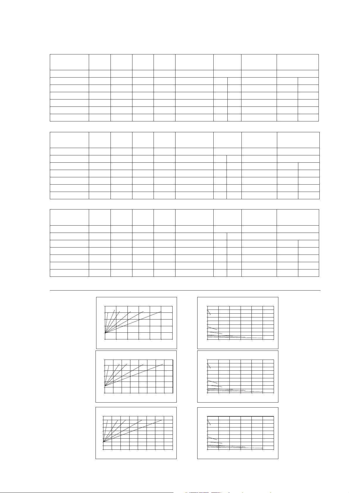
Speed and
current curves:
10.000N not tested
10.000N not tested
LA36 12V motor current v´s load
25
LA365A
LA363A
LA365F*
20
15
10
Ampere
5
0
0 2000 4000 6000 8000 10000 12000
LA36 24V motor current v´s load
12
10
8
6
Ampere
4
2
0
0 1000 2000 3000 4000 5000 6000 7000 8000
LA36 36V motor current v´s load
9
LA365F*
LA365A
8
7
6
5
4
Ampere
3
2
1
0
0 1000 2000 3000 4000 5000 6000 7000 8000
LA363C
LA363B
Load (N)
LA363A
Load (N)
LA363A LA363B LA363C
Load (N)
LA363B
LA362C
LA363CLA365ALA365F*
* Speed and current based on nominal power supply of 12, 24, 36VDC.
LA36 12V motor speed v´s load
180
160
140
LA365F*
120
100
80
LA365A
60
Speed (mm/s)
Speed (mm/s)
Speed (mm/s)
LA363A
40
20
0
0 2000 4000 6000 8000 10000 12000
180
160
140
120
100
80
60
40
20
0
0 2000 4000 6000 8000 10000 12000
180
160
140
120
100
80
60
40
20
0
0 2000 4000 6000 8000 10000 12000
LA363B
Load (N)
LA36 24V motor speed v´s load
LA365F*
LA365A
LA363A
LA363B
Load (N)
LA36 36V motor speed v´s load
LA365F*
LA365A
LA363A
LA363B
Load (N)
LA363C
LA363C
LA363C
LA362C
LA362C
LA362C
Page 3

LA36
Ordering example:
363A11+00xxxA20
Cable:
IP-degree:
0 = No cable
1 = 1.5 m power cable (0367002-1500)
2 = 5 m power cable (0367002-5000)
3 = 0.2 m power cable with AMP connector (0367006)
4 = 1.5 m power and 1.5 signal (0367002-1500+0367003-1500)
5 = 5 m power and 5 m signal (0367002-5000+0367003-5000)
6 = 1.5 m Y-cable, power and signal in one (0367020)
2 = Standard (IP66)
Motor type: A = 12 V DC with clutch
B = 24 V DC with clutch
C = 36 V DC with clutch
Stroke length: XXX = mm Acme spindle:
100, 150....999 mm
Feedback: 0 = Standard (No feedback)
H = Hall signal
P = Potentiometer (not possible with CS36)
End stop: 0 = No limit switches (not for spindle 2 and A)
1 = With limit switches
2 = With limit switches and end-stop signals
3 = CS36
4 = CS36 with end-stop signals
5 = With potential free limit switches
Safety nut: + = Without safety nut - Standard
S = With safety nut - only in push
Piston rod eye: 0 = M20 X 1 female adapter - 0361016
1 = ø 12.9 mm hole, for 1/2" pin - 0361018-B
2 = ø 12.2 mm hole, for 12 mm pin - 0361109-B
3 = M12 X 1.75 male adapter - 0361224
4 = M16 X 1.5 male adapter - 0361135
5 = ø 12.2 hole with slot (like LA34) - 0361138
Back fixture: 0 = M20 X 1 female adapter - 0361128
1 = ø 12.9 mm hole, for 1/2" pin - 0361129
2 = ø 12.9 mm hole turned 90°, for 1/2" pin - 0361129
3 = ø 12.2 mm hole, for 12 mm pin - 0361119
4 = ø 12.2 mm hole turned 90°, for 12 mm pin - 0361119
5 = M12 X 1.75 male adapter - 0361126
6 = M16 X 1.5 male adapter - 0361247
7 = ø 12.2 hole with slot (like LA34) - 0361140
8 = ø 12.2 hole with slot (like LA34) turned 90° - 0361140
Gearbox:
Spindle type:
8 mm pitch 12 mm pitch 20 mm pitch
A = Gear ratio 1 : 18 N.A. 2.600 N 1.700 N
B = Gear ratio 1 : 31 N.A. 4.500 N N.A.
C = Gear ratio 1 : 46 10.000 N 6.800 N N.A.
F = Gear ratio 1 : 7 N.A. N.A. 500 N
2 = 2-threaded acme spindle (8mm pitch)
3 = 3-threaded acme spindle (12 mm pitch)
5 = 5-threaded acme spindle (20 mm pitch)
A = 2 + adjustable reed limit switches (on outer tube)
C = 3 + adjustable reed limit switches (on outer tube)
E = 5 + adjustable reed limit switches (on outer tube)
Actuator type: 36 = LA36
Page 4

LA36 dimensions:
02= Turned 90˚
LA36 with adapter:
When STROKE >300 = Installation dimension: 250 + STROKE LENGTH
01= Standard
Adapter part number: 0361016 and 0361128
LA36 Load versus Stroke Length
10000
(8 mm)
6800
(12mm)
4500
(12 mm)
2600
(12 mm)
1700
(20 mm)
Load - Push & Pull(N)
500
(20 mm)
0 200 400 600 800 1000
N.B. LA36 500 - 1700 N is with 20 mm spindle pitch
LA36 2600 - 6800 N is with 12 mm spindle pitch
LA36 500 - 10.000 N is with 8 mm spindle pitch
When STROKE <=300 = Installation dimension: 188 + STROKE LENGTH
When STROKE >300 = Installation dimension: 238 + STROKE LENGTH
StrokeLength (mm)
Page 5

Connections diagram:
For 36xxxx+0H/Pxxxxxx and 36xxxx+1H/Pxxxxxx
Hall A
Hall B
Connections diagram:
For 36xxxx+30xxxB20, 36xxxx+3HxxxB20 and 36xxxx+40xxxB20
Connections diagram:
For 36xxxx+2Hxxxxxx
Connections diagram:
For 36xxxxx50xxxxxx
Connections diagram:
For 36xxxx+ 2Pxxxxxx and 36xxxx+20xxxxxx
Hall A
Hall B
End OUT
End IN
Note: If you wish to use the endstop signals, you will have to keep power on the brown and blue wires, otherwise the signal
will be lost.
Page 6

I/O specifications: Power supply - Motor
Item Specification Comment
Power supply
Input voltage 12 VDC, ± 20%
24 VDC, ± 10%
36 VDC, ± 10%
Duty cycle 20% at max. load Ambient temperature 25˚C
Input current
Connection To extend actuator:
2 - 21 Amp. depending on load and voltage (see graphs)
Connect Brown to positive
Connect Blue to negative
To retract actuator:
Connect Brown to negative
Connect Blue to positive
Note: Please note on varients with fast gear (500N-LA365F), it is necessary to use soft start to avoid the actuator clutch slipping when started.
Positioning feedback – Potentiometer.
Item Specification Comment
Absolute positioning
Potentiometer Bourns 0 - 10 K ohm A 5%, 10-Turn Type: 3540 Wirewound
Output range with
8 mm spindle pitch
Output range with 12 mm
spindle pitch
Output range with 20 mm
spindle pitch
Linearity ± 0.25%
Output protection 1 Kohm protection resistor
Connection Common - = Black
Note: Please note that Potentiometer is not possible on varients with fast gear (LA365F) -500N.
0 K ohm = 0 mm stroke
10 K ohm = 333 mm stroke
0 K ohm = 0 mm stroke
10 K ohm = 500 mm stroke
0 K ohm = 0 mm stroke
10 K ohm = 833 mm stroke
+10V exitation = White
0 = 10V out = Violet
Cable dimension: 2 x 2.5mm²
(2 x AWG14) for all different voltages.
Actuator direction can be controlled with a doublethrow switch with the middle position “off”
The same for all LA36 8 mm models.
e.g. 166.6 mm stroke = 5 Kohm
The same for all LA36 12 mm models
e.g. 250 mm stroke = 5 Kohm
The same for all LA36 20 mm models
e.g. 416.5 mm stroke = 5 Kohm
+10V or other value
Positioning feedback – Hall sensors.
Item Specification Comment
Relative positioning
Signal description Can be used for both direction and positioning
Input Voltage 12 - 36 V DC Cable dimension: 6 x 0.5 mm² (6 x AWG20) for all different voltages
Output voltage Always the same as input voltage
Resolution
(Distance the piston
rod moves per count)
Frequency Frequency is 14 - 26 Hz on A signal (and the same on B signal)
Current consumption 15 mA Also when actuator is not running
Switching capacity 40 mA, max. pr. channel Max. 680 nF
Connection Supply = Red
Diagram:
Note: max. output voltage 24 V DC
10000 N: Actuator = 0.124138 mm per count
6800 N: Actuator = 0.165517mm per count
4500 N: Actuator = 0.253846 mm per count
2600 N: Actuator = 0.432558 mm per count
1700 N: Actuator = 0.72093 mm per count
Movement per single Hall pulse:
10000 N Actuator = 0.496551 mm per pulse
6800 N Actuator = 0.662068 mm per pulse
4500 N Actuator = 1.015384 mm per pulse
2600 N Actuator = 1.730232 mm per pulse
1700 N Actuator = 2.88372 mm per pulse
depending on load
Hall A = Yellow
Hall B = Green
Common - = Black
Quadrature
Hall A
Hall B
Count
The Hall sensor signals are generated by the turning of the actuator
gearing
These signals can be fed into a PLC (Programmable Logic Controller).
In the PLC the quadrature signals (fig. 1) can be used to register the
direction and position of the piston rod
Low frequency with a high load
Higher frequency with no load
Input
to
PLC
Represents direction
and position.
Fig. 1
Page 7

LA36 Piston Rod Eye and Back Fixture options
Piston rod eye option
“0” Drawing no.: 0361016
Piston rod eye option
“2” Drawing no.: 0361109-B
Back fixture option
“0” Drawing no.: 0361128
Back fixture option
“3 & 4” Drawing no.: 0361119
Piston rod eye option
“1” Drawing no.: 0361018-B
Piston rod eye option
“3” Drawing no.: 0361224
Back fixture option
“1 & 2” Drawing no.: 0361129
Back fixture option
“5” Drawing no.: 0361126
Piston rod eye option
“4” Drawing no.: 0361135
Back Fixture orientation.
Back fixture option
“6” Drawing no.: 0361247
Piston rod eye option
“5” Drawing no.: 0361138
Back fixture option
“7 & 8” Drawing no.: 0361140
Standard “0” Degrees
“30” Degrees
“60” Degrees
“90” Degrees
“120” Degrees
“150” Degrees
Page 8

Available Circuits (LINAK code 1017031):
415A3
Connection Code V
Cable code 108
Circuit style B
Contact N.O.
Connection PNP
Indication LED
Voltage V DC 5...30
Voltage V AC 5...30
Max voltage drop V 0.1
Max power W 10
Max current mA 50
Varistor V -
Cable size mm
2
3 x 0,14
Sheath PVC
Circuit styles:
Manual hand crank
The manual hand crank can be used in the case of power failure.
The cover over the Allen Key socket must be unscrewed before the Allen Key can
be inserted and the Hand Crank operated.
Hand Crank Torque: Max.16 Nm (at maximum load)
Piston Rod movement per turn
Note:
• The power supply has to be disconnected during manual operation.
• If the actuator is operated as a Hand crank, it must be operated by hand or carefully by machine, otherwise there
is a potential risk of overloading and hereby damage actuator.
Gear A = 10.5 mm
Gear B = 6.0 mm
Gear C = 4.0 mm
Gear F = 27 mm
6 mm Allen key
The LA36 is tested according to the following standards:
Test Specification: Comment
Cold test EN60068-2-1 (Ab)
Dry heat EN60068-2-2 (Bb)
Change of temperature EN60068-2-14 (Na) Rapid change in temperature: +100°C to -30°C
Damp heat EN60068-2-30 (Db)
Salt spray EN60068-2-52 (Kb) Salt spray test: 500 hours incl. spraying periods + humidity storage
Degrees of protection EN60529-IP66 IP6X – Dust: Dust-tight
Chemicals BS7691/96 hours Resistant against: diesel, hydraulic oil, ethylene glycol, urea nitrogen, liquid lime, NPK fertilizers
Free fall Free fall from all sides: 0.4 meters on to steel
Vibration EN60068-2-36 (Fdb)
Bump EN60068-2-29 (Eb) Bump test: Level 40 g for 6 milliseconds. 3,000 bumps
Shock EN60068-2-27 (Ea) Shock test: Level 100 g for 6 milliseconds
Power supply ASAE EP455 (1990) Operating voltages: +10 V - + 16V
HF-immunity EN61000-6-2 Level: 30V/m. at 26 MHz – 1000 MHz; 80% 1 KHz
Emission EN61000-6-4 All levels are well within the norms of the emission standards
Insulation test Level: 500 V AC/25-100 Hz for 1 minute
Automotive transients ISO 7637 Load dump test only accepted on motor power connection
It is the responsibility of the product user to determine the suitability
of LINAK A/S products for a specific application. LINAK will at point of
delivery replace/repair defective products covered by the warranty
if promptly returned to the factory. No liability is assumed beyond
such replacement/repair.
EN60068-2-1 (Ad)
EN60068-2-2 (Bd)
EN60068-2-3 (Ca)
EN60068-2-6 (Fc)
Storage at low temperature: -40°C
Operating at low temperature: -30°C
Storage at high temperature: +90°C
Operating at high temperature: +60°C
Damp heat, Cyclic: Relative humidity 93 - 98 %
High +55°C, low +25°C
Damp heat, Steady: Relative humidity 93 - 95 %
+40°C ± 2°C
IPX6 – Water: No ingress of water causing damage
Random vibration: Short time 6.29 g RMS (Rod Mean Square)
Long time 7.21 g RMS
Sinus vibration: Freq. 5 - 25 Hz, amplitude = 3.3 mm pp
Freq. 25 - 200 Hz, acceleration 4 g
Over voltage +26(V) / 5 min
Specifications subject to change without prior notice.
Copyright © LINAK 2008.07 MA M9-02-148-F . Chapter 5.12
 Loading...