

Page 1

Ordering number: ENN7091
SANYO Electric Co.,Ltd. Semiconductor Company
TOKYO OFFICE Tokyo Bldg., 1-10, 1 Chome, Ueno, Taito-ku, TOKYO, 110-8534 JAPAN
Monolithic Linear IC
LA4266
3 W Monaural Power Amplifier
Overview
The LA4266 is a 3W power amplifier intended for televisions.
This IC has a series of pin compatible monaural and 2channel power amplifiers, thus allows the end product to
use a common circuit boad.
Features
• Television audio output.
• Pin compatible with the LA4267 (5 W)/4268 (10 W) and
the LA4276 (3 W × 2)/4277 (5 W × 2)/4278(10 W× 2).
• Package: SIP-10HD (2.54 mm pitch, straight pins).
• Thermal protection circuit and overvoltage protection
circuit on chip.
• Output power: 3 W (VCC = 16 V/RL = 8 Ω).
Specifications
Maximum Ratings at Ta = 25°C
Package Dimensions
unit: mm
3248-SIP10HD
[LA4266]
15.4max
(11.8)
4.5
2.4
0.4
1.2
25.6
C0.7
110
1.37
2.54
3.4
0.5
(10.0)
1.15
2.0
13.9
11.2
1.0 min
SANYO: SIP10HD
Parameter Symbol Conditions Ratings Unit
Maximum supply voltage V
Maximum output current IO peak 1.5 A
Allowable power dissipation Pd max Infinite heat sink 15.0 W
Thermal resistance
Operating temperature Topr –20 to +75 °C
Storage temperature Tstg –40 to +150 °C
CC
θ
j-c 3.0 °C/W
Rg = 0 25 V
Operating Conditions at Ta = 25°C
Parameter Symbol Conditions Ratings Unit
Recommended supply voltage V
Load resistance R
Operating supply voltage range VCC op Range does not exceed Pd 10 to 24 V
Any and all SANYO products described or contained herein do not have specifications that can handle
applications that require extremely high levels of reliability, such as life-support systems, aircraft’s
control systems, or other applications whose failure can be reasonably expected to result in serious
physical and/or material damage. Consult with your SANYO representative nearest you before using
any SANYO products described or contained herein in such applications.
SANYO assumes no responsibility for equipment failures that result from using products at values that
exceed, even momentarily, rated values (such as maximum ratings, operating condition ranges, or other
parameters) listed in products specifications of any and all SANYO products described or contained
herein.
CC
L
16 V
8 Ω
32902RM (II) No. 7091-1/6
Page 2

LA4266
Operating Characteristics at Ta = 25°C, VCC = 16 V, RL = 8 Ω, f = 1 kHz, Rg = 600 Ω, with specified board, in
specified circuit
Parameter Symbol Conditions
Quiescent current I
CCO
Rg = 0 25 50 mA
Voltage gain VG VO = 0 dBm 38 40 42 dB
Total harmonic distortion THD PO = 0.5 W 0.1 0.8 %
Output noise voltage V
Output power P
NO
O
Rg = 10 kΩ, BPF = 20 Hz to 20 kHz 0.25 1.0 mV
THD = 10 % 2.5 3.0 W
Ripple rejection SVRR Rg = 0, fr = 100 Hz, Vr = 0.5 Vrms 45 55 dB
Ratings
min typ max
Unit
Pd max – Ta
200 40 60 80 100 120 140
Allowable power dissipation, Pd max – W
16
15
14
12
10
Infinite heat sink
100 × 100 × 1.5 mm
11.7
8
50 × 50 × 1.5 mm
5.8
6
4
No heat sink
2
2
0
--20
Ambient temperature, Ta – °C
Pin Assignment and Equivalent Circuit Diagram
15
3
7.02
3
3.48
1.2
AI heat sink
Mounting
torque 39N•cm
Flat washer
Silicone grease
applied
ILA00835
160
30 kΩ
C1
100 µF
Filter
PRE GND
+
R1
NC
1 2 3 4
NC
C5
R2
V
CC
0.1 µF
1.0 Ω
IN
5 6 7 8910
750 Ω
+
C2
NF
300 Ω
+
C3
100 µF
R
4.7 µF
L
OUT
+
Power GND
C4
1000 µF
NC
+
C6
1000 µF
* For Muting, add a resistor between pin 3 and GND. 750 Ω for the LA4266/67/68, 200 Ω for the LA4276/77.
No. 7091-2/6
Page 3
LA4266
Description of External Parts
C1: Ripple filter capacitor
Decreasing the capacitance value reduces ripple rejection. This capacitor also affects the starting time; decreasing
the capacitance value makes the starting time earlier.
C2: Input capacitor
Because the DC potential of the input pin is not zero, this capacitor can not be omitted. Decreasing the capacitance
value to an extremely low level lowers the low frequency response.
C3: Feedback capacitor
Decreasing the capacitance value lowers the low frequency response. Increasing the capacitance value makes the
starting time later.
C4: Output capacitor
Decreasing the capacitance value causes insufficient power at low frequencies.
C5: Oscillation blocking capacitor
Decreasing the capacitance value causes oscillation to occur easily. Use a polyester film capacitor that has good high
frequency response and temperature characteristics.
The use of an electrolytic capacitor or a ceramic capacitor may cause oscillation to occur at low temperatures.
C6: Power capacitor
Decreasing the capacitance value causes ripple to occur easily. Locating at a distance from the IC or removing this
capacitor may cause oscillation to occur.
R1: Mute resistor
Refer to supplementary discussion “External Muting.’’
R2: Resistor connected in series with oscillation blocking capacitor
Prevents phase shift in conjunction with the oscillation blocking capacitor so that oscillation does not easily occur.
There is an optimal value for the resistor; increasing or decreasing the resistance causes oscillation to occur easily.
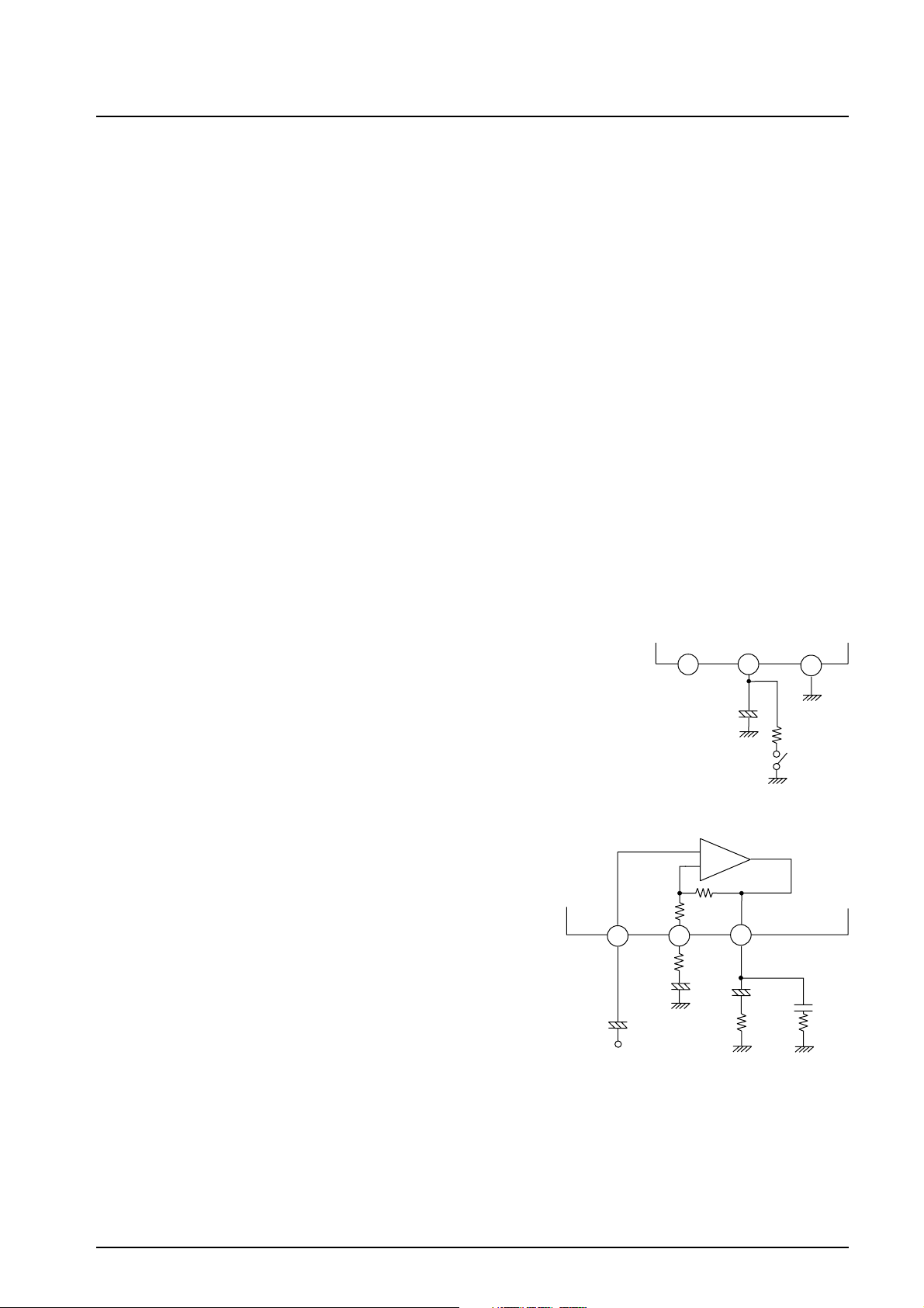
External Muting
• Pull down the electric potential of the ripple filter pin (pin 3).
Muting becomes possible by inserting the discharge resistor R1 between pin 3 and
GND. If the resistance value of R1 is too low, a popping noise is generated; if the
resistance value is too high, the muting effect is reduced. (A value of 750 Ω is
recommended for R1.)
Voltage Gain
The voltage gain is fixed at 40dB by the ratio of the 30 kΩ and 300 Ω
internal resistors. Therefore, it is not possible to use this IC with a
voltage gain greater than 40 dB. Although it is possible to use this IC
with a voltage gain of less than 40 dB by adding a feedback resistor
(RNF) and external resistors (R) as shown in the diagram, doing so
causes oscillation to occur easily. Therefore, do not use this IC with a
voltage gain of 30dB or less.
RNF
IN
5 6 7
C2
300 Ω
NF
R
C3
+
NC Filter
2 3 4
C1
30 kΩ
Rf
OUT
+
C4
R
L
PRE GND
+
R1
+
Mute SW
C5
R2
No. 7091-3/6
Page 4

LA4266
Notes on Using the IC
• Maximum ratings
When this IC is used near its maximum ratings, it is possible that a slight fluctuation in the operating conditions could
cause the maximum ratings to be exceeded, damaging the IC. Therefore, allow for an adequate safety margin in
regards to supply voltage, etc., so that the IC is never used under conditions that exceed its maximum ratings.
• Short circuit between pins
Applying power to the IC while a short circuit exists between two pins can cause damage or deterioration in the IC.
Therefore, after mounting the IC on a board, make sure that there are no solder bridges, etc., causing a short circuit
between any of the pins before applying power to the IC.
• Using the IC in a radio
When using this IC in a radio, make sure that there is enough distance between the IC and the bar antenna.
• Printed circuit pattern
When designing the printed circuit pattern, keep power, output, and ground lines thick and short, and determine the
placement of the pattern and the components in such a way as to prevent the generation of an I/O feedback loop.
In addition, power supply capacitor C6 and oscillation blocking capacitor C5 should be placed as close as possible to
the IC pins in order to prevent oscillation.
No. 7091-4/6
Page 5
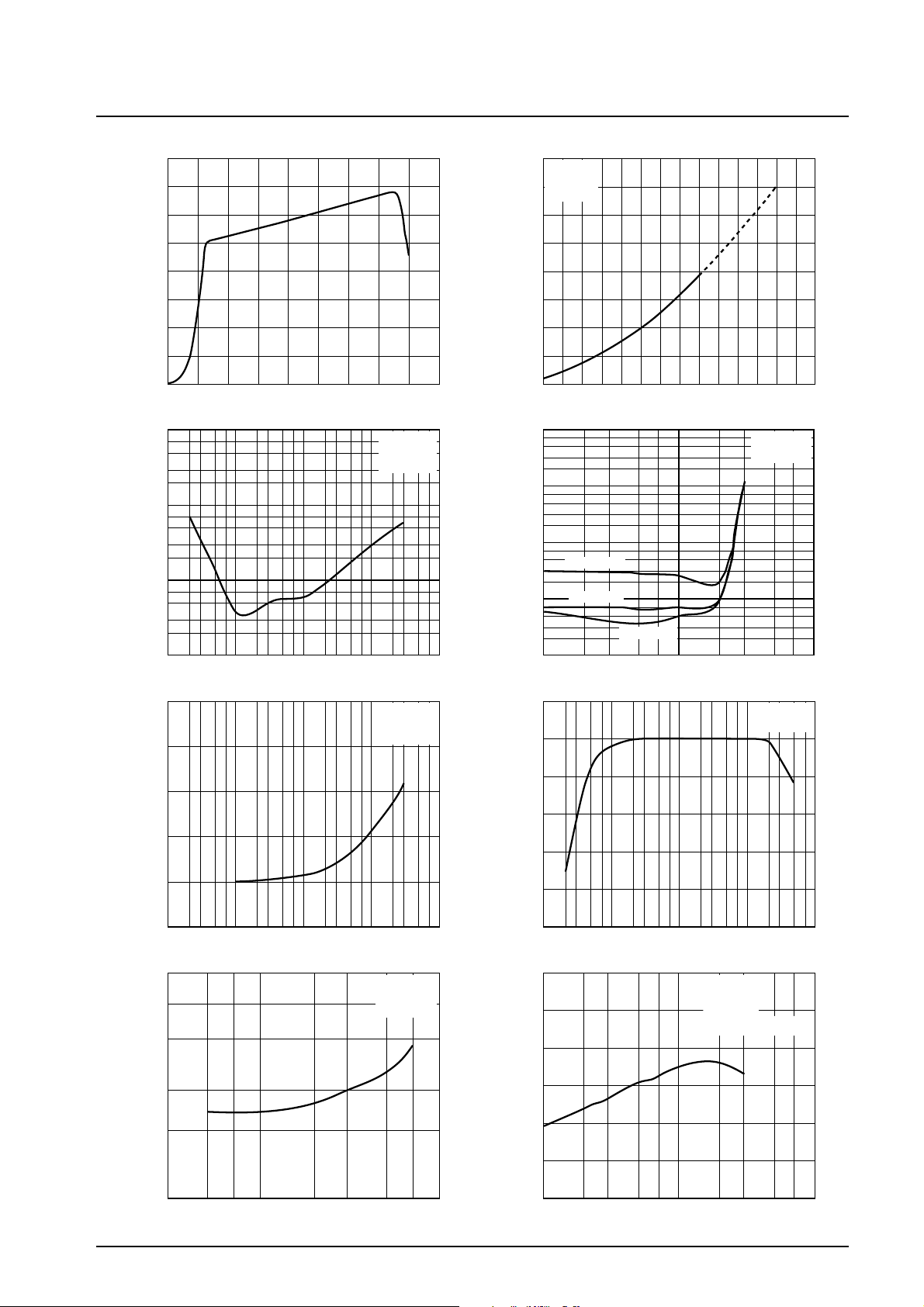
— mA
CCO
LA4266
I
– V
40
35
30
CCO
CC
16
RL = 8 Ω
f = 1 kHz
14
THD = 10%
12
— W
25
20
O
10
8
P
–
V
O
CC
15
10
Quiescent current, I
5
Total harmonic distortion, THD — %
0.01
0
0
10
7
5
3
2
1.0
7
5
3
2
0.1
7
5
3
2
10
0.5
0.4
105 152025303540
23 57 23 57 23 57 23 57
Supply voltage, V
THD – f
100
Frequency, f — Hz
VNO – Rg
— V
CC
1 k 10 k
ILA00836
RL = 8 Ω
PO = 0.5 W
V
= 16 V
CC
ILA00838
RL = 8 Ω
DIN Audio
V
= 16 V
CC
45
100 k
Output Power, P
Total harmonic distortion, THD -- %
100
0.01
6
4
2
0
12 16 20 24 28 32
8
7
5
3
2
10
7
5
3
2
1.0
7
5
3
2
0.1
7
5
3
2
0.1
1
0
Supply voltage, V
THD – P
O
CC
— V
V
CC
RL = 8 Ω
f = 10 kHz
f = 1 kHz
f = 100 Hz
23 57 23 57
Output power, PO — W
1.0
Response – f
RL = 8 Ω
V
CC
ILA00837
= 16 V
ILA00839
= 16 V
36
10
0.3
0.2
0.1
Output noise voltage, VNO — mVrms
0
23 57 23 57 23 57 23 57
10
1.0
7
5
3
2
100
Input signal source resistance, Rg — Ω
1 k 10 k
Vro – Vr
Output ripple voltage, Vro — mVrms
0.1
357 2357
0.1
Ripple voltage, Vr — V
ILA00840
Rg = 0
fr = 100 Hz
V
= 16 V
CC
ILA00842
100 k
1.0
Response — dB
Power dissipation, Pd — W
--1
--2
--3
--4
--5
23 57 23 57 23 57 23 57
10
3.0
2.5
2.0
1.5
1.0
0.5
0
0.1
100
1 k 10 k
Frequency, f — Hz
Pd – P
O
V
= 16 V
CC
RL = 8 Ω
f = 1 kHz
Pd = V
57 2 323 57
1.0
Output power, PO — W
CC
x I
ILA00841
CC
ILA00843
— P
100 k
O
10
No. 7091-5/6
Page 6
LA4266
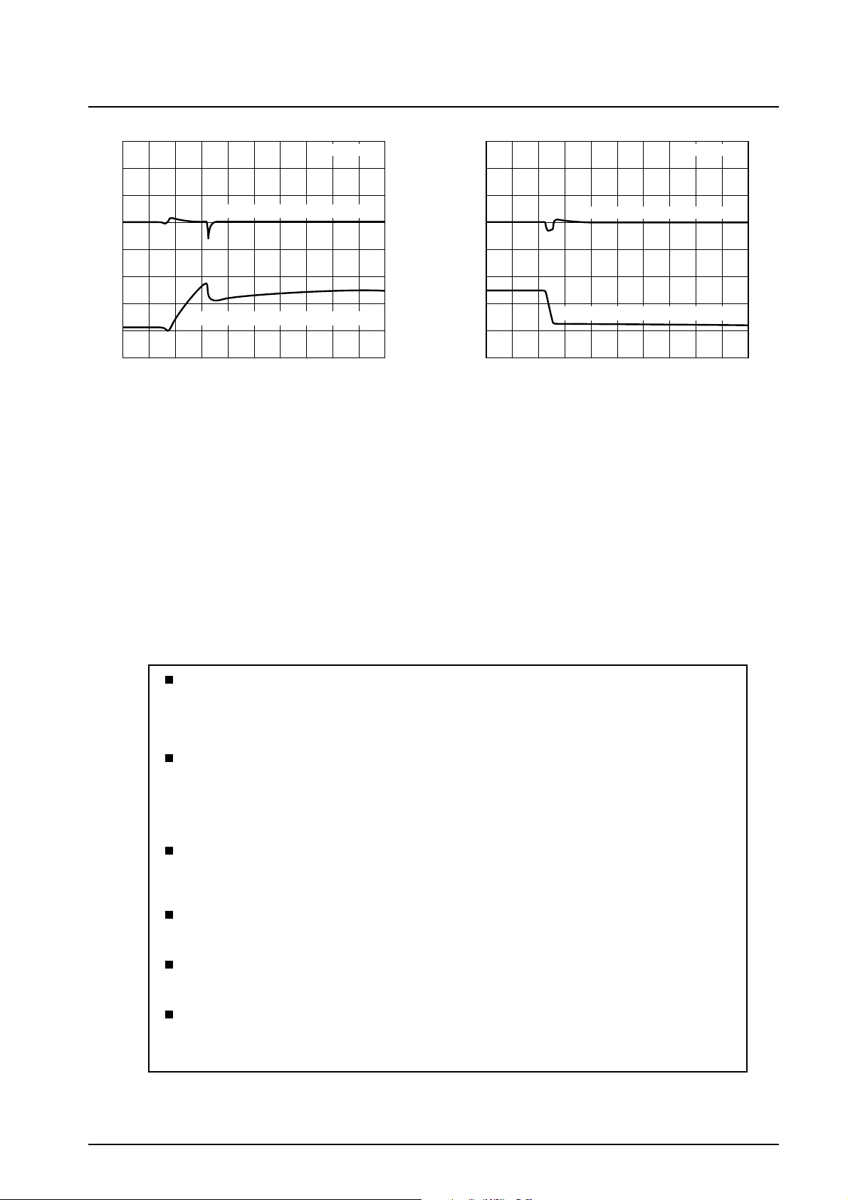
0.5 s/DIV
Pop noise waveform (1 V/DIV)
0
SP terminal AC
0
Pop noise waveform (1 V/DIV)
0.5 s/DIV
Output DC
Middle point rise waveform (5 V/DIV)
0
Power on output waveform Power off output waveform
ILA00951
Middle point fall waveform (5 V/DIV)
0
ILA00952
Specifications of any and all SANYO products described or contained herein stipulate the performance,
characteristics, and functions of the described products in the independent state, and are not guarantees
of the performance, characteristics, and functions of the described products as mounted in the customer’s
products or equipment. To verify symptoms and states that cannot be evaluated in an independent device,
the customer should always evaluate and test devices mounted in the customer’s products or equipment.
SANYO Electric Co., Ltd. strives to supply high-quality high-reliability products. However, any and all
semiconductor products fail with some probability. It is possible that these probabilistic failures could
give rise to accidents or events that could endanger human lives, that could give rise to smoke or fire,
or that could cause damage to other property. When designing equipment, adopt safety measures so
that these kinds of accidents or events cannot occur. Such measures include but are not limited to protective
circuits and error prevention circuits for safe design, redundant design, and structural design.
In the event that any or all SANYO products (including technical data, services) described or contained
herein are controlled under any of applicable local export control laws and regulations, such products must
not be exported without obtaining the export license from the authorities concerned in accordance with the
above law.
No part of this publication may be reproduced or transmitted in any form or by any means, electronic or
mechanical, including photocopying and recording, or any information storage or retrieval system,
or otherwise, without the prior written permission of SANYO Electric Co., Ltd.
Any and all information described or contained herein are subject to change without notice due to
product/technology improvement, etc. When designing equipment, refer to the “Delivery Specification”
for the SANYO product that you intend to use.
Information (including circuit diagrams and circuit parameters) herein is for example only; it is not
guaranteed for volume production. SANYO believes information herein is accurate and reliable, but
no guarantees are made or implied regarding its use or any infringements of intellectual property rights
or other rights of third parties.
This catalog provides information as of March, 2002. Specifications and information herein are subject to
PS No. 7091-6/6
 Loading...