

Data sheet
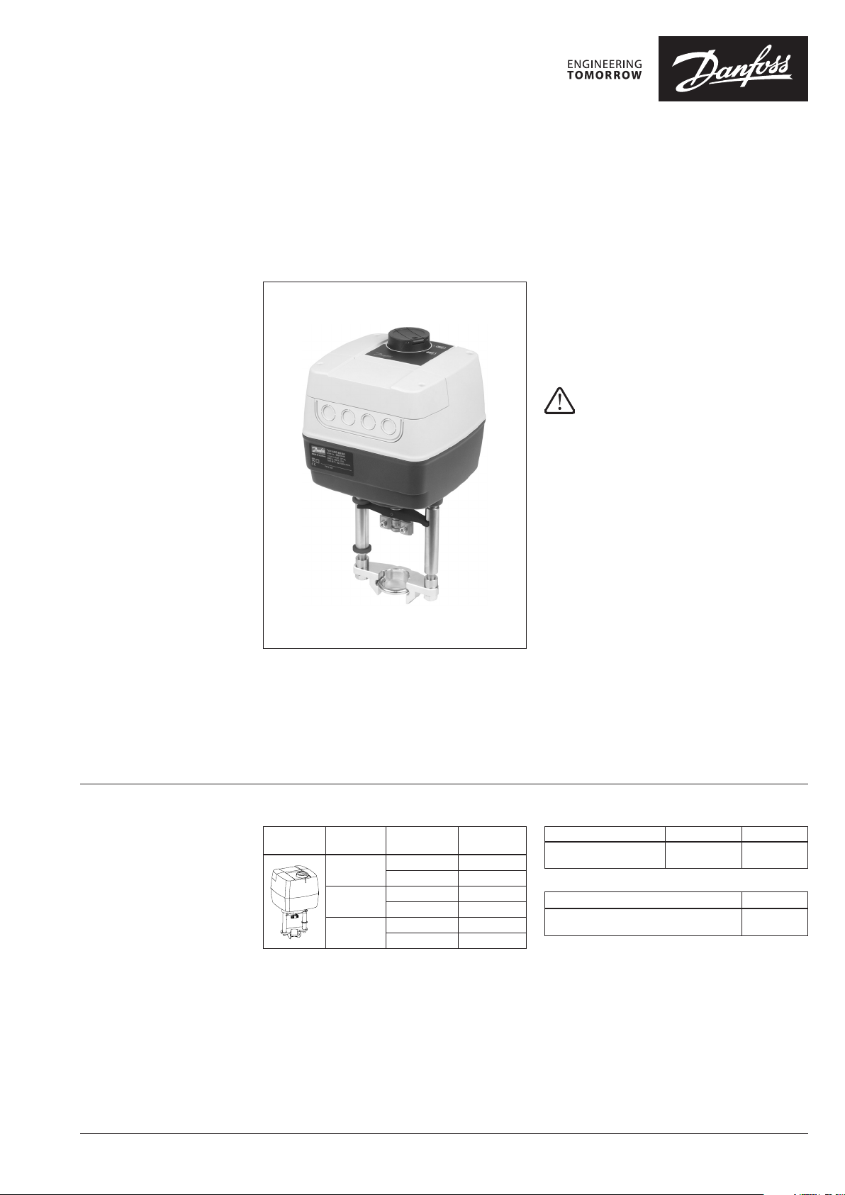
Actuators for 3-point control
AMV 655 – without safety function
AMV 658 SU, AMV 658 SD – with safety function (spring up/down)
Description
Actuators are primarily designed to control the
valve in response to the demand of a controller
in District Heating/cooling, Heating, Ventilating
and Air conditioning systems.
Actuators AMV 655 and 658 can be controlled by
electronic controllers with 3-point output.
Actuators can be used without any adapter in
combination with:
- Valve types VFM, VFS (DN 65-100),
VF (DN 100-150) and VL (DN 100)
- Self-acting flow controller AFQM 6 and
AFQM*.
* With adapter 065B3527 for AFQM 6 or AFQM PN 25, if
produced be fore March 2015.
Used with adapter 065B3527 in
combination with:
- Valve types VFG(S) and VFU.
Features:
• Manual operation mechanical and/or
electrical
• Position indication, LED signalization
• Selectable speed 2 or 6 s/mm
• Integrated auxiliary switch
• External reset button
• 3-point control regulation
• Thermal and overload protection
• Precise control and fast response in 3-point
mode (0.01 s)
Main data:
• Nominal voltage (ac or dc):
- 24 V, 50 Hz/60 Hz
- 230 V, 50 Hz/60 Hz
• Control input signal: 3-point
• Force: 2000 N
• Stroke: 50 mm
• Speed (selectable): 2 or 6 s/mm
• Max. medium temperature: depends on valve
type. (from 150°C up till 300°C)
Ordering
Actuator
Picture Typ e
AMV 655
AMV 658 SU
AMV 658 SD
Power supply
(V)
24 082G3440
230 082G3441
24 082G3446
230 082G3447
24 082G3444
230 082G3445
Code No.
Accessories – Stem heater
Typ e DN Code No.
Stem heater for VFM valve 65-2 50 065Z7022
Accessories – Adapter
Typ e Code No.
Adapter for VFG/S, VFU and AFQM 6 & AFQM
PN 25 if produced before March 2015.
065B3527
© Danfoss | 2022.02 AI195686478583en-010704 | 1
Data sheet Actuators for 3-point control AMV 655/658
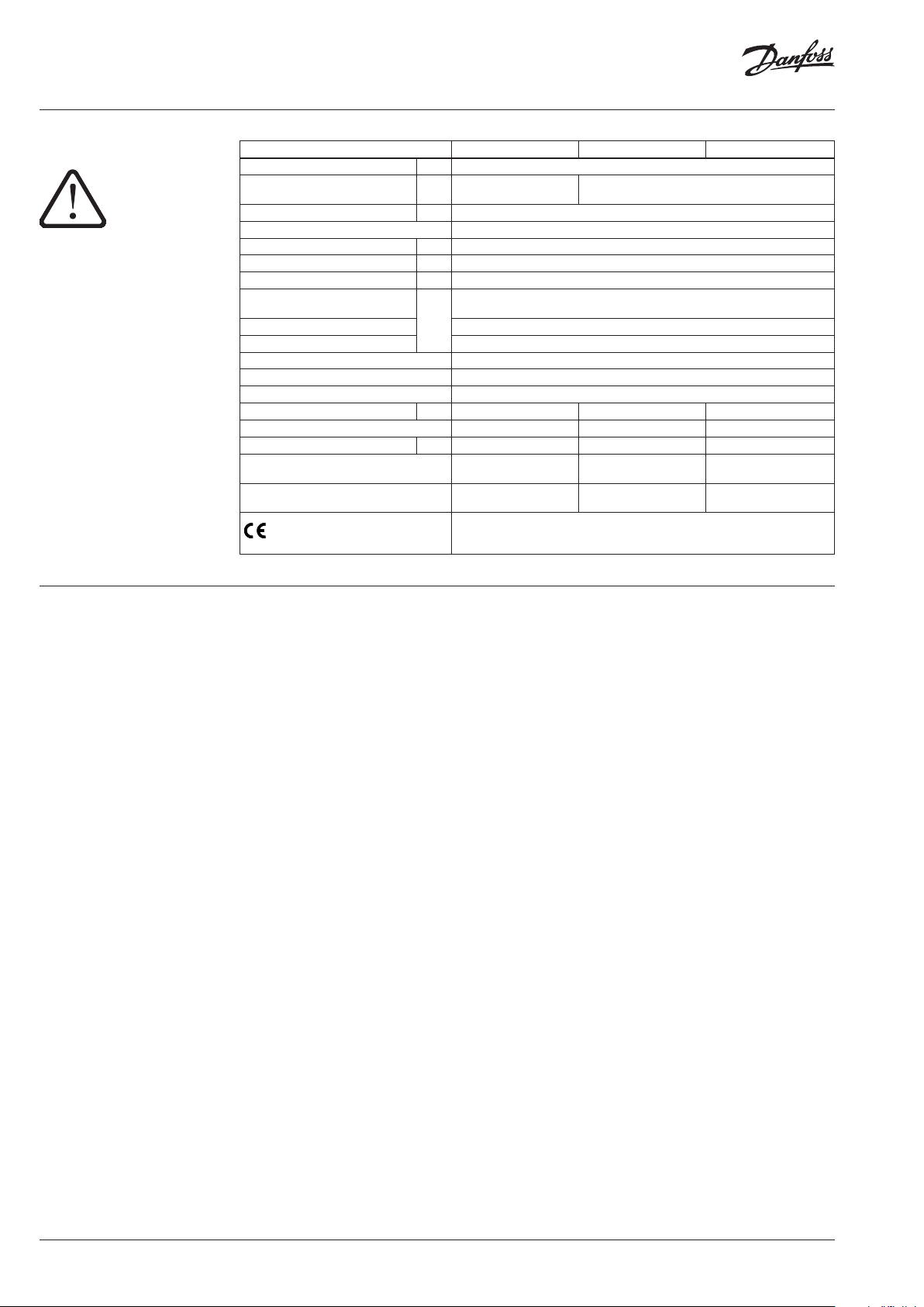
Technical data
Please check power supply
and power consumption prior
connection!
Actuator type AMV 655 AMV 658 SD AMV 658 SU
Power supply V 24 or 230 ; +10 … 15 % ; ac or dc
Power consumption VA
Frequency Hz 50/60
Control input 3-point
Closing force N 2000
Max. stroke mm 50
Speed (selectable) s/mm 2 or 6
Max. medium temperature
Ambient temperature 0 … + 55
Storage and transport temperature −40 … +70 (storing for 3 days)
Humidity 5-95% (no condensing)
Protection class II
Grade of enclosure IP 54
Weight kg 5.3 8.6 8.6
Safety function - Yes Yes
Safety function runtime/50 mm stroke
Manual operation Mechanical
Power failure response
– marking in accordance with the
standards
°C
s - 120 120
12 (24 V)
21 (230 V)
Depends on valve type. No limitations for 150°C (VFS, VF 125 & 150 up to 200°C),
Stem remains in last
Electromagnetic Compatibility Directive (EMC) 2014/30/EU: EN 61000-6-2,
for higher temperature see page 3, INSTALLATION
Electrical and
mechanical
position
Low Voltage Directive (LVD) 2014/35/EU: EN 60730-1, EN 60730-2-14
Safety function extends
the stem
EN 61000-6-3
19 (24 V)
28 (230 V)
Electrical and mechanical
Safety function retracts
the stem
Commissioning
Complete the mechanical and electrical
installation (see instructions) and perform the
necessary checks and tests:
- Turn on the power
- Set the appropriate control signal and check
that the valve stem direction is correct for
the application.
The unit is now fully commissioned.
2 | AI195686478583en-010704 © Danfoss | 2022.02
Data sheet Actuators for 3-point control AMV 655/658
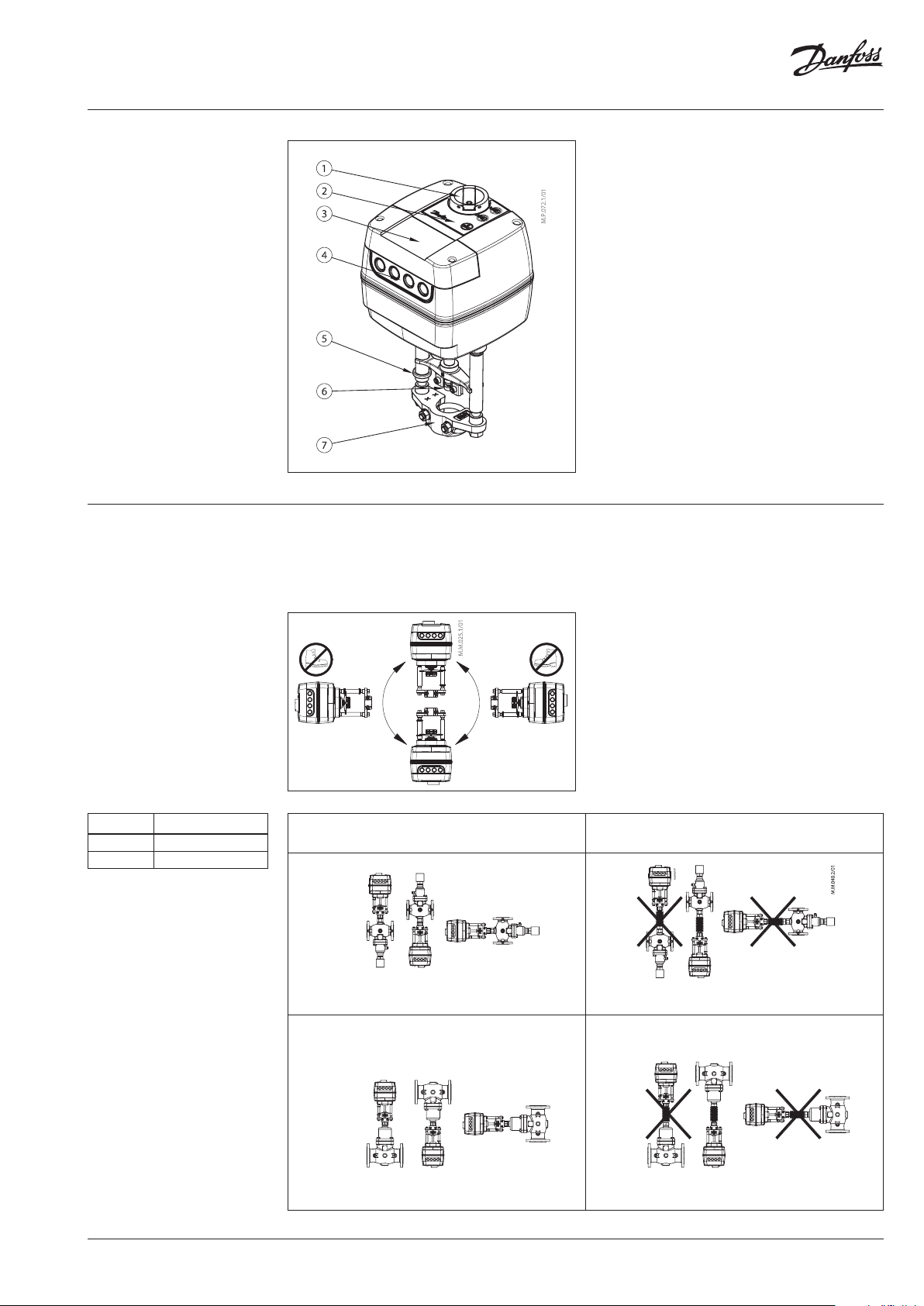
Design
1. Manual operation knob
2. Function buttons
3. Service cover
4. Removable gland support
5. End position indication ring
6. Stem connector
7. Valve connector (yoke)
Installation
ZF 4
ZF 5
Code No.
003G1394
003G1396
Mechanical
Please check the allowed installation positions
for the valve and actuator. The actuator can be
installed in all positions (see below).
<150 °C
Use a M8/SW13 key (not supplied) to fit the
actuator to the valve body. Allow for necessary
clearance for maintenance purposes. To link
valve and actuator stems use a 4mm Allen
key (not supplied). The actuator has position
indication rings which should be pushed
together before el. connection; after self-stroking
they indicate end positions of the stroke.
Electrical connection
Electrical connections can be accessed by
removing the service cover.
Four cable entries
M 20×1.5 cable glands.
are provided for M 16×1.5 or
Note that in order to
maintain the enclosure’s IP rating, appropriate
cable glands must be used.
150 -200 °C ZF 4
200 -350°C ZF5
VFU 2 + adapter 065B3527
VFG/S + adapter 065B3527
VFU 2 + adapter 065B3527 + ZF4/5
VFG/S + adapter 0 65B3527 + ZF4/5
VFGS + adapter 065B3527 + ZF5 (DN 15-125)
AI195686478583en-010704 | 3© Danfoss | 2022.02

Data sheet Actuators for 3-point control AMV 655/658
Wiring
Do not touch any thing on the PCB! Do
not remove the ser vice cover before the
power suppl y is fully switched off.
Max. a llowed curren t output on
termin als 4 and 5 is 4A.
Min. po wer is 3W.
Recommended cross-sectional area
of the wir ing is 1.5 mm
2
AMV 658
AMV 658
AMV 655
24V
230V
SN 0 V Neutral
SP 24, 230 V ac/dc Power supply
4, 5 SP(ac)
1
SP
3
4
SP
5
SP output
-max 4A
-min 3W
Input
24V
230V
AMV 655
SN 0 V Neutral
1, 3 24, 230 V ac/dc Power supply
4, 5
1
4
3
5
1
SP
3
SP output
-max 4A
-min 3W
Input
4 | AI195686478583en-010704 © Danfoss | 2022.02
Data sheet Actuators for 3-point control AMV 655/658
Actuator operating modes
LED signalling
LED operating mode indicator
The three-colour (green/yellow/red) LED
function indicators are located on the actuator
cover. They indicate different operating modes.
• Positioning mode
The actuator is operating automatically. The
stem is extending or retracting according
to the control signal. When positioning is
finished the actuator goes to Stationary
RESET button (versions AMV 658)
mode.
Actuators AMV 658 have external RESET button
which is located on top cover of the actuator
next to LED indicators. With this button you can
• Stationary mode
The actuator is operating without errors.
enter or exit Stand-By mode (press once) See
next paragraph for mode details.
• Error mode
Working temperature is too high - check the
Operating modes
• Stand-By mode (versions AMV 658)
Press the RESET button for 1 sec. to enter
Stand-By mode. The actuator stops in
ambient temperature.
Stroke is too short - check the connection
with valve and valve operation or check if
valve is blocked.
current position and stops responding to
any control signal. Red light is constantly lit.
You can manually operate the actuator with
mechanical handle (version AMV 655/658)
or control buttons (versions AMV 658).
This mode can be very useful during the
commissioning of other equipment, or for
service purposes. To exit Stand-By mode press
the RESET button again.
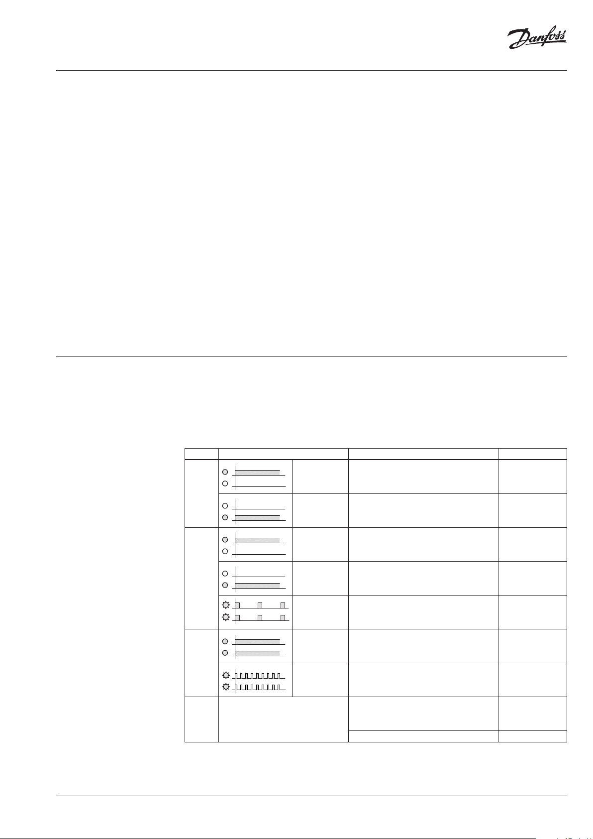
LED indication for AMV 655/658
NOTE! LED signalling is a direct indicator of the signal from controller therefore lengths of LED
indication can vary and sometimes even look like a short flash if the controlling signal is present for a
very short period.
Actuator type AMV 655 doesn’t have constant power supply and operates only when the controller
provides a signal. Therefore limited LED indication possibilities are available.
LED Indication type Operating mode Actuator type
Green
Yellow
Red
Dark No indication
Constantly lit
Constantly lit
Constantly lit
Constantly lit
Flashing Stationary mode AMV 658
Constantly lit Stand - By mode AMV 658
Flashing Error Mode
Positioning mode - Actuator is retracting the
stem
Positioning mode - Actuator is extending the
stem
Stationar y mode - Actuator has reached upper
end position (retracted stem)
Stationar y mode - Actuator has reached bottom
end position (extending stem)
No power supply
No control signal AMV 655
AMV 655
AMV 658
AMV 655
AMV 658
AMV 655
AMV 658
AMV 655
AMV 658
AMV 655
AMV 658
AMV 655
AMV 658
AI195686478583en-010704 | 5© Danfoss | 2022.02

Data sheet Actuators for 3-point control AMV 655/658
DIP switch setting
Manual operation
The actuator has a selection of DIP switches (Fig. 1)
under the service cover.
DIP1: FAST/SLOW – Speed selection
- FAST; 2 s/mm
- SLOW; 6 s/mm
DIP2: DIR/INV – Direct or inverse acting
selector (Fig. 2):
- DIR position; the actuator is direct acting to
input signal.
- INV position; the actuator is (reverse) inverse
acting to input signal.
1
SP
3
Fig. 2
Mechanical and electrical operation are
not allowed to be used at the same time!
The actuator AMV 655 can be manually
positioned and remains in selected position until
it receives signal from the controller.
The actuator AMV 658 can be manually
positioned when in Stand-By mode or when
there is no power supply (mechanically).
Fig. 1
1
3
Actuator type
AMV 655
AMV 658
SP
Mechanical
operation
Electrical
operation
BB
AA
AA
BB
Mechanical manual operation
Actuators AMV 655/658 have a knob & crank
on the top of the housing which enables hand
positioning of the actuator.
Use Mechanical manual operation only when
the power is disconnected.
Electrical manual operation
The actuator AMV 658 has two buttons on the
top of the housing that are used for electrical
manual positioning (up or down) if the actuator
is in Stand-By mode. First press the RESET button
until the actuator goes to Stand-By mode (red
LED is lit). By pressing the upper button
the stem will be extending and by pressing the
lower button the stem will be retracted.
6 | AI195686478583en-010704 © Danfoss | 2022.02

Data sheet Actuators for 3-point control AMV 655/658
Actuator – valves
combinations
AMV 65x +
VFM 2
AME 65x +
VFG + adapter 065B3527 + ZF 4/5
VFGS + adapter 065B3527
+ ZF5 (DN 15-125)
AMV 65x +
VF 2 (DN 100-150)
VL 2 (DN 100)
VFS 2 (DN 65-100)
AMV 65x +
VFU +
adapter:
065B3527 (D N 15-125)
AMV 65x +
VF 3 (DN 100-150)
VL 3 (DN 100)
AMV 65x +
VFG 3 +
adapter:
065B3527 (DN 25-125)
AMV 65x +
AFQM 6 *
* Please use adapte r 065B3527 for combination wi th AFQM PN25 & AFQM 6 if produced before Ma rch 2015.
AMV 65x +
AFQM PN 16 (DN 65-125)
AMV 65x +
AFQM PN 25 *
AI195686478583en-010704 | 7© Danfoss | 2022.02

Data sheet Actuators for 3-point control AMV 655/658
Dimensions
191
369
353
Min. 450
186
© Danfoss | DCS-SGDPT/SI | 2022.028 | AI195686478583en-010704
 Loading...