


Data sheet
Actuators for three point control
AMV 55, AMV 56
Description
The actuators are used with valves:
• VFM2 (DN 65-150) only in combination with
AMV 55,
• VFS 2 (DN 15-50) only in combination with
AMV 56 and clutch 065Z7551,
• VFS 2 (DN 65-100),
• VL 2/3 (DN 100),
• VF 2/3 (DN 100-150),
•
VL 2/3 & VF 2/3 (DN 65, 80) only in combination
with AMV 56 and adapter 065Z0312,
• AFQM (DN 65-125) and AFQM 6 (DN 40-50).
Features:
• Load related “switch off“ function that
prevents overloading
• Optional auxiliary switches, feedback
potentiometer and valve stem heater are
available.
Main data:
• Nominal voltage:
24 VAC 50/60 Hz,
230 VAC 50/60 Hz,
• Control input signal: 3 point
• Force:
2000 N (AMV 55),
1500 N (AMV 56)
• Stroke: 40 mm
• Speed:
8 s/mm (AMV 55),
4 s/mm (AMV 56)
• Max. medium temperature: 200 °C
• Manual operation
Ordering Actuators
Typ e Power supply Code No.
AMV 55 24 VAC 082H3020
AMV 55 230 VAC 082H3021
AMV 56 24 VAC 082H3023
AMV 56 230 VAC 082H3024
Accessories
Typ e
Potentiometer (10 kΩ/30 mm)
Potentiometer (10 kΩ/40 mm)
Potentiometer (1 kΩ/30 mm)
Potentiometer (1 kΩ/40 mm)
Additional switches (2×)
Stem heater 24 V AC/DC
(VF, VL valves DN 65-80)
Stem heater 24 V AC/DC
(VF, VL valves DN 100 and
VFS2 valves DN 15-50)
Stem heater 24 V AC/DC (VF valves
DN 125, 150 and VFS valves DN 65-100)
AMV 56 adapter (VF, VL valves DN 65,80)
AMV 56 clutch (VFS 2 DN 15-50)
1)
only one potent. or add. switches can be added)
1)
Code No.
082H7035
082H7036
082H7038
082H7039
082H7037
065Z0 315
065Z7020
065Z7022
06 5Z0312
065Z7551
© Danfoss | 2016.10
VD.IR.R1.02 | 1
Data sheet Actuators for three point control AMV 55, AMV 56
Technical data
Typ e AMV 55 AMV 56
Power supply V 24, 230; ± 10 %
Power consumption VA 7 17, 5
Frequency Hz 50/60
Control input 3-point
Close of force N 2000 150 0
Max. stroke mm 40
Speed s/mm 8 4
Max. medium temperature
Ambient temperature 0 … 55
Storage and transport temperature –40 … 70
Ambient humidity 95 % r.h., non-condensing
Protection class I (230 V); III (24 V)
Grade of enclosure IP 54
Weight kg 3,8
- marking in accordance with the standards
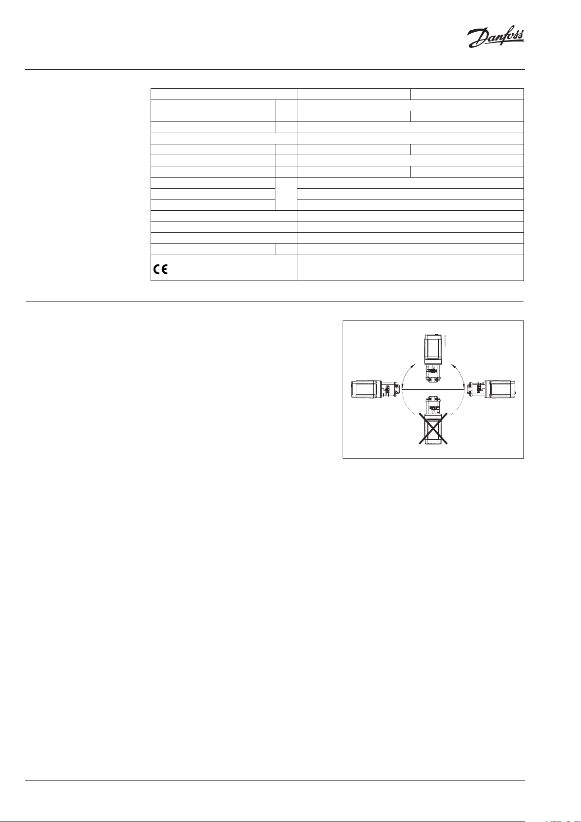
Installation Mechanical
The actuator should be mounted with the valve
stem (use a 4 mm Allen key -not supplied) in
either horizontal position or pointing upwards.
Use a M8/SW13 key (not supplied) to fit the
actuator to the valve body. Allow for necessary
clearance for maintenance purposes.
The valve has position indication rings
which should be pushed together before
commissioning; after stroking they indicate the
ends of the stroke.
Electrical
Electrical connections can be accessed by
removing the cover. Two M16 × 1,5 cable entries
are provided. Both entries are provided with a
rubber grommet for use with flexible cable. Note
that in order to maintain the enclosure IP rating,
appropriate cable glands must be used.
200
°C
Low Voltage Directive (LVD) 2014/35/EU: EN 60730-1, EN 60730-2-14
Electromagnetic Compatibilit y Directive (EMC) 2014/30/EU: EN 61000-6-2,
EN 61000-6-3
Disposal The actuator must be dismantled and the
elements sorted into various material groups
before disposal.
2 | VD.IR.R1.02
© Danfoss | 2016.10

Data sheet Actuators for three point control AMV 55, AMV 56
Wiring
24 V AC, 230 V AC, 50/60 Hz
1 0 V Neutral
2
230 Vac version:
Do not touch anything on
the PCB! Lethal voltage!
Input
power
supply
3
4
5
082H3020
082H3023
082H3021
082H3024
2
4
3
5
24 V
230 V
Output
Two additional switches 2S
Commissioning The following mechanical and electrical
installation and the necessary checks and tests
are to be completed in order to commission the
unit:
- Turn on the power.
- Set the appropriate control signal and
check the valve stem direction is correct for
the application.
The unit is now fully commissioned.
Manual override
Additional potentiometer P
The manual override is applied by rotating the
4 mm Allen key (not supplied) to the required
position. Observe the direction of the rotation
symbol.
• Disconnect control signals
• Adjust valve position using an Allen key
• Set valve to closed position
• Restore control signals
© Danfoss | 2016.10
VD.IR.R1.02 | 3

Danf
already on order pro
All trademarks in this material are property of the respec
Data sheet Actuators for three point control AMV 55, AMV 56
Dimensions
120
min 478
325
55
Actuator - valve
combinations
AMV 56 +
VL 2, VF 2 (DN 65-8 0) +
adapter 065Z 0312
VL 3, VF 3 (DN 65, 80) +
adapter 065Z 0312
AMV 55 +
VFM 2 (DN 65-150)
AMV 56 +
VFS 2 (DN 15-50) +
clutch 065Z 7551
AMV 55, AMV 56 +
VL 2 (DN 100)
VF 2 (DN 100-150)
AMV 56 +
AMV 55, AMV 56 +
VFS 2 (DN 65-100)
AMV 55, AMV 56 +
VL 3 (DN 100)
VF 3 (DN 100-150)
AMV 55, AMV 56 +
AFQM (DN 65-125)
AFQM 6 (DN 40 -50)
oss can accept no responsibility for possible errors in catalogues, brochures and other printed material. Danfoss reserves the right to alter its products without notice. This also applies to products
vided that such alterations can be made without subsequential changes being necessary eady agreed.
4 | VD.IR.R1.02
tive companies. Danfoss and the Danfoss logotype are trademarks of Danfoss A/S. All rights reserved.
© Danfoss | DHS-SRMT/SI | 2016.10
 Loading...