

Data sheet
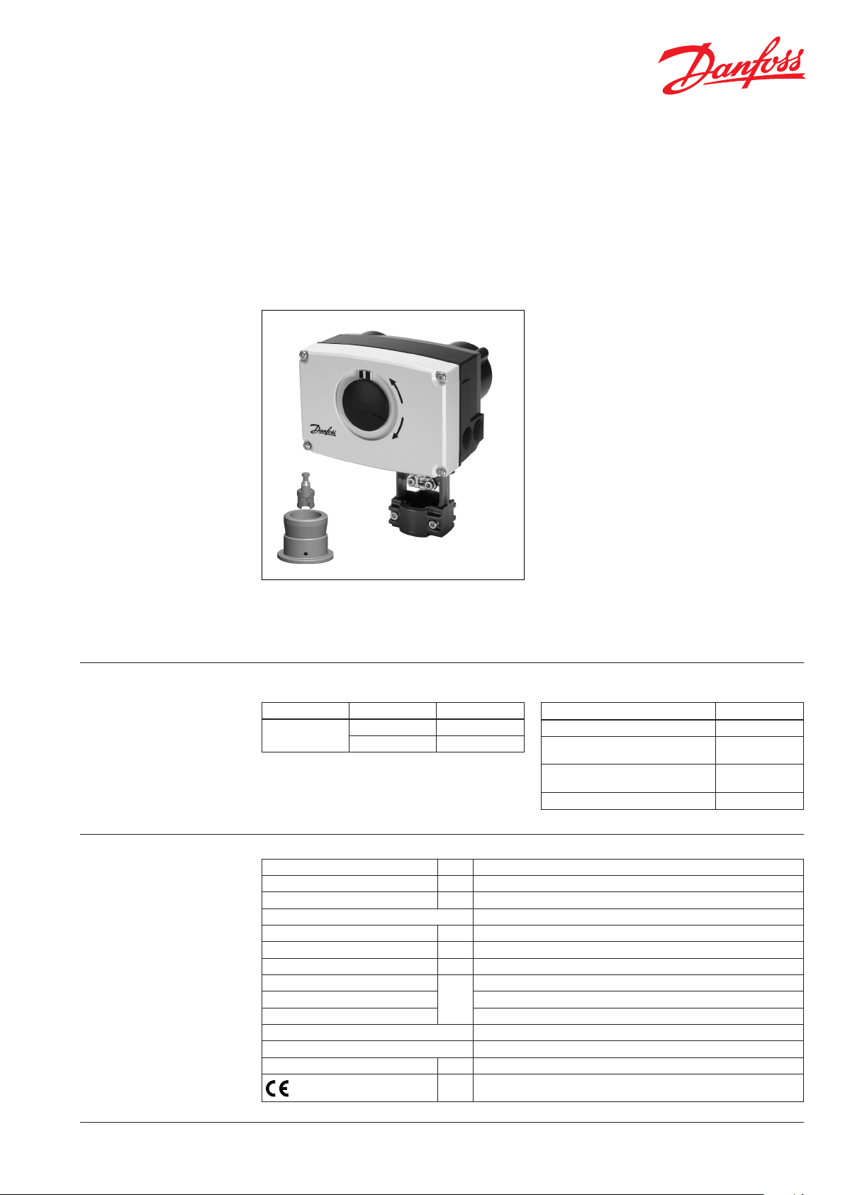
Actuator for three point control
AMV 438 SU – safety function (spring up)
Description
AMV 438 SU actuator is used with two and
three-way valves type VRB, VRG, VF and VL up to
DN 50 diameter.
Ordering Actuator
Typ e Supply voltage Code No.
AMV 438 SU
24 VAC 082H 0122
230 VAC 082H0123
The actuator has some special features:
• advanced design incorporates load related
‘switch-o’ to ensure that actuators and
valves are not exposed to overload
• Safety function (spring up): In case of power
failure or power switch o spring up function
retracks actuator stem to end position.
Further manual stem positioning is not
disabled.
Main data:
• Nominal voltage:
- 24 VAC, 50 Hz/60 Hz
- 230 VAC, 50 Hz/60 Hz
• Control input signal:
3 point
• Force: 450 N
• Stroke: 15 mm
• Speed: 15 s /mm
• Max. medium temperature: 150 °C
• End-position signals
Accessories
Typ e Code No.
Additional switches (2×) 082H7015
Additional switches (2×)
and potentiometer (10 kΩ)
Additional switches (2×)
and potentiometer (1 kΩ)
Stem heater (for valves DN 15-50) 065Z0315
082H7016
08 2H7017
Technical data
DH -SM T/SI
Power supply V 24 AC, 230 AC; +10 to –15%
Power consumption VA 12
Frequency Hz 50/60
Control input 3-point
Close of force N 450
Max. stroke mm 15
Speed s/mm 15
Max. medium temperature
Ambient temperature 0 … 55
Storage and transport temperature –40 … +70
Protection class I (230 V); III (24 V)
Degree of protection IP 54
Weight kg 2.3
- marking in accordance with
standards
VD.LE.P4.02 © Danfoss 09/2015
°C
Low Voltage Directive (LVD) 2006/95/EC: EN 60730-1, EN 60730-2-14
EMC Directive 2004/108/EC: EN 61000-6-2, EN 61000-6-3
150
1
Data sheet Actuator for three point control AMV 438 SU
Installation Mechanical
Use 4 mm Allan key (not part of actuator
delivery) to mount actuator on the valve.
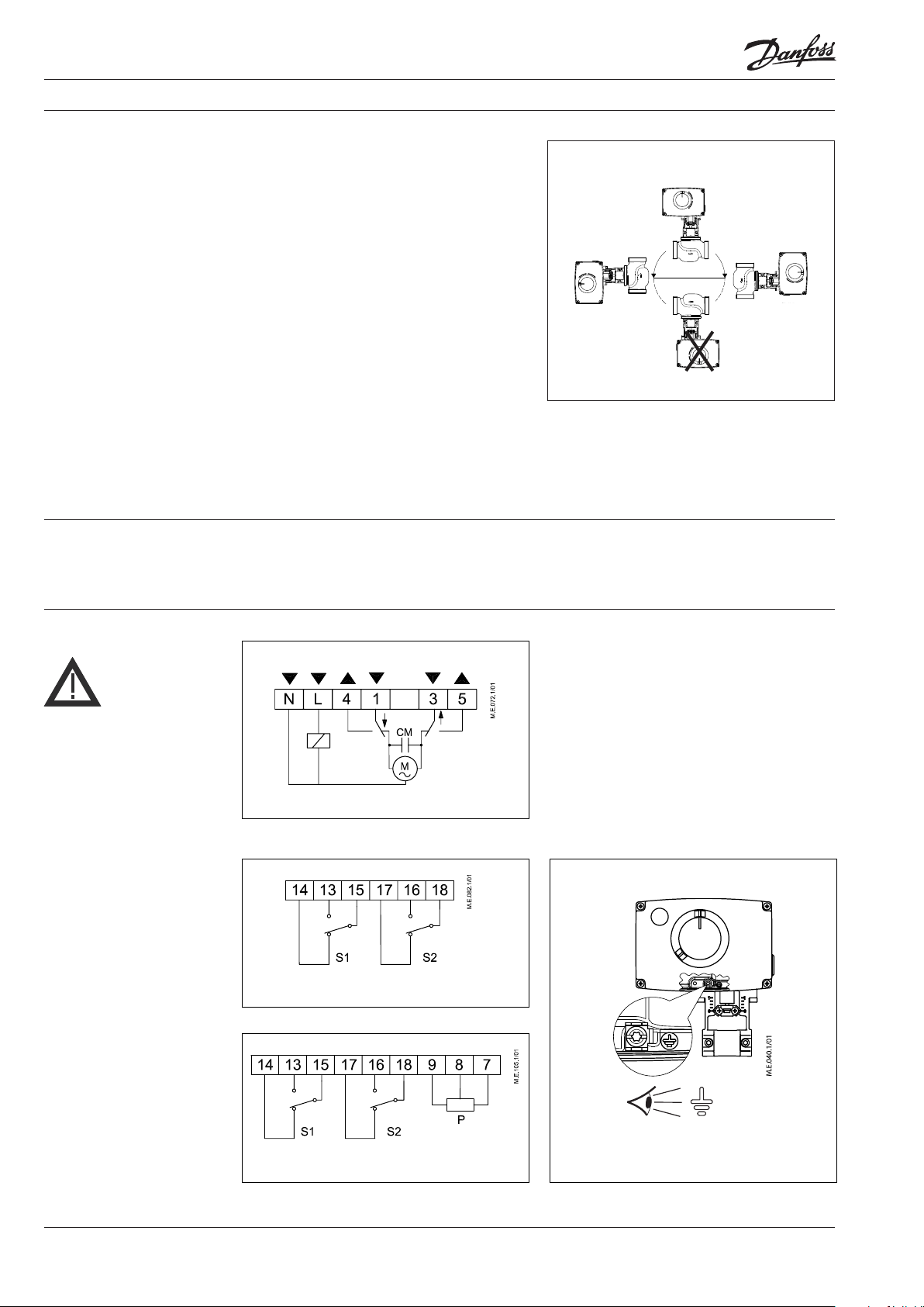
Installation of the valve with the actuator is
allowed in horizontal position or upwards.
Installation downwards is not allowed.
The actuator must not be installed in an
explosive atmosphere, at ambient temperature
lower than 0 °C or at ambient temperature higher
than 55 °C. It must not be subject to steam jets,
water jets or dripping liquid as well.
Note: the actuator may be rotated up to 360° with
respect to the valve stem by loosening the retaining
xture. Once the actuator is placed, retighten the
xture.
Electrical
Electrical connections can be accessed by
removing the actuator cover. Two cable gland
entries with thread (M20 x 1.5 and M16 x 1.5) are
prepared for cable glands.
Disposal The actuator must be dismantled and the
elements sorted into various material groups
before disposal.
Wiring
230 VAC version:
Do not touch anything on the
PCB!
Do not remove the cover
before the power supply is fully
switched o.
Accessories
Note: Cable and cable gland used must not
compromise the actuator’s IP rating, and must
ensure the connectors are fully strain relieved.
Please observe local rules and regulations as well.
Terminals 1, 3:
Control voltage input from the controller.
Terminals 4, 5:
Output used for position indication or
monitoring.
L
Power supply 24 V~ or 230 V~
N
Common (0 V)
Additional switch (2x)
230V
Additional switch (2x) and potentiometer
2
VD.LE.P4.02 © Danfoss 09/2015
DH -SMT/S I

Data sheet Actuator for three point control AMV 438 SU
Commissioning
Manual override
Complete the mechanical and electrical
installation and perform the necessary checks
and tests:
• Apply power
• Apply the appropriate control signal and
check that the valve stem direction is correct
for the application
The unit is now fully commissioned.
Manual override is done by means of positioning
spindle inside the actuator:
• Disconnect power signal
• Remove the actuator cover
• Insert 5 mm Allan key (not part of actuator
delivery) into the top of the positioning spindle
• Turn the key against the spring (observe the
rotation direction)
To hold a manual override position, the key must
be wedged.
After manual override is not needed:
• Restore power signal.
5 mm
Safety function
The safety function will fully close the valve. The
safety function unit is factory tted to the rear of
the actuator.
Valve type Safety action will close port A-AB
VRG, VRB SU
VL (DN 15-50) SU
VF (DN 15-50) SU
or
VL 2, VF 2 VL 3, VF 3, VRG 3, VRB 3
=
SU
DH -SMT/S I
VD.LE.P4.02 © Danfoss 09/2015
3

Data sheet Actuator for three point control AMV 438 SU
Dimensions
Adapter
065Z0311
Actuator - valve
combinations
AMV 438 SU + AMV 438 SU + AMV 438 SU + AMV 438 SU +
VRB 2, VRG 2 VRB 3, VRG 3 VF 2, VL 2 VF 3, VL 3
(DN 15-50) (DN 15-50) (DN 15-50) (DN 15-50)
4
VD.LE.P4.02
Produce d by Danfoss A/S © 09/2015
 Loading...