

Data sheet
Actuators for three point control
AMV 130, AMV 140, AMV 130H, AMV 140H
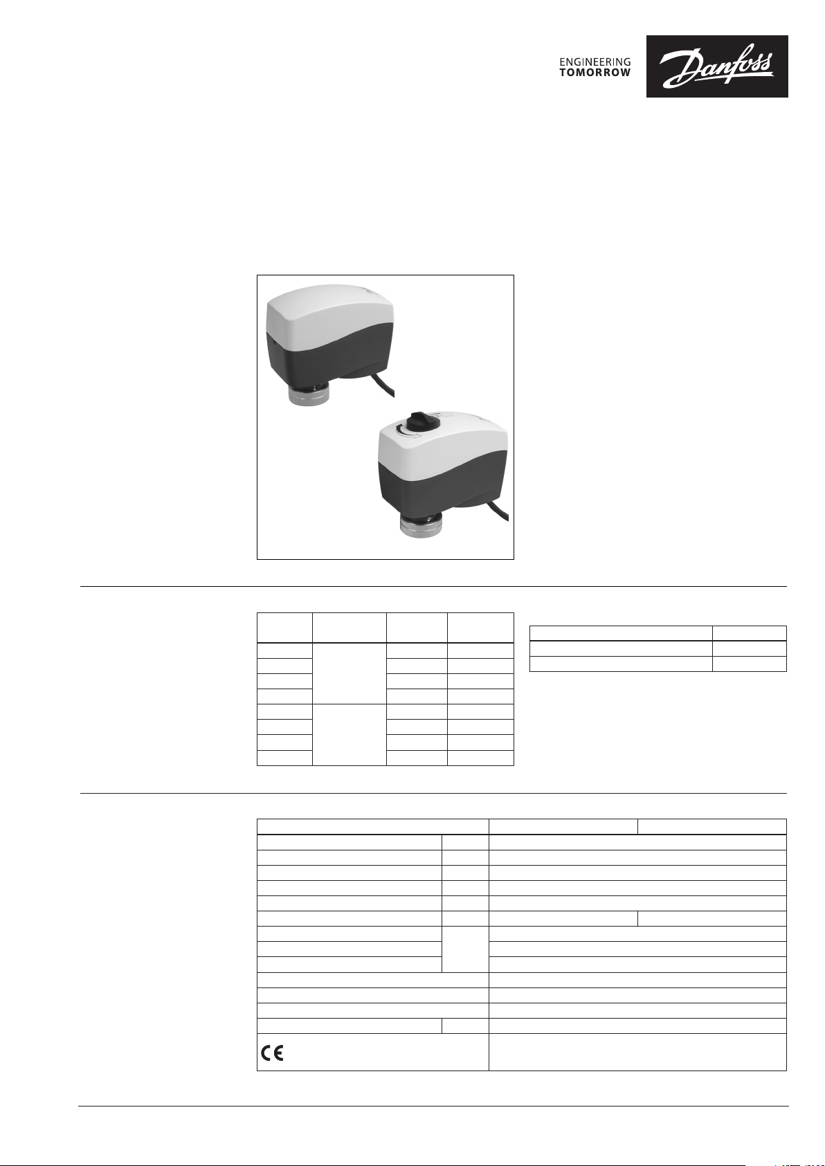
Description
Ordering
AMV 130, AMV 140
AMV 130H, AMV 140H
Typ e
AM V 130
AMV 140 12 082H8038
AM V 130H 24 082H8040
AMV 140H 12 082H8042
AM V 130
AMV 140 12 082H8039
AM V 130H 24 082H8041
AMV 140H 12 082H8043
Supply voltage Speed
V AC s/mm
24 082H8036
24
24 082H8037
230
Code No.
AMV 130/140 and AMV 130H/140H actuators are
used with:
• VZ DN 15, 20,
• VZL DN 15, 20 with stem extension plug or
• AHQM (DN 15-32) valves.
The actuator can be used with fan coil units,
induction units, small reheaters, recoolers and
zone applications in which hot/cold water is the
controlled medium.
Main data:
• 3-point versions
• Force switch-off at stem down position
prevents overload of actuator and valve
• No tools required for mounting
• Maintenance free during lifetime
• Low noise operation
• Supplied with 1.5 m cable
Spare parts
Typ e
Cable (5m) - 24 V
Cable (5m) - 230 V
Code No.
082H8052
082H8053
Technical data
© Danfoss | 2017.03
Typ e AMV 130, AMV 130H AMV 140, AMV 140H
Power supply
Power consumption
Frequency
Close of force
Stroke
Speed
Max. medium temperature inside the pipe
Ambient temperature 0…55
Storage and transport temperature –40…70
Ambient humidity 95 % r.h., non-condensing
Protection Class II
Grade of enclosure IP 42
Weight
- marking in accordance with standards
V
VA
Hz
N
mm
s/mm
°C
kg
Low Voltage Directive (LVD) 2014/35/EU: EN 60730-1, EN 60730-2-14
Electromagnetic Compatibility Directive (EMC) 2014/30/EU:
EN 61000-6-2, EN 61000-6-3
24 AC, 230 AC; +10 to –15 %
1-24 V AC; 8-230 V AC
50/60
200
5.5
24 12
130
0.3
VD.KG.Y3.02 | 1
Data sheet AMV 130, AMV 140, AMV 130H, AMV 140H
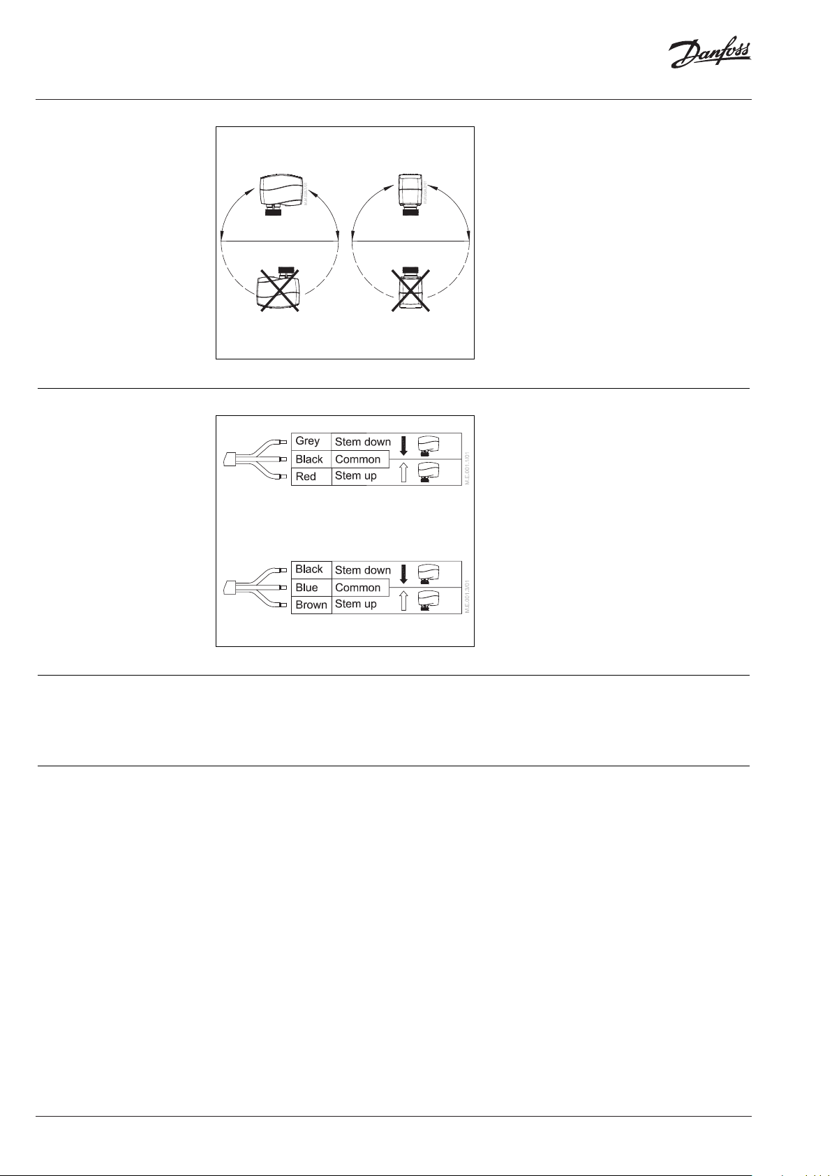
Installation
Wiring
Mechanical
The actuator should be mounted with the valve
stem in either horizontal position or pointing
upwards.
The actuator is fixed to the valve body by means
of a mounting ring which requires no tools for
mounting. The ring should be tightened by
hand.
Electrical
Important: It is strongly recommended that the
mechanical installation is completed before the
electrical installation.
Each actuator is supplied with the connecting
cable for the controller.
AMV 130/140, AMV 130H/140H - 24V
Disposal
Commissioning
AMV 130/140, AMV 130H/140H - 230V
The actuator must be dismantled and the
elements sorted into various material groups
before disposal.
The factory setting of the spindle is the fully
stem up position because of easier mechanical
connection of the actuator on the valve.
2 | VD.KG.Y3.02
© Danfoss | 2017.03

Data sheet AMV 130, AMV 140, AMV 130H, AMV 140H
Installation and
commissioning procedure
(if required)
Do not touch anything on
the PCB! Before removing the
cover in need of hand operation
with Allen key power supply
must be disconnected. Lethal
voltage!
Manual override
(for service purposes only)
1 Check the valve’s neck. The actuator should
be in steam up position (factory setting).
Ensure that the actuator is mounted securely
on the valve body.
2 Energise the actuator according to the wiring
diagram - see page 2.
3 The direction of stem movement can be
observed on the position indicator.
AMV 130, AMV 140
1 Remove the cover.
❶
①
②
➋➌
position
indicator
Allen key 6mm
Caution:
Do not manually operate the
drive under power!
2 Insert the Allen key 6 into the spindle.
3 Press and hold the button (on the bottom side
of the actuator) during manual override.
4 Pull out the tool.
5 Place cover back on the actuator.
Remark:
A ”click” sound after energizing the actuator
means that the gear wheel has jumped into
normal position.
AMV 130H, AMV 140H
1 Press and hold the button (on the bottom side
of the actuator) during manual override.
Remark:
A ”click” sound after energizing the actuator
means that the gear wheel has jumped into
normal position.
➍
❶
push
❺
❷
© Danfoss | 2017.03
VD.KG.Y3.02 | 3

Danf
already on order pro
All trademarks in this material are property of the respec
Data sheet AMV 130, AMV 140, AMV 130H, AMV 140H
Actuator - valve
combinations
Remark: VZL valves with stem e xtension
plug
Dimensions
AMV 130(H)/140(H)
+ VZ 2 / VZL 2
88
AMV 130, AMV 140
AMV 130(H)/140(H)
+ VZ 3 / VZL 3
5092
74
AMV 130(H)/140(H)
+ VZ 4 / VZL 4
92
94
AMV 130H, AMV 140H
AMV 130(H)/140(H)
+ AHQM (DN 15-32)
50
74
oss can accept no responsibility for possible errors in catalogues, brochures and other printed material. Danfoss reserves the right to alter its products without notice. This also applies to products
vided that such alterations can be made without subsequential changes being necessary eady agreed.
4 | VD.KG.Y3.02
tive companies. Danfoss and the Danfoss logotype are trademarks of Danfoss A/S. All rights reserved.
© Danfoss | DHS-SRMT/SI | 2017.03
 Loading...