

Operating Guide
Travel Speed
10 (12) s/mm
AMV 120 NL-1
AMV 120 NL-1 / 73694410
❶
Ste m Trav el 5 mm
MAINTENANCE
FREE
5-95 % RH
no condensing
AMV 120 NL-1 +
AB-QM
=
=
AUTO
4 – 6 mm × 1 mm
AQ315258770192en-010301 | 1© Danfoss | 2021.09
AMV 120 NL-1
❷
AMV 120 NL-1
SN 4 1 3 5
AC 24 V
Connect via safety isolating transformer.
❸
~ AC 24V
50/60Hz
(Oponal)(Oponal)
½”
❹
⑤
①
④
③
⑤
②
①
①
②
②
①
AMV 120 NL-1 +
AB-QM
AQ315258770192en-010301 2 | © Danfoss | 2021.09

AMV 120 NL-1
ENGLISH
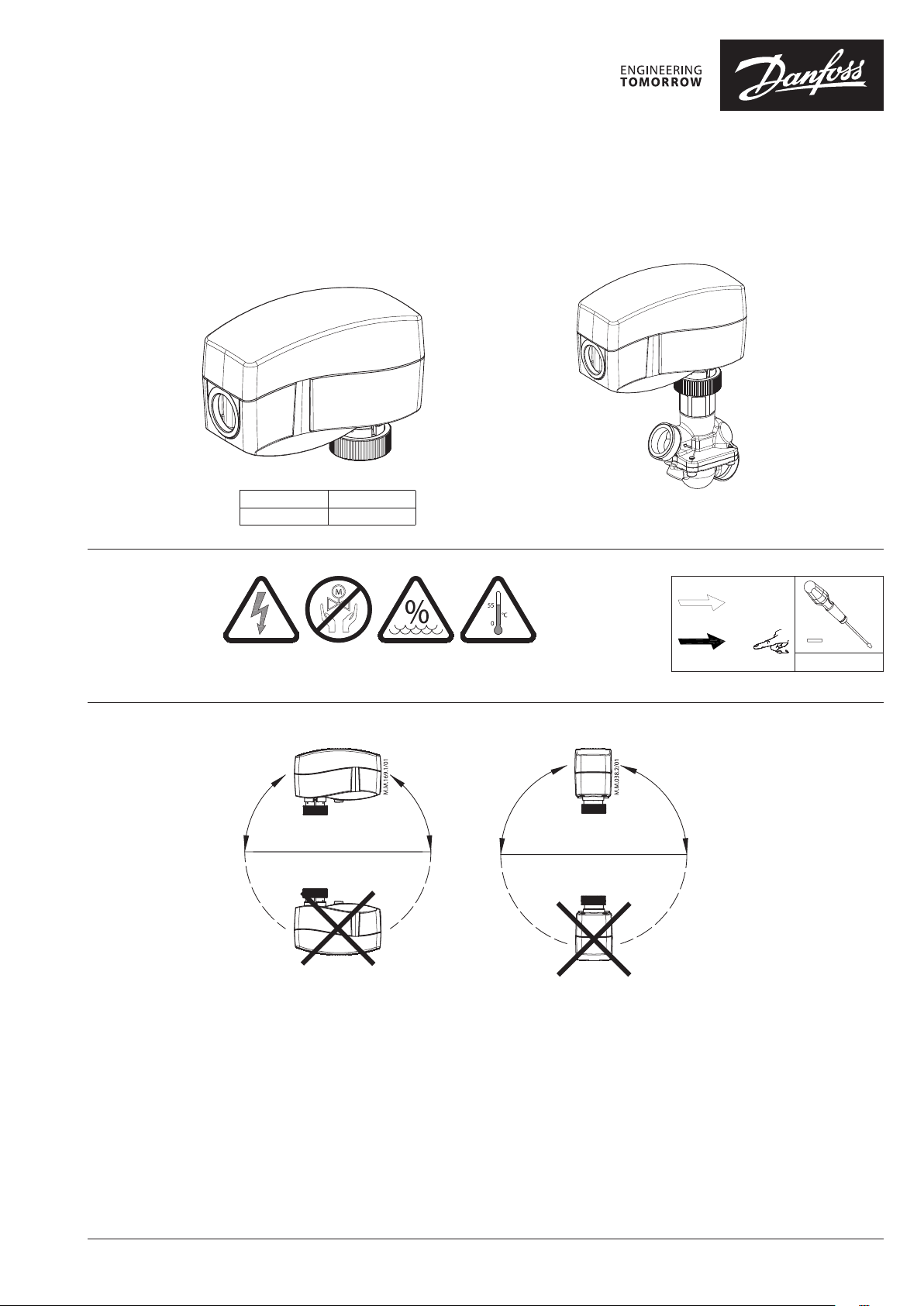
Safety Notes
To avoid personal injury and damage to
the device or other property, it is
necessary to read and follow these
instructions carefully.
Assembly, start-up, and maintenance work
must be performed by qualified and authorized
personnel.
Comply with the instructions of the system
manufacturer or system operator.
Do not remove the cover befo re the
power supply is switche d off.
Mounting Position ❶
The actuator should be mounted with the valve
stem in either a horizontal position or pointing
upwards.
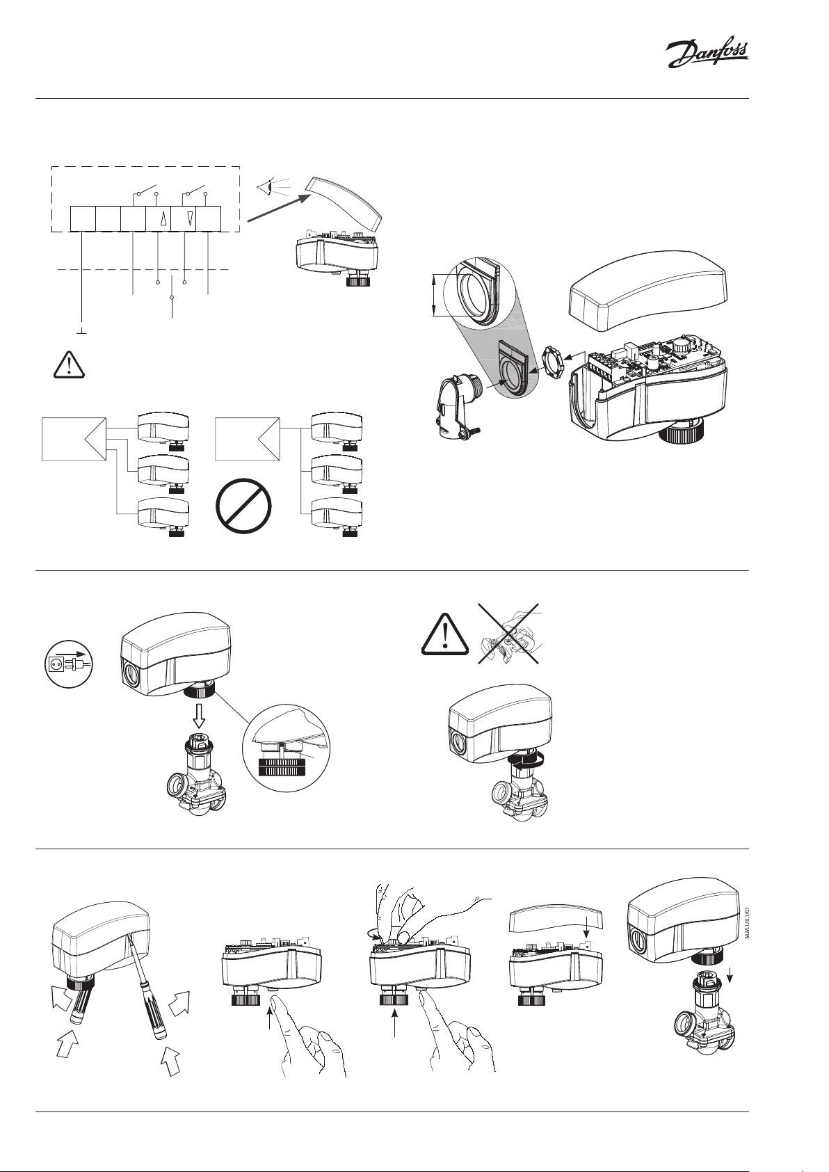
Wiring ❷
AC 24 V
Connect via Class 2 (Nor th America)
or Safety E xtra-Low Voltage (SELV)
(Europe). Failure to comply can lead to
equipment damage or personal injury.
- Remove cover ①
- Press and hold the button (on the bottom
side of the actuator) ② during manual
override ③
- Replace cover ④
- Install actuator on valve ⑤
Remark:
A ‘click’ sound af ter energizing the actuator
indicates that the gear wheel has jumped into
normal position.
Don’t di smount the ac tuator from
the valve whe n it is in a stem do wn
position!
If dismounted in a stem down p osition, there is a
high risk that the actuator g ets stuck.
Switch off power be fore wiring the
actuator!
1. Make all wiring connections in accordance
with local, national, or regional regulations.
2. For applications requiring conduit, a field
supplied 1/2” trade size electrician’s fitting
and lock nut can be mounted in the actuator
enclosure. Use flexible metallic tubing or its
equivalent with the field supplied fitting.
3. Insert wiring material through the removable
plug or conduit fitting, and connect to the
terminal block using the applicable wiring
diagram ❷.
4. Optionally, end position feedback is
available on terminal 4 (stem down) and
terminal 5 (stem up). Both contacts are
normally open.
Installation ❸
1. Check the valve neck. The actuator should
be in the full up position ① (factory setting).
If it is not, refer to the manual override
instructions and reposition the actuator to
its full up position ❸①.
2. The actuator is fixed to the valve body by
means of a ribbed nut which requires no
tools for mounting. The ribbed nut should
be hand tightened only.
Manual override ❹
(for service purposes only)
Do not use the manual over ride if
power is connected!
© Danfoss | 2021.09 | 3AQ315258770192en-010301

AMV 120 NL-1
ІМПОРТЕР:
UA: ТОВ з ІІ «Данфосс ТОВ», вул. Вікентія Хвойки, 15/15/6, м. Київ, 04080, Україна
73694410 / AQ315258770192en-0103014 | © Danfoss | DCS-S/SI | 2021.09
 Loading...