

Page 1
Data sheet Built-in motor module AMER
Application AMER is used with a Pt 1000 Ω sensor.
A remote control for setting or parallel
displacement of required temperature can be
connected.
Nine slave motors mitte AMES modules can
be connected to the AMER module.
Total range, control voltage range and motor
travel direction are selected in using DIPswitches.
AMER has override facility controlled by a
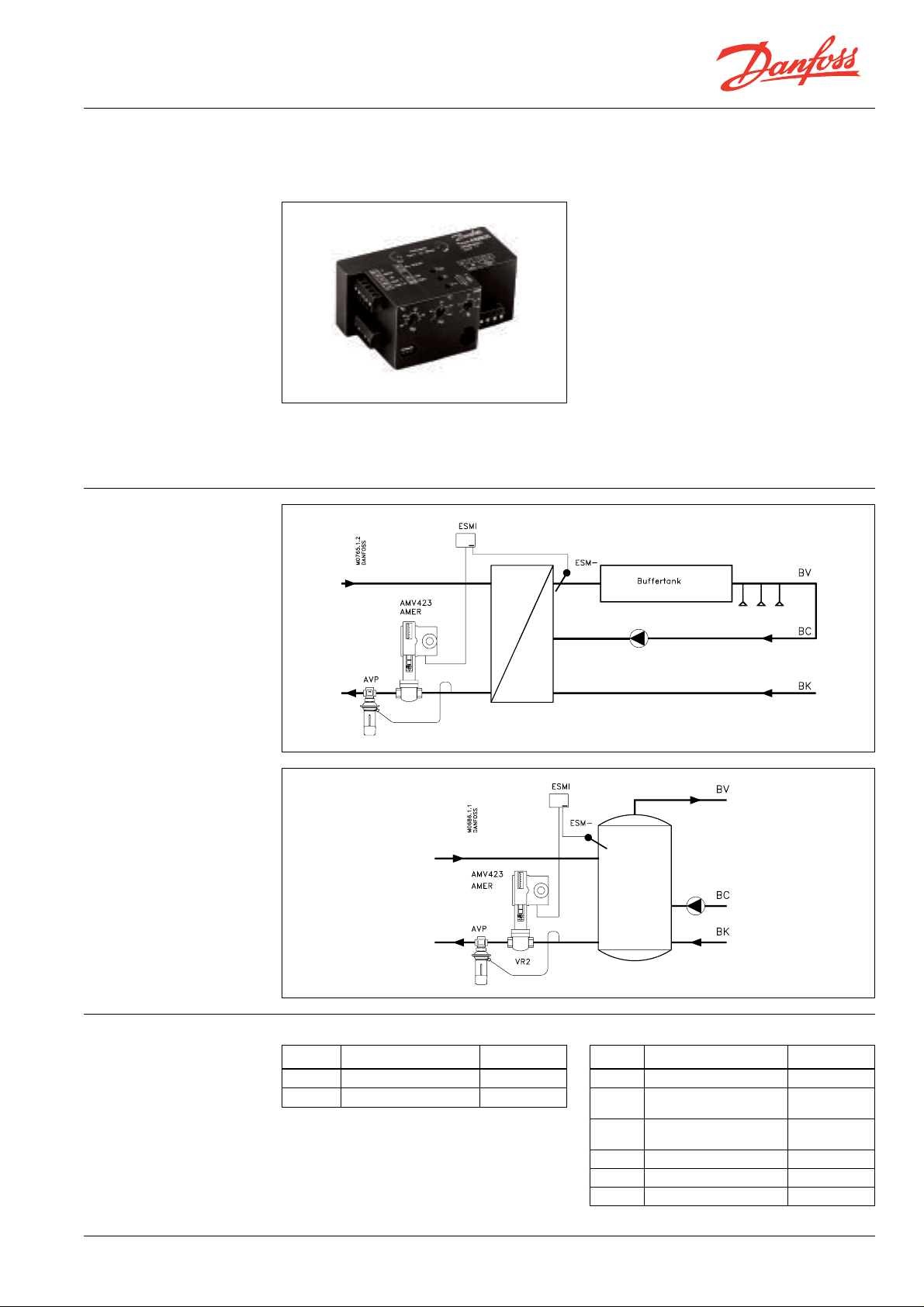
Motor module AMER is a P or PI control, for
storage tank or heat exchanger control.
The module is mounted directly in the motors
type AMV 323, AMV 423 and AMV 523.
Principle
time switch or a manual switch. AMER is
available in 24 V and 230 V versions.
Ordering
BC-HM ED.95.T1.02 © Danfoss 9/95 1
Motor modules
Type Supply voltage Code no.
AMER 24 V ~ 082B3318
AMER 230 V ~ 082B3319
Pt 1000
Ω
sensor
Type Description Code no.
ESMA Surface sensor 084N1004
ESMU
ESMU
ESMR Room sensor 084N1016
ESMB Universal sensor 087N0010
ESMI Remote control 084N1018
Immersion sensor,
100 mm pocket
Immersion sensor,
250 mm pocket
084N1008
084N1009
Page 2
Data sheet Built-in motor module AMER
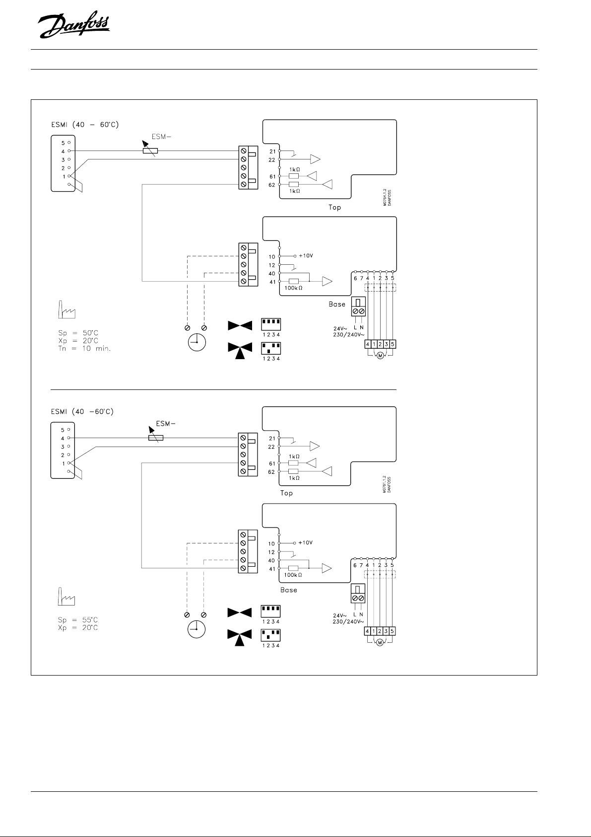
Wiring
PI control
Terminals 6 and 7:
Supply voltage
Terminals 1, 2, 3, 4 and 5:
Supply voltage from AMER to
motor terminal board.
Terminals 21, 22:
Connection for Pt 1000 Ω
sensors.
Terminal 61:
0 - 10 V output signal for
P control.
Terminal 62:
0 - 10 V output signal for
PI control.
Terminal 10:
10 V output.
Terminal 12:
Common (0 V d.c.).
Terminal 40/41:
Input for control voltage from
terminal 61 or 62 (P or PI
control).
Input 40 has higher priority
than input 41.
If override is required, control
signal must be connected to
terminal 41. Terminal 40 can
then be used to connect
motor override unit , e.g. a
frost protection thermostat.
On removing potential from
terminal 40 (using a contact)
override is cancelled.
P control
2 ED.95.T1.02 © Danfoss 9/95 BC-HM
Page 3

Data sheet Built-in motor module AMER
Setting
24 V~
3-lead connection
230V~
3-lead connection
Parallel connection of motors with AMES to common AMER controller (toal max. number
of motors: 10).
A
Factory setting.
Motor runs up on rising control
voltage
Ust = 0 - 10 V
Use settings A or B. Other settings can be used in more special systems, e.g. systems with cascade
control.
B
Motor runs down on rising
control voltage
Ust = 0 - 10 V
E
As A but with control voltage
Ust = 0 - 5 V
F
As A but with control voltage
Ust = 0 - 5 V
BC-HM ED.95.T1.02 © Danfoss 9/95 3
G
As A but with control voltage
Ust = 5 - 10 V
H
As B but with control voltage
Ust = 5 - 10 V
Page 4

Data sheet Built-in motor module AMER
Data
Mounting
AMER
Mains voltage 24 V~ ±10%, 230/240 V~ (+6% - –10%)
Frequency 50 - 60 Hz
Consumption 3 VA
Control signal input 0 - 10 V, 0 - 5 V, 5 - 10 V
Position indication 0 - 10 V
Output for position control 10 V
Input sensor Pt 1000 (1000 Ω at 0 °C)
Control principle P and PI
Set point S
Proportional band X
Time constant T
p
p
n
Mounting Must be installed in motor on shaft and staybolt
Ambient temperature min. –15 °C - max. 50 °C
Transport- and storage temp. min. –40 °C - max. 70 °C
Weight 0.3 kg
15 - 95 °C
2 - 40 °C
1 - 20 min.
AMES/AMV 323/423/523
4 ED.95.T1.02 © Danfoss 9/95 BC-HM
 Loading...