

Page 1

Data sheet
Electrical actuator AME 855
Description
Actuator AME 855 can be controlled by electronic
controllers with modulating or 3-point control
output.
Actuator can be used with VF3 valves (DN 200-300).
Features:
• 3-point or modulating control
Easy to use manual operation ( monitoring on
•
terminal R)
• Position indication
• LED signaling
• Direct or inverse function
• Automatic adaptation of stroke to valve’s end
positions which reduces commissioning time
• Voltage or current input Y
• Voltage or current output X
(for current output, accessory is needed)
• Frost protection function (for detailed
information read the Functions section in the
data sheet)
• Blockage detection
• Internal temperature control – integrated
heater + overheat protection
• Wire break detection (only modulating
actuator)
• Selectable hysteresis
• Auto test function
• Auto pause function
• Potential-free position switches (accessory)
• Remote reset possibility
Main data:
Nominal voltage:
•
- 24 V AC
- 115 V or 230 V AC
• Control input signal: 3-point or modulating
Actuator is primarily designed to regulate valve
in the respond to the demand of a controller in
District Heating/cooling, Heating, Ventilation and
Air conditioning systems.
Ordering Accessories
DEN-SMT/SI
Actuator
Picture Typ e
AME 855
VD.IR .M2.02 © Danfoss 05/2015
Power supply
23 0/ 115 082G3511
(V)
24 082G3510
Code No.
• Force: 15.000 N
• Stroke: 80 mm
• Speed: 2 s/mm
• Max. medium temperature: 130 °C
Typ e Code No.
Current output PCB 082G3512
Position switches (2x) PCB 082G3513
1
Page 2
Data sheet Electrical actuator AME 855
Technical data
Power supply V 24 (AC) or 115 / 230 (AC); ±10%
Power consumption VA
Frequency Hz 50 / 60
Control input Y
Control output X
Closing force N 15000
Max. stroke mm 80
Speed s/mm 2
Max. medium temperature
Ambient temperature –10 … +50
Storage and transport temperature –20 … +65
Protection Class II
Grade of enclosure IP 54
Weight kg
Manual operation Mechanical
1)
when Y is selec ted as 2-10 V DC or 4-20 mA, X sig nal is starting from 0-10V DC or 0-20 mA
1)
°C
- marking in accordance with the standards
0 – 10 V DC; ≥1200 Ohm; I = 8 mA (max.)
Council Directive 2004/108/EC
Council Directive 2006/95/EC
50 (24V)
63 (230V)
0 – 10 V DC; 77 kOhm
2 – 10 V DC; 77 kOhm
0 – 20 mA; 510 Ohm
4 – 20 mA; 510 Ohm
0 – 20 mA; ≤500 Ohm
4 – 20 mA; ≤500 Ohm
130
11 ( 24V)
11, 4 (2 30 V)
Directive 2006/42/EC
Disposal
Commissioning
Installation
The actuator must be dismantled and the
elements sorted into various material groups
before disposal. Before disassembly please contact
Danfoss support for disassembly instructions.
Complete the mechanical and electrical
installation (see instructions) and perform the
necessary checks and tests:
• Turn on the power
• Press initialization button (INIT)
• Set the appropriate control signal and check
the valve stem direction is correct for the
application
7 mm
7 mm
7 mm
7 mm
Mechanical
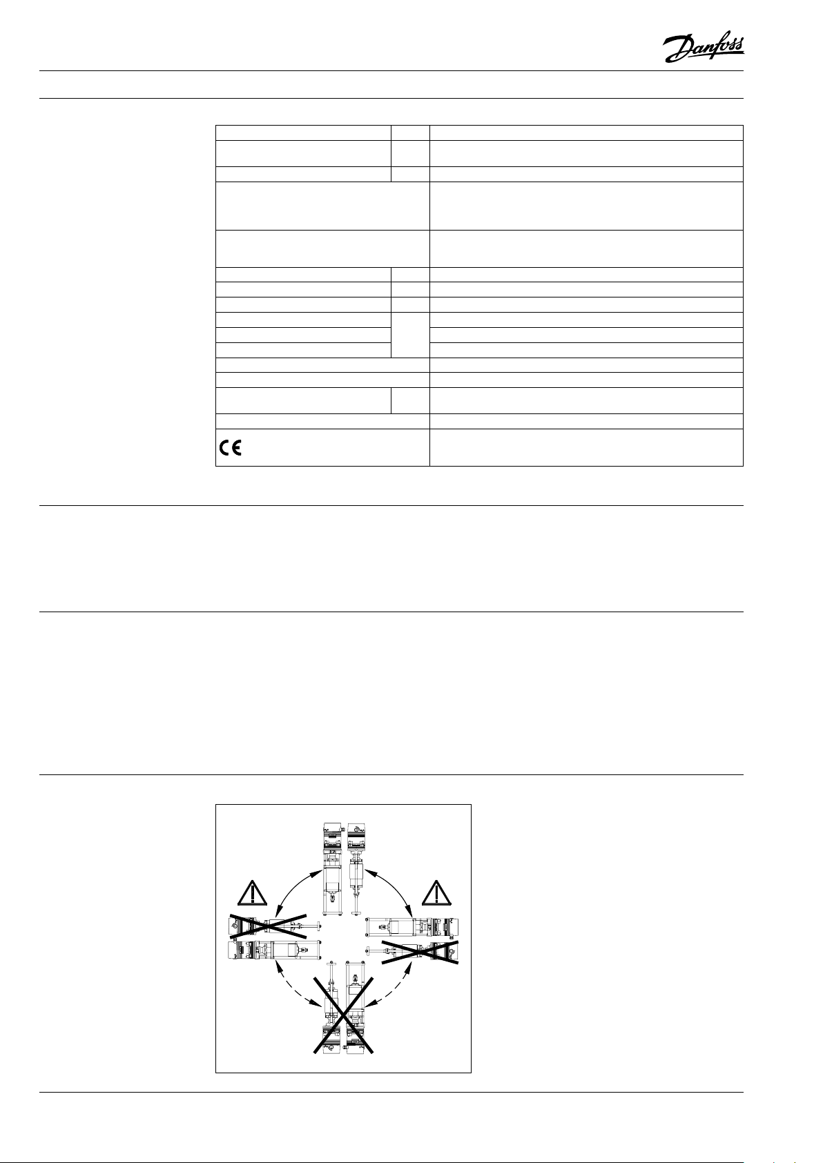
Please check what are allowed installation
positions for the valve in combination. Use
appropriate key (not supplied) to fit the actuator
to the valve body. Allow for necessary clearance
for maintenance purposes. To link valve and
actuator stems use appropriate key (not
supplied). The actuator has position indication
rings which should be pushed together before
el. connection; after self-stroking they indicate
end positions of the stroke.
Electrical
Electrical connections can be accessed by
removing the cover. Four cable entries on
removable gland support are provided for
M 16×1,5 cable glands. Note that in order to
maintain the enclosure IP rating, appropriate
cable glands must be used.
2
VD.IR .M2.02 © Danfoss 05/2015
DEN-SMT/SI
Page 3

Data sheet Electrical actuator AME 855
Design
1. Actuator housing
2. Cross head
3. Coupling piece
4. Union nut
5. Spindle nut
6. Position indicator
7. Protecting tube
8. Distance sleeve
9. Bridge
10. Gear housing
11. Sheeting
12. Knob
13. Hand wheel
14. Viewing panel
15. Guiding sleeve
16. Engine / motor
17. Push-fit PCB for 24 V or 230 V
18. Main board
19. Cover for 24 V or 230 V
20. Cable lead-in M20 × 1.5
21. Cable lead-in M16 × 1,5
22. Safety disk
23. Blank
24. Bolt
25. Hexagon nut M12
26. Type p late
27. Wiring diagram on cover
Wiring
230 VAC version:
Do not touch anything on the
PCB!
Do not remove the cover
before the power supply is fully
switched off.
230V AC
24V AC
Terminal Description
L, N1 Supply voltage
2 Control voltage for downward movement during three-point mode
3 Control voltage for upward movement during three -point mode
R
B1, B2 Binary input / frost protection function
N2
Y Input signal continuous mode
X Output signal continuous mode
20, 21, 22 Terminals path switch unit WE1
23, 24, 25 Terminals path switch unit WE2
Return signal during “manual” mode
• R= 24 V DC max. 35 mA
Zero potential of signals X, Y and R
• When the zero potentials of signals X, Y and R are identical to
the zero potential of the supply voltage it is possible to bridge
terminals N1 and N2 (230V only).
• If you run the actuator in continuous mode at 230 V you will have to
connect N2.
• If you run the actuator in three-point mode at 230 V you will have to
connect N2 if you wish to use X or R at the same time.
DEN-SMT/SI
VD.IR .M2.02 © Danfoss 05/2015
3
Page 4

Data sheet Electrical actuator AME 855
Led signalling/
Actuator operating modes
LED operating mode indicator:
The two-colour (green / red) LED function
indicators are located in the actuator cover. They
indicate different operating modes:
• Normal operation (green LED is permanently
lit, actuator waiting for Y signal command)
• Standard operation (blinking green LED
with short-short rhythm - 0.5s LED is ON and
0.5s LED is off - actuator is following Y signal
command)
• Wire break detection (blinking greed LED
with short-long rhythm - 0.2s LED is ON and
1.5s LED is OFF – input signal Y has dropped
below 1V or 2 mA in operating mode 2-10V or
4-20mA)
• Blockage detection only in modulating
• Remote reset function - continuous signal on
terminals 2,3 (blinking green LED with longshort rhythm – 2.5s LED is ON and 0.5s LED is
OFF – a simultaneous signal at terminals 1 and
3 will result in reset or initialization process
where actuator will adapt its stroke to valve
end positions. Actuator will switch off after 4
unsuccessful attempts)
• Temperature is in normal range (red LED is
off)
• Heating mode (red LED is ON)
• Actuator is overheating (blinking red LED
with short-short rhythm – 0.25s LED is ON
and 0.25s LED is OFF – overheating protection
mode)
control (blinking green LED with long-long
rhythm – 2.5s LED is ON and 2.5s LED is OFF –
actuator is mechanically blocked)
LED Indication type Operating status / error
Constantly lit
Normal operation, ready for operation
The LED is pe rmanently lit, a ctuator waitin g for command signal .
Green LED:
Red LED :
Flashing
0,5s / 0,5s / 0, 5s / 0,5s …
Flashing
0,2s / 1,5s / 0,2 s / 1,5s …
Flashing
2,5s / 2,5s / 2, 5s / 2,5s …
Flashing
1,5s / 0,2s / 1,5s / 0,2 s …
No indication
Constantly lit Heating mode
Flashing
0,25s / 0,2 5s / 0,25s / 0,25s…
Standard Operation
Actuator carries out traverse command.
Wire break detection
Input sig nal has dropped be low 1 V or below 2 mA in op erating
modes
2 … 10 V DC or 4 … 20 .
Blockage detection (continuous mode only)
The linea r actuator is mec hanically bloc ked.
Continuous signal on terminal 2 and 3
A simulta neous control sign al at terminal 2 and 3 wi ll result in an
initiali sing cycle (max. 4 at tempts).
The linea r actuator will au tomatically swi tch off after 4 un successful
attempts.
Temperature in normal range
Actuator overheating
4
VD.IR .M2.02 © Danfoss 05/2015
DEN-SMT/SI
Page 5

Data sheet Electrical actuator AME 855
DIP switch setting
Actuator has a selection of DIP switches under the cover:
• DIP SW 1: Must always be in ON position for stable operation
• DIP SW 2: DIR / INV Y signal(direct or inverse acting mode)
1. DIR position (ON position) – actuator is direct acting to input signal
2. INV position (OFF position) – actuator is inverse acting to input signal
• DIP SW 3: DIR / INV X signal(direct or inverse acting mode)
1. DIR position (ON position) – actuator is giving direct acting output signal
2. INV position (OFF position) – actuator is giving inverse acting output signal
• DIP SW 4: 0-10 V / 2-10V or 0-20mA / 4-20 mA input signal Y
1. 0-10V / 0-20 mA (ON position)
2. 2-10V / 4-20 mA (OFF position)
• DIP SW 5: Without function, do not change switch setting
• DIP SW 6: Auto test function
1. Auto test enabled (ON position)
2. Auto test disabled (OFF position)
• DIP SW 7: Limit position setting
1. Actuator spindle extended (ON position)
2. :Actuator spindle retracted (OFF position)
• DIP SW 8 and 9: Hysteresis settings
1. 0.15 V (SW 8 and 9 in position ON)
2. 0.05 V (SW 8 in ON and SW 9 in OFF position)
3. 0.3 V (SW 8 in OFF and SW 9 in ON position)
4. 0.5 V (SW 8 and 9 in OFF position)
• DIP SW 10: Input signal Y as voltage (V) or current (mA)
1. Drive actuator via current signal from controller (ON position)
2. Drive actuator via voltage signal from controller (OFF position)
DEN-SMT/SI
VD.IR .M2.02 © Danfoss 05/2015
5
Page 6

Data sheet Electrical actuator AME 855
Functions • Internal temperature control:
• Modulating control mode:
System controller pre-sets the position of the
linear actuator whilst inside the linear actuator
the input signal (Y) of the system control
is continuously compared with the output
signal (X) of the linear actuator. In doing so the
output signal depends on the position of the
linear actuator approximated to the valve end
positions.
• 3-point control mode:
The direction of the rotation is set via control
voltage on terminal 2 and 3 on the main PCB.
When the control voltage is applied to terminal
1 the spindle of the actuator will be extending,
when control voltage is applied to terminal 3
the spindle of the actuator will be retracting.
• Frost protection function:
The terminals B1 and B2 on the main PCB
are bridged during the normal operation.
If the electric circuit between B1 and B2 is
interrupted, the linear actuator will store the
current position (3-point mode) and then
automatically move the set end position on DIP
SW 7. The actuator will stay in the selected end
position as long as the circuit between B1 and
B2 is interrupted. After the circuit between B1
and B2 will be restored again, the actuator will
automatically go to the stored position (3-point
mode) or to the desired position by the Y signal
in modulating control mode. Safety thermostat
could be used to control the circuit between B1
and B2 terminals.
• Blockage detection:
If the linear actuator is blocked during
movement, the linear actuator will briefly
move back and then retry to reach the desired
position (will try to remove the blockage). If
this procedure will be unsuccessful after 7
attempts, the linear actuator will turn off in
order to prevent damage of actuator and valve.
A blockage detection is indicated via green
LED indication.
When the temperature inside the actuator
housing exceeds a certain limit (65 °C) the
motor will be turned off. After the temperature
will fall down below limit, actuator will restart
automatically.
When the temperature inside the actuator
housing drops below 15°C the motor will
be switched in the heating mode during
stoppages. Actuator heating will be switched
off automatically when the temperature in
the housing will exceed 22°C. The actuator
heating does not effect on functions of the
actuator. Heating of actuator also prevents the
formation of condensation inside the actuator
and ensures easier movement of the gears
even at temperatures down to -10°C.
Heating mode and motor stoppage are
displayed as a red LED signalization.
• Wire break detection:
Only available in modulating control mode
with 2-10 V or 4-20 mA Y signal. Wire break
detection is displayed as green LED indication.
• Hysteresis setting:
It serves to prevent permanent oscillations
around set hysteresis thresh-hold on DIP SW 8
and 9 when there are minor Y signal changes.
• Auto test function:
If a valve does not operate for a while the cone
of the valve might get stuck. Auto test function
acts a prevent measure for that to happen.
Linear actuator will after 10 days of no activity
move to the end position of the valve set on
DIP SW 7 and then move to the previous initial
position.
• Auto pause function:
This function is used to prevent over-oscillating
behaviour of the actuator in response to the
Y control signal. If there are more than 20
direction varying Y signal commands per
minute, actuator will go in a pause for 3s and
then continue to follow Y signal.
6
VD.IR .M2.02 © Danfoss 05/2015
DEN-SMT/SI
Page 7

Data sheet Electrical actuator AME 855
Manual operation Actuator AME 855 can be manually operated
when the manual operation clutch is in upper
position. Actuator has default factory setting
in automatic mode (manual operation clutch in
down position). If the actuator is under supply
①
Auto
④
voltage when in manual operation mode, R
terminal will give position output signal. After
the manual operation, the manual operation
clutch must be put in down position for the
automatic mode to be applied again.
③
②
Click
Manual
④
Dimensions
Ø120
~770
200
Stroke113
DEN-SMT/SI
VD.IR .M2.02 © Danfoss 05/2015
Ø5 7,1
120
170
M14
+0,1
15
7
Page 8

Data sheet Electrical actuator AME 855
Actuator - valve
combination
min. 200
1
H
Typ e DN
200 600 276 10 68
VF3
250 730 316 1080
300 850 378 1113
L H H
mm
1
H
L
8
VD.IR .M2 .02
Produce d by Danfoss A/S © 05/2015
 Loading...