

Data sheet
Actuators for modulating control
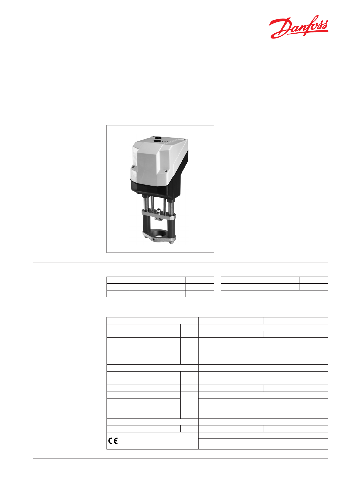
AME 85, AME 86
Description
Ordering
Actuator
Typ e Power supply Speed Code No.
AME 85 24 V~ 8 s/mm 082G1452
AME 86 24 V~ 3 s/mm 082G1462
The actuators AME 85 and AME 86 are used with
VFM 2 (DN 150-250), VFS 2 (DN 65-100),
VF2/3 (DN 125, 150) and AFQM (DN150-250) valves.
Features:
• “Self stroking” function
• Load related “Switch o“ function that
prevents overloading
• Manual operation
• Diagnostic LED
Main data:
• Nominal voltage:
- 24 VAC , 50 Hz/60 Hz
• Control input signal:
- 0(4)-20 mA
- 0(2)-10 V
• Force: 5000 N
• Stroke: 40 mm
• Speed: 8 s/mm (AME 85), 3 s/mm (AME 86)
• Max. medium temperature: 200 °C
• Manual operation
Accessories
Typ e Code No.
Stem heater 065Z7021
Technical data
DEN-SMT/SI
Typ e AME 85 AME 86
Power supply V 24 AC +10 to –15%
Power consumption VA 12. 5 25
Frequency Hz 50 / 60
Control input Y
Output signal X V 0 to 10 (2 to 10)
EMC IEC 801/2 - 5
Closing force N 5000
Max. stroke mm 40
Speed s/mm 8 3
Max. medium temperature
Ambient temperature 0 to 55
Storage and transport temperature –40 to +70
Protection Class
Grade of enclosure IP 54
Weight kg 9.8 10.0
- marking in accordance with the standards
VD.AB.R6.02 © Danfoss 09/2015
V 0 to 10 (2 to 10) Ri = 200 Ω,
mA 0 to 20 (4 to 20) Ri = 500 Ω
200
°C
III (24 V)
Low Voltage Directive 73/23/EEC and 93/68/EEC , EN 60730/2/14
EMC Directive 89/336/EEC, 92/31/EEC, 93/68/EEC, EN 50081-1 and
EN 50 082-1
1
Data sheet Actuators for modulating control AME 85, AME 86
Installation
Disposal
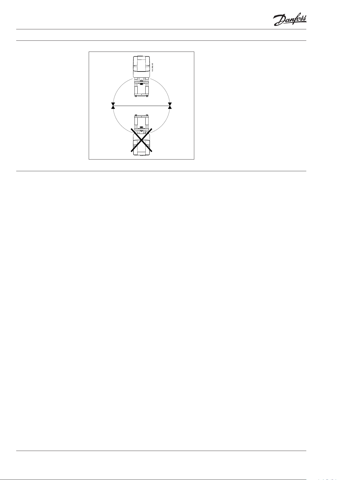
Mechanical
The actuator should be mounted with the valve
stem in either horizontal position or pointing
upwards. Use the 57 mm castellated nut
(supplied) to t the actuator to the valve body.
While the actuator is being tted, a 8 mm Allen
key can be used to tighten the pinch screw in the
valve body ring to stop the valve turning.
Allow for necessary clearance for maintenance
purposes.
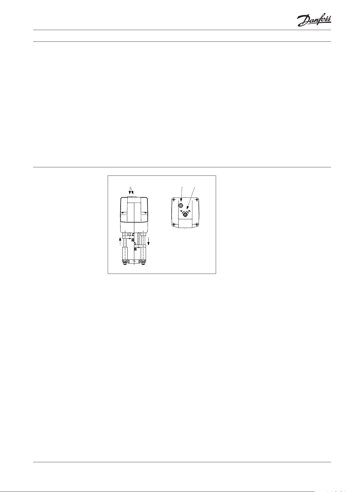
Electrical
Electrical connections can be accessed by
removing the cover. Two M16 x 1.5 cable entries
are provided. Both entries are provided with a
rubber grommet for use with exible cable. Note
that in order to maintain the enclosure IP rating,
appropriate cable glands must be used.
The actuator must be dismantled and the
elements sorted into various material groups
before disposal.
2
VD.AB.R6.02 © Danfoss 09/2015
DEN-SMT/SI

Data sheet Actuators for modulating control AME 85, AME 86
DIP switch setting
The actuator has a function selection DIP switch
under the removable cover. In particular, if SW6 is
set to ON, the actuator will perform as
3-point actuator.
The switch provides the following functions:
• SW1: U/I - Input signal type selector:
If set to OFF position, voltage input is selected. If
set to ON position, current input is selected.
• SW2: 0/2 - Input signal range selector:
If set to OFF position, the input signal is in the
range from 2 V to 10 V (voltage input)
or from 4 mA to 20 mA (current input). If set to
ON position, the input signal is in the range from
0 V to 10 V (voltage input) or from 0 mA to 20 mA
(current input).
• SW3: D/I - Direct or inverse acting selector:
If set to OFF position, the actuator is direct acting
(stem lowers as voltage increases). If actuator is
set to ON position the actuator is inverse acting
(stem raises as voltage increases).
• SW4: —/Seq - Normal or sequential mode
selector:
If set to OFF position, the actuator is working
in range 0(2)..10V or 0(4)..20mA. If set to ON
position, the actuator is working in sequential
range; 0(2)..5 (6)V or (0(4)..10 (12)mA) or (5(6)..10V)
or (10(12)..20mA).
• SW6: Prop./3-pnt - Modulating or 3-point
mode selector:
If set to OFF position, the actuator is working
normally according to control signal. If set to
ON position, the actuator is working as 3-point
actuator.
• SW7: LOG/LIN - Equal percentage or linear
ow through valve selector1:
If set to OFF position, the ow through valve is
equal percentage. If set to ON position, the he
ow through valve is linear according to control
signal.
• SW8: 100% KVS/Reduced KVS - Flow reduction
through valve selector1:
If set to OFF position, the ow through valve is
not reduced. If set to ON position, the he ow
through valve reduced by half of increment
standard KVS values (exsample: valve with KVS 16
and SW8 set to ON – maximum ow through the
velve is KVS13 (meiidle between standard KVS 16
and KVS 10).
1
NOTE: To be used only in comb ination with valves with equa l
percentage characteristic.
• SW9: Reset:
Changing this switch position will cause the
actuator to go through a self stroking cycle.
DEN-SMT/SI
• SW5: 0..5V/5...10V - Input signal range in
sequential mode:
If set to OFF position, the actuator is working in
sequential range 0(2)..5 (6)V or 0(4)..10 (12)mA.
If set to ON position, the actuator is working in
sequential range; 5(6)..10V or 10(12)..20mA.
VD.AB.R6.02 © Danfoss 09/2015
3

Data sheet Actuators for modulating control AME 85, AME 86
Wiring
24 Vac only.
Wiring length
0 - 50 m 0.75 mm
> 50 m 1.5 mm
Recommended
square of the wiring
2
2
Automatic self stroking feature
When power is rst applied, the actuator will
automatically adjust to the length of the valve
stroke. Subsequently, the self stroking feature
can be re-initialised by changing position of SW9.
DIP 6 = OFF
Diagnostic LED
The red diagnostic LED is located on the pcb
under the cover. It provides indication of three
operational states:
• Actuator Healthy (Permanently ON),
• Self Stroking (Flashes once per second),
• Error (Flashes 3 times per second - seek
technical assistance).
SN 0 V Neutral
SP 24 VAC Power supply
Y
1
24 VAC Input
3
X 0(2) -10 V Output
0(2)-10 VAC
0(4) -20 mA
Input
Controller with relay output
Controller with triacs output
DIP 6 = ON
DIP 6 = ON
SN
SP
1
24 VAC Input
3
X 0(2 )-10 V DC Output
SN 24 V Power supply
SP 0 V Neutral
1
24 VAC Input
0 V
24 VAC
Neutral
Power supply
3
4
VD.AB.R6.02 © Danfoss 09/2015
DEN-SMT/SI
Data sheet Actuators for modulating control AME 85, AME 86
Commissioning Commissioning / testing feature
Complete the mechanical and electrical
installation and perform the necessary checks
and tests:
The actuator can be driven to the fully open or
closed positions (depending on valve type) by
connecting SN to terminals 1 or 3.
• Isolate control medium. (e.g. self stroking
in a steam application without suitable
mechanical isolation could cause a hazard).
• Apply the power. Note that the actuator will
now perform the self stroking function.
• Apply the appropriate control signal and
check the valve stem direction is correct for
the application.
• Ensure that the actuator drives the valve over
its full stroke, by applying the appropriate
control signal. This action will set the valve
stroke length.
The unit is now fully commissioned.
Manual override
(1)Remove grommets (2)Push (3)Turn
The manual override is applied by rotating the
8 mm Allen key (not supplied) to the required
position. Observe the direction of rotation
symbol.
• Disconnect power
• Remove grommets and push the button
• Adjust valve position using an 8 mm Allen key
• Set valve to closed position
• Restore power
Note:
Actuator will restore position required by
Y signal.
DEN-SMT/SI
VD.AB.R6.02 © Danfoss 09/2015
5

Data sheet Actuators for modulating control AME 85, AME 86
Dimensions
6
VD.AB.R6.02 © Danfoss 09/2015
DEN-SMT/SI

Data sheet Actuators for modulating control AME 85, AME 86
Actuator - valve
combinations
AME 85/86 + VFS 2 (DN 65 - 100)
AME 85/86 + VF 3 (DN 125 - 150)
AME 85/86 + VFM 2 (DN 150-250)AME 85/86 + VF 2 (DN 125 - 150)
DEN-SMT/SI
VD.AB.R6.02 © Danfoss 09/2015
AME 85/86 + AFQM (DN 150 - 250)
7

Data sheet Actuators for modulating control AME 85, AME 86
8
VD.AB.R6.02 Produce d by Danfoss A/S © 09/2015
 Loading...