

Daikin RXYSQ4M7V3B, RXYSQ5M7V3B, RXYSQ6M7V3B Installation Manual

INSTALLATION MANUAL
System air conditioner
RXYSQ4M7V3B
RXYSQ5M7V3B
RXYSQ6M7V3B
D2D2
L1
L2
B1
B2
D2D2
L1
L2
3
1
1
1
4
D2D2
D2
CC
L2
L2
AA
D2D2
D2
CC
L2
L2
AA
2
2
3
500
≥1
1
≥1000
≥1000
≥1000
≥1500
6
4
≥1500
≥1500
5
3
2
(mm)
2 3
B2
B2
EE
L1
L1
HH
B1B1B1
D1D1D1
B2B2B2
EE
L1
L1
HH
B1
B1
D1D1D1
L2>H
L2<H
L2>H
L2<H
L2>H
L2<H
L2>H
L2<H
≥100
≥100
≥100
≥100
≥150 ≥150
≥100
≥100
L1≤H
H<L1
L2≤H
H<L2
L1≤H
H<L1
L2≤H
H<L2
≥250
≥100
≥200
≥300≥200
≥200 ≥1000
≥300
≥300
≥250
≥300
≥300 ≤500
≥250
≥300
≤500
≤500
≤500
ABB
3
1
2
3
1
2
CC
≥100
≤500 ≥1000
≤500
≥150
≥500
≥500
≥500
≥500
≥750
≥1000
L1≤H
≥1000
L2≤H
≥1000
≥1000
≥1000
≥1000
≥1500
≥1000
≥1250
L1≤H
≥1500
L2≤H
≥1000
≥1000
≥1000
≤500
≥1000
≤500
≥1000
≥1000
≥1000
≤500 ≥1000
0<L1≤1/2 H
1
/2 H<L1≤H
0<L2≤1/2 H
1
/2 H<L2≤H
0<L2≤1/2 H
1
/2 H<L2≤H
0<L1≤1/2 H
1
/2 H<L1≤H
0<L2≤1/2 H
1
/2 H<L2≤H
3
1
3
3
1+2
3
4
5
321
78
B
9
44
5 611
10
A
C
7
D
5
9
8
10
6
1
4
7
12
1111
3
2
6
56
13
21
7
V
V
V
V
V
3
12
2
11
TO IN/D
UNIT
F1 F2
ON
OFF
O
U
T
1234
I
N
DS1
8
1
9
11
13
230
4
1
16 V
8
LN
10
F1 F2 F1 F2
F1 F2
1
11
12
2
1
9
3
230
16
16
16
4 4
4
55 5
8
10
7
A1P
1
A B C
A B C
12
13
1
F2F1 F2F1
ON
OFF
1
O
U
T
1234
I
N
2
DS1
F2F1
6
12
3
5
4
A B C
TO OUT/D UNIT
A1P
TO IN/D UNIT
2
ABCF1 F1F2 F2
C/H SELECTOR
2
C
}
3
2
A
}
3
13
2
3
14
B
}
123454
F2F1 F2F1
14
4
5
10
15
A
F1 F2 F1 F2 F1 F2
F1 F2 F1 F2 F1 F2
F1 F2 F1 F2 F1 F2
B
15
13
14
E
2
9
C
D
E
1
2
3
E
E
E
1
1
1
3
2
4 5
25
24 35
4
3
15
.
01
02
03
04
05
06
07
08
09
ATITIKTIES-DEKLARACIJA
ATBILSTĪBAS-DEKLARĀCIJA
VYHLÁSENIE-ZHODY
CE -
CE -
CE -
CE - UYUMLULUK-BİLDİRİSİ
ZJAVA O SKLADNOSTI
VASTAVUSDEKLARATSIOON
ДЕКЛАРАЦИЯ-ЗА-СЪОТВЕТСТВИЕ
CE - I
CE -
CE -
z vso odgovornostjo izjavlja, da so modeli klimatskih naprav, na katere se izjava nanaša:
kinnitab oma täielikul vastutusel, et käesoleva deklaratsiooni alla kuuluvad kliimaseadmete mudelid:
10
11
12
13
14
15
16
17
18
19
20
21
22
23
24
25
01
02
03
04
05
06
07
08
09
10
11
12
13
14
15
16
17
18
19
20
21
22
23
24
25
01
02
03
04
05
06
07
08
09
10
11
12
13
14
15
16
17
18
19
20
21
22
23
24
25
01
02
03
04
05
06
07
08
09
10
11
12
13
14
15
16
17
18
19
20
21
22
23
24
25
.
.
.
.
*
.
Direktive z vsemi spremembami.
Direktiivid koos muudatustega.
Директиви, с техните изменения.
Direktyvose su papildymais.
Direktīvās un to papildinājumos.
Smernice, v platnom znení.
Değiştirilmiş halleriyle Yönetmelikler.
Direktiver, med senere ændringer.
Direktiv, med företagna ändringar.
Direktiver, med foretatte endringer.
Direktiivejä, sellaisina kuin ne ovat muutettuina.
v platném znění.
Smjernice, kako je izmijenjeno.
irányelv(ek) és módosításaik rendelkezéseit.
z późniejszymi poprawkami.
Directivelor, cu amendamentele respective.
декларира на своя отговорност, че моделите климатична инсталация, за които се отнася тази декларация:
visiška savo atsakomybe skelbia, kad oro kondicionavimo prietaisų modeliai, kuriems yra taikoma ši deklaracija:
ar pilnu atbildību apliecina, ka tālāk uzskaitīto modeĮu gaisa kondicionētāji, uz kuriem attiecas šī deklarācija:
vyhlasuje na vlastnú zodpovednosť, že tieto klimatizačné modely, na ktoré sa vzťahuje toto vyhlásenie:
tamamen kendi sorumluluğunda olmak üzere bu bildirinin ilgili olduğu klima modellerinin aşağıdaki gibi olduğunu beyan eder:
megfelelnek az alábbi szabvány(ok)nak vagy egyéb irányadó dokumentum(ok)nak, ha azokat előírás szerint használják:
spełniają wymogi następujących norm i innych dokumentów normalizacyjnych, pod warunkiem że używane są zgodnie z naszymi
instrukcjami:
sunt în conformitate cu următorul (următoarele) standard(e) sau alt(e) document(e) normativ(e), cu condiţia ca acestea să fie utilizate în
conformitate cu instrucţiunile noastre
skladni z naslednjimi standardi in drugimi normativi, pod pogojem, da se uporabljajo v skladu z našimi navodili:
on vastavuses järgmis(t)e standardi(te)ga või teiste normatiivsete dokumentidega, kui neid kasutatakse vastavalt meie juhenditele:
съответстват на следните стандарти или други нормативни документи, при условие, че се използват съгласно нашите
инструкции:
atitinka žemiau nurodytus standartus ir (arba) kitus norminius dokumentus su sąlyga, kad yra naudojami pagal mūsų nurodymus:
tad, ja lietoti atbilstoši ražotāja norādījumiem, atbilst sekojošiem standartiem un citiem normatīviem dokumentiem:
sú v zhode s nasledovnou(ými) normou(ami) alebo iným(i) normatívnym(i) dokumentom(ami), za predpokladu, že sa používajú v súlade
s našim návodom:
ürünün, talimatlarımıza göre kullanılması koşuluyla aşağıdaki standartlar ve norm belirten belgelerle uyumludur:
. 07
*
*
.
.
.
.
.
.
.
i
.
съгласно
TNO
0305020101
în conformitate
TNO
järgi vastavalt
certifikatom
TNO
pagal
v skladu s
şi apreciate pozitiv de
TNO
DAIKIN.TCF.022
in odobreno s strani
TNO
и оценено положително от
ja heaks kiidetud
ir patvirtinta
DAIKIN.TCF.022
DAIKIN.TCF.022
DAIKIN.TCF.022
tarafından olumlu olarak
TNO
podľa
göre
TNO
sertifikasına
a kladne posúdené
pozitīvajam lēmumam ko apliecina
TNO
0305020101
, atbilstoši
DAIKIN.TCF.022
DAIKIN.TCF.022
DAIKIN.TCF.022
0305020101
0305020101
0305020101
0305020101
Certificatul
cu
conform celor stabilite în Dosarul tehnic de construcţie
kot je določeno v tehnični mapi
nagu on näidatud tehnilises dokumentatsioonis
sertifikaadile
както е заложено в Акта за техническа конструкция
Сертификат
kaip nurodyta Techninėje konstrukcijos byloje
pažymėjimą
Notă *
18
19 Opomba *
20 Märkus
21 Забележка *
22 Pastaba *
Teknik Yapı Dosyasında belirtildiği gibi ve
0305020101
0305020101
kā noteikts tehniskajā dokumentācijā
değerlendirilmiştir.
sertifikāts
ako je to stanovené v Súbore technickej konštrukcie
Certifikátu
DAIKIN.TCF.022
Not
23 Piezīmes *
24 Poznámka *
25
.
.
*
.
.
.
.
.
*
Zandvoordestraat 300, B-8400 Oostende, Belgium
IZJAVA-O-USKLAĐENOSTI
DEKLARACJA-ZGODNOŚCI
DECLARAŢIE-DE-CONFORMITATE
CE - MEGFELELŐSÉGI-NYILATKOZAT
CE -
CE -
CE -
PROHLÁŠENÍ-O-SHODĚ
CE - ERKLÆRING OM-SAMSVAR
CE - ILMOITUS-YHDENMUKAISUUDESTA
CE -
prohlašuje ve své plné odpovědnosti, že modely klimatizace, k nimž se toto prohlášení vztahuje:
izjavljuje pod isključivo vlastitom odgovornošću da su modeli klima uređaja na koje se ova izjava odnosi:
teljes felelőssége tudatában kijelenti, hogy a klímaberendezés modellek, melyekre e nyilatkozat vonatkozik:
deklaruje na własną i wyłączną odpowiedzialność, że modele klimatyzatorów, których dotyczy niniejsza deklaracja:
declară pe proprie răspundere că aparatele de aer condiţionat la care se referă această declaraţie:
erklærer under eneansvar, at klimaanlægmodellerne, som denne deklaration vedrører:
deklarerar i egenskap av huvudansvarig, att luftkonditioneringsmodellerna som berörs av denna deklaration innebär att:
erklærer et fullstendig ansvar for at de luftkondisjoneringsmodeller som berøres av denne deklarasjon innebærer at:
ilmoittaa yksinomaan omalla vastuullaan, että tämän ilmoituksen tarkoittamat ilmastointilaitteiden mallit:
CE - DECLARAÇÃO-DE-CONFORMIDADE СЕ - ЗАЯВЛЕНИЕ-О-СООТВЕТСТВИИ
CE - OPFYLDELSESERKLÆRING
CE - FÖRSÄKRAN-OM-ÖVERENSTÄMMELSE
CE - ¢H§ø™H ™YMMOPºø™H™
CE - DECLARACION-DE-CONFORMIDAD
CE - DICHIARAZIONE-DI-CONFORMITA
estão em conformidade com a(s) seguinte(s) norma(s) ou outro(s) documento(s) normativo(s), desde que estes sejam utilizados de
acordo com as nossas instruções:
соответствуют следующим стандартам или другим нормативным документам, при условии их использования согласно нашим
инструкциям:
overholder følgende standard(er) eller andet/andre retningsgivende dokument(er), forudsat at disse anvendes i henhold til vore
instrukser:
respektive utrustning är utförd i överensstämmelse med och följer följande standard(er) eller andra normgivande dokument, under
förutsättning att användning sker i överensstämmelse med våra instruktioner:
respektive utstyr er i overensstemmelse med følgende standard(er) eller andre normgivende dokument(er), under forutssetning av at
disse brukes i henhold til våre instrukser:
vastaavat seuraavien standardien ja muiden ohjeellisten dokumenttien vaatimuksia edellyttäen, että niitä käytetään ohjeidemme
mukaisesti:
za předpokladu, že jsou využívány v souladu s našimi pokyny, odpovídají následujícím normám nebo normativním dokumentům:
u skladu sa slijedećim standardom(ima) ili drugim normativnim dokumentom(ima), uz uvjet da se oni koriste u skladu s našim uputama:
Directives, as amended.
Direktiven, gemäß Änderung.
Directives, telles que modifiées.
Richtlijnen, zoals geamendeerd.
Directivas, según lo enmendado.
Direttive, come da modifica.
√‰ËÁÈÒv, fiˆ˜ ¤¯Ô˘Ó ÙÚÔÔÔÈËı›.
Directivas, conforme alteração em.
Директив со всеми поправками.
Low Voltage 73/23/EEC
Machinery Safety 98/37/EEC
Electromagnetic Compatibility 89/336/EEC *
ob upoštevanju določb:
vastavalt nõuetele:
следвайки клаузите на:
laikantis nuostatų, pateikiamų:
ievērojot prasības, kas noteiktas:
održiavajúc ustanovenia:
bunun koşullarına uygun olarak:
under iagttagelse af bestemmelserne i:
enligt villkoren i:
gitt i henhold til bestemmelsene i:
noudattaen määräyksiä:
za dodržení ustanovení předpisu:
prema odredbama:
követi a(z):
zgodnie z postanowieniami Dyrektyw:
în urma prevederilor:
TNO
vilket också
ifølge
TNO
TNO
i henhold
som positivt intygas av
TNO
og gjennom positiv bedømmelse av
DAIKIN.TCF.022
и в соответствии с положительным решением
og positivt vurderet af
DAIKIN.TCF.022
DAIKIN.TCF.022
DAIKIN.TCF.022
0305020101
0305020101
Certifikat
Свидетельству
Certifikat 0305020101
как указано в Досье технического толкования
som anført i den Tekniske Konstruktionsfil
utrustningen är utförd i enlighet med den Tekniska Konstruktionsfilen
som det fremkommer i den Tekniske Konstruksjonsfilen
Sertifikat 0305020101
til
согласно
framgår av
09 Примечание *
10 Bemærk *
11 Information *
12 Merk *
conformément
TNO
overeenkomstig
according to
TNO
TNO
positiv ausgezeichnet gemäß
TNO
et jugé positivement par
en in orde bevonden door
and judged positively by
aufgeführt und von
DAIKIN.TCF.022
DAIKIN.TCF.022
DAIKIN.TCF.022
DAIKIN.TCF.022
prema
TNO
v souladu
TNO
TNO
igazolta a megfelelést
on hyväksynyt
TNO
TNO
, pozytywną opinią
i pozitivno ocijenjeno od strane
a pozitivně zjištěno
ja jotka
DAIKIN.TCF.022
DAIKIN.TCF.022
DAIKIN.TCF.022
DAIKIN.TCF.022
mukaisesti.
0305020101
jotka on esitetty Teknisessä Asiakirjassa
Sertifikaatin
jak bylo uvedeno v souboru technické konstrukce
13 Huom *
14 Poznámka *
según
TNO
szerint.
műszaki konstrukciós dokumentáció alapján, a(z)
tanúsítvány
0305020101
osvědčením
s
kako je izloženo u Datoteci o tehničkoj konstrukciji
15 Napomena *
Û‡Ìʈӷ Ì ÙÔ
TNO
0305020101
0305020101
DAIKIN.TCF.022
0305020101
Świadectwem
Certifikatu
a(z)
zgodnie z archiwalną dokumentacją konstrukcyjną
a(z)
16 Megjegyzés *
17 Uwaga *
Katsuyuki Sawai
de acordo com o
TNO
secondo
TNO
Î·È ÎÚ›ÓÂÙ·È ıÂÙÈο ·fi ÙÔ
y juzgado positivamente por
DAIKIN.TCF.022
DAIKIN.TCF.022
e giudicato positivamente da
e com o parecer positivo de
DAIKIN.TCF.022
DAIKIN.TCF.022
Assistant Director Quality Assurance
Ostend, 1st of June 2004
declares under its sole responsibility that the air conditioning models to which this declar ation relates:
erklärt auf seine alleinige Verantwortung daß die Modelle der Klimageräte für die diese Erklärung bestimmt ist:
déclare sous sa seule responsabilité que les appareils d'air conditionné visés par la présente déclar ation:
verklaart hierbij op eigen exclusieve verantwoordelijkheid dat de airconditioning units waarop deze verklaring betrekking heeft:
declara baja su única responsabilidad que los modelos de aire acondicionado a los cuales hace referencia la declaración:
CE - DECLARATION-OF-CONFORMITY
CE - KONFORMITÄTSERKLÄRUNG
CE - DECLARATION-DE-CONFORMITE
CE - CONFORMITEITSVERKLARING
Daikin Europe N.V.
dichiara sotto sua responsabilità che i condizionatori modello a cui è riferita questa dichiarazione:
0305020101
0305020101
0305020101
Certificate
the
wie in der Technischen Konstruktionsakte
Zertifikat
02 Hinweis *
Certificat
tel que stipulé dans le Fichier de Construction Technique
zoals vermeld in het Technisch Constructiedossier
Certificaat 0305020101
au
03 Remarque *
04 Bemerk *
tal como se expone en el Archivo de Construcción Técnica
05 Nota
as set out in the Technical Construction File
‰ЛПТУВИ МВ ·ФОПВИЫЩИО‹ ЩЛ˜ В˘ı‡УЛ fiЩИ Щ· МФУЩ¤П· ЩˆУ ОПИМ·ЩИЫЩИОТУ Ы˘ЫОВ˘ТУ ЫЩ· ФФ›· ·У·К¤ЪВЩ·И Л ·ЪФ‡Ы· ‰‹ПˆЫЛ:
заявляет, исключительно под свою ответственность, что модели кондиционеров воздуха, к которым относится настоящее заявление:
are in conformity with the following standard(s) or other normative document(s), provided that these are used in accordance with our
instructions:
der/den folgenden Norm(en) oder einem anderen Normdokument oder -dokumenten entspricht/entsprechen, unter der Voraussetzung,
daß sie gemäß unseren Anweisungen eingesetzt werden:
declara sob sua exclusiva responsabilidade que os modelos de ar condicionado a que esta declaração se refere:
RXYSQ4M7V3B, RXYSQ5M7V3B, RXYSQ6M7V3B
sont conformes à la/aux norme(s) ou autre(s) document(s) nor matif(s), pour autant qu'ils soient utilisés conformément à nos instructions:
conform de volgende norm(en) of één of meer andere bindende documenten zijn, op voorwaarde dat ze worden gebruikt overeenkomstig
onze instructies:
están en conformidad con la(s) siguiente(s) norma(s) u otro(s) documento(s) nor mativo(s), siempre que sean utilizados de acuerdo con
nuestras instrucciones:
sono conformi al(i) seguente(i) standard(s) o altro(i) documento(i) a carattere normativo, a patto che vengano usati in conformità alle
nostre istruzioni:
В›У·И Ы‡МКˆУ· МВ ЩФ(·) ·ОfiПФ˘ıФ(·) ЪfiЩ˘Ф(·) ‹ ¿ППФ ¤ББЪ·КФ(·) О·УФУИЫМТУ, ˘fi ЩЛУ ЪФ¸fiıВЫЛ fiЩИ ¯ЪЛЫИМФФИФ‡УЩ·И
Û‡Ìʈӷ Ì ÙȘ Ô‰ËÁ›Â˜ Ì·˜:
following the provisions of:
gemäß den Vorschriften der:
conformément aux stipulations des:
overeenkomstig de bepalingen van:
EN60335-2-40,
siguiendo las disposiciones de:
secondo le prescrizioni per:
Ì ًÚËÛË Ùˆv ‰È·Ù¿Íˆv Ùˆv:
de acordo com o previsto em:
в соответствии с положениями:
01 Note *
0305020101
0305020101
Certificado 0305020101
Certificato
il
delineato nel File Tecnico di Costruzione
fiˆ˜ ÚÔÛ‰ÈÔÚ›˙ÂÙ·È ÛÙÔ ∞Ú¯Â›Ô ∆¯ÓÈ΋˜ ∫·Ù·Û΢‹˜
¶ИЫЩФФИЛЩИОfi
el
™ËÌ›ˆÛË
06 Nota *
0305020101
tal como estabelecido no Ficheiro Técnico de Construção
Certificado
08 Nota
3PW14488-4D
RXYSQ4M7V3B
RXYSQ5M7V3B
RXYSQ6M7V3B
VRVII-S system air conditioner
Installation manual
CONTENTS Page
1. Safety considerations.................................................................1
2. Introduction ................................................................................ 2
2.1. Combination..................................................................................... 2
2.2. Standard supplied accessories........................................................ 2
2.3. Optional accessories ....................................................................... 2
2.4. Technical and electrical specifications............................................. 2
3. Before installation ......................................................................3
3.1. Precautions for R-410A ................................................................... 3
3.2. Installation........................................................................................ 3
3.3. Handling........................................................................................... 3
4. Selecting installation site............................................................3
5. Precautions on installation.........................................................4
5.1. Installation method for prevention of falling over.............................. 4
5.2. Method for removing transport fittings .............................................4
6. Installation servicing space........................................................4
7. Refrigerant pipe size and allowable pipe length.........................5
7.1. Selection of piping material.............................................................. 5
8. Precautions on refrigerant piping...............................................6
8.1. Cautions for brazing......................................................................... 6
8.2. Cautions for flare connection ........................................................... 6
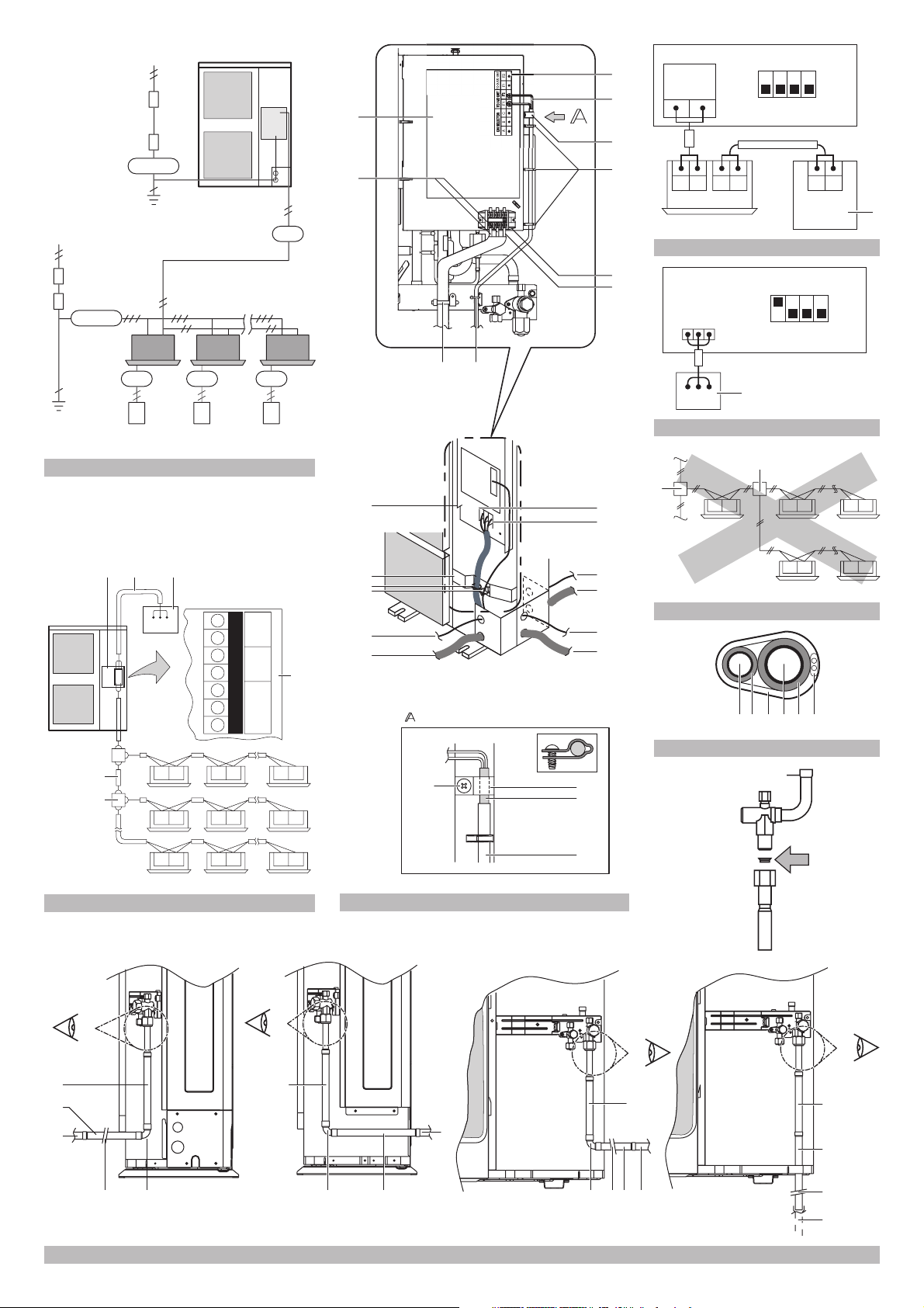
9. Refrigerant piping.......................................................................7
9.1. Preventing foreign objects from entering ......................................... 7
9.2. Cautions for handling stop valve...................................................... 7
9.3. How to use the shut-off valve........................................................... 7
9.4. Cautions for handling the valve cover.............................................. 8
9.5. Cautions for handling service port ...................................................8
9.6. Precautions when connecting fi eld piping and regarding insulation . 8
9.7. Leak test and vacuum drying......................................................... 10
9.8. Additional refrigerant charge.......................................................... 10
10. Electrical wiring work ...............................................................11
10.1. Internal wiring – Parts table........................................................... 11
10.2. Precautions on electrical wiring work ............................................11
10.3. Connection example of total system wiring ................................... 11
10.4. Connecting power wire and transmission wires............................. 12
10.5. Power circuit and cable requirements............................................ 12
11. Before operation ......................................................................14
11.1. Service precautions....................................................................... 14
11.2. Checks before initial start-up ......................................................... 14
11.3. Field setting ................................................................................... 14
11.4. Test operation ................................................................................ 16
11.5. Checks in normal operation........................................................... 17
13. Caution for refrigerant leaks.....................................................18
13.1. Introduction.................................................................................... 18
13.2. Maximum concentration level ........................................................ 18
13.3. Procedure for checking maximum concentration........................... 18
14. Disposal requirements ............................................................. 18
READ THESE INSTRUCTIONS CAREFULLY BEFORE
INSTALLATION. KEEP THIS MANUAL IN A HANDY
PLACE FOR FUTURE REFERENCE.
IMPROPER INSTALLATION OR ATTACHMENT OF
EQUIPMENT OR ACCESSORIES COULD RESULT IN
ELECTRIC SHOCK, SHORT-CIRCUIT, LEAKS, FIRE OR
OTHER DAMAGE TO THE EQUIPMENT. BE SURE ONLY
TO USE ACCESSORIES MADE BY DAIKIN WHICH ARE
SPECIFICALLY DESIGNED FOR USE WITH THE
EQUIPMENT AND HAVE THEM INSTALLED BY A
PROFESSIONAL.
DAIKIN EQUIPMENT IS DESIGNED FOR COMFORT
APPLICATIONS. FOR USE IN OTHER APPLICATIONS,
PLEASE CONTACT YOUR LOCAL DAIKIN DEALER.
IF UNSURE OF INSTALLATION PROCEDURES OR USE,
ALWAYS CONTACT YOUR DEALER FOR ADVICE AND
INFORMATION.
1. SAFETY CONSIDERATIONS
The precautions listed here are divided into the following two types.
Both cover very important topics, so be sure to follow them carefully.
WARNING
If the warning is not observed, it may cause serious casualties.
CAUTION
If the caution is not observed, it may cause injury or damage to the
equipment.
WARNING
■ Ask your dealer or qualified personnel to carry out
installation work. Do not install the machine by
yourself.
Improper installation may result in water leakage,
electric shocks or fire.
■ Perform installation work in accordance with this
installation manual.
Improper installation may lead to water leakage,
electric shocks or fire.
■ When a unit is installed in a small room, it is necessary
to take measures so that the leaked refrigerant amount
does not exceed the limit even if it leaks. As for the
measures to prevent the leak from not exceeding the
limit, please consult with your distributor.
If the leaked amount exceeds the limit, it may cause
an oxygen deficiency accident.
■ Be sure to use only the specified accessories and
parts for installation work.
Failure to use the specified parts may result in water
leakage, electric shocks, fire, or the unit falling.
■ Install the air conditioner on a foundation that can
withstand its weight.
Insufficient strength may result in the fall of equipment
and causing injury.
■ Carry out the specified installation work in consideration
of strong winds, typhoons, or earthquakes.
Improper installation work may result in accidents due
to fall of equipment.
■ Make certain that all electrical work is carried out by
qualified personnel according to the local laws and
regulations and this installation manual, using a
separate circuit.
Insufficient capacity of the power supply circuit or
improper electrical construction may lead to electric
shocks or fire.
■ Make sure that all wiring is secure, using the specified
wires and ensuring that external forces do not act on
the terminal connections or wires.
Incomplete connection or fixing may cause a fire.
■ When wiring between the indoor and outdoor units,
and wiring the power supply, form the wires so that
the frontside panel can be securely fastened.
If the frontside panel is not in place, overheat of the
terminals, electric shocks or a fire may be caused.
■ If refrigerant gas leaks during installation work,
ventilate the area immediately.
To xic gas may be produced if refrigerant gas comes
into contact with fire.
■ After completing the installation work, check to make
sure that there is no leakage of refrigerant gas.
To xic gas may be produced if refrigerant gas leaks
into the room and comes into contact with a source of
fire, such as a fan heater, stove or cooker.
■ Before touching electric terminal parts, turn off power
switch.
RXYSQ4~6M7V3B
VRVII-S system air conditioner
4PW17806-1C
Installation manual
1
CAUTION
■ Ground the air conditioner.
Grounding resistance should be according to national
regulations
Do not connect the earth wire to gas or water
pipes, lightning conductor or telephone earth
wire.
Incomplete grounding may cause electric
shocks.
■ Gas pipe.
Ignition or explosion may occur if the gas leaks.
■ Water pipe.
Hard vinyl tubes are not effective grounds.
■ Lightning conductor or telephone ground wire.
Electric potential may rise abnormally if struck by a
lightning bolt.
■ Be sure to install an earth leak detector.
Failure to install an earth leak detector may cause
electric shocks or fire.
■ Install drain piping according to this installation manual
to ensure good drainage, and insulate the pipe to
prevent condensation.
Improper drain piping may cause water leakage, and
make the furnitures get wet.
■ Install the indoor and outdoor units, power wire and
connecting wire at least 1 meter away from televisions
or radios to prevent image interference or noise.
(Depending on the radio waves, a distance of 1 meter
may not be sufficient to eliminate the noise.)
■ Do not rinse the outdoor unit.
This may cause electric shocks or fire.
■ Do not install the air conditioner in places such as the
following:
■ Where there is mist of mineral oil, oil spray or vapor
for example a kitchen.
Plastic parts may deteriorate, and cause them to fall
out or water to leak.
■ Where corrosive gas, such as sulfurous acid gas, is
produced.
Corrosion of copper pipes or soldered parts may
cause the refrigerant to leak.
■ Where there is machinery which emits
electromagnetic waves.
Electromagnetic waves may disturb the control
system, and cause malfunction of the equipment.
■ Where flammable gases may leak, where carbon
fiber or ignitable dust is suspended in the air or
where volatile flammables, such as thinner or
gasoline, are handled.
Such gases may cause a fire.
■ Where the air contains high levels of salt such as
that near the ocean.
■ Where voltage fluctuates a lot, such as that in
factories.
■ In vehicles or vessels.
■ Where acidic or alkaline vapoure is present.
■ Do not allow a child to mount on the outdoor unit or
avoid placing any object on the unit.
Falling or tumbling may result in injury.
■ Do not touch any refrigerant which has leaked out of
refrigerant piping connections.
This may result in frostbite.
2. INTRODUCTION
2.1. Combination
The indoor units can be installed in the following range.
■ Always use appropriate indoor units compatible with R-410A.
To learn which models of indoor units are compatible with
R-410A, refer to the product catalogs.
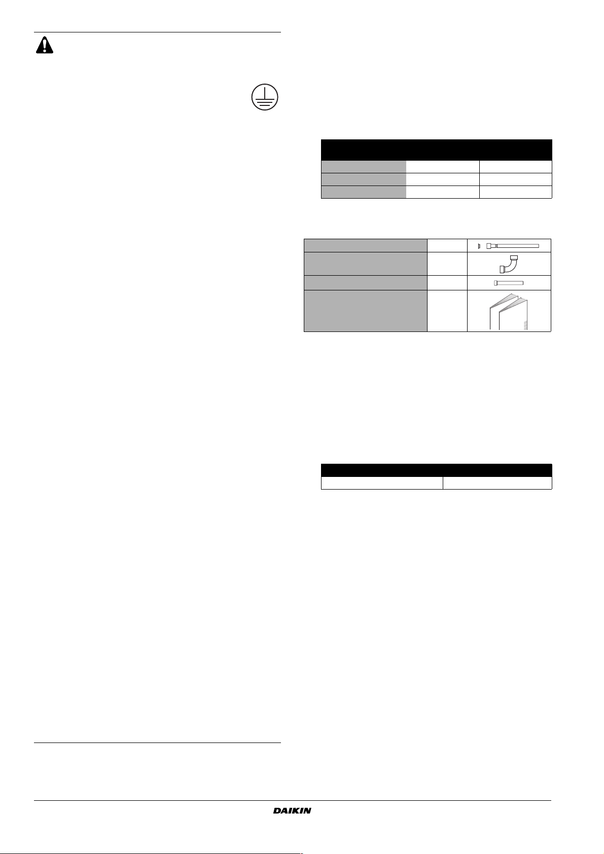
■ Total capacity/quantity of indoor units
Outdoor unit
RXYSQ4 50~130 6
RXYSQ5 62.5~162.5 8
RXYSQ6 70~182 9
Total capacity of
indoor units
2.2. Standard supplied accessories
Gas line piping (1)
Gas line piping (2)(*)
Gas line piping (3)(*)
Installation manual
Operation manual
(*) Only for RXYSQ6.
(*)
+ copper gasket
Location of accessories: refer to figure 1.
1 Accessories
1
1
1
1
1
2.3. Optional accessories
To install the above outdoor units, the following optional parts are
also required.
■ Refrigerant branching kit (for R-410A only: Always use an
appropriate kit dedicated for your system.)
Refnet header Refnet joint
KHRQ22M29H KHRQ22M20T
To select an optimum refrigerant branching kit, refer to "Refrigerant
branch kit selection" on page 9.
2.4. Technical and electrical specifications
Refer to the Engineering Data Book for the complete list of
specifications.
Total quantity of
indoor units
+
Installation manual
2
VRVII-S system air conditioner
RXYSQ4~6M7V3B
4PW17806-1C
3. BEFORE INSTALLATION
Since design pressure is 3.8 MPa or 38 bar, pipes of larger
wall thickness may be required. Refer to paragraph
"7.1. Selection of piping material" on page 5.
3.1. Precautions for R-410A
■ The refrigerant requires strict cautions for keeping the system
clean, dry and tight.
- Clean and dry
Foreign materials (including mineral oils or moisture) should be
prevented from getting mixed into the system.
- Tight
Read "8. Precautions on refrigerant piping" on page 6 carefully
and follow these procedures correctly.
■ Since R-410A is a mixed refrigerant, the required additional
refrigerant must be charged in its liquid state. (If the refrigerant
is in state of gas, its composition changes and the system will
not work properly).
■ The connected indoor units must be indoor units designed
exclusively for R-410A.
3.2. Installation
■ For installation of the indoor unit(s), refer to the indoor unit
installation manual.
■ Never operate the air conditioner with the discharge pipe
thermister (R3T), suction pipe thermister (R2T) and pressure
sensors (S1NPH, S1NPL) removed. Such operation may burn
out the compressor.
■ Be sure to confirm the model name and the serial no. of the
outer (front) plates when attaching/detaching the plates to avoid
mistakes.
■ When closing the service panels, take care that the tightening
torque does not exceed 4.1 N•m.
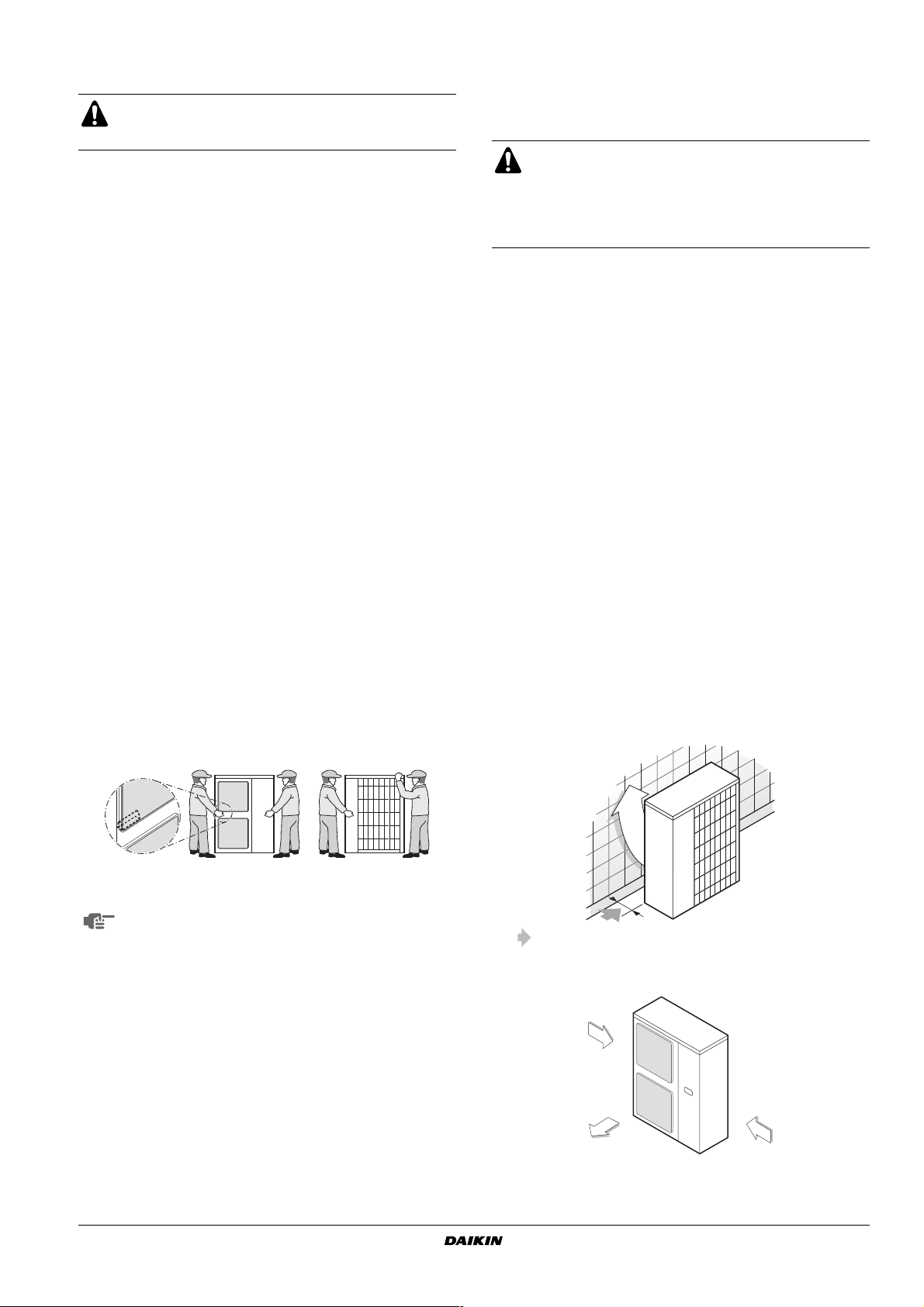
3.3. Handling
As shown in the figure, bring the unit slowly by grabbing the left and
right grips.
4. SELECTING INSTALLATION SITE
This is a class A product. In a domestic environment this product may
cause radio interference in which case the user may be required to
take adequate measures.
■ Make sure to provide for adequate measures in order
to prevent that the outdoor unit be used as a shelter
by small animals.
■ Small animals making contact with electrical parts can
cause malfunctions, smoke or fire. Please instruct the
customer to keep the area around the unit clean.
1 Select an installation site where the following conditions are
satisfied and that meets with your customer's approval.
- Places which are well-ventilated.
- Places where the unit does not bother next-door neighbours.
- Safe places which can withstand the unit's weight and
vibration and where the unit can be installed level.
- Places where there is no possibility of flammable gas or
product leak.
- Places where servicing space can be well ensured.
- Places where the indoor and outdoor units' piping and wiring
lengths come within the allowable ranges.
- Places where water leaking from the unit cannot cause
damage to the location (e.g. in case of a blocked drain pipe).
- Places where the rain can be avoided as much as possible.
2 When installing the unit in a place exposed to strong wind, pay
special attention to the following.
Strong winds of 5 m/sec or more blowing against the outdoor
unit's air outlet causes short circuit (suction of discharge air),
and this may have the following consequences:
- Deterioration of the operational capacity.
-Frequent frost acceleration in heating operation.
- Disruption of operation due to rise of high pressure.
- When a strong wind blows continuously on the face of the
unit, the fan can start rotating very fast until it breaks.
Refer to the figures for installation of this unit in a place where
the wind direction can be foreseen.
■ Tu rn the air outlet side toward the building's wall, fence or
screen.
Place your hands on the corner instead of holding the suction inlet in
the side of the casing, otherwise the casing could be deformed.
Ta ke care not to let hands or objects come in contact with
rear fins.
RXYSQ4~6M7V3B
VRVII-S system air conditioner
4PW17806-1C
Make sure there is enough room to do the installation
■ Set the outlet side at a right angle to the direction of the wind.
Strong wind
Blown air Strong wind
3 Prepare a water drainage channel around the foundation, to
drain waste water from around the unit.
Installation manual
3
4 If the water drainage of the unit is not easy, please build up the
unit on a foundation of concrete blocks, etc. (the height of the
foundation should be maximum 150 mm).
5 If you install the unit on a frame, please install a waterproof plate
within 150 mm of the underside of the unit in order to prevent the
invasion of water from the lower direction.
6 When installing the unit in a place frequently exposed to snow,
pay special attention to the following:
- Elevate the foundation as high as possible.
- Remove the rear suction grille to prevent snow from
accumulating on the rear fins.
7 If you install the unit on a building frame,
please install a waterproof plate (within
150 mm of the underside of the unit) or
use a drain plug kit (option) in order to
avoid the drainwater dripping.
The equipment described in this manual may cause
electronic noise generated from radio-frequency energy.
The equipment complies to specifications that are
designed to provide reasonable protection against such
interference. However, there is no guarantee that
interference will not occur in a particular installation.
It is therefore recommended to install the equipment and
electric wires keeping proper distances away from stereo
equipment, personal computers, etc... (See figure 2)
1 Personal computer or radio
2 Fuse
3 Earth leak detector
4 Remote controller
5 Cool/heat selector
6 Indoor unit
In extreme circumstances you should keep distances of
3 m or more and use conduit tubes for power and
transmission lines.
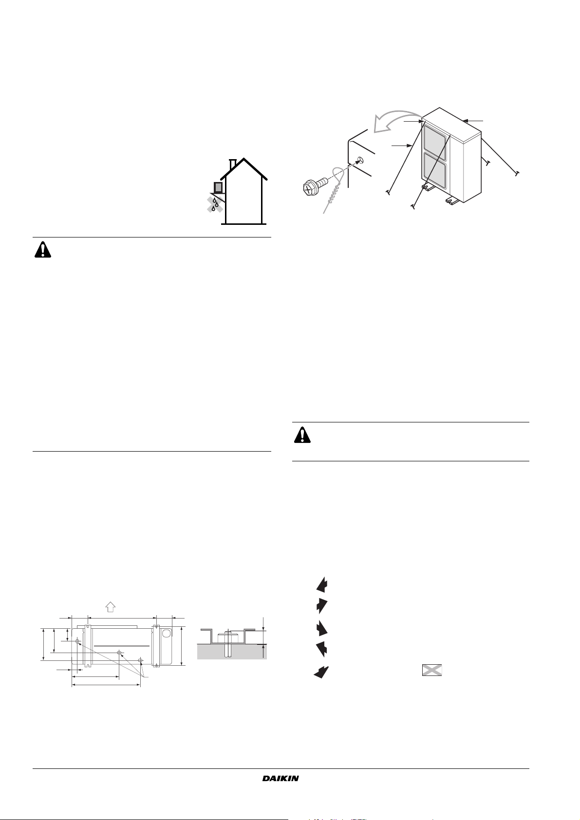
5.1. Installation method for prevention of falling over
If it is necessary to prevent the unit from falling over, install as shown
in the figure.
■ prepare all 4 wires as indicated in the drawing
■ unscrew the top plate at the 4 locations indicated A and B
■ put the screws through the nooses and screw them back tight
AA
B
C
A location of the 2 fixation holes on the front side of the unit
B location of the 2 fixation holes on the rear side of the unit
C wires: field supply
5.2. Method for removing transport fittings
The transportation fittings (2 yellow pieces) are provided on the leg of
the compressor for protecting the unit during transport. Remove them
as shown in figure 3 and described below.
A Compressor
B Fixing nut
C Transport fitting
1 Slightly loosen each fixing nut (B).
2 Remove each transport fitting (C) as shown in figure 3.
3 Tighten each fixing nut (B) again.
CAUTION
If the unit is operated with the transport fittings attached,
abnormal vibration or noise may be generated.
5. PRECAUTIONS ON INSTALLATION
■ Check the strength and level of the installation ground so that
the unit will not cause any operating vibration or noise after
installation.
■ In accordance with the foundation drawing in the figure, fix the
unit securely by means of the foundation bolts. (Prepare four
sets of M12 foundation bolts, nuts and washers each which are
available on the market.)
■ It is best to screw in the foundation bolts until their length are
20 mm from the foundation surface.
A
140
117
219
289
45
A Discharge side
B Bottom view (mm)
C Drain hole
B
421
612
140620
350
(345-355)
C
20
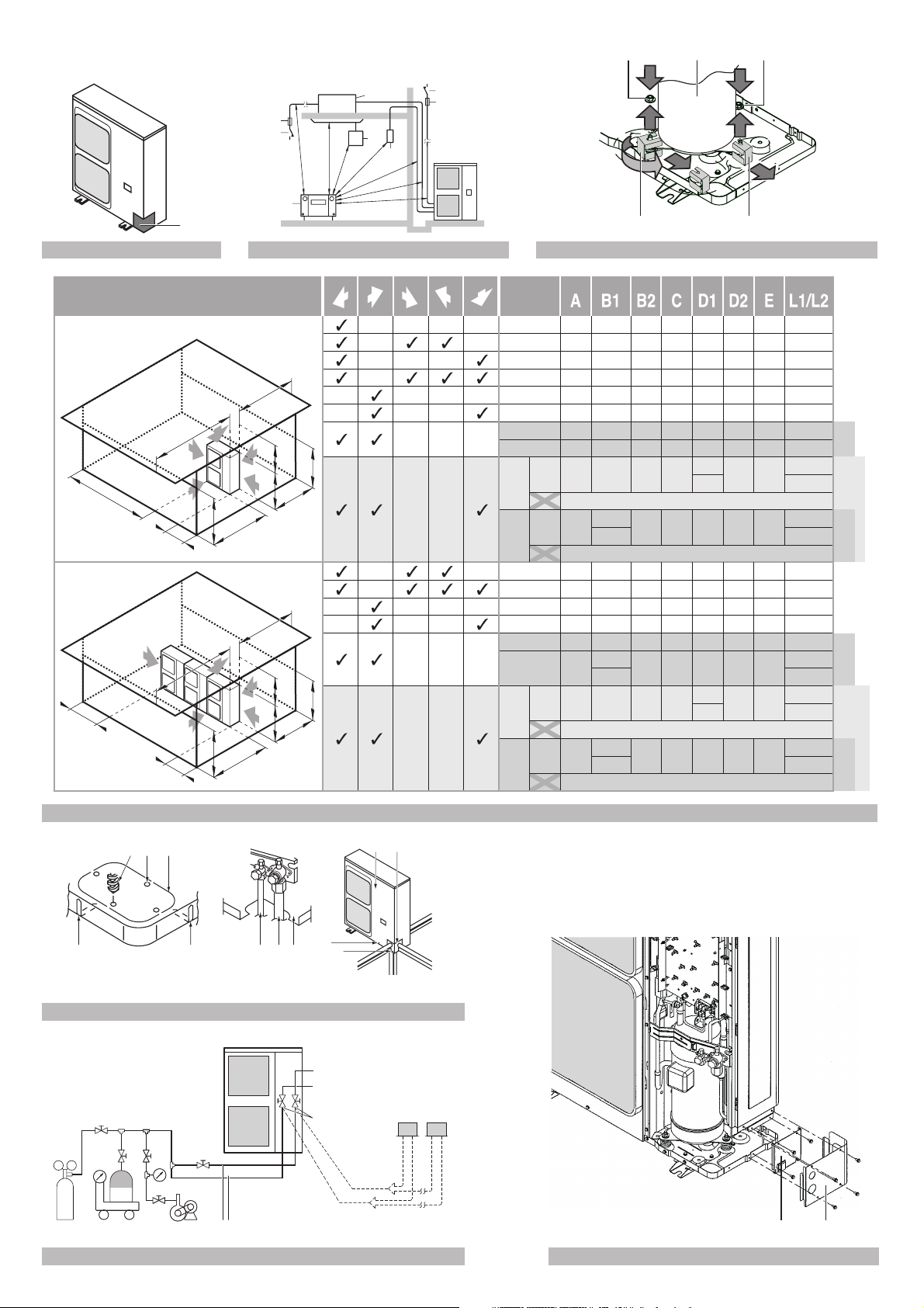
6. INSTALLATION SERVICING SPACE
■ The connection piping outlet direction in the installation shown in
figure 4 is frontward or downward. The unit of numeric values is
mm.
■ When routing the piping backward, secure space of ≥250 mm on
the right side of the unit.
(A) In case of non-stacked installation (See figure 4)
In these cases, close the
Suction side obstacle
Discharge side obstacle
Left side obstacle
Right side obstacle
Top side obstacle
Obstacle is present
✓
1
bottom of the installation
frame to prevent the
discharged air from
being bypassed
In these cases, only 2
2
units can be installed.
In these cases, no
3
restriction of height L1.
This situation is not
allowed
Installation manual
4
VRVII-S system air conditioner
RXYSQ4~6M7V3B
4PW17806-1C
 Loading...