

Installation and operation manual
CO₂ Conveni-Pack outdoor unit and capacity up unit
LRYEN10A7Y1
LRNUN5A7Y1
Installation and operation manual
CO₂ Conveni-Pack outdoor unit and capacity up unit
English
(mm)
≥300 ≥500
≥500
≥10
B
B1 B2 B3
≥100 ≥500
≥500
≥50
≥300
≥200
a
a
C1 C2 C3
C
a
≥300 ≥500
≥20
≥10 ≥50
≥100 ≥500
≥100
≥300
≥400
≥200
a
A
YX
h2
H2
500
h1
H1
1500
1

Table of contents
Table of contents
1 About the documentation 3
1.1 About this document.................................................................. 3
2 Specific installer safety instructions 4
For the user 5
3 User safety instructions 5
3.1 General...................................................................................... 6
3.2 Instructions for safe operation ................................................... 6
4 About the system 8
4.1 System layout............................................................................ 8
5 Operation 8
5.1 Operation range ........................................................................ 8
5.2 Design pressure ........................................................................ 8
6 Maintenance and service 9
6.1 About the refrigerant.................................................................. 9
6.2 Recommended maintenance and inspection ............................ 9
7 Troubleshooting 9
7.1 Error codes: Overview............................................................... 10
8 Relocation 10
9 Disposal 10
For the installer 10
10 About the box 10
10.1 Outdoor unit............................................................................... 10
10.1.1 To unpack the outdoor unit ......................................... 10
10.1.2 To handle the outdoor unit .......................................... 10
10.1.3 To remove the accessories from the outdoor unit....... 11
11 About the units and options 11
11.1 About the outdoor unit ............................................................... 11
11.1.1 Labels on outdoor unit ................................................ 12
11.2 System layout ............................................................................ 12
11.3 Indoor unit constraints ............................................................... 13
12 Unit installation 13
12.1 Preparing the installation site .................................................... 13
12.1.1 Installation site requirements of the outdoor unit ........ 13
12.1.2 Additional installation site requirements of the
outdoor unit in cold climates ....................................... 13
12.1.3 Additional installation site requirements for CO₂
refrigerant.................................................................... 13
12.2 Opening and closing the unit ..................................................... 14
12.2.1 To open the outdoor unit ............................................. 14
12.2.2 To open the electrical component box of the outdoor
unit .............................................................................. 15
12.2.3 To close the outdoor unit ............................................ 15
12.3 Mounting the outdoor unit.......................................................... 16
12.3.1 To provide the installation structure ............................ 16
12.3.2 To install the outdoor unit............................................ 17
12.3.3 To provide drainage .................................................... 17
13.1.5 To select refrigerant branch kits................................... 20
13.1.6 To select expansion valves for refrigeration ................ 20
13.2 Using stop valves and service ports ........................................... 20
13.2.1 To handle the stop valve .............................................. 20
13.2.2 To handle the service port ........................................... 21
13.2.3 Tightening torques ....................................................... 21
13.3 Connecting the refrigerant piping ............................................... 22
13.3.1 To remove the spun pipes ........................................... 22
13.3.2 To connect the refrigerant piping to the outdoor unit ... 22
13.3.3 Guidelines to connect T-joints...................................... 23
13.3.4 Guidelines to install a dryer.......................................... 23
13.3.5 Guidelines to install safety valves ................................ 23
13.4 Checking the refrigerant piping .................................................. 24
13.4.1 Checking refrigerant piping: Setup............................... 24
13.4.2 To perform a leak test .................................................. 24
13.4.3 To perform vacuum drying ........................................... 24
13.5 Insulating the refrigerant piping .................................................. 24
14 Electrical installation 25
14.1 About electrical compliance........................................................ 25
14.2 Field wiring: Overview ................................................................ 26
14.3 Guidelines when knocking out knockout holes........................... 27
14.4 Guidelines when connecting the electrical wiring ....................... 27
14.5 Specifications of standard wiring components ........................... 27
14.6 Connections to the outdoor unit ................................................. 28
14.6.1 Low voltage wiring – Outdoor unit................................ 28
14.6.2 High voltage wiring – Outdoor unit ............................... 29
14.7 Connections to the capacity up unit ........................................... 29
14.7.1 Low voltage wiring – Capacity up unit.......................... 30
14.7.2 High voltage wiring – Capacity up unit ......................... 30
15 Charging refrigerant 31
15.1 Precautions when charging refrigerant....................................... 31
15.2 To determine additional refrigerant amount ............................... 32
15.3 To charge refrigerant .................................................................. 32
16 Configuration 33
16.1 Making field settings ................................................................... 33
16.1.1 About making field settings .......................................... 33
16.1.2 To access the field setting components ....................... 33
16.1.3 Field setting components ............................................. 33
16.1.4 To access mode 1 or 2 ................................................ 33
17 Commissioning 34
17.1 Precautions when commissioning .............................................. 34
17.2 Checklist before commissioning ................................................. 34
17.3 About the test run ....................................................................... 35
17.4 To perform a test run (7-segment display) ................................. 35
17.4.1 Test run checks............................................................ 35
17.4.2 Correcting after abnormal completion of the test run ... 36
17.5 Logbook...................................................................................... 36
18 Troubleshooting 37
18.1 Solving problems based on error codes ..................................... 37
18.1.1 Error codes: Overview ................................................. 37
19 Technical data 40
19.1 Piping diagram: Outdoor unit...................................................... 40
19.2 Piping diagram: Capacity up unit................................................ 41
19.3 Wiring diagram: Outdoor unit ..................................................... 42
1 About the documentation
13 Piping installation 17
13.1 Preparing refrigerant piping ....................................................... 17
13.1.1 Refrigerant piping requirements.................................. 17
13.1.2 Refrigerant piping material .......................................... 17
13.1.3 Refrigerant piping length and height difference .......... 18
13.1.4 To select the piping size ............................................. 18
LRYEN10A7Y1+LRNUN5A7Y1
CO₂ Conveni-Pack outdoor unit and capacity up unit
4P605461-1B – 2020.08
1.1 About this document
Target audience
Authorised installers + end users
Installation and operation manual
3
2 Specific installer safety instructions
INFORMATION
This appliance is intended to be used by expert or trained
users in shops, in light industry and on farms, or for
commercial use by lay persons.
Documentation set
This document is part of a documentation set. The complete set
consists of:
▪ General safety precautions:
▪ Safety instructions that you must read before installing
▪ Format: Paper (in the box of the outdoor unit)
▪ Installation and operation manual of the outdoor unit:
▪ Installation and operation instructions
▪ Format: Paper (in the box of the outdoor unit)
▪ Installer and user reference guide of the outdoor unit:
▪ Preparation of the installation, reference data,…
▪ Detailed step-by-step instructions and background information
for basic and advanced usage
▪ Format: Digital files on http://www.daikineurope.com/support-
and-manuals/product-information/
Latest revisions of the supplied documentation may be available on
the regional Daikin website or via your dealer.
The original documentation is written in English. All other languages
are translations.
Installation site (see "12.1Preparing the installation
site"[413])
CAUTION
Appliance not accessible to the general public, install it in a
secured area, protected from easy access.
This unit, both indoor and outdoor, is suitable for
installation in a commercial and light industrial
environment.
WARNING
All installed safety valves MUST ventilate to the outdoor
space and NOT into a closed area.
CAUTION
If the safety valve operates, CO2 gas may concentrate
inside the casing of the outdoor unit. Therefore, you should
ALWAYS take a distance for your own safety. You can
close the outdoor unit if your portable CO2 detector
confirmed that the concentration of CO2 is at an acceptable
level. For example, if 7 kg CO2 is released inside the
casing, it takes around 5minutes until the concentration of
CO2 is low enough.
WARNING
Do NOT place objects below the indoor and/or outdoor unit
that may get wet. Otherwise condensation on the main unit
or refrigerant pipes, air filter dirt or drain blockage may
cause dripping, and objects under the unit may get dirty or
damaged.
2 Specific installer safety
instructions
Always observe the following safety instructions and regulations.
CAUTION
Do NOT insert fingers, rods or other objects into the air
inlet or outlet. When the fan is rotating at high speed, it will
cause injury.
General installation requirements
WARNING
▪ Make sure to install all necessary countermeasures in
case of refrigerant leakage according to standard
EN378 (see "12.1.3 Additional installation site
requirements for CO₂ refrigerant"[413]).
▪ Make sure to install a CO2 leak detector (field supply)
and enable the function for refrigerant leak detection
(see the installation manual of the indoor unit (air
conditioning)).
WARNING
Make sure installation, servicing, maintenance, repair and
applied materials follow the instructions from Daikin and, in
addition, comply with applicable legislation and are
performed by qualified persons only. In Europe and areas
where IEC standards apply, EN/IEC 60335-2-40 is the
applicable standard.
WARNING
Install the unit only in locations where the doors of the
occupied space are not tight fitting.
NOTICE
Serious injury and/or damage can result from blow off of
the liquid receiver safety valve (see "19.1 Piping diagram:
Outdoor unit"[440]):
▪ NEVER service the unit when the pressure at the liquid
receiver is higher than the set pressure of the liquid
receiver safety valve (86barg±3%). If this safety valve
releases refrigerant, it can cause serious injury and/or
damage.
▪ If the pressure >86 bar, ALWAYS discharge from
pressure relief devices before servicing.
▪ It is recommended to install and secure blow off piping
to the safety valve.
▪ Remove the refrigerant before altering the safety valve
position.
NOTICE
Adverse effects shall be considered. For example, danger
of water collecting and freezing in discharge pipes for
pressure relief devices, accumulation of dirt and debris, or
blockage of the discharge pipes by solid CO2 (R744).
INFORMATION
Instructions on how to fix the unit in a correct way can be
found in "12Unit installation"[413].
Installation and operation manual
4
CO₂ Conveni-Pack outdoor unit and capacity up unit
LRYEN10A7Y1+LRNUN5A7Y1
4P605461-1B – 2020.08
3 User safety instructions
Refrigerant piping installation (see "13Piping
installation"[417])
WARNING
▪ Only use R744 (CO2) as refrigerant. Other substances
may cause explosions and accidents.
▪ When installing, charging refrigerant, maintaining or
performing service, ALWAYS use personal protective
equipment, such as safety shoes, safety gloves and
safety glasses.
▪ If the unit is installed indoors (for example, in a
machine room), ALWAYS use a portable CO2 detector.
▪ If the front panel is open, ALWAYS beware of the
rotating fan. The fan will continue rotating for a while,
even after the power switch has been turned off.
CAUTION
Do NOT reuse piping from previous installations.
CAUTION
Install the refrigerant piping or components in a position
where they are unlikely to be exposed to any substance
which may corrode components containing refrigerant,
unless the components are constructed of materials that
are inherently resistant to corrosion or are suitably
protected against corrosion.
WARNING
▪ Use K65 piping for high-pressure applications with a
working pressure of 120bar or 90bar, depending on its
location in the system.
▪ Use K65 unions and fittings approved for a working
pressure of 120bar or 90bar, depending on its location
in the system.
▪ Only brazing is allowed for connection of pipes. No
other types of connections are allowed.
▪ Expanding of pipes is not allowed.
INFORMATION
To complete the refrigerating system, additional charging
of refrigerant is required. See "15 Charging
refrigerant"[431].
Electrical installation (see "14Electrical installation"[425])
WARNING
▪ If the power supply has a missing or wrong N-phase,
equipment might break down.
▪ Establish proper earthing. Do NOT earth the unit to a
utility pipe, surge absorber, or telephone earth.
Incomplete earthing may cause electrical shock.
▪ Install the required fuses or circuit breakers.
▪ Secure the electrical wiring with cable ties so that the
cables do NOT come in contact with sharp edges or
piping, particularly on the high-pressure side.
▪ Do NOT use taped wires, stranded conductor wires,
extension cords, or connections from a star system.
They can cause overheating, electrical shock or fire.
▪ Do NOT install a phase advancing capacitor, because
this unit is equipped with an inverter. A phase
advancing capacitor will reduce performance and may
cause accidents.
WARNING
▪ All wiring MUST be performed by an authorised
electrician and MUST comply with the applicable
legislation.
▪ Make electrical connections to the fixed wiring.
▪ All components procured on-site and all electrical
construction MUST comply with the applicable
legislation.
WARNING
ALWAYS use multicore cable for power supply cables.
WARNING
Use an all-pole disconnection type breaker with at least
3 mm between the contact point gaps that provide full
disconnection under overvoltage category III.
WARNING
If the supply cord is damaged, it MUST be replaced by the
manufacturer, its service agent or similarly qualified
persons in order to avoid a hazard.
INFORMATION
A wiring diagram can be found on the applicance and its
description of the connections and wiring to external
control devices and supply cord can be found in
"19.3Wiring diagram: Outdoor unit"[442].
For the user
3 User safety instructions
Always observe the following safety instructions and regulations.
LRYEN10A7Y1+LRNUN5A7Y1
CO₂ Conveni-Pack outdoor unit and capacity up unit
4P605461-1B – 2020.08
INFORMATION
The method of connection of the appliance to the electrical
supply and interconnection of separate components is
described in "14.2Field wiring: Overview"[426].
INFORMATION
Details of type and rating of fuses, or rating of circuit
breakers are described in "14Electrical installation"[425].
Installation and operation manual
5

3 User safety instructions
3.1 General
WARNING
If you are NOT sure how to operate the
unit, contact your installer.
WARNING
Children aged from 8 years and above
and persons with reduced physical,
sensory or mental capabilities or lack
of experience and knowledge can only
use this appliance if they have been
given supervision or instruction
concerning the use of the appliance by
a person responsible for their safety.
Children MUST NOT play with the
appliance.
Cleaning and user maintenance MUST
NOT be carried out by children without
supervision.
WARNING
To prevent electrical shocks or fire:
▪ Do NOT rinse the unit.
▪ Do NOT operate the unit with wet
hands.
▪ Do NOT place any objects containing
water on the unit.
CAUTION
▪ Do NOT place any objects or
equipment on top of the unit.
▪ Batteries are marked with the following symbol:
This means that the batteries may NOT be mixed with unsorted
household waste. If a chemical symbol is printed beneath the
symbol, this chemical symbol means that the battery contains a
heavy metal above a certain concentration.
Possible chemical symbols are: Pb: lead (>0.004%).
Waste batteries must be treated at a specialized treatment facility
for reuse. By ensuring waste batteries are disposed of correctly,
you will help to prevent potential negative consequences for the
environment and human health.
3.2 Instructions for safe operation
WARNING
Do NOT modify, disassemble, remove,
reinstall or repair the unit yourself as
incorrect dismantling or installation
may cause an electric shock or fire.
Contact your dealer.
CAUTION
If this unit is equipped with an
electrically powered safety measure,
such as a CO2 refrigerant leak detector
(field supply), in order to be effective,
the unit must be electrically powered at
all times after installation, except for
short service periods.
CAUTION
Do NOT insert fingers, rods or other
objects into the air inlet or outlet. When
the fan is rotating at high speed, it will
cause injury.
▪ Do NOT sit, climb or stand on the
unit.
▪ Units are marked with the following symbol:
This means that electrical and electronic products may NOT be
mixed with unsorted household waste. Do NOT try to dismantle
the system yourself: the dismantling of the system, treatment of
the refrigerant, of oil and of other parts must be done by an
authorized installer and must comply with applicable legislation.
Units must be treated at a specialized treatment facility for reuse,
recycling and recovery. By ensuring this product is disposed of
correctly, you will help to prevent potential negative consequences
for the environment and human health. For more information,
contact your installer or local authority.
Installation and operation manual
6
CAUTION
▪ NEVER touch the internal parts of the
controller.
▪ Do NOT remove the front panel.
Some parts inside are dangerous to
touch and appliance problems may
happen. For checking and adjusting
the internal parts, contact your
dealer.
WARNING
This unit contains electrical and hot
parts.
LRYEN10A7Y1+LRNUN5A7Y1
CO₂ Conveni-Pack outdoor unit and capacity up unit
4P605461-1B – 2020.08
3 User safety instructions
WARNING
Before operating the unit, be sure the
installation has been carried out
correctly by an installer.
CAUTION
It is not good for your health to expose
your body to the air flow for a long
time.
CAUTION
To avoid oxygen deficiency, ventilate
the room sufficiently if equipment with
burner is used together with the
system.
CAUTION
Do NOT operate the system when
using a room fumigation-type
insecticide. Chemicals could collect in
the unit, and endanger the health of
people who are hypersensitive to
chemicals.
CAUTION
NEVER expose little children, plants or
animals directly to the airflow.
WARNING
Do NOT place objects below the indoor
and/or outdoor unit that may get wet.
Otherwise condensation on the main
unit or refrigerant pipes, air filter dirt or
drain blockage may cause dripping,
and objects under the unit may get
dirty or damaged.
WARNING
Do NOT place a flammable spray
bottle near the air conditioner and do
NOT use sprays near the unit. Doing
so may result in a fire.
Maintenance and service (see "6Maintenance and
service"[49])
WARNING: System contains
refrigerant under very high
pressure.
The system MUST be serviced by
qualified persons only.
CAUTION: Pay attention to the fan!
It is dangerous to inspect the unit while
the fan is running.
Be sure to turn off the main switch
before executing any maintenance
task.
WARNING
Never replace a fuse with a fuse of a
wrong ampere ratings or other wires
when a fuse blows out. Use of wire or
copper wire may cause the unit to
break down or cause a fire.
CAUTION
After a long use, check the unit stand
and fitting for damage. If damaged, the
unit may fall and result in injury.
CAUTION
Before accessing terminal devices,
make sure to interrupt all power supply.
DANGER: RISK OF
ELECTROCUTION
To clean the air conditioner or air filter,
be sure to stop operation and turn all
power supplies off. Otherwise, an
electric shock and injury may result.
WARNING
Be careful with ladders when working
in high places.
WARNING
Do NOT let the indoor unit get wet.
Possible consequence: Electric
shock or fire.
About the refrigerant (see "6.1About the refrigerant"[49])
WARNING
▪ Do NOT pierce or burn refrigerant
cycle parts.
▪ Do NOT use cleaning materials other
than those recommended by the
manufacturer.
▪ Be aware that the refrigerant inside
the system is odourless.
LRYEN10A7Y1+LRNUN5A7Y1
CO₂ Conveni-Pack outdoor unit and capacity up unit
4P605461-1B – 2020.08
Installation and operation manual
7
4 About the system
ab
e e
d c
f
h
i
j
k
h
l
i
j
k
l
g
WARNING
The R744 refrigerant (CO2) inside the
unit is odourless, non-flammable and
normally does NOT leak.
If the refrigerant leaks in high
concentrations in the room, it may have
negative effects on its occupants such
as asphyxiation and carbon dioxide
poisoning. Ventilate the room and
contact the dealer where you
purchased the unit.
Do NOT use the unit until a service
person confirms that the part from
which the refrigerant leaked has been
repaired.
Troubleshooting (see "7Troubleshooting"[49])
WARNING
Stop operation and shut off the
power if anything unusual occurs
(burning smells etc.).
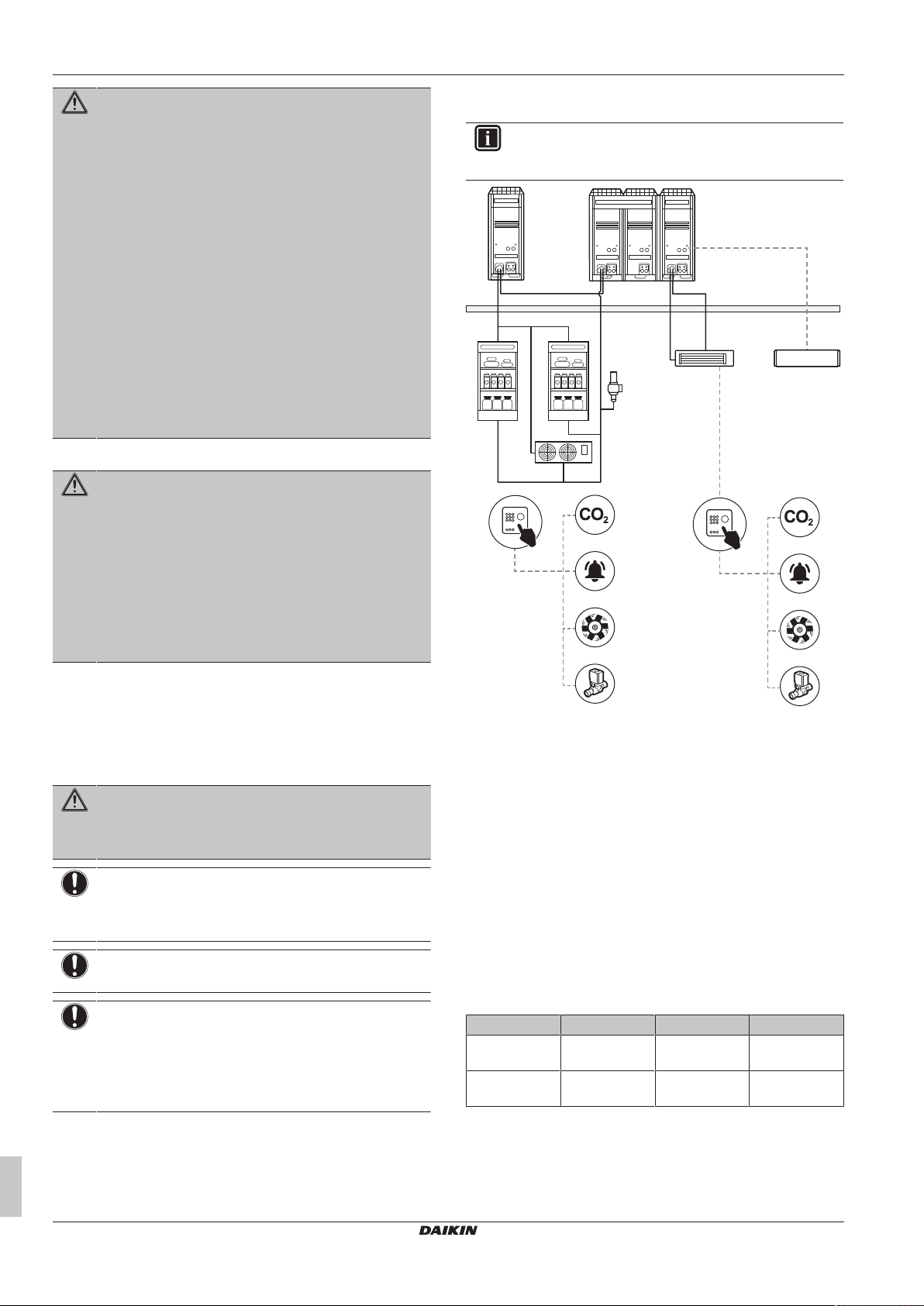
4.1 System layout
INFORMATION
The following illustration is an example and might NOT
match your system layout.
4 About the system
The indoor units can be used for heating/cooling and refrigerating
applications. The type of indoor units which can be used depends on
the outdoor units series.
Leaving the unit running under such
circumstances may cause breakage,
electric shock or fire. Contact your
dealer.
WARNING
Do NOT modify, disassemble, remove, reinstall or repair
the unit yourself as incorrect dismantling or installation may
cause an electric shock or fire. Contact your dealer.
NOTICE
Do NOT use the system for other purposes. In order to
avoid any quality deterioration, do NOT use the unit for
cooling precision instruments or works of art.
NOTICE
Do NOT use the system for cooling water. It may freeze.
NOTICE
For future modifications or expansions of your system:
A full overview of allowable combinations (for future
system extensions) is available in technical engineering
data and should be consulted. Contact your installer to
receive more information and professional advice.
a Main outdoor unit (LRYEN10*)
b Capacity up unit (LRNUN5*)
c Communication box (BRR9B1V1)
d Fan (indoor unit for air conditioning)
e Showcase (indoor unit for refrigeration)
f Blower coil (indoor unit for refrigeration)
g Safety valve
h CO2 control panel
i CO2 detector
j CO2 alarm
k CO2 ventilator
l Shut off valve
5 Operation
5.1 Operation range
Use the system in the following temperature ranges for safe and
effective operation.
Refrigeration A/C cooling A/C heating
Outdoor
temperature
Indoor
temperature
5.2 Design pressure
Always keep the following design pressures in mind:
–20~43°CDB –5~43°CDB –20~16°CWB
— 14~24°CWB 15~27°CDB
Installation and operation manual
8
CO₂ Conveni-Pack outdoor unit and capacity up unit
LRYEN10A7Y1+LRNUN5A7Y1
4P605461-1B – 2020.08
6 Maintenance and service
Side Design pressure
Refrigeration 90bar
Air conditioning 120bar
6 Maintenance and service
NOTICE
Never inspect or service the unit by yourself. Ask a
qualified service person to perform this work.
WARNING
Never replace a fuse with a fuse of a wrong ampere ratings
or other wires when a fuse blows out. Use of wire or
copper wire may cause the unit to break down or cause a
fire.
CAUTION
Do NOT insert fingers, rods or other objects into the air
inlet or outlet. Do NOT remove the fan guard. When the
fan is rotating at high speed, it will cause injury.
CAUTION
After a long use, check the unit stand and fitting for
damage. If damaged, the unit may fall and result in injury.
NOTICE
Do NOT wipe the controller operation panel with benzine,
thinner, chemical dust cloth, etc. The panel may get
discoloured or the coating peeled off. If it is heavily dirty,
soak a cloth in water-diluted neutral detergent, squeeze it
well and wipe the panel clean. Wipe it with another dry
cloth.
6.1 About the refrigerant
This product contains refrigerant gases.
Refrigerant type: R744 (CO2)
WARNING
▪ Do NOT pierce or burn refrigerant cycle parts.
▪ Do NOT use cleaning materials other than those
recommended by the manufacturer.
▪ Be aware that the refrigerant inside the system is
odourless.
WARNING
The R744 refrigerant (CO2) inside the unit is odourless,
non-flammable and normally does NOT leak.
If the refrigerant leaks in high concentrations in the room, it
may have negative effects on its occupants such as
asphyxiation and carbon dioxide poisoning. Ventilate the
room and contact the dealer where you purchased the unit.
Do NOT use the unit until a service person confirms that
the part from which the refrigerant leaked has been
repaired.
6.2 Recommended maintenance and inspection
Since dust collects when using the unit for several years,
performance of the unit will deteriorate to some extent. As taking
apart and cleaning interiors of units requires technical expertise and
in order to ensure the best possible maintenance of your units, we
recommend to enter into a maintenance and inspection contract on
top of normal maintenance activities. Our network of dealers has
access to a permanent stock of essential components in order to
keep your unit in operation as long as possible. Contact your dealer
for more information.
When asking your dealer for an intervention, always state:
▪ The complete model name of the unit.
▪ The manufacturing number (stated on the nameplate of the unit).
▪ The installation date.
▪ The symptoms or malfunction, and details of the defect.
WARNING
▪ Do NOT modify, disassemble, remove, reinstall or
repair the unit yourself as incorrect dismantling or
installation may cause an electric shock or fire. Contact
your dealer.
▪ In case of accidental refrigerant leaks, make sure there
are no naked flames. The refrigerant itself is entirely
safe, non-toxic and non-combustible, but it will
generate toxic gas when it accidentally leaks into a
room where combustible air from fan heaters, gas
cookers, etc. is present. Always have qualified service
personnel confirm that the point of leakage has been
repaired or corrected before resuming operation.
7 Troubleshooting
If system malfunctions are likely to degrade the articles in the room/
showcase, you can ask your installer to install an alarm (example:
lamp). For more information, contact your installer.
If one of the following malfunctions occur, take the measures shown
below and contact your dealer.
WARNING
Stop operation and shut off the power if anything
unusual occurs (burning smells etc.).
Leaving the unit running under such circumstances may
cause breakage, electric shock or fire. Contact your dealer.
The system MUST be repaired by a qualified service person.
Malfunction Measure
If a safety device such as a fuse, a
breaker or an earth leakage breaker
frequently actuates or the ON/OFF
switch does NOT properly work.
If water leaks from the unit. Stop the operation.
The operation switch does NOT work
well.
If the user interface display indicates the
unit number, the operation lamp flashes
and the malfunction code appears.
If the system does NOT operate properly except for the above
mentioned cases and none of the above mentioned malfunctions is
evident, investigate the system in accordance with the following
procedures.
If after checking all above items, it is impossible to fix the problem
yourself, contact your installer and state the symptoms, the complete
model name of the unit (with manufacturing number if possible) and
the installation date (possibly listed on the warranty card).
Turn OFF the main power
switch.
Turn OFF the power
supply.
Notify your installer and
report the malfunction
code.
LRYEN10A7Y1+LRNUN5A7Y1
CO₂ Conveni-Pack outdoor unit and capacity up unit
4P605461-1B – 2020.08
Installation and operation manual
9
8 Relocation
a b
8×8×
a b
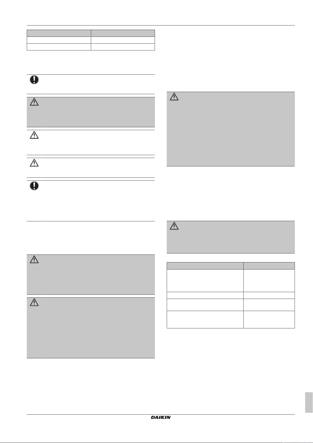
7.1 Error codes: Overview
In case a malfunction code appears on the indoor unit user interface
display, contact your installer and inform the malfunction code, the
unit type, and serial number (you can find this information on the
nameplate of the unit).
For your reference, a list with malfunction codes is provided. You
can, depending on the level of the malfunction code, reset the code
by pushing the ON/OFF button. If not, ask your installer for advice.
Code Cause Solution
Electric leakage Restart the unit by
switching operating switch
OFF and ON.
The stop valve of an
outdoor unit is left closed.
The stop valve of an
outdoor unit is left closed.
The air passage is blocked. Remove obstacles that
Lost phase in power
supply.
Insufficient supply voltage Check if the supply voltage
Wrong transmission wiring
between units
Open the stop valve on
both the gas and liquid
side.
Open the stop valve on
both the gas and liquid
side.
block the passage of air to
the outdoor unit.
Check the connection of
the power supply cable.
is supplied properly.
Check the connection of
transmission wiring
between the outdoor unit
and the air conditioner.
Code Cause Solution
Wrong combination of
indoor units
Wrong transmission wiring
between units
Refer to the service manual for other malfunction codes.
If no malfunction code is displayed, check if
▪ power of indoor unit is turned on,
▪ user interface wiring is broken or incorrectly wired,
▪ fuse on PCB has melted.
▪ Check the number of
connected indoor units.
▪ Check if an indoor unit is
installed that is not a
possible combination.
Check the connection of
transmission wiring
between the outdoor unit
and the air conditioner.
8 Relocation
Contact your dealer for removing and reinstalling the total unit.
Moving units requires technical expertise.
9 Disposal
NOTICE
Do NOT try to dismantle the system yourself: dismantling
of the system, treatment of the refrigerant, oil and other
parts MUST comply with applicable legislation. Units
MUST be treated at a specialised treatment facility for
reuse, recycling and recovery.
For the installer
10 About the box
10.1 Outdoor unit
Also see "Label about maximum storage temperature"[412].
10.1.1 To unpack the outdoor unit
1 Remove the packaging material from the unit. Take care not to
damage the unit when removing the shrink foil with a cutter.
a Outdoor unit
b Capacity up unit
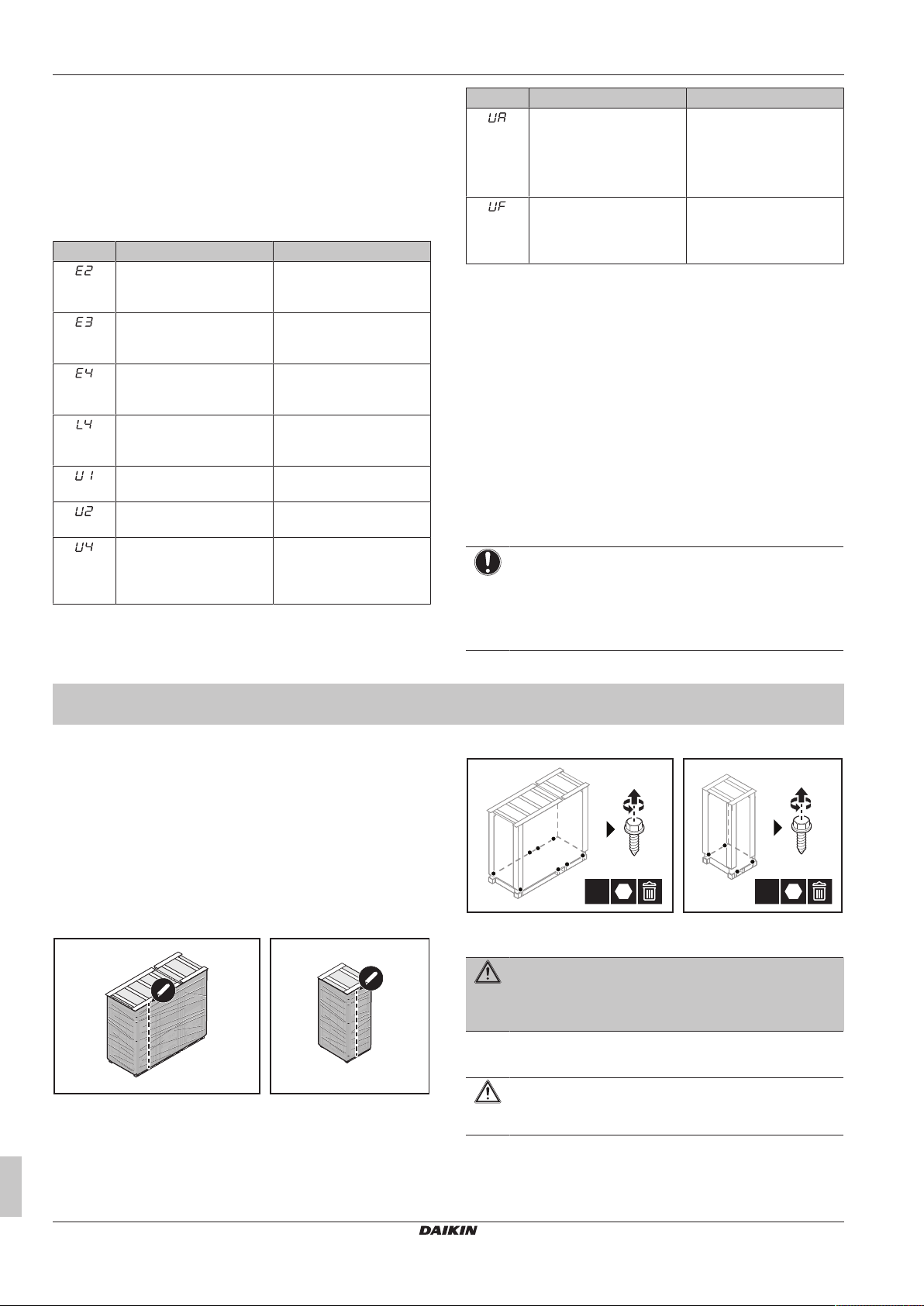
2 The unit is fixed to the pallet with bolts. Remove these bolts.
a Outdoor unit
b Capacity up unit
WARNING
Tear apart and throw away plastic packaging bags so that
nobody, especially children, can play with them. Possible
risk: suffocation.
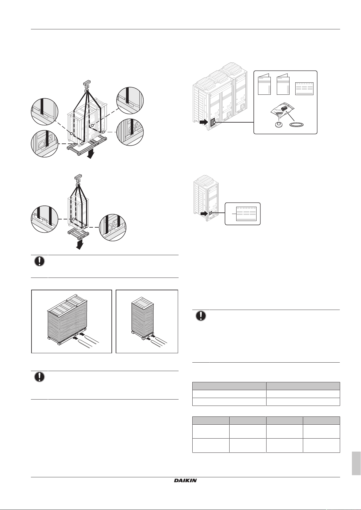
10.1.2 To handle the outdoor unit
CAUTION
To avoid injury, do NOT touch the air inlet or aluminium
fins of the unit.
Installation and operation manual
10
CO₂ Conveni-Pack outdoor unit and capacity up unit
LRYEN10A7Y1+LRNUN5A7Y1
4P605461-1B – 2020.08
11 About the units and options
a b
d e
a b
c
a
Crane
Lift the outdoor unit preferably with a crane and 2 belts of at least
8 m long as shown in the figure below. Always use protectors to
prevent belt damage and pay attention to the centre of gravity of the
unit.
Outdoor unit
Capacity up unit
10.1.3 To remove the accessories from the outdoor unit
Outdoor unit
a General safety precautions
b Operation and installation manual
c Declaration of conformity
d Copper packings for stop valve caps (15×)
e Copper packings for service port caps (15×)
Capacity up unit
NOTICE
Use a belt sling of ≤20mm wide that adequately bears the
weight of the unit.
Forklift
a Outdoor unit
b Capacity up unit
NOTICE
Use filler cloth on the forklift arms to prevent damage to the
unit. Damage to the painting of the unit decreases the anticorrosion protection.
a Declaration of conformity
11 About the units and options
11.1 About the outdoor unit
This installation manual concerns the outdoor unit and the optional
capacity up unit.
These units are intended for outdoor installation and aimed for air to
air heating, cooling and refrigeration applications.
NOTICE
These units (LRYEN10* and LRNUN5*) are only parts of
an air conditioner system, complying with partial unit
requirements of the International Standard IEC
60335-2-40:2018. As such, they must ONLY be connected
to other units that have been confirmed as complying to
corresponding partial unit requirements of this International
Standard.
General name and product name
In this manual, we use the following names:
General name Product name
Outdoor unit LRYEN10A7Y1
Capacity up unit LRNUN5A7Y1
LRYEN10A7Y1+LRNUN5A7Y1
CO₂ Conveni-Pack outdoor unit and capacity up unit
4P605461-1B – 2020.08
Temperature range
Refrigeration A/C cooling A/C heating
Outdoor
temperature
Indoor
temperature
–20~43°CDB –5~43°CDB –20~16°CWB
— 14~24°CWB 15~27°CDB
Installation and operation manual
11
11 About the units and options
WARNING
Unit is charged and under high pressure.
Set pressure of safety valve is 86 bar g.
If refrigerant temperature is higher than 31°C
there is a possibility that the safety valve will
open during service or power shutdown.
WARNING
Unit is charged and under high pressure.
MAXIMUM STORAGE TEMPERATURE
55°C
ab
e e
d c
f
h
i
j
k
h
l
i
j
k
l
g
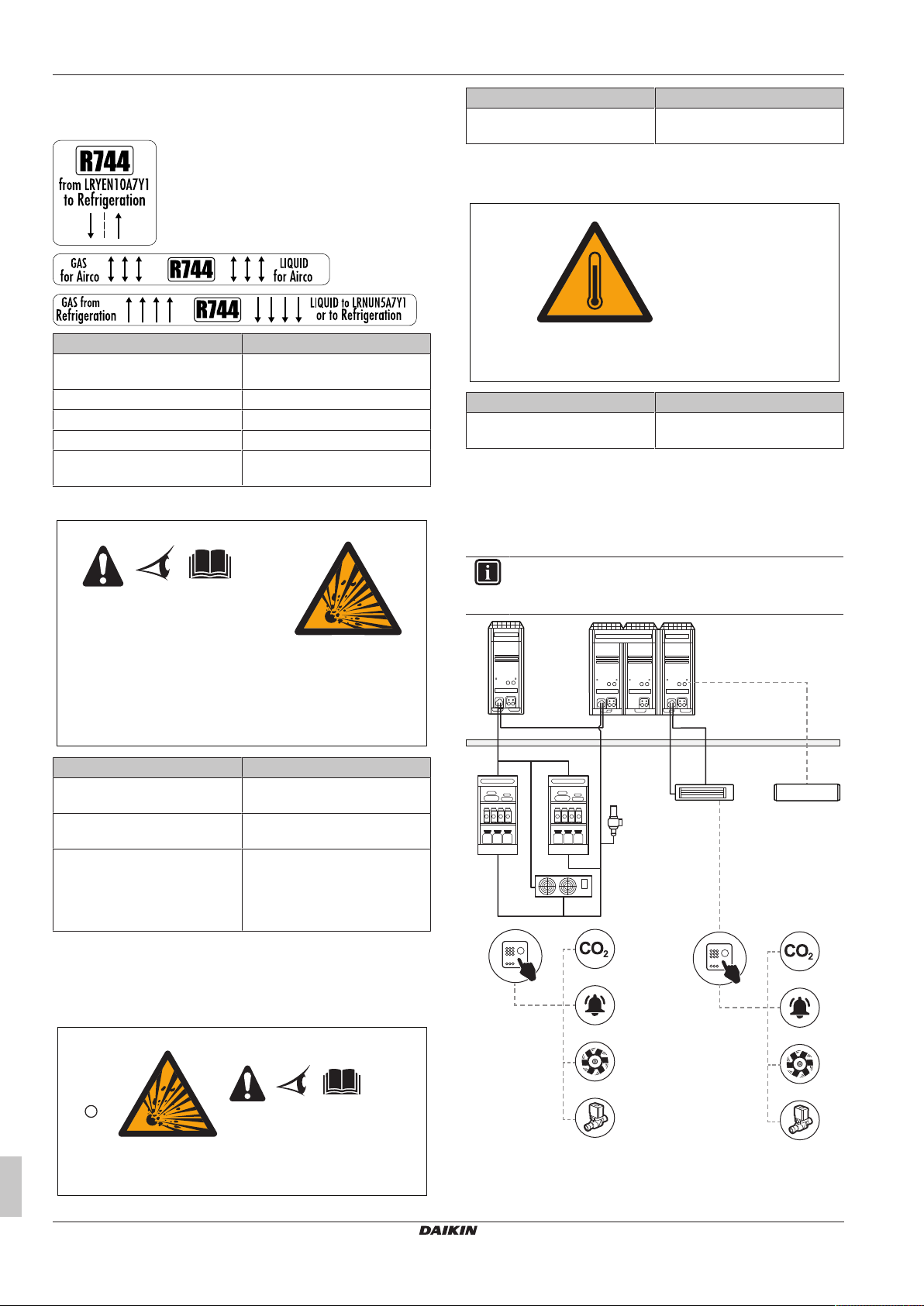
11.1.1 Labels on outdoor unit
Label about flow directions
Text on caution label Translation
from LRYEN10A7Y1 to
Refrigeration
Gas for Airco Gas for Airco
Liquid for Airco Liquid for Airco
Gas from Refrigeration Gas from Refrigeration
Liquid to LRNUN5A7Y1 or to
Refrigeration
Label about safety valve
from LRYEN10A7Y1 to
Refrigeration
Liquid to LRNUN5A7Y1 or to
Refrigeration
Text on warning card Translation
Unit is charged and under high
pressure.
Also see "13.2Using stop valves and service ports"[420].
Label about maximum storage temperature
Text on warning label Translation
MAXIMUM STORAGE
TEMPERATURE: 55°C
The unit is factory charged with refrigerant. To avoid the safety relief
valve being opened, the unit must not be exposed to temperatures
above 55°C.
Unit is charged and under high
pressure.
MAXIMUM STORAGE
TEMPERATURE: 55°C
11.2 System layout
Text on warning label Translation
Unit is charged and under high
pressure.
Set pressure of safety valve is 86
bar g.
If refrigerant temperature is
higher than 31°C there is a
possibility that the safety valve
will open during service or power
shutdown.
Check the set pressure of the safety valve at the low pressure side
of the refrigeration cabinet to verify a safe service temperature.
Also see "13.3.5Guidelines to install safety valves"[423].
Card about stop valves and service ports
INFORMATION
The following illustration is an example and might NOT
match your system layout.
Unit is charged and under high
pressure.
Set pressure of safety valve is
86barg.
If refrigerant temperature is
higher than 31°C there is a
possibility that the safety valve
will open during service or power
shutdown.
Installation and operation manual
12
a Main outdoor unit (LRYEN10*)
b Capacity up unit (LRNUN5*)
c Communication box (BRR9B1V1)
d Fan (indoor unit for air conditioning)
e Showcase (indoor unit for refrigeration)
LRYEN10A7Y1+LRNUN5A7Y1
CO₂ Conveni-Pack outdoor unit and capacity up unit
4P605461-1B – 2020.08
12 Unit installation
f Blower coil (indoor unit for refrigeration)
g Safety valve
h CO2 control panel
i CO2 detector
j CO2 alarm
k CO2 ventilator
l Shut off valve
11.3 Indoor unit constraints
NOTICE
The design pressure of high pressure side of the
connected refrigeration parts MUST be 9MPa (90bar).
NOTICE
If the design pressure of the lower pressure side of
refrigeration parts is different from 90 bar (for example:
60 bar), a safety valve MUST be installed on the field
piping according to this design pressure. It is NOT possible
to connect refrigeration parts with design pressure below
60bar.
NOTICE
The design pressure of the connected air conditioning
parts MUST be 12MPa (120bar). If this is not the case,
please contact your dealer for assistance.
WARNING
Only the refrigeration parts that are also designed to work
with CO2 shall be connected to the system.
Individual control with a remote controller
In case of a system with several air conditioners that are controlled
with the same remote controller in the same space:
Capacity class Individual control with a
remote controller
50 NOT allowed
71+112 Allowed
Restrictions
Keep the following restrictions in mind when you connect indoor
units:
Restriction Minimum/maximum
Minimum air conditioning total
capacity class
Maximum air conditioning total
capacity class
Maximum indoor units that can
be connected
For more information about the possible combinations, see the
installer and user reference guide of the outdoor unit.
162
233
≤4
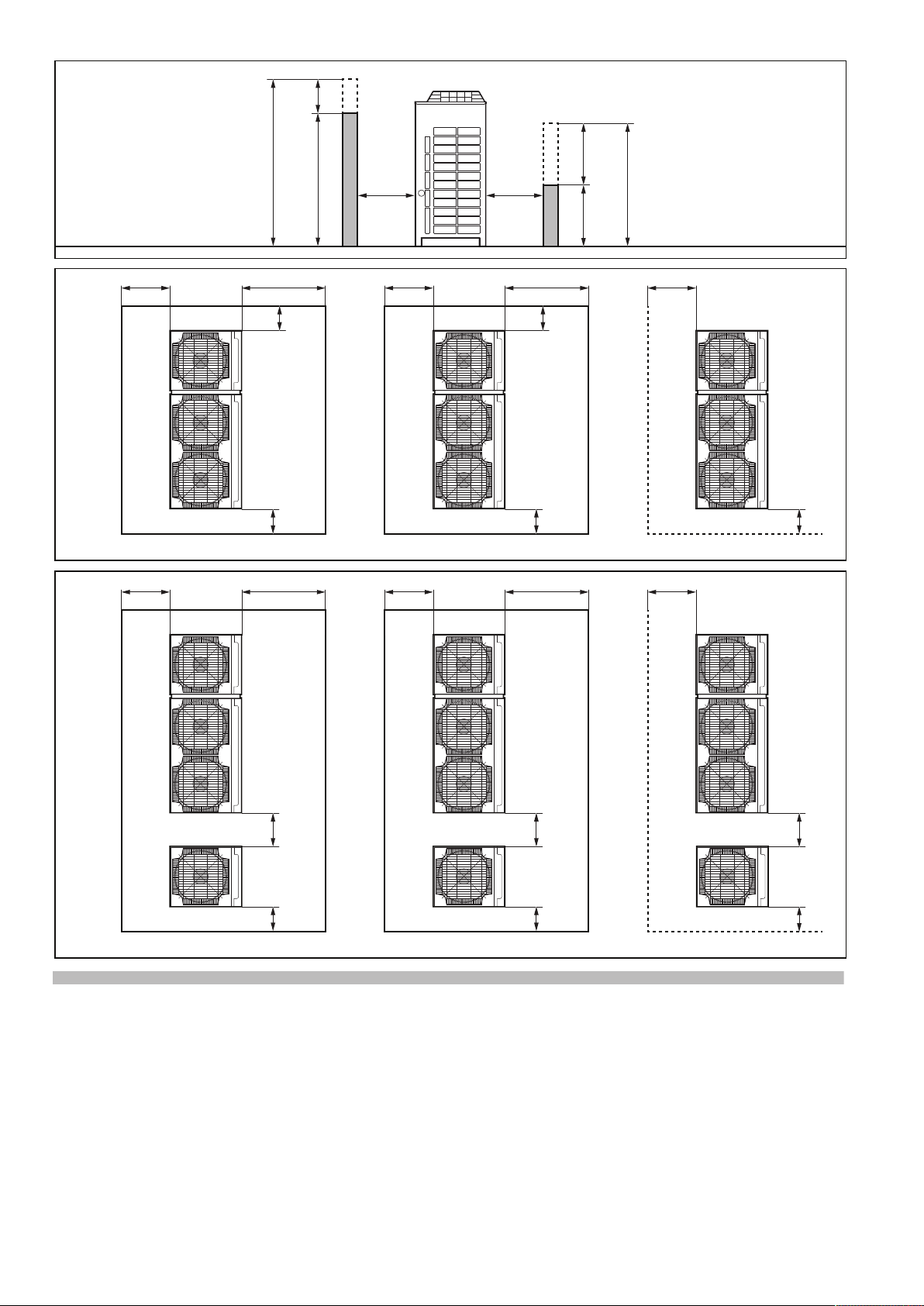
Item Description
B Possible patterns with installation
spaces in case of a single
outdoor unit
(a)(b)(c)(d)
C Possible patterns with installation
spaces in case of an outdoor unit
connected to a capacity up unit
(b)(c)(d)
(a)
h1 H1 (actual height)–1500mm
h2 H2 (actual height)–500mm
X Front side = 500mm+≥h1/2
Y (for patterns B) Air inlet side = 300mm+≥h2/2
Y (for patterns C) Air inlet side = 100mm+≥h2/2
(a)
Wall height front side: ≤1500mm.
(b)
Wall height air inlet side: ≤500mm.
(c)
Wall height other sides: no limit.
(d)
Calculate h1 and h2 as shown in the figure. Add h1/2 for
maintenance space to the front side. Add h2/2 for maintenance
space to the back side (if wall height exceeds above values).
CAUTION
Appliance not accessible to the general public, install it in a
secured area, protected from easy access.
This unit, both indoor and outdoor, is suitable for
installation in a commercial and light industrial
environment.
NOTICE
This is a class A product. In a domestic environment this
product may cause radio interference in which case the
user may be required to take adequate measures.
12.1.2 Additional installation site requirements of the outdoor unit in cold climates
In heavy snowfall areas it is very important to select an installation
site where the snow will NOT affect the unit. If lateral snowfall is
possible, make sure that the heat exchanger coil is NOT affected by
the snow. If necessary, install a snow cover or shed and a pedestal.
INFORMATION
For instructions on how to install the snow cover, contact
your dealer.
12.1.3 Additional installation site requirements for CO₂ refrigerant
NOTICE
Although it is recommended to install LRYEN10* and
LRNUN5* outdoors, in some cases it might be needed to
install them inside. In such cases, ALWAYS follow the
indoor installation site requirements for CO2 refrigerant.
12 Unit installation
12.1 Preparing the installation site
12.1.1 Installation site requirements of the outdoor unit
Mind the spacing guidelines. See figure 1 on the inside of the front
cover.
Description of text on figure 1:
Item Description
A Maintenance space
LRYEN10A7Y1+LRNUN5A7Y1
CO₂ Conveni-Pack outdoor unit and capacity up unit
4P605461-1B – 2020.08
WARNING
In case of mechanical ventilation, take care the ventilated
air is exhausted to the outdoor space and not into another
closed area.
Refrigerant basic characteristics
Refrigerant R744
RCL (refrigerant concentration limit) 0.072kg/m
QLMV (quantity limit with minimum ventilation) 0.074kg/m
QLAV (quantity limit with additional ventilation) 0.18kg/m
Toxicity limit 0.1kg/m
3
Safety class A1
Installation and operation manual
3
3
3
13
12 Unit installation
A (kg)
B (m³)
0
0
100 15050 200 250 300 350 450 550400 500 600 650 700 750 800 850 900 950 1000
5
10
15
20
25
30
35
40
45
50
55
60
65
70
c
b
a
QLMVQLAV
A (kg)
B (m³)
0
0
100 15050 200 250 300 350 450 550400 500 600 650 700 750 800 850 900 950 1000
5
10
15
20
25
30
35
40
45
50
55
60
65
70
dba
RCLQLAV
QLMV
c
INFORMATION
For more information regarding allowable refrigerant
charge and space volume calculations see the reference
guide of the indoor unit.
Appropriate measures
INFORMATION
Appropriate measures are field supply. Choose and install
all required appropriate measures in accordance with
EN378-3:2016.
▪ (natural or mechanical) ventilation
▪ safety shut-off valves
▪ safety alarm, in combination with a CO2 refrigerant leak detector (a
safety alarm alone is NOT considered an appropriate measure
where occupants are restricted in their movements)
▪ CO2 refrigerant leak detector
WARNING
Install the unit only in locations where the doors of the
occupied space are not tight fitting.
WARNING
When using safety shut-off valves, make sure to install
measures such as a bypassing piping with a pressure relief
valve (from liquid pipe to gas pipe). When the safety shutoff valves close and no measures are installed, increased
pressure may damage the liquid piping.
A Refrigerant charge
B Room volume
a 2 appropriate measures required
b 1 appropriate measure required
c No measure required
For occupancies on the lowest underground floor of the
building
If the total refrigerant charge
(kg) divided by the room
(a)
volume
(m3) is…
…the number of appropriate
measures must be at least…
<RCL 0
>RCL and ≤QLMV 1
>QLMV and <QLAV 2
>QLAV Value CANNOT be exceeded!
(a)
For occupied spaces with a floor area exceeding 250m2, use
250m2 as the floor area for determination of the room volume
(Example: even if the room area is 300m2 and the room height
is 2.5m, calculate the room volume as 250m2×2.5m=625m3)
Example: Total refrigerant change in the system is 45kg and room
volume is 300m3. 45/300=0.15, which is >RCL (0.072) and <QLAV
(0.18), therefore install at least 2 appropriate measures in the room.
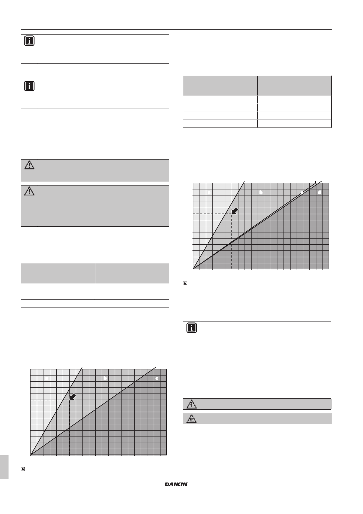
To determine the minimum number of appropriate measures
For occupancies other than on the lowest underground floor of
the building
If the total refrigerant charge
(kg) divided by the room
(a)
volume
(m3) is…
<QLMV 0
>QLMV and <QLAV 1
>QLAV 2
(a)
For occupied spaces with a floor area exceeding 250m2, use
250m2 as the floor area for determination of the room volume
(Example: even if the room area is 300m2 and the room height
is 2.5m, calculate the room volume as 250m2×2.5m=625m3)
Example: Total refrigerant charge in the system is 45 kg and room
volume is 300 m3. 45/300=0.15, which is >QLMV (0.074) and
<QLAV (0.18), therefore install at least 1 appropriate measure in the
room.
…the number of appropriate
measures must be at least…
12‒2 Example graph for calculation
A Refrigerant charge limit
B Room volume
a Installation is not allowed
b 2 appropriate measures required
c 1 appropriate measure required
d No measure required
INFORMATION
Even if there is no refrigerating system on the lowest floor,
where the largest system charge (kg) in the building
divided by total volume of the lowest floor (m3) exceed the
value for QLMV, provide a mechanical ventilation in
accordance with EN 378-3:2016.
12.2 Opening and closing the unit
12.2.1 To open the outdoor unit
DANGER: RISK OF ELECTROCUTION
12‒1 Example graph for calculation
Installation and operation manual
14
DANGER: RISK OF BURNING/SCALDING
To gain access to the unit, front plates need to be opened as follows:
1 Remove the screws of the small front plates.
CO₂ Conveni-Pack outdoor unit and capacity up unit
LRYEN10A7Y1+LRNUN5A7Y1
4P605461-1B – 2020.08

a b
7×
2×
a Outdoor unit
a b
4×
12
×
1
2
4
3
2×
1×
1
2
1×
b
a a
12
×
4×
1
2
4
3
2×
1×
a a
2
1
2×
b
b Capacity up unit
2 Remove the front panels.
12 Unit installation
12.2.2 To open the electrical component box of the outdoor unit
NOTICE
Do NOT apply excessive force when opening the
electronic component box cover. Excessive force can
deform the cover, resulting in entering of water to cause
equipment failure.
Electrical component boxes of the outdoor unit
The electrical component boxes behind the left, middle and right
front panel are all opened in the same way. The main switchbox is
installed behind the middle panel.
Electrical component box of the capacity up unit
a Outdoor unit
b Capacity up unit
3 Remove the small front plates.
a Outdoor unit
b Capacity up unit
Once the front plates open, the electrical component box can be
accessed. See "12.2.2To open the electrical component box of the
outdoor unit"[415].
For service purposes, the pushbuttons on the main PCB (located
behind the middle front panel) need to be accessed. To access
these pushbuttons, the electrical component box cover does not
need to be opened. See "16.1.2 To access the field setting
components"[433].
12.2.3 To close the outdoor unit
NOTICE
When closing the outdoor unit cover, make sure that the
tightening torque does NOT exceed 4.1N•m.
1 Reinstall the small front plates.
LRYEN10A7Y1+LRNUN5A7Y1
CO₂ Conveni-Pack outdoor unit and capacity up unit
4P605461-1B – 2020.08
Installation and operation manual
15

12 Unit installation
a b
12×12
×
4×
a b
2×
7×
631
729
765
≥765
BC
A
497
A
B
631
729
765
≥765
(mm)
1 2
a Outdoor unit
b Capacity up unit
2 Reinstall the front panels.
a Outdoor unit
b Capacity up unit
3 Attach the small front plates to the front panels.
Outdoor unit
a Outdoor unit
b Capacity up unit
12.3 Mounting the outdoor unit
12.3.1 To provide the installation structure
Make sure the unit is installed level on a sufficiently strong base to
prevent vibration and noise.
NOTICE
▪ When the installation height of the unit needs to be
increased, do NOT use stands to only support the
corners.
▪ Stands under the unit must be at least 100mm wide.
NOTICE
The height of the foundation must at least be 150mm from
the floor. In heavy snowfall areas, this height should be
increased up to the average expected snow level,
depending on the installation place and condition.
Capacity up unit
▪ The preferred installation is on a solid longitudinal foundation
(steel beam frame or concrete). The foundation must be larger
than the grey marked area.
Installation and operation manual
16
Minimum foundation
1 LRYEN10*
2 LRNUN5*
Unit A B C
LRYEN10* 1940 1102 193
LRNUN5* 635 497 —
CO₂ Conveni-Pack outdoor unit and capacity up unit
LRYEN10A7Y1+LRNUN5A7Y1
4P605461-1B – 2020.08

▪ Fasten the unit in place using four foundation bolts M12. It is best
20 mm
a
a
b
8×8×
a b
t
Ø
to screw in the foundation bolts until their length remains 20mm
above the foundation surface.
NOTICE
▪ Prepare a water drainage channel around the
foundation to drain waste water from around the unit.
When the outdoor temperatures are negative, the
drained water from the outdoor unit will freeze up. If the
water drainage is not taken care of, the area around
the unit might be very slippery.
▪ When installed in a corrosive environment, use a nut
with plastic washer (a) to protect the nut tightening part
from rust.
13 Piping installation
a LRYEN10*
b LRNUN5*
3 If transported by crane, remove the slings.
12.3.3 To provide drainage
Make sure that condensation water can be evacuated properly.
13 Piping installation
13.1 Preparing refrigerant piping
12.3.2 To install the outdoor unit
1 Transport the unit by crane or forklift and put it onto the
installation structure.
2 Fix the unit to the installation structure.
a LRYEN10*
b LRNUN5*
13.1.1 Refrigerant piping requirements
WARNING
The unit is partially factory charged with refrigerant R744.
NOTICE
Refrigerant R744 requires strict cautions for keeping the
system clean and dry. Foreign materials (including mineral
oils or moisture) should be prevented from getting mixed
into the system.
NOTICE
The piping and other pressure-containing parts shall be
suitable for refrigerant and oil. Use K65 copper-iron alloy
tube system for high-pressure applications with a working
pressure of 120 bar at the air conditioner side and 90 bar
at the refrigeration side.
NOTICE
Do not use standard hoses and manometers. Use ONLY
equipment that is designed to use with R744.
▪ Foreign materials inside pipes (including oils for fabrication) must
be ≤30mg/10m.
13.1.2 Refrigerant piping material
▪ Piping temper grade and thickness:
Piping refrigeration unit
Piping type Outer
diameter
Liquid piping 12.7mm
Gas piping 15.9mm
(a)
Depending on the applicable legislation and the maximum
working pressure of the unit (see "PS High" on the unit name
plate), larger piping thickness might be required.
Piping air conditioning unit
(Ø)
(1/2")
(5/8")
Temper
grade
R420
(with heat
treatment)
R300
(drawn)
Thickness
(a)
(t)
≥0.85mm
≥1.05mm
LRYEN10A7Y1+LRNUN5A7Y1
CO₂ Conveni-Pack outdoor unit and capacity up unit
4P605461-1B – 2020.08
Installation and operation manual
17

13 Piping installation
t
Ø
a
c
b
a
b
a
b
a
b
Piping type Outer
diameter
Temper
grade
Thickness
(a)
(t)
(Ø)
Liquid piping 15.9mm
(5/8")
Gas piping 19.1mm
(3/4")
(a)
Depending on the applicable legislation and the maximum
working pressure of the unit (see "PS High" on the unit name
plate), larger piping thickness might be required.
R300
(drawn)
R300
(drawn)
≥1.05mm
≥1.30mm
13.1.3 Refrigerant piping length and height difference
Requirements and limits
The piping lengths and height differences must comply with the
following requirements. For an example, see "13.1.4 To select the
piping size"[418].
Requirement Limit
LRYEN10* LRYEN10* +
LRNUN5*
Maximum total piping length
Examples:
(a)
≤Limit
(a)
(a)
(a)
≤Limit
≤Limit
≤Limit
▪ A+B+C+D+(E or F)
▪ a+c+d+(e or f)
▪ A2+B2+(C2 or D2)
▪ a2+b2+(c2 or d2)
Piping length between
LRYEN10* and LRNUN5*
Maximum actual piping length
▪ Example refrigeration side:
▪ C+D+(E or F)
▪ c+d+(e or f)
(a)
(a)
▪ c+g
▪ j
▪ Example air conditioner side:
▪ B2+(C2 or D2)
▪ b2+(c2 or d2)
Maximum
height
difference
between
outdoor unit
and indoor
unit
(a)
(a)
Outdoor higher
than indoor
Example: H2,
H4≤Limit
Outdoor unit
lower than
indoor unit
Example: H2,
H4≤Limit
Maximum height difference
between blower coil and
showcase
▪ Example: H3≤Limit
Refrigeration side: 130m
Air conditioning side: 130m
Not specified, but piping must be
horizontal
Refrigeration side: 50m
Air conditioning side: 30m
35m
"To install an oil trap"[418]
10m
"To install riser piping"[418]
5m
Requirement Limit
LRYEN10* LRYEN10* +
LRNUN5*
Maximum height difference
0.5m
between air conditioners
▪ Example: H1≤Limit
(a)
Whichever is longer
To install an oil trap
If the outdoor unit is installed higher than the indoor unit, install an oil
trap in the gas piping every 5meter. Oil traps will make the oil return
more easily.
a Showcase
b Height difference=5m
c Trap
The refrigerant suction piping must always run down:
a Outdoor unit or indoor unit
b Flow direction in refrigerant suction piping
To install riser piping
If the outdoor unit is installed lower than the indoor unit, install the
riser piping close to the indoor unit. When the compressor of the
outdoor unit starts, a correct installed riser piping will prevent liquid
from flowing back to the outdoor unit.
a Outdoor unit
b Indoor unit
13.1.4 To select the piping size
Determine the proper size using the following tables and reference
figure (only for indication).
Installation and operation manual
18
c Riser piping up to indoor unit.
LRYEN10A7Y1+LRNUN5A7Y1
CO₂ Conveni-Pack outdoor unit and capacity up unit
4P605461-1B – 2020.08

2
A A2
B2 C2
B
CD
G
J
j
f
F
E2
D2
E
H4
H3
H1
H1
H2
e d
g
c a b2
a2
e2
d2
c2
1
3
5
4
4
5
5
3
H4
1 Capacity up unit (LRNUN5*)
e
d
b
c
a
2 Outdoor unit (LRYEN10*)
3 Indoor unit (showcase)
4 Indoor unit (blower coil)
5 Indoor unit (air conditioning)
A~J Liquid piping (side showcases and blower coils)
A2~E2 Liquid piping (side air conditioning)
a~g Gas piping (side showcases and blower coils)
a2~e2 Gas piping (side air conditioning)
H1~H4 Height difference
In case the required pipe sizes (inch sizes) are not available, it is
also allowed to use other diameters (mm sizes), taken the following
into account:
▪ Select the pipe size nearest to the required size.
▪ Use the suitable adapters for the change-over from inch to mm
pipes (field supply).
▪ The additional refrigerant calculation has to be adjusted as
mentioned in the following chapters:
▪ For outdoor unit without capacity up unit: "15.2 To determine
additional refrigerant amount"[432].
▪ For outdoor unit with capacity up unit: see "15.2To determine
additional refrigerant amount" [432] but additional refrigerant is
not needed because the capacity up unit is already precharged.
Piping size between outdoor unit and first branch
When the equivalent pipe length between outdoor unit and the
furthest indoor unit is 90m or more (b+d), the size of the main gas
pipe (b) must be increased (size-up). If the recommended gas pipe
(size-up) is not available, you must use the standard size (which
might result in a small capacity decrease).
13 Piping installation
(a)
For refrigeration piping (A, B, a) and for air conditioner piping (A2,
a2)
Piping size between branching areas or between first and second branch
Indoor unit capacity
index (kW)
Refrigeration side: liquid pipe
x≤10.0 Ø9.5×t0.65 (K65)
10.0<x Ø12.7×t0.85 (K65)
Refrigeration side: gas pipe
x≤6.5 Ø9.5×t0.65 (K65)
6.5<x≤14.0 Ø12.7×t0.85 (K65)
14.0<x Ø15.9×t1.05 (K65)
Air conditioner side: liquid pipe
— Ø12.7×t0.85 (K65)
Air conditioner side: gas pipe
— Ø15.9×t1.05 (K65)
(a)
Piping between branching areas (C, D, c, d)
(b)
Piping from first branch to second branch (B2, b2)
Piping outer diameter size (mm)
(a)
(a)
(b)
(b)
a Outdoor unit
b Main gas pipe
c First refrigerant branch
d Piping between indoor unit and refrigerant branch
e Furthest indoor unit
System side Piping outer diameter size
Refrigeration Ø12.7×t0.85
Air conditioner Ø15.9×t1.05
LRYEN10A7Y1+LRNUN5A7Y1
CO₂ Conveni-Pack outdoor unit and capacity up unit
4P605461-1B – 2020.08
(a)
(mm)
Liquid side Gas side
Ø15.9×t1.05
(K65)
(K65)
(K65)
Ø19.1×t1.3
(K65)
Piping size from branch to indoor unit
Same size as C, D, c, d.
If piping sizes of the indoor units are different, connect a reducer
close to the indoor unit to align piping sizes.
Piping outer diameter size (mm)
Gas pipe Liquid pipe
Refrigeration side
Air conditioner side
(a)
(b)
Ø12.7×t0.85 (K65) Ø9.5×t0.65 (K65)
(a)
Piping from branch to indoor unit (E, F, G, J, e, f, g, j)
(b)
Piping from branch to indoor unit (C2, D2, E2; c2; d2; e2)
Installation and operation manual
19

13 Piping installation
2
A
C
A
A
B
C
C
1
5
3
4
A
B B
A
a a
b b
B
1 2 3
Stop valve size
Refrigeration side
Air conditioner
(a)
side
(a)
Reducers (field supply) may be required to connect the piping.
(a)
Liquid side Gas side
Ø15.9 Ø19.1
Ø15.9 Ø15.9
13.1.5 To select refrigerant branch kits
Always use K65 T-joints with a suitable design pressure for
refrigerant branching.
13.1.6 To select expansion valves for refrigeration
The system controls liquid temperature and liquid pressure. Select
the expansion valves as indicated according to nominal conditions
and design pressure.
Nominal conditions
The following nominal conditions are valid for the liquid piping at the
outlet of the outdoor unit. They are based on an ambient
temperature of 32°C and an evaporate temperature of -10°C.
If showcases or blower coils are connected directly
Liquid temperature 23°C
Liquid pressure 6.8MPaG
Refrigerant condition Subcooled liquid
If capacity up unit is connected between outdoor unit and
showcases or blower coils
Liquid temperature (at outlet of capacity up
unit)
Liquid pressure (at outlet of capacity up unit) 6.8MPaG
Refrigerant condition (at outlet of capacity up
unit)
(optional) If a pressure reduction kit is connected between
outdoor unit and showcases or blower coils
Liquid temperature (at outlet of pressure
reduction kit)
Liquid pressure (at outlet of pressure
reduction kit)
Refrigerant condition Subcooled liquid
Design pressure
Make sure all parts comply to the following design pressure:
3°C
Subcooled liquid
3°C
4.8~5.6MPaG
5 Indoor unit (air conditioning)
A Liquid piping (refrigeration side): 90bar
B Gas piping (refrigeration side): depends on design
pressure of showcase and blower coil. For example,
60bar
C Gas and liquid piping (air conditioning side): 120bar
13.2 Using stop valves and service ports
For more information about the card on the unit, see "Card about
stop valves and service ports"[412].
WARNING
When stop valves are closed during service, the pressure
of the closed circuit will increase due to high ambient
temperature. Make sure the pressure is kept below the
design pressure.
13.2.1 To handle the stop valve
Take the following guidelines into account:
▪ Make sure to keep all stop valves open during operation.
▪ The gas and liquid stop valves are factory closed.
▪ Do NOT apply excessive force to the stop valve. Doing so may
break the valve body.
Open versus closed
All stop valves are of the backseat type and do not have a valve core
for the charge port.
A Fully closed (connected between charge port and indoor
unit side)
B Fully open (connected between outdoor unit and indoor
unit)
a To outdoor unit
b To indoor unit
Installation and operation manual
20
1 Capacity up unit (LRNUN5*)
2 Outdoor unit (LRYEN10*)
3 Indoor unit (showcase)
4 Indoor unit (blower coil)
To open the stop valve
1 Remove the valve cap with 2 spanners.
2 Loosen the packing holder by rotating counterclockwise from
1/8 to 1/2 turn.
3 Turn the valve stem counterclockwise until it stops.
To close the stop valve
1 Turn the valve stem clockwise until it stops. Tighten with the
appropriate tightening torque.
LRYEN10A7Y1+LRNUN5A7Y1
CO₂ Conveni-Pack outdoor unit and capacity up unit
4P605461-1B – 2020.08

13 Piping installation
a
b
a
b
c
A B
a
a
b
2 Tighten the packing holder.
3 Before mounting the valve cap, insert a new copper packing.
4 Apply screw lock agent or silicon sealant to the screw thread
when mounting the valve cap. If not, moisture and condensing
water may penetrate and freeze between the screw thread. As
a result, refrigerant may leak and the valve cap may break.
a Apply screw lock agent
b Do NOT apply screw lock agent
5 Tighten the valve cap.
Also see "13.2.3Tightening torques"[421].
To open the service port
1 Remove the service port cap with 2 spanners and remove the
copper packing.
2 Connect the charge port to the service port.
3 Remove the valve cap with 2 spanners.
4 Insert a hexagonal wrench (4mm) and rotate counterclockwise
until it the end.
To close the service port
1 Insert a hexagonal wrench (4mm) and rotate clockwise until the
end.
2 Tighten the valve cap.
3 Remove the copper packing of the service port cap.
13.2.2 To handle the service port
▪ Always use a charge hose equipped with a valve depressor pin,
since the service port is a Schrader type valve.
▪ After handling the service port, make sure to tighten the service
port cover securely. For the tightening torque, refer to the table
below.
▪ Check for refrigerant leaks after tightening the service port cover.
The figure below shows the name of each part required in handling
the stop valve.
a Service port cap
b Copper packing
c Valve cap
Open versus closed
All service ports are of the backseat type and do not have a valve
core.
a Copper packing
4 Add a new copper packing and mount the service port cap.
Apply screw lock agent or silicon sealant to the screw thread
when mounting the service port cap. If not, moisture and
condensing water may penetrate and freeze between the screw
thread. As a result, refrigerant may leak and the valve cap may
break.
a New copper packing
b Screw lock agent or silicon sealant only on screw thread
5 Tighten the service port cap.
Also see "13.2.3Tightening torques"[421].
13.2.3 Tightening torques
Stop valve
size (mm)
LRYEN10A7Y1+LRNUN5A7Y1
CO₂ Conveni-Pack outdoor unit and capacity up unit
4P605461-1B – 2020.08
A Fully closed
B Fully open
Ø15.9 38.2~46.6 7.4~9.0 13.2~16.0 14.2~17.2
Ø19.1
Tightening torque N•m (turn clockwise to close)
Shaft
Valve cap Packing
pressure
Valve stem Valve core
cap
Installation and operation manual
21

13 Piping installation
1 2 3
a
b
c
d
a
b
A
B
a
b
13.3 Connecting the refrigerant piping
DANGER: RISK OF BURNING/SCALDING
13.3.1 To remove the spun pipes
WARNING
Any gas or oil remaining inside the stop valve may blow off
the spun piping.
If these instructions are NOT followed correctly it may
result in property damage or personal injury, which may be
serious depending on the circumstances.
1 Open the stop valve cap, unlock the valve and check if the
valve is closed.
1 Remove the valve cap with 2 spanners
(counterclockwise).
2 Loosen the packing holder by rotating counterclockwise
from 1/8 to 1/2 turn.
3 Close the valve (clockwise).
2 Open the service port cap slowly and check that there is no
pressure left.
3 Incrementally loosen the valve core to ensure that there is no
pressure left.
4 Cut off the lower part of the gas and liquid stop valve pipes
along the black line. Use only appropriate tools, such as a pipe
cutter or pair of nippers.
13.3.2 To connect the refrigerant piping to the outdoor unit
You can route refrigerant piping to the front or side of the unit.
For the outdoor unit:
a Left side connection
b Front connection (refrigeration)
c Front connection (air conditioner)
d Right side connection
For the capacity up unit:
a Left side connection
b Front connection (refrigeration)
NOTICE
Precautions when making knockout holes:
▪ Avoid damaging the casing.
▪ After making the knockout holes, we recommend you
remove the burrs and paint the edges and areas
around the edges using repair paint to prevent rusting.
▪ When passing electrical wiring through the knockout
holes, wrap the wiring with protective tape to prevent
damage.
Front connection
WARNING
1 Remove the knockout and connect the piping to the outdoor
unit.
Never remove the spun piping by brazing.
Any gas or oil remaining inside the stop valve may blow off
the spun piping.
INFORMATION
If the stop valve was initially open, a small amount of
refrigerant or oil may leak out.
5 Wait until all oil has dripped out before continuing with the
connection of the field piping in case the recovery was not
complete.
You can now connect the ingoing and outgoing refrigerant piping.
Installation and operation manual
22
2 If applicable, remove the knockout and connect the piping to the
A Stop valve (gas – refrigeration)
B Stop valve (liquid – refrigeration)
a Gas piping
b Liquid piping
capacity up unit.
LRYEN10A7Y1+LRNUN5A7Y1
CO₂ Conveni-Pack outdoor unit and capacity up unit
4P605461-1B – 2020.08

13 Piping installation
4×
a
b
c
b
a
A
B
a
b
a
b
c
a
b
c
a
a
b
d
Side connection
1 Remove the knockout on the bottom plate.
a Drill (Ø6mm)
b Knockout plate
c Drill here
2 Connect the piping to the outdoor unit.
A Stop valve (gas – refrigeration)
B Stop valve (liquid – refrigeration)
a Gas piping
b Liquid piping
3 If applicable, connect the piping to the capacity up unit.
13.3.3 Guidelines to connect T-joints
INFORMATION
Piping joints and fittings shall comply with the requirements
of EN14276-2.
CAUTION
ALWAYS use K65 T-joints for refrigerant branching.
K65 T-joints are field supplied.
Liquid piping
Always branch horizontally when connecting the branch piping.
To prevent uneven refrigerant flow, always branch downwards when
using a header.
a Coming from the indoor units
b Going to the outdoor units
c Main refrigerant pipe
d Slanting downwards
NOTICE
Where joints are used on piping, avoid damage caused by
freezing or vibration.
13.3.4 Guidelines to install a dryer
NOTICE
Do NOT operate the unit without a dryer installed on the
liquid pipe of the refrigeration side. Possible
consequence: Without dryer, operating the unit may
cause a choked expansion valve, hydrolysis of the
refrigerant oil and copper plating of the compressor.
Install a dryer on the liquid piping of the refrigeration side:
Dryer type Drops of R744 water capacity at 60°C: 200
Recommended dryer for use with transcritical
CO2:
For LRYEN10*: CO-085-S (by Sporlan)
Where/how Install the dryer as near as possible to the
outdoor unit.
(a)
Install the dryer on the liquid pipe of the
refrigeration side.
Install the dryer horizontally.
When brazing Follow the brazing instructions in the dryer
manual.
Remove the dryer cap immediately before
brazing (to prevent absorption of moisture).
If dryer paint burnt during brazing, repair it. For
repair paint details, contact the manufacturer.
Flow direction If the dryer specifies a flow direction, install
accordingly.
(a)
Follow the instructions in the installation manual of the dryer.
13.3.5 Guidelines to install safety valves
When installing a safety valve, always keep the design pressure of
the circuit in mind. See "5.2Design pressure"[48].
NOTICE
The design pressure of high pressure side of the
connected refrigeration parts MUST be 9MPa (90bar).
NOTICE
If the design pressure of the lower pressure side of
refrigeration parts is different from 90 bar (for example:
60 bar), a safety valve MUST be installed on the field
a Coming from the outdoor units
b Going to the indoor units
Gas piping
Always branch horizontally when connecting the branch piping.
piping according to this design pressure. It is NOT possible
to connect refrigeration parts with design pressure below
60bar.
To prevent refrigerant oil flowing into the indoor units, always set the
branch piping above the main piping.
LRYEN10A7Y1+LRNUN5A7Y1
CO₂ Conveni-Pack outdoor unit and capacity up unit
4P605461-1B – 2020.08
Installation and operation manual
23

13 Piping installation
a
N2
R744
a
b
b
b
b
c1 d1
E
C
A
B
D
e
f
c2 d2
NOTICE
The design pressure of the connected air conditioning
parts MUST be 12MPa (120bar). If this is not the case,
please contact your dealer for assistance.
CAUTION
When installing a safety valve, ALWAYS add enough
support to the valve. An activated safety valve is under
high pressure. If not installed securely, the safety valve
may cause damage to the piping or the unit.
13.4 Checking the refrigerant piping
Keep the following in mind:
▪ Refrigerant R744 is precharged into the unit.
▪ Always keep both liquid and gas stop valves closed during leak
test and vacuum drying of the field piping.
▪ If installed, see the installation manual of the pressure reduction
kit.
▪ Only use R744 dedicated tools (such as gauge manifold and
charge hose) that are designed to withstand high pressures and
which will prevent water, dirt or dust entering the unit.
CAUTION
Do NOT open the stop valve until you have measured the
insulation resistance of the main power supply circuit.
CAUTION
ALWAYS use nitrogen gas for leak tests.
13.4.1 Checking refrigerant piping: Setup
A Nitrogen (N2)
B R744 refrigerant tank
C Weighing scales
D Vacuum pump
E Outdoor unit
a Pressure regulator
b Charge hose
c1, c2 Gas side
d1, d2 Liquid side
e To refrigeration indoor unit
f To air conditioning indoor unit
Stop valve
Service port
Field piping
Installation and operation manual
24
NOTICE
The connections to the indoor units and all indoor units
should also be leak and vacuum tested. Keep any possible
(field supplied) field piping valves open as well.
Also see the indoor unit installation manual for more
details. Leak test and vacuum drying should be done
before the power supply is set to the unit.
13.4.2 To perform a leak test
The leak test must satisfy the specifications of EN378‑2.
1 Connect to the gas side (c) and liquid side (d) of the circuit you
want to test. See "13.4.1 Checking refrigerant piping:
Setup"[424].
2 Pressurize both liquid side and gas side of the refrigeration
circuit up to 3.0MPa (30 bar) from the charge port of the stop
valve.
3 Pressurize both liquid side and gas side of the air conditioner
circuit up to 3.0MPa (30 bar) from the charge port of the stop
valve.
4 Make sure there is no pressure drop for at least 24 hours.
5 If there is a pressure drop, locate the leak and repair.
13.4.3 To perform vacuum drying
1 Connect a vacuum pump to the charge ports of the gas stop
valves (c) and liquid stop valves (d). See "13.4.1 Checking
refrigerant piping: Setup"[424].
2 Vacuum the unit for at least 2hours and to –0.1MPa or below.
3 Leave the unit for more than 1 hour with a vacuum pressure of
–0.1MPa or less. On the vacuum gauge, check if the pressure
does not increase. If the pressure rises, the system has a leak
or moisture remained into the piping.
In case of a leak
1 Find and repair the leak.
2 When done, vacuum again according to the procedure above.
In case of remaining moisture
When the unit is installed on rainy days, moisture may still remain in
the piping after a first vacuum drying is performed. If so, conduct the
following procedure:
1 Pressurize the nitrogen gas up to 0.05 MPa (for vacuum
destruction) and vacuum for at least 2hours.
2 Afterwards, vacuum dry the unit to –0.1MPa or less for at least
1hour.
3 Repeat vacuum destruction and vacuum drying if the pressure
does not reach –0.1MPa or less.
4 Leave the unit for more than 1 hour with a vacuum pressure of
–0.1MPa or less. On the vacuum gauge, check if the pressure
does not increase.
13.5 Insulating the refrigerant piping
After finishing the leak test and vacuum drying, the piping must be
insulated. Take into account the following points:
▪ Be sure to insulate the liquid and gas piping (for all units).
▪ Use heat resistant polyethylene foam which can withstand a
temperature of 70°C for:
▪ all liquid piping at both the air conditioner and the refrigeration
side.
▪ gas piping at the refrigeration side.
▪ Use heat resistant polyethylene foam which can withstand a
temperature of 120°C for gas piping at the air conditioner side.
LRYEN10A7Y1+LRNUN5A7Y1
CO₂ Conveni-Pack outdoor unit and capacity up unit
4P605461-1B – 2020.08

14 Electrical installation
a
a
a
a
b
b
Insulation thickness
Take the following into account when determining the insulation
thickness:
Piping Mode Minimum
temperature during
operation
Liquid piping Refrigeration 0°C
Air conditioner 20°C
Gas piping Refrigeration –20°C
Air conditioner 0°C
Depending on your local weather conditions, you may need to
increase the thickness of the insulation. If the ambient temperature
exceeds 30°C and the humidity exceeds 80%.
▪ Increase the thickness of the liquid piping with ≥5mm.
▪ Increase the thickness of the gas piping with ≥20mm.
Insulation sealing
To prevent rain and condensed water entering the unit, add a
sealing between the insulation and the front panel of the unit.
▪ EN/IEC 61000‑3‑12 provided that the short-circuit power Ssc is
greater than or equal to the minimum Ssc value at the interface
point between the user's supply and the public system.
▪ EN/IEC 61000‑3‑12 = European/International Technical
Standard setting the limits for harmonic currents produced by
equipment connected to public low-voltage systems with input
current >16A and ≤75A per phase.
▪ It is the responsibility of the installer or user of the equipment to
ensure, by consultation with the distribution network operator if
necessary, that the equipment is connected only to a supply
with a short-circuit power Ssc greater than or equal to the
minimum Ssc value.
Model Z
max
Minimum S
sc
value
LRYEN10A7Y1 — 4337
LRNUN5A7Y1 — 2294
a Sealing material
b Front panel
14 Electrical installation
DANGER: RISK OF ELECTROCUTION
WARNING
ALWAYS use multicore cable for power supply cables.
NOTICE
The distance between the high voltage and low voltage
cables should be at least 50mm.
14.1 About electrical compliance
This equipment (LRYEN10A7Y1 and LRNUN5A7Y1) complies with:
▪ EN/IEC 61000‑3‑11 provided that the system impedance Z
less than or equal to Z
at the interface point between the user's
max
supply and the public system.
▪ EN/IEC 61000‑3‑11 = European/International Technical
Standard setting the limits for voltage changes, voltage
fluctuations and flicker in public low-voltage supply systems for
equipment with rated current ≤75A.
▪ It is the responsibility of the installer or user of the equipment to
ensure, by consultation with the distribution network operator if
necessary, that the equipment is connected only to a supply
with a system impedance Z
less than or equal to Z
sys
max
sys
.
is
LRYEN10A7Y1+LRNUN5A7Y1
CO₂ Conveni-Pack outdoor unit and capacity up unit
4P605461-1B – 2020.08
Installation and operation manual
25

14 Electrical installation
g
F2F1 F1
X1M (A1P)
F2 Q1 Q2
TO
MULTI UNIT
TO
OUT/D UNIT
TO
IN/D UNIT
L1 L2 L3 N
X1M PE X2M
C C1 W1 R P1 P2
21 3
X3M
L N
X2M
P1 P2 F1 F2 T1 T2
F2F1 F1
X1M (A1P)
F2 Q1 Q2
TO
MULTI UNIT
TO
OUT/D UNIT
TO
IN/D UNIT
L1 L2 L3 N
X1M PEX4M
C C1 W1 R P1 P2
21 3
X5M
L N
X2M
X1M
X1M
P1 P2 F1 F2 T1 T2
P1 P2
L N
X1M PEX3M
A+ B- F1 F2
220-240 V AC
220-240 V AC
220-240 V AC
12 V DC
12 V DC
12 V DC
12 V DC
220-240 V AC
220-240 V AC
220-240 V AC
220-240 V AC
1N~ 50 Hz
220-240 V AC
RS-485
DIII
DIII
DIII
DIII
DIII
f gf
d
ed e
a
i
i
b
d1 d2
h
h1 h2
d1 d2
X1M (A1P)
X5M
X4M
X1M
PE
X1M
X3M
PE
X1M (A1P)
X2M
X1M
X3M
PE
k1
k
l
m
k2
k4
k3
j
3N~ 50 Hz
380-415 V AC
c1
c2
3N~ 50 Hz
380-415 V AC
c1
c2
c1
c2
1N~ 50 Hz
220-240 V AC
c1
c2
k5
R1
R1
RS-485
DIII
R1
14.2 Field wiring: Overview
INFORMATION
Indoor units (air conditioning). This field wiring overview
shows only one possible wiring for the indoor units (air
conditioning). For more possibilities, see the indoor unit
manual.
a Capacity up unit (LRNUN5A7Y1) i Indoor unit (air conditioning)
b Outdoor unit (LRYEN10A7Y1) j User interface for indoor units (air conditioning)
c1 Overcurrent fuse (field supply) k Safety system (field supply). Example:
c2 Earth leakage circuit breaker (field supply) k1: Control panel
d Alarm panel (field supply) for: k2: CO2 refrigerant leak detector
d1: Caution output signal k3: Safety alarm (lamp)
d2: Warning output signal k4: Ventilation (natural or mechanical)
e Control panel (field supply) for operation output signal k5: Shut off valve
f Remote operation switch (field supply) l Communication box (BRR9B1V1)
g Remote low noise switch (field supply) m Monitoring system (field supply)
OFF: normal mode
ON: low noise mode
h Operation output signal to expansion valves of all:
h1: Blower coils (field supply)
h2: Showcases (field supply)
Wiring:
RS-485 transmission wiring (mind polarity)
DIII transmission wiring (no polarity)
Operation output
Installation and operation manual
26
LRYEN10A7Y1+LRNUN5A7Y1
CO₂ Conveni-Pack outdoor unit and capacity up unit
4P605461-1B – 2020.08

14 Electrical installation
a
b
g
d dc f c ee
X1M (A1P)
a b
X5M
X4M
X1M
PE
X1M (A1P)
X2M
X1M
X3M
PE
14.3 Guidelines when knocking out knockout holes
▪ To punch a knockout hole in a front panel, hit on it with a hammer.
▪ To punch a knockout hole in the bottom panel, drill holes where
indicated.
▪ After knocking out the holes, we recommend removing any burrs
and paint the edges and areas around the holes using repair paint
to prevent rusting.
▪ When passing electrical wiring through the knockout holes.
prevent damage to the wires by wrapping the wiring with
protective tape, putting the wires through field supplied protective
wire conduits at that location, or install suitable field supplied wire
nipples or rubber bushings into the knockout holes.
14.4 Guidelines when connecting the electrical wiring
Tightening torques
a Terminals on outdoor unit
b Terminals on capacity up unit
Terminal Screw size Tightening torque
(N•m)
X1M: Power supply M8 5.5~7.3
PE: Protective earth
(screw)
X2M, X4M: Output
signals
X3M, X5M: Remote
switches
X1M (A1P): DIII
transmission wiring
M8
M4 1.18~1.44
M3.5 0.79~0.97
M3.5 0.80~0.96
a Outdoor unit
b Capacity up unit
Knockout holes for:
c Piping (refrigeration)
d High voltage wiring
e Low voltage wiring
f Piping (air conditioning)
g Remove burrs
WARNING
Provide adequate measures to prevent that the unit can be
used as a shelter by small animals. Small animals that
make contact with electrical parts can cause malfunctions,
smoke or fire.
14.5 Specifications of standard wiring components
Power supply
NOTICE
When using residual current operated circuit breakers, be
sure to use a high-speed type 300 mA rated residual
operating current.
The power supply must be protected with the required safety
devices, i.e. a main switch, a slow blow fuse on each phase and an
earth leakage protector in accordance with the applicable legislation.
Selection and sizing of the wiring should be done in accordance with
the applicable legislation based on the information mentioned in the
table below.
Make sure that a separate power supply circuit is provided for this
unit and that all electrical work is carried out by qualified personnel
according to local laws and regulations and this manual. An
insufficient power supply capacity or improper electrical construction
may lead to electric shocks or fire.
Model Minimum
circuit ampacity
LRYEN10A7Y1 33A 45A 3N~ 50Hz
LRNUN5A7Y1 16A 25A 3N~ 50Hz
Recommended
fuses
Power supply
380-415V
380-415V
LRYEN10A7Y1+LRNUN5A7Y1
CO₂ Conveni-Pack outdoor unit and capacity up unit
4P605461-1B – 2020.08
DIII transmission wiring
Transmission wiring specification and limits
Vinyl cords with 0.75 to 1.25mm² sheath or cables (2‑core wires)
Installation and operation manual
(a)
27

14 Electrical installation
b
F2F1 F1
X1M (A1P)
ca
F2 Q1 Q2
TO
MULTI UNIT
TO
OUT/D UNIT
TO
IN/D UNIT
d e
21 3
X5M
a/b/cd/e
X1M (A1P)
X5M
1
2
X1M (A1P)
X5M
1
2
f
REMOTE
OFF
ON
S1S
(a)
If the total transmission wiring exceeds these limits,
communication errors might occur.
Remote switches
See details in:
▪ "14.6.1Low voltage wiring – Outdoor unit"[428]
▪ "14.7.1Low voltage wiring – Capacity up unit"[430]
Output signals
See details in:
▪ "14.6.2High voltage wiring – Outdoor unit"[429]
▪ "14.7.2High voltage wiring – Capacity up unit"[430]
14.6 Connections to the outdoor unit
NOTICE
▪ Be sure to keep the power line and transmission line
apart from each other (≥50 mm). Transmission wiring
and power supply wiring may cross, but may not run
parallel.
▪ Transmission wiring and power supply wiring may not
touch internal piping in order to avoid wire damage due
to high temperature piping.
▪ Firmly close the lid and arrange the electrical wires so
as to prevent the lid or other parts from coming loose.
Low voltage wiring ▪ DIII transmission wiring
▪ Remote switches (operation, low
noise)
High voltage wiring ▪ Output signals (caution, warning,
run, operation)
▪ Power supply (including earth)
f Wiring intake (knockout hole) for low voltage. See
"14.3Guidelines when knocking out knockout
holes"[427].
Details – DIII transmission wiring
See "14.5Specifications of standard wiring components"[427].
Details – Remote operation switch
NOTICE
Remote operation switch. The unit is factory-equipped
with an operation switch with which you can turn unit
operation ON/OFF. If you want to remotely turn ON/OFF
operation of the outdoor unit, a remote operation switch is
required. Use a voltage-free contact for microcurrent
(≤1 mA, 12 V DC). Connect to X5M/1+2, and set to
"Remote".
14.6.1 Low voltage wiring – Outdoor unit
Connections/routing/fixing
S1S Factory-equipped operation switch:
OFF: Unit operation turned OFF
ON: Unit operation turned ON
Remote: Unit controlled (ON/OFF) with remote operation
switch
X1M (A1P) DIII transmission wiring:
Installation and operation manual
a: To capacity up unit
b: To indoor units (air conditioning)
c: To communication box
X5M Remote switches:
d: Remote operation switch
e: Remote low noise switch
28
Wiring remote operation switch:
Wiring Sheathed cable (2 wires)
Vinyl cords
0.75~1.25mm²
Maximum wiring length 130m
Details – Remote low noise switch
NOTICE
Low noise switch. If you want to remotely turn ON/OFF
low noise operation, you must install a low noise switch.
Use a voltage-free contact for microcurrent (≤1 mA,
12VDC).
LRYEN10A7Y1+LRNUN5A7Y1
CO₂ Conveni-Pack outdoor unit and capacity up unit
4P605461-1B – 2020.08

14 Electrical installation
3N~ 50 Hz
380-415 V
L1 L2 L3
L1 L2 L3 N
N
X1M PE
c
b
a
d
a d/e/f/g
e f
X4M
g
C C1 W1 R P1 P2
X4M
X1M
PE
1
2
X4M
X1M
PE
1
2
h
Low noise switch Mode
OFF Normal mode
ON Low noise mode
Wiring low noise switch:
Wiring Sheathed cable (2 wires)
Vinyl cords
0.75~1.25mm²
Maximum wiring length 130m
14.6.2 High voltage wiring – Outdoor unit
Connections/routing/fixing
X1M Power supply:
a: Power supply cable
b: Overcurrent fuse
c: Earth leakage circuit breaker
PE Protective earth (screw)
X4M Output signals:
d: Caution
e: Warning
f: Run
g: Operation
Details – Output signals
NOTICE
Output signals. The outdoor unit is provided with a
terminal (X4M) that can output 4 different signals. The
signal is 220~240V AC. The maximum load for all signals
is 0.5 A. The unit outputs a signal in the following
situations:
▪ C/C1: caution signal – connection recommended –
when an error occurs that does not stop unit operation.
▪ C/W1: warning signal – connection recommended –
when an error occurs that causes unit operation to
stop.
▪ R/P2: run signal – connection optional – when the
compressor is running.
▪ P1/P2: operation signal – connection mandatory –
when the expansion valves of the connected
showcases and blower coils are being controlled.
NOTICE
The operation output P1/P2 of the outdoor unit must be
connected to all expansion valves of the connected
showcases and blower coils. This connection is required
because the outdoor unit must be able to control the
expansion valves during startup (to prevent liquid
refrigerant from entering the compressor) and to prevent
opening of safety valve at the low pressure side of the
refrigeration cabinet.
Check on site that the expansion valve of the showcase or
blower coil can ONLY open when P1/P2 signal is ON.
Wiring output signals:
Wiring Sheathed cable (2 wires)
Vinyl cords
0.75~1.25mm²
Maximum wiring length 130m
Details – Power supply
See "14.5Specifications of standard wiring components"[427].
h Wiring intake (knockout hole) for high voltage. See
"14.3Guidelines when knocking out knockout
holes"[427].
LRYEN10A7Y1+LRNUN5A7Y1
CO₂ Conveni-Pack outdoor unit and capacity up unit
4P605461-1B – 2020.08
14.7 Connections to the capacity up unit
NOTICE
▪ Be sure to keep the power line and transmission line
apart from each other (≥50 mm). Transmission wiring
and power supply wiring may cross, but may not run
parallel.
▪ Transmission wiring and power supply wiring may not
touch internal piping in order to avoid wire damage due
to high temperature piping.
▪ Firmly close the lid and arrange the electrical wires so
as to prevent the lid or other parts from coming loose.
Low voltage wiring ▪ DIII transmission wiring
▪ Remote switches (operation, low
noise)
High voltage wiring ▪ Output signals (caution, warning,
run)
▪ Power supply (including earth)
Installation and operation manual
29

14 Electrical installation
c d
21 3
X3M
b
F2F1 F1
X1M (A1P)
a
F2 Q1 Q2
TO
MULTI UNIT
TO
OUT/D UNIT
TO
IN/D UNIT
c/d a/b
X1M (A1P)
X3M
1
2
X1M (A1P)
X3M
1
2
e
REMOTE
OFF
ON
S1S
3N~ 50 Hz
380-415 V
L1 L2 L3
L1 L2 L3 N
N
X1M PE
c
b
a
d e f
X2M
C C1 W1 R P1 P2
X2M
X1M
PE
a d/e/f
1
2
14.7.1 Low voltage wiring – Capacity up unit
Connections/routing/fixing
X1M (A1P) DIII transmission wiring:
a: To outdoor unit
b: To indoor units (air conditioning)
X3M Remote switches:
c: Remote operation switch
d: Remote low noise switch
S1S Factory-equipped operation switch:
OFF: Unit operation turned OFF
ON: Unit operation turned ON
Remote: Unit controlled (ON/OFF) with remote operation
switch
Wiring remote operation switch:
Wiring Sheathed cable (2 wires)
Vinyl cords
0.75~1.25mm²
Maximum wiring length 130m
Details – Remote low noise switch:
NOTICE
Low noise switch. If you want to remotely turn ON/OFF
low noise operation, you must install a low noise switch.
Use a voltage-free contact for microcurrent (≤1 mA,
12VDC).
Low noise switch Mode
OFF Normal mode
ON Low noise mode
e Wiring intake (knockout hole) for low voltage. See
"14.3Guidelines when knocking out knockout
holes"[427].
Details – DIII transmission wiring
See "14.5Specifications of standard wiring components"[427].
Details – Remote operation switch
NOTICE
Remote operation switch. The unit is factory-equipped
with an operation switch with which you can turn unit
operation ON/OFF. If you want to remotely turn ON/OFF
operation of the capacity up unit, a remote operation switch
is required. Use a voltage-free contact for microcurrent
(≤1 mA, 12 V DC). Connect to X3M/1+2, and set to
"Remote".
Installation and operation manual
30
Wiring low noise switch:
Wiring Sheathed cable (2 wires)
Vinyl cords
0.75~1.25mm²
Maximum wiring length 130m
14.7.2 High voltage wiring – Capacity up unit
Connections/routing/fixing
X1M Power supply:
a: Power supply cable
b: Overcurrent fuse
c: Earth leakage circuit breaker
PE Protective earth (screw)
LRYEN10A7Y1+LRNUN5A7Y1
CO₂ Conveni-Pack outdoor unit and capacity up unit
4P605461-1B – 2020.08

15 Charging refrigerant
X2M
PE
X1M
1
2
g
X2M Output signals:
d: Caution
e: Warning
f: Run
g Wiring intake (knockout hole) for high voltage. See
"14.3Guidelines when knocking out knockout
holes"[427].
Details – Output signals
NOTICE
Output signals. The outdoor unit is provided with a
terminal (X2M) that can output 3 different signals. The
signal is 220~240V AC. The maximum load for all signals
is 0.5 A. The unit outputs a signal in the following
situations:
▪ C/C1: caution signal – connection recommended –
when an error occurs that does not stop unit operation.
▪ C/W1: warning signal – connection recommended –
when an error occurs that causes unit operation to
stop.
▪ R/P2: run signal – connection optional – when the
compressor is running.
Wiring output signals:
Wiring Sheathed cable (2 wires)
Vinyl cords
0.75~1.25mm²
Maximum wiring length 130m
Details – Power supply:
See "14.5Specifications of standard wiring components"[427].
15 Charging refrigerant
INFORMATION
For the operation method of the stop valves, refer to
"13.2Using stop valves and service ports"[420].
WARNING
▪ Only use R744 (CO2) as refrigerant. Other substances
may cause explosions and accidents.
▪ When installing, charging refrigerant, maintaining or
performing service, ALWAYS use personal protective
equipment, such as safety shoes, safety gloves and
safety glasses.
▪ If the unit is installed indoors (for example, in a
machine room), ALWAYS use a portable CO2 detector.
▪ If the front panel is open, ALWAYS beware of the
rotating fan. The fan will continue rotating for a while,
even after the power switch has been turned off.
WARNING
The unit is already filled with a certain amount of R744. Do
NOT open liquid and gas stop valves until all checks from
the "17.2 Checklist before commissioning" [4 34] are
completed.
CAUTION
Do NOT charge liquid refrigerant directly from a gas line.
Liquid compression could cause compressor operation
failure.
NOTICE
If the power of some units is turned off, the charging
procedure cannot be finished properly.
NOTICE
Be sure to turn on the power 6 hours before operation in
order to have power running to the crankcase heater and
to protect the compressor.
NOTICE
Before starting charging procedures, check if the 7‑LEDs
display is as normal (see "16.1.4 To access mode 1 or
2" [4 33]). If a malfunction code is present, see
"18.1Solving problems based on error codes"[437].
NOTICE
Close the front panel before any refrigerant charge
operation is executed. Without the front panel attached the
unit cannot judge correctly whether it is operating properly
or not.
NOTICE
In case of maintenance and the system (outdoor unit+field
piping+indoor units) does not contain any refrigerant any
more (e.g., after refrigerant reclaim operation), the unit has
to be charged with its original amount of refrigerant (refer
to the nameplate on the unit) and the determined additional
refrigerant amount.
15.1 Precautions when charging refrigerant
CAUTION
A vacuumed system will be under triple point. Therefore,
ALWAYS start charging with R744 in vapour state. When
the triple point is reached (5.2 bar absolute pressure or
4.2 bar gauge pressure), you may continue charging with
R744 in liquid state.
LRYEN10A7Y1+LRNUN5A7Y1
CO₂ Conveni-Pack outdoor unit and capacity up unit
4P605461-1B – 2020.08
NOTICE
Do NOT fully close the liquid stop valve after the refrigerant
has been charged into the unit.
NOTICE
Do NOT fully close the liquid stop valve while the unit is
stopping. The field liquid piping might burst because of
liquid seal.
Installation and operation manual
31

15 Charging refrigerant
15.2 To determine additional refrigerant amount
Use method 1 for an outdoor unit WITHOUT a capacity up unit.
1 Calculate each amount of refrigerant for the liquid piping using
the Calculation table in this chapter, based on the piping size
and length: (a) (b) and (c). You may round off to the nearest
0.1kg.
2 Total the amounts of refrigerant for the liquid piping:
(a)+(b)+(c)=[1]
3 Calculate the amount of refrigerant for the indoor units using the
Conversion ratio for indoor units: refrigeration table in this
chapter, based on the type of indoor units and the cooling
capacity:
▪ Calculate the amount of refrigerant for blower coils: (d)
▪ Calculate the amount of refrigerant for showcases: (e)
4 Calculate the amount of refrigerant for air conditioner indoor
units using the Conversion ratio for indoor units: air
conditioners table in this chapter, based on the model of
indoor units and the number of units connected: (f).
5 Total the amounts of refrigerant for indoor units: (d)+(e)+(f)=[2]
6 Total the calculated amounts of refrigerant and add the required
amount of refrigerant for outdoor unit: [1]+[2]+[3]=[4]
7 Charge the total amount of refrigerant [4].
8 If a test runs indicates that additional refrigerant is needed,
charge the additional refrigerant and note down its amount: [6].
9 Total the calculated amount of refrigerant [4], the additional
amount of refrigerant during test run [6], and the factory
charged amount of refrigerant [5] (see label on the unit). The
total amount of refrigerant in the system is thus: [4]+[5]+[6]=[7]
10 Note down the calculation results in the calculation table.
INFORMATION
After charging, add the total amount of refrigerant to the
name plate on the front panel of the unit.
Calculation table: outdoor unit with or without capacity up unit
Amount of refrigerant for liquid piping (refrigeration / air
conditioner)
Liquid
piping size
Ø9.5 0.0463 (a)
Ø12.7 0.0815 (b)
Ø15.9 0.1266 (c)
Subtotal (a)+(b)+(c): [1]
Amount of refrigerant for indoor units
Type of indoor unit Total
Blower coils (d)
Showcases (e)
Air conditioner units (f)
Subtotal (d)+(e)+(f): [2]
Required amount of refrigerant for outdoor unit
(kg)
Subtotal [1]+[2]+[3] (kg) [4]
Conversion
ratio per
meter of
liquid
piping (kg/
m)
Piping
length (m)
Total
amount of
refrigerant
(kg)
amount of
refrigerant
(kg)
16.0 [3]
Factory charged amount of refrigerant into
outdoor unit (kg)
Additional amount of refrigerant charged when
test run if required (kg)
Total amount of refrigerant [4]+[5]+[6] (kg)
(a)
The maximum amount of additional refrigerant that can be
charged at the time of the test run is 10% of the amount of
refrigerant as calculated from the capacity of connected indoor
units. Use [6]≤[2]×0.1 to calculate this maximum amount.
Conversion ratio for indoor units: refrigeration
Type Conversion ratio
Blower coil 0.059kg/kW
Showcase 0.294kg/kW
Conversion ratio for indoor units: air conditioners
Model Conversion ratio
FXSN50 0.13kg/unit
FXSN71 0.21kg/unit
FXSN112 0.32kg/unit
INFORMATION
The capacity up unit is a pre charged closed circuit. There
is no need to add additional refrigerant charging.
(a)
6.3 [5]
[6]
[7]
15.3 To charge refrigerant
When charging refrigerant into the unit, take the following into
account:
1 Turn ON the power supply of the outdoor unit and all indoor
units (air conditioners, blower coils, showcases).
2 Turn OFF the operation switch of the outdoor unit.
3 Charge refrigerant from the charge port of the stop valve (d1)
on the refrigeration liquid side. Keep the stop valve closed. See
"13.4.1Checking refrigerant piping: Setup"[424].
4 When charging is finished, attach the valve caps to the stop
valve and service port.
Pressure difference too low
If the pressure difference between the charging cylinder and
refrigerant piping is too low, you cannot charge anymore. Continue
as follows to decrease the pressure in the piping and to be able to
continue charging:
1 Open the gas stop valves on refrigeration and air conditioner
side (c1, c2) and the liquid stop valve on air conditioner side
(d2).
2 Adjust the opening of the liquid stop valve on refrigeration side
(d1). In case of long field piping length, the outdoor unit will
automatically stop when charging refrigerant with the liquid stop
valve fully closed.
3 Turn ON the operation switch of the outdoor unit. The pressure
in the refrigerant piping will drop, and charging can be
continued.
4 When the refrigerant is charged, turn OFF the operation switch.
5 Fully open all gas and liquid stop valves.
WARNING
After charging refrigerant, keep the power supply of the
outdoor unit and capacity up unit ON to avoid a pressure
increase on the low pressure (suction piping) side and to
avoid pressure increase on the low pressure side of the
liquid receiver.
Installation and operation manual
32
CO₂ Conveni-Pack outdoor unit and capacity up unit
LRYEN10A7Y1+LRNUN5A7Y1
4P605461-1B – 2020.08

16 Configuration
a
b
c2
c1
1 2 3 4
OFF
ON
DS1
d
d e d e
e
1 2 3 4
OFF
ON
DS2
BS1
BS2
BS3
REMOTE
OFF
ON
e1
e2
e3
1 2 3 4
OFF
ON
DS1
1 2 3 4
OFF
ON
DS2
a
1 2 3 4
OFF
ON
1 2 3 4
OFF
ON
1 2 3 4
OFF
ON
1 2 3 4
OFF
ON
1 2 3 4
OFF
ON
INFORMATION
After charging, add the total amount of refrigerant to the
name plate on the front panel of the unit.
16 Configuration
INFORMATION
It is important that all information in this chapter is read
sequentially by the installer and that the system is
configured as applicable.
DANGER: RISK OF ELECTROCUTION
16.1 Making field settings
16.1.1 About making field settings
To configure the outdoor unit and capacity up unit, you must give
input to the main PCB (A1P) of the outdoor unit and capacity up unit.
This involves the following field setting components:
▪ Push buttons to give input to the PCB
▪ A 7-segment display to read feedback from the PCB
▪ DIP switches to set the target evaporating temperature for the
refrigeration side
NOTICE
Close the cover of the electrical component box before
turning ON the power.
16.1.3 Field setting components
DIP switches
Use DS1 to set the target evaporating temperature for the
refrigeration side. Do NOT change (a).
DS1 Evaporating temperature
–10°C (factory setting)
–20°C
–15°C
–5°C
0°C
16.1.2 To access the field setting components
You do not have to open the complete electrical component box to
access the field setting components.
1 Open the front panel (middle front panel in case of outdoor
unit). See "12.2.1To open the outdoor unit"[414].
2 Open the inspection hole cover (left), and turn OFF the
operation switch.
3 Open the inspection hole cover (right), and make the field
settings.
a Outdoor unit
b Capacity up unit
c1 Inspection hole
c2 Inspection hole cover
d Operation switch (S1S)
e Field setting components
7‑segment displays: ON ( ) OFF ( ) Flashing ( )
e1
e2 Push buttons:
BS1: MODE: For changing the set mode
BS2: SET: For field setting
BS3: RETURN: For field setting
e3 DIP switches
4 After making the field settings, reattach the inspection hole
covers and the front plate.
LRYEN10A7Y1+LRNUN5A7Y1
CO₂ Conveni-Pack outdoor unit and capacity up unit
4P605461-1B – 2020.08
Push buttons
Use the push buttons to make the field settings. Operate the push
buttons with an insulated stick (such as a closed ball-point pen) to
avoid touching of live parts.
7-segment display
The display gives feedback about the field settings, which are
defined as [Mode-Setting]=Value.
Example:
Description
Default situation
Mode 1
Mode 2
Setting 8
(in mode 2)
Value 4
(in mode 2)
16.1.4 To access mode 1 or 2
After the units are turned ON, the display goes to its default
situation. From there, you can access mode1 and mode2.
Installation and operation manual
33

17 Commissioning
1~2 min
8~10 min
b
a
BS1 [5 s]
BS1
BS1
BS1
a
b c
Initialisation: default situation
NOTICE
Be sure to turn on the power 6 hours before operation in
order to have power running to the crankcase heater and
to protect the compressor.
Turn on the power supply of the outdoor unit, capacity up unit, and
all indoor units. When the communication between the units is
established and normal, the display indication state will be as below
(default situation when shipped from factory).
a Power ON
b Default situation
Switching between modes
Use BS1 to switch between the default situation, mode 1 and
mode2.
a Default situation (H1P OFF)
b Mode 1 (H1P flashing)
c Mode 2 (H1P ON)
BS1 Press BS1.
BS1 [5 s] Press BS1 for at least 5s.
INFORMATION
If you get confused in the middle of the process, press BS1
to return to the default situation.
17 Commissioning
After installation and once the field settings are defined, the installer
is obliged to verify correct operation. Therefore a test run MUST be
performed according to the procedures described below.
17.1 Precautions when commissioning
CAUTION
Do NOT perform the test operation while working on
the indoor units.
When performing the test operation, NOT only the outdoor
unit, but the connected indoor unit will operate as well.
Working on an indoor unit while performing a test operation
is dangerous.
NOTICE
Be sure to turn on the power 6 hours before operation in
order to have power running to the crankcase heater and
to protect the compressor.
Installation and operation manual
34
During test operation, the outdoor unit and the indoor units will start
up. Make sure that the preparations of all indoor units are finished
(field piping, electrical wiring, air purge, ...). See installation manual
of the indoor units for details.
17.2 Checklist before commissioning
After the installation of the unit, first check the items listed below.
Once all checks are fulfilled, the unit must be closed. Power-up the
unit after it is closed.
You read the complete installation and operation
instructions, as described in the installer and user
reference guide.
Installation
Check that the unit is properly installed, to avoid abnormal
noises and vibrations when starting up the unit.
Field wiring
Be sure that the field wiring has been carried out
according to the instructions described in the chapter
"14 Electrical installation" [4 25], according to the wiring
diagrams and according to the applicable legislation.
Power supply voltage
Check the power supply voltage on the local supply panel.
The voltage MUST correspond to the voltage on the
nameplate of the unit.
Earth wiring
Be sure that the earth wires have been connected
properly and that the earth terminals are tightened.
Insulation test of the main power circuit
Using a megatester for 500 V, check that the insulation
resistance of 2 MΩ or more is attained by applying a
voltage of 500VDC between power terminals and earth.
NEVER use the megatester for the transmission wiring.
Fuses, circuit breakers, or protection devices
Check that the fuses, circuit breakers, or the locally
installed protection devices are of the size and type
specified in the chapter "14 Electrical installation" [425].
Be sure that neither a fuse nor a protection device has
been bypassed.
Internal wiring
Visually check the electrical component box and the
inside of the unit for loose connections or damaged
electrical components.
Pipe size and pipe insulation
Be sure that correct pipe sizes are installed and that the
insulation work is properly executed.
Stop valves
Be sure that the stop valves are open on both liquid and
gas side.
Damaged equipment
Check the inside of the unit for damaged components or
squeezed pipes.
Refrigerant leak
Check the inside of the unit on refrigerant leakage. If there
is a refrigerant leak, try to repair the leak. If the repair is
unsuccessful, call your local dealer. Do not touch any
refrigerant which has leaked out from refrigerant piping
connections. This may result in frostbite.
Oil leak
Check the compressor for oil leakage. If there is an oil
leak, try to repair the leak. If the repairing is unsuccessful,
call your local dealer.
LRYEN10A7Y1+LRNUN5A7Y1
CO₂ Conveni-Pack outdoor unit and capacity up unit
4P605461-1B – 2020.08

17 Commissioning
Air inlet/outlet
Check that the air inlet and outlet of the unit is NOT
obstructed by paper sheets, cardboard, or any other
material.
Additional refrigerant charge
The amount of refrigerant to be added to the unit shall be
written on the included "Added refrigerant" plate and
attached to the rear side of the front cover.
Installation of indoor units
Check that the units are properly installed.
Installation of capacity up unit
Check that the unit is properly installed, if applicable.
Installation date and field setting
Be sure to keep record of the installation date on the rear
of the front panel according to EN60335‑2‑40 and keep
record of the contents of the field setting(s).
17.3 About the test run
Make sure to carry out the system test operation after the first
installation.
The procedure below describes the test operation of the complete
system.
NOTICE
If a capacity up unit is installed, conduct its test run AFTER
the test run of the outdoor unit.
17.4 To perform a test run (7-segment display)
To perform a test run of the outdoor unit
Applicable for LRYEN10*.
1 Check that all the stop valves of the outdoor unit are fully open:
gas and liquid stop valves on both refrigeration and air
conditioner side.
2 Check that all electrical components and refrigerant piping is
installed correctly, for the indoor units, outdoor unit, and (if
applicable) capacity up unit.
3 Turn ON the power supply of all units: the indoor units, outdoor
unit and (if applicable) the capacity up unit.
4 Wait for about 10 minutes until the communication between the
outdoor unit and indoor units is confirmed. The 7-segment
display is blinking during the communication test:
▪ If communication is confirmed, the display will be OFF.
▪ If communication is not confirmed, an error code will be
displayed on the remote controller of the indoor units. See
"18.1.1Error codes: Overview"[437].
5 Turn ON the operation switch of the outdoor unit. The
compressors and fan motors start to operate.
6 Turn ON the remote controller of the air conditioner. See the
operation manual of the indoor unit for more information about
the temperature settings.
7 Check that the unit functions without error codes. See
"17.4.1Test run checks"[435].
To perform a test run of the capacity up unit
Applicable for LRNUN5*.
Prerequisite: The refrigeration circuit of the outdoor unit is operating
in a stable condition.
1 Turn ON the operation switch of the capacity up unit.
2 Wait for about 10 minutes (after power supply ON) until the
communication between the outdoor unit and the capacity up
unit is confirmed. The 7-segment display is blinking during the
communication test:
▪ If communication is confirmed, the display will be OFF and
the compressors and fans start operating.
▪ If communication is not confirmed, an error code will be
displayed on the remote controller of the indoor units. See
"18.1.1Error codes: Overview"[437].
3 Check that the unit functions without error codes. See
"17.4.1Test run checks"[435].
17.4.1 Test run checks
Check visually
Check the following:
▪ Showcases and blower coils are blowing cold air.
▪ Air conditioners are blowing hot or cold air.
▪ The temperature of the refrigeration room is dropping.
▪ There is no short circuit in the refrigeration room.
▪ The compressor does not switch on and off in less than 10
minutes.
Check error code
Check the remote controller of the indoor units.
The remote controller displays…Description
Room temperature The remote controller operates
correctly.
Error code See "18.1.1Error codes:
Overview"[437].
Nothing Check that:
▪ Power supply of indoor unit is
turned ON.
▪ The cable of the power supply
cable is not broken and
connected correctly.
▪ The cable of the remote
controller (indoor unit) is not
broken and connected
correctly.
▪ Fuses and circuit breakers on
the indoor unit PCB did not
trip.
Operation parameters
For a stable operation of the unit, each of the following parameters
should be in its range.
Parameter Range Root cause
when out of
range
Suction
superheat
(refrigeration)
Suction
temperature
(refrigeration)
≥10K Incorrect
selection of
expansion valve
at refrigeration
side.
≤18°C Lack of amount
of refrigerant.
Incorrect
selection of
expansion valve
at refrigeration
side.
Countermeasu
re
Reselect the
expansion
valve.
Charge
additional
refrigerant
Reselect the
expansion
valve.
(a)
.
LRYEN10A7Y1+LRNUN5A7Y1
CO₂ Conveni-Pack outdoor unit and capacity up unit
4P605461-1B – 2020.08
Installation and operation manual
35

17 Commissioning
BS1 BS2 BS3
MODEMODE
MODE
MODE
BS1 BS2 BS3
MODEMODE
MODE
MODE
BS1 BS2 BS3
MODEMODE
MODE
MODE
BS1 BS2 BS3
MODEMODE
MODE
MODE
Parameter Range Root cause
when out of
Countermeasu
re
range
Subcool ≥2K Lack of amount
of refrigerant (in
case of high
Charge
additional
refrigerant
(a)
suction
temperature,
≥18°C).
(if applicable)
Liquid
temperature of
the capacity up
unit
≤5°C Lack of amount
of refrigerant (in
case of high
suction
temperature,
Charge
additional
refrigerant
(a)
≥18°C).
(a)
Charge additional refrigerant until all parameters are within their
range.
Check operation parameters
Action Push button 7-segment display
Check that the 7-
—
segment display is
OFF. This is the initial
condition after the
communication has
been confirmed.
To return to the initial
state of the 7segment display,
push BS1 once, or
leave the unit as is for
at least 2 hours.
Push BS1 once and
shift to the parameter
The indication will
change:
indication mode.
Push BS2 a number
of times, depending
on the indication you
want to confirm:
▪ Suction superheat
(refrigeration): 21
The last 2 digits
indicate the number
of times you pushed.
For example, you
want to confirm
suction superheat:
times
▪ Suction
temperature
(refrigeration): 9
times
▪ Subcool: 27 times
To return to the initial
state, for example if
you pushed a wrong
number of times,
push BS1 once.
Push BS3 once, and
indicate each of the
selected parameters.
For example, 7-
segment displays 12
if suction superheat is
12.
Push BS1 once to
return to the initial
state.
Check defrosting
Check if the indoor unit starts defrosting if the defrosting setting is
applied.
CAUTION
.
ALWAYS turn off the operation switch BEFORE turning off
the power supply.
17.4.2 Correcting after abnormal completion of the test run
.
The test operation is only completed if there is no malfunction code
displayed on the user interface or outdoor unit 7‑segment display. In
case of a displayed malfunction code, perform correcting actions as
explained in the malfunction code table. Carry out the test operation
again and confirm that the abnormality is properly corrected.
CAUTION
After the refrigerant is fully charged, do NOT turn off the
operation switch and power supply of the outdoor unit. This
prevents the safety valve actuation due to an increase in
internal pressure under high ambient temperature
conditions.
When internal pressure rises, the outdoor unit can operate
by itself to reduce the internal pressure, even if no indoor
unit is operating.
INFORMATION
Refer to the installation manual of the indoor unit for
detailed malfunction codes related to indoor units.
17.5 Logbook
In accordance with the applicable legislation, the installer must
provide a logbook upon installation of the system. The logbook shall
be updated following any maintenance or repair of the system. In
Europe, EN378 provides the necessary guidance for this logbook.
Content of the logbook
The following information must be provided:
▪ Details of the maintenance and repair works
▪ Quantities and kind of (new, reused, recycled, reclaimed)
refrigerant which have been charged on each occasion
▪ Quantities of refrigerant which have been transferred from the
system on each occasion
▪ Results of any analysis of a reused refrigerant
▪ Source of reused refrigerant
▪ Changes and replacements of components of the system
▪ Results of all periodic routine tests
▪ Significant periods of non-use
Furthermore, you can add:
▪ Instructions for shutting down the system in case of an emergency
▪ Name and address of fire department, police and hospital
▪ Name, address and day and night telephone numbers for
obtaining service
Location of the logbook
The logbook shall either be kept in the machinery room, or the data
shall be stored digitally by the operator with a printout in the
machinery room, in which case the information shall be accessible to
the competent person when servicing or testing.
Installation and operation manual
36
CO₂ Conveni-Pack outdoor unit and capacity up unit
LRYEN10A7Y1+LRNUN5A7Y1
4P605461-1B – 2020.08

18 Troubleshooting
18 Troubleshooting
18.1 Solving problems based on error codes
If the unit runs into a problem, the user interface displays an error
code. It is important to understand the problem and to take
measures before resetting an error code. This should be done by a
licensed installer or by your local dealer.
This chapter gives you an overview of all possible error codes and
their descriptions as they appear on the user interface.
For detailed troubleshooting of each error, see the service manual.
18.1.1 Error codes: Overview
In case other error codes appear, contact your dealer.
Main code LRYEN10* LRNUN5* Cause Solution
O O Electrical leakage Correct the field wiring and connect ground
wiring.
O — The stop valves are closed Open the stop valve on both the gas and
liquid side.
O O Malfunction of fan motor
For LRYEN10*:
▪ (M1F) - A9P (X1A)
▪ (M2F) - A10P (X1A)
▪ (M3F) - A11P (X1A)
For LRNUN5*:
▪ (M1F) - A4P (X1A)
O O Malfunction of electronic expansion valve coil
For LRYEN10*:
▪ (Y7E) - A12P (X8A)
▪ (Y4E) - A12P (X9A)
▪ (Y14E) - A12P (X10A)
▪ (Y3E) - A1P (X21A)
▪ (Y8E) - A1P (X22A)
▪ (Y2E) - A1P (X23A)
▪ (Y1E) - A1P (X25A)
▪ (Y13E) - A1P (X26A)
▪ (Y5E) - A2P (X21A)
▪ (Y16E) - A2P (X22A)
▪ (Y17E) - A2P (X23A)
For LRNUN5*:
▪ (Y3E) - A1P (X21A)
▪ (Y1E) - A1P (X22A)
▪ (Y4E) - A1P (X23A)
▪ (Y2E) - A1P (X24A)
O — Wrong selection of cooling load (including the
expansion valves)
O O Malfunction of ambient temperature sensor
For LRYEN10* and LRNUN5*:
▪ (R1T) - A1P (X18A)
Check connection on PCB or actuator.
Check connection on PCB or actuator.
Reselect the cooling load, including the
expansion valve.
Check connection on PCB or actuator.
LRYEN10A7Y1+LRNUN5A7Y1
CO₂ Conveni-Pack outdoor unit and capacity up unit
4P605461-1B – 2020.08
Installation and operation manual
37

18 Troubleshooting
Main code LRYEN10* LRNUN5* Cause Solution
O O Malfunction of discharge/compressor body
temperature sensor
For LRYEN10*:
▪ (R31T) - A1P (X19A)
▪ (R32T) - A1P (X33A)
▪ (R33T) - A2P (X19A)
▪ (R91T) - A1P (X19A)
▪ (R92T) - A1P (X33A)
▪ (R93T) - A2P (X19A)
For LRNUN5*:
▪ (R3T) - A1P (X19A)
▪ (R9T) - A1P (X19A)
O O Malfunction of suction temperature sensor
For LRYEN10*:
▪ (R21T) - A1P (X29A)
▪ (R22T) - A1P (X23A)
▪ (R23T) - A2P (X29A)
For LRNUN5*:
▪ (R2T) - A1P (X29A)
O O Malfunction of the gas cooler outlet
temperature thermistor
For LRYEN10* and LRNUN5*:
▪ (R4T) – A1P (X35A)
O O Malfunction of the economizer outlet
temperature thermistor
For LRYEN10*:
▪ (R8T) – A1P (X30A)
For LRNUN5*:
▪ (R6T) – A1P (X35A)
O O Malfunction of the liquid (after sub-cool)
temperature thermistor
For LRYEN10*:
▪ (R7T) – A1P (X30A)
For LRNUN5*:
▪ (R7T) – A1P (X35A)
▪ (R5T) – A1P (X35A)
O O Malfunction of high pressure sensor
For LRYEN10*:
▪ (S1NPH) – A2P (X31A)
For LRNUN5*:
▪ (S1NPH) – A1P (X31A)
O O Malfunction of low pressure sensor
For LRYEN10*:
▪ (S1NPL) – A1P (X31A)
▪ (S2NPL) – A1P (X32A)
▪ (S1NPM) – A12P (X31A)
▪ (S2NPM) – A2P (X32A)
For LRNUN5*:
▪ (S1NPL) – A1P (X32A)
▪ (S2NPM) – A6P (X31A)
Check connection on PCB or actuator.
Check connection on PCB or actuator.
Check connection on PCB or actuator.
Check connection on PCB or actuator
Check connection on PCB or actuator.
Check connection on PCB or actuator.
Check connection on PCB or actuator.
Installation and operation manual
38
CO₂ Conveni-Pack outdoor unit and capacity up unit
LRYEN10A7Y1+LRNUN5A7Y1
4P605461-1B – 2020.08

Main code LRYEN10* LRNUN5* Cause Solution
O O ▪ Heat exchanger of outdoor unit is blocked.
▪ The outdoor temperature is above the
maximum operating temperature.
O O Supply voltage dropped ▪ Check the power supply.
O Transmission outdoor unit – inverter: INV1/
FAN1 transmission trouble
O O Unbalanced power supply voltage Check the power supply.
O O Lost phase in power supply Check the connection of the power supply
O O Insufficient supply voltage Check the power supply.
O — Communication error to indoor unit Check the connection of the communication
O — Communication error to indoor unit Check the connection of the communication
O — Wrong combination of indoor units ▪ Check the number of connected indoor
O — Replaced all air conditioner indoor units after
confirmed communication
O — Added any air conditioner indoor units after
confirmed communication
▪ Check if any obstacles block the heat
exchanger and remove them.
▪ Operate the unit only within the
temperature operation range.
▪ Check the wiring size and length of the
power supply. They must be according to
the specifications.
Check connection.
cable.
cables upstream of indoor units (error
displayed on remote controller).
cables downstream of indoor units (error
displayed on remote controller).
units.
▪ Check if an indoor unit is installed that is
not a possible combination.
Check the communication cable and conduct
operation after all communication cables are
corrected.
If an air conditioner indoor unit is installed:
▪ If you have changed the power supply
cable or communication cable: turn the
outdoor unit operation switch OFF but
keep power supply ON.
▪ Then push BS3 on the A1P PCB for
more than 5seconds.
18 Troubleshooting
NOTICE
After turning ON the operation switch, wait at least 1
minute before switching off the power supply. Electrical
leakage detection is performed shortly after the
compressor starts. Switching off the power supply during
this check will result in an incorrect detection.
LRYEN10A7Y1+LRNUN5A7Y1
CO₂ Conveni-Pack outdoor unit and capacity up unit
4P605461-1B – 2020.08
Installation and operation manual
39

19 Technical data
HPS
HPS
HPS
os
L
M
H
L
SV
RV
M
15.9 C1220T-H
15.9 C1220T-H
15.9 C1220T-H
19.1 C1220T-H
M
M M
HPS
os
RV
SV
M
19 Technical data
A subset of the latest technical data is available on the regional Daikin website (publicly accessible). The full set of latest technical data is
available on the Daikin Business Portal (authentication required).
19.1 Piping diagram: Outdoor unit
Pressure sensor Compressor with accumulator
Pressure switch Heat exchanger
Check valve
Stop valve
Service port Plate heat exchanger
Safety valve Distributor
Oil separator
Liquid receiver
Electronic expansion valve Oil and injection pipe
Solenoid valve Refrigerant pipe
Filter
Propeller fan
Installation and operation manual
40
CO₂ Conveni-Pack outdoor unit and capacity up unit
LRYEN10A7Y1+LRNUN5A7Y1
4P605461-1B – 2020.08

19.2 Piping diagram: Capacity up unit
15.9 C1220T-H
15.9 C1220T-H
L
RV
M
M
HPS
os
H
HPS
os
RV
M
19 Technical data
Pressure sensor Plate heat exchanger
Pressure switch Heat exchanger
Check valve
Service port
Oil separator
Liquid receiver
Electronic expansion valve Distributor
Filter Refrigerant pipe
Propeller fan Oil and injection pipe
Compressor with accumulator
LRYEN10A7Y1+LRNUN5A7Y1
CO₂ Conveni-Pack outdoor unit and capacity up unit
4P605461-1B – 2020.08
Installation and operation manual
41

19 Technical data
19.3 Wiring diagram: Outdoor unit
The wiring diagram is delivered with the unit:
▪ For the outdoor unit: At the inside of the left electrical component
box cover.
▪ For the capacity up unit: At the inside of the electrical component
box cover.
Outdoor unit
Notes:
1 This wiring diagram applies only to the outdoor unit.
2 Field wiring
3 Terminal block
Connector
Terminal
Protective earth (screw)
4 S1S is factory set to OFF. Set to ON or REMOTE to operate.
5 Use a voltage-free contact for microcurrent (≤1mA,
12VDC). For more information about the remote switches,
see details in "14.6.1Low voltage wiring – Outdoor
unit"[428].
6 Output (caution, warning, run, operation) is 220-240VAC,
with a maximum load of 0.5A.
7 For more information about the BS1~BS3 push buttons and
the DS1+DS2 DIP switches, see "16.1Making field
settings"[433].
8 Do not operate the unit by short-circuiting protection devices
(S1PH, S2PH and S3PH).
9 Colours:
BLK Black
RED Red
BLU Blue
WHT White
GRN Green
YLW Yellow
PNK Pink
Legend:
A1P Printed circuit board (main 1)
A2P Printed circuit board (main 2)
A3P Printed circuit board (M1C)
A4P Printed circuit board (M2C)
A5P Printed circuit board (M3C)
A6P Printed circuit board (noise filter) (M1C)
A7P Printed circuit board (noise filter) (M2C)
A8P Printed circuit board (noise filter) (M3C)
A9P Printed circuit board (M1F)
A10P Printed circuit board (M2F)
A11P Printed circuit board (M3F)
A12P Printed circuit board (sub)
A13P Printed circuit board (ABC I/P 1)
A14P Printed circuit board (earth leakage
detector)
E1HC Crankcase heater (M1C)
E2HC Crankcase heater (M2C)
E3HC Crankcase heater (M3C)
L1R Reactor (A3P)
L2R Reactor (A4P)
L3R Reactor (A5P)
M1C Motor (compressor) (INV1)
M2C Motor (compressor) (INV2)
M3C Motor (compressor) (INV3)
M1F Motor (fan) (FAN1)
M2F Motor (fan) (FAN2)
M3F Motor (fan) (FAN3)
R1T Thermistor (air) (A1P)
R21T Thermistor (M1C suction)
R22T Thermistor (M2C suction)
R23T Thermistor (M3C suction)
R31T Thermistor (M1C discharge)
R32T Thermistor (M2C discharge)
R33T Thermistor (M3C discharge)
R4T Thermistor (de-icer)
R7T Thermistor (liquid)
R8T Thermistor (sub-cool heat exchanger
outlet)
R91T Thermistor (M1C body)
R92T Thermistor (M2C body)
R93T Thermistor (M3C body)
S1NPH High pressure sensor
S1NPM Medium pressure sensor (liquid)
S2NPM Medium pressure sensor (M3C suction)
S1NPL Low pressure sensor (refrigeration)
S2NPL Low pressure sensor (air conditioner)
S1PH Pressure switch (high pressure protection)
(M1C)
S2PH Pressure switch (high pressure protection)
(M2C)
S3PH Pressure switch (high pressure protection)
(M3C)
S1S Operation switch (REMOTE/OFF/ON)
Y11S~Y16S Solenoid valve (discharge, cooling or
defrost)
Y21S~Y26S Solenoid valve (discharge, heating)
Y31S~Y34S Solenoid valve (suction, cooling)
Y41S~Y44S Solenoid valve (outdoor unit (heat
exchanger coil) evaporation)
Y1E Electronic expansion valve (transcritical)
Y2E Electronic expansion valve (economiser)
Y3E Electronic expansion valve (oil return)
(M1C)
Y4E Electronic expansion valve (oil return)
(M2C)
Y5E Electronic expansion valve (oil return)
(M3C)
Y7E Electronic expansion valve (gas relief)
Y8E Electronic expansion valve (liquid injection)
Y13E Electronic expansion valve (outdoor
evaporation)
Y14E Electronic expansion valve (suction oil
return) (M1C)
Y16E Electronic expansion valve (discharge,
cooling or defrost)
Y17E Electronic expansion valve (discharge,
heating)
Installation and operation manual
42
CO₂ Conveni-Pack outdoor unit and capacity up unit
LRYEN10A7Y1+LRNUN5A7Y1
4P605461-1B – 2020.08

19 Technical data
Capacity up unit
Notes:
1 This wiring diagram applies only to the capacity up unit.
2 Field wiring
3 Terminal block
Connector
Terminal
Protective earth (screw)
4 S1S is factory set to OFF. Set to ON or REMOTE to operate.
5 Use a voltage-free contact for microcurrent (≤1mA,
12VDC). For more information about the remote switches,
see details in "14.7.1Low voltage wiring – Capacity up
unit"[430].
6 Output (caution, warning, run, operation) is 220-240VAC,
with a maximum load of 0.5A.
7 For more information about the BS1~BS3 push buttons and
the DS1+DS2 DIP switches, see "16.1Making field
settings"[433].
8 Colours:
BLK Black
RED Red
BLU Blue
WHT White
GRN Green
YLW Yellow
Legend:
A1P Printed circuit board (main)
A2P Printed circuit board (M1C)
A3P Printed circuit board (noise filter) (M1C)
A4P Printed circuit board (M1F)
A5P Printed circuit board (ABC I/P 1)
A6P Printed circuit board (sub)
BS1~BS3 Push buttons (mode, set, return)
C503, C506 Capacitor (A2P)
C507 Film capacitor (A2P)
DS1, DS2 DIP switch (A1P)
E1HC Crankcase heater (M1C)
F1U, F2U Fuse (T 6.3A 250V) (A1P)
F1U Fuse (A6P)
F101U Fuse (A4P)
F3U, F4U Fuse (B 1A 250V)
F401U, F403U Fuse (A3P)
F601U Fuse (A2P)
HAP Light-emitting diode (service monitor is
green) (A1P, A2P, A4P, A6P)
K1R, K2R, K9R~K12R Magnetic relay (A1P)
K3R Magnetic relay (A2P)
L1R Reactor (A2P)
M1C Motor (compressor) (INV1)
M1F Motor (fan) (FAN1)
PS Switching power supply (A1P, A2P, A6P)
Q1LD Earth leakage detector (A1P)
R300 Resistor (A2P)
R10 Resistor (current sensor) (A4P)
R1T Thermistor (air) (A1P)
R2T Thermistor (M1C suction)
R3T Thermistor (M1C discharge)
R4T Thermistor (de-icer)
R5T Thermistor (liquid separator outlet)
R6T Thermistor (plate heat exchanger outlet)
R7T Thermistor (liquid pipe)
R9T Thermistor (M1C body)
S1NPH High pressure sensor
S1NPL Low pressure sensor (air conditioner)
S1NPM Medium pressure sensor
S1PH Pressure switch (high pressure protection)
(M1C)
S1S Operation switch (REMOTE/OFF/ON)
T1A Current sensor (A1P)
V1R Power module (A2P, A4P)
V1D Diode (A2P)
X1A, X2A Connector (M1F)
X3A Connector (A1P: X31A)
X4A Connector (A1P: X32A)
X5A Connector (A6P: X31A)
X1M Terminal block (power supply)
X2M Terminal block
X3M Terminal block (remote switch)
X4M Terminal block (compressor)
Y1E Electronic expansion valve
Y2E Electronic expansion valve
Y3E Electronic expansion valve
Y4E Electronic expansion valve
Z1C~Z11C Ferrite core
ZF Noise filter (with surge absorber) (A3P)
LRYEN10A7Y1+LRNUN5A7Y1
CO₂ Conveni-Pack outdoor unit and capacity up unit
4P605461-1B – 2020.08
Installation and operation manual
43

4P605461-1 B 0000000-
Verantwortung für Energie und Umwelt
Copyright 2020 Daikin
4P605461-1B 2020.08
 Loading...