

Daikin ATM24MV2S, FTKM18NV2S, FTM60JV14, FTXM41NVLT, CTXM71PVLT Service Manual
...
REMOVAL
PROCEDURE
Si041351ED
SERVICE MANUAL
4.0/4.1/5.0/6.0/6.3/7.1 kW Class
15000/18000/24000/28000 Btu/h Class
Indoor Unit
Inverter / Non-Inverter
Wall Mounted Type

Service Manual
Removal Procedure
Indoor Unit
zCooling Only zHeat Pump
CTKM28PV2S ATM24MV2S CTXM71PVLT
CTKM71PV14
FTM60JV14 FTXM41NVLT
FTKM18NV2S FTXM50NVLT
FTKM24NV2S FTM60KV1V FTXM63NVLT
FTKM28NV2S
FTM24NV2S FTXM50PVMA
FTKM71PVM FTXM60PVMA
FTN60JV1G FTXM71PVMA
FTKM50PVMA FTN60JV1G9
FTKM60PVMA FTXM18PVMK
FTKM71PVMA FTXM24PVMK
FTKM18PVMK FTXS50JAVLT
FTKM24PVMK FTXS60JAVLT
FTKS50HVM FTXS15LVJU
FTKS60HVM FTXS18LVJU
FTXS24LVJU
FTKS50JAVLT
FTKS60JAVLT FTXS40MVLT
FTXS50MVLT
FTKS50JVMG
FTKS60JVMG FTXV50NVLT
FTKS50JVMG9 FTXV63NVLT
FTKS60JVMG9 FTXV71NVLT
FTKS18JV2S
FTKS24JV2S
FTKS40MVLT
FTKS50MVLT
FTKV71NVM
FTKV71NVM4
FTKV71NVMM
FTKV71NVMV

Si041351ED
Table of Contents
1. Air Filters / Front Panel ...........................................................................2
2. Front Grille ..............................................................................................4
3. Electrical Box ..........................................................................................6
4. PCBs .......................................................................................................9
5. Horizontal Blades..................................................................................13
6. Swing Motors ........................................................................................15
7. Indoor Heat Exchanger .........................................................................19
8. Fan Motor / Fan Rotor...........................................................................21
9. Vertical Blade ASSYs............................................................................23
Note:
The illustrations may be slightly different depending on the model.
Removal Procedure 1
Air Filters / Front Panel Si041351ED
1. Air Filters / Front Panel
Warning
Be sure to wait for 10 minutes or more after turning off all power supplies before
disassembling work.
Step Procedure Points
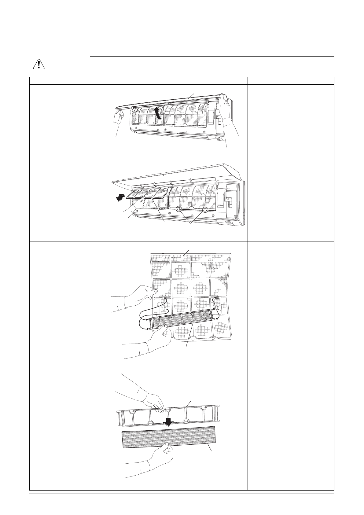
1. Remove the air filters.
Front Panel
1 Open the front panel to
the position where it
stops.
The air filter is not marked
(R16449)
2 Pull out the air filter
downward and remove
it.
for difference between the
right and left sides.
Insert the air filter with the
“FRONT” mark faced up.
The air filter can be set
easily by inserting it along
the guides.
Air filter
Hook
(R16450)
Be sure to insert the hooks
(at 2 lower positions) when
reassembling the air filter.
2. Remove the Titanium
apatite photocatalytic air-
Air filter
The right and left filters are
interchangeable.
purifying filters.
1 Remove the Titanium
apatite photocatalytic
air-purifying filter ASSY
from the back of the air
filter.
Titanium apatite photocatalytic
air-purifying filter ASSY
(R16262)
2 Remove the Titanium
apatite photocatalytic
air-purifying filter from
the frame.
2 Removal Procedure
Frame
Titanium apatite photocatalytic
air-purifying filter
(R9478)
Si041351ED Air Filters / Front Panel
Step Procedure Points
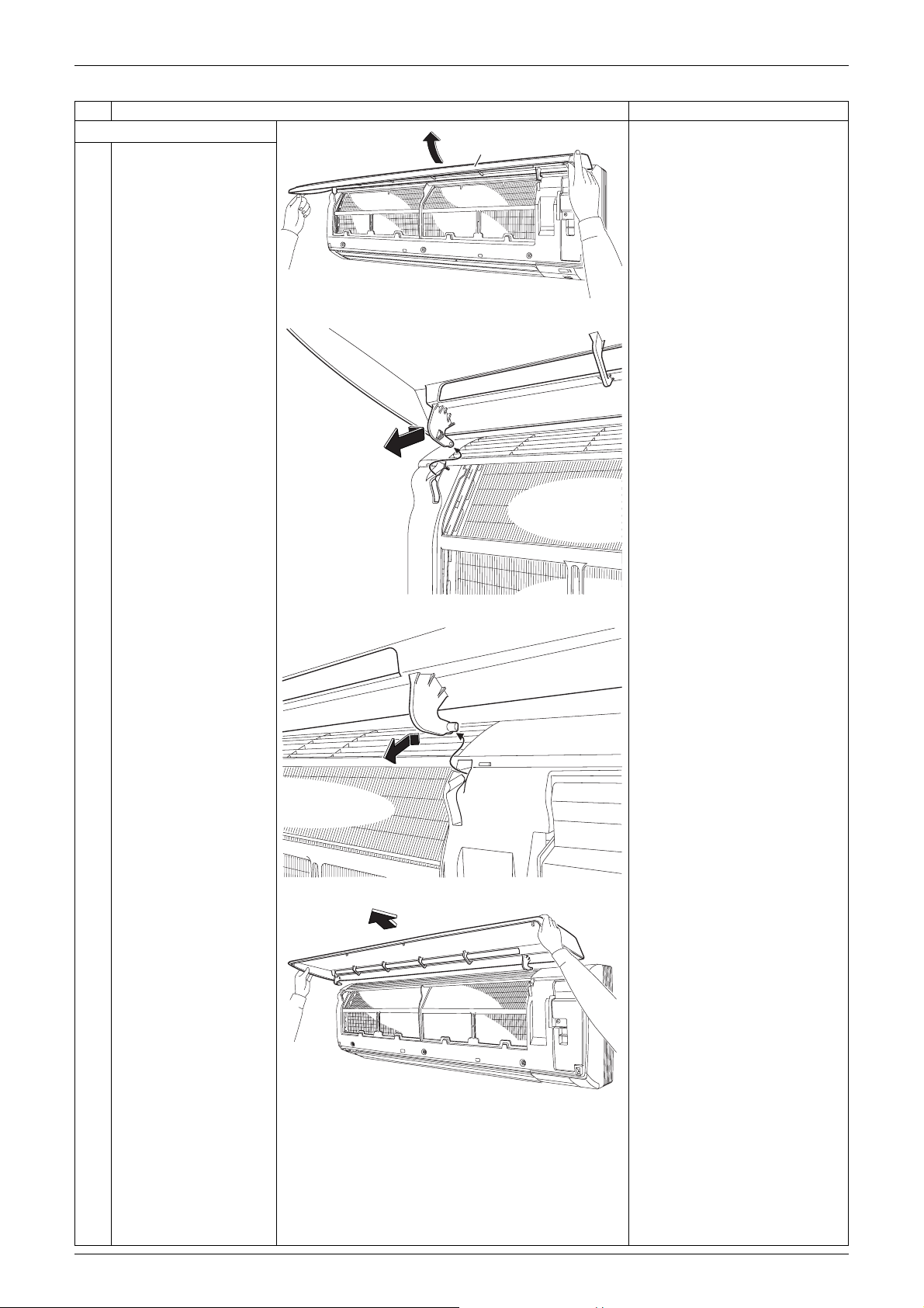
3. Remove the front panel.
1 Open the front panel
Front Panel
over the position where
it stops.
(R16456)
2 Slide the left rotary
shaft to the right and
release it.
When reassembling the front
panel, fit the right and left
rotary shafts one by one into
the grooves and fully push
them into position.
3 Release the right rotary
shaft in the same way.
4 Remove the front panel.
(R9480)
(R9481)
(R16451)
Removal Procedure 3
Front Grille Si041351ED
2. Front Grille
Warning
Be sure to wait for 10 minutes or more after turning off all power supplies before
disassembling work.
Step Procedure Points
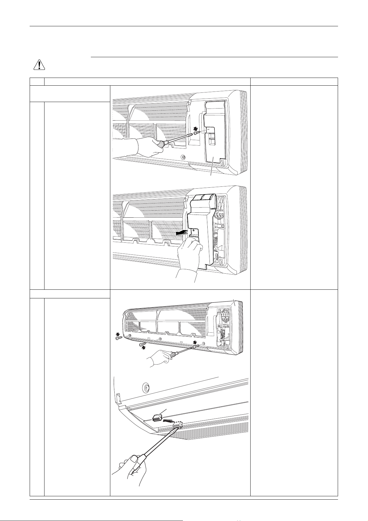
1. Remove the service
cover.
1 Remove the screw and
remove the service
cover.
Service cover
(R16452)
You can remove the front
grille without removing the
service cover.
2. Remove the front grille.
1 Remove the 3 screws
of the front grille.
2 Remove the 3 screw
covers with a flat
screwdriver.
Screw cover
(R16453)
Front grille
(R16454)
Refer to the removal
procedure in a reverse way
when reassembling.
(R20476)
4 Removal Procedure

Si041351ED Front Grille
Step Procedure Points
3 Remove the lower 3
screws.
(R16267)
4 Unfasten the 3 hooks
on the top of the front
grille.
5 Pull out the upper part
of the front grille and lift
up the lower part, and
Hook
(R16511)
The convex marks (...) on
the front panel indicate the
position of the hooks.
(R12715)
When reassembling, make
sure that all the 3 hooks are
fastened as they were.
then remove the front
grille.
(R16269)
Removal Procedure 5
Electrical Box Si041351ED
3. Electrical Box
Warning
Be sure to wait for 10 minutes or more after turning off all power supplies before
disassembling work.
Step Procedure Points
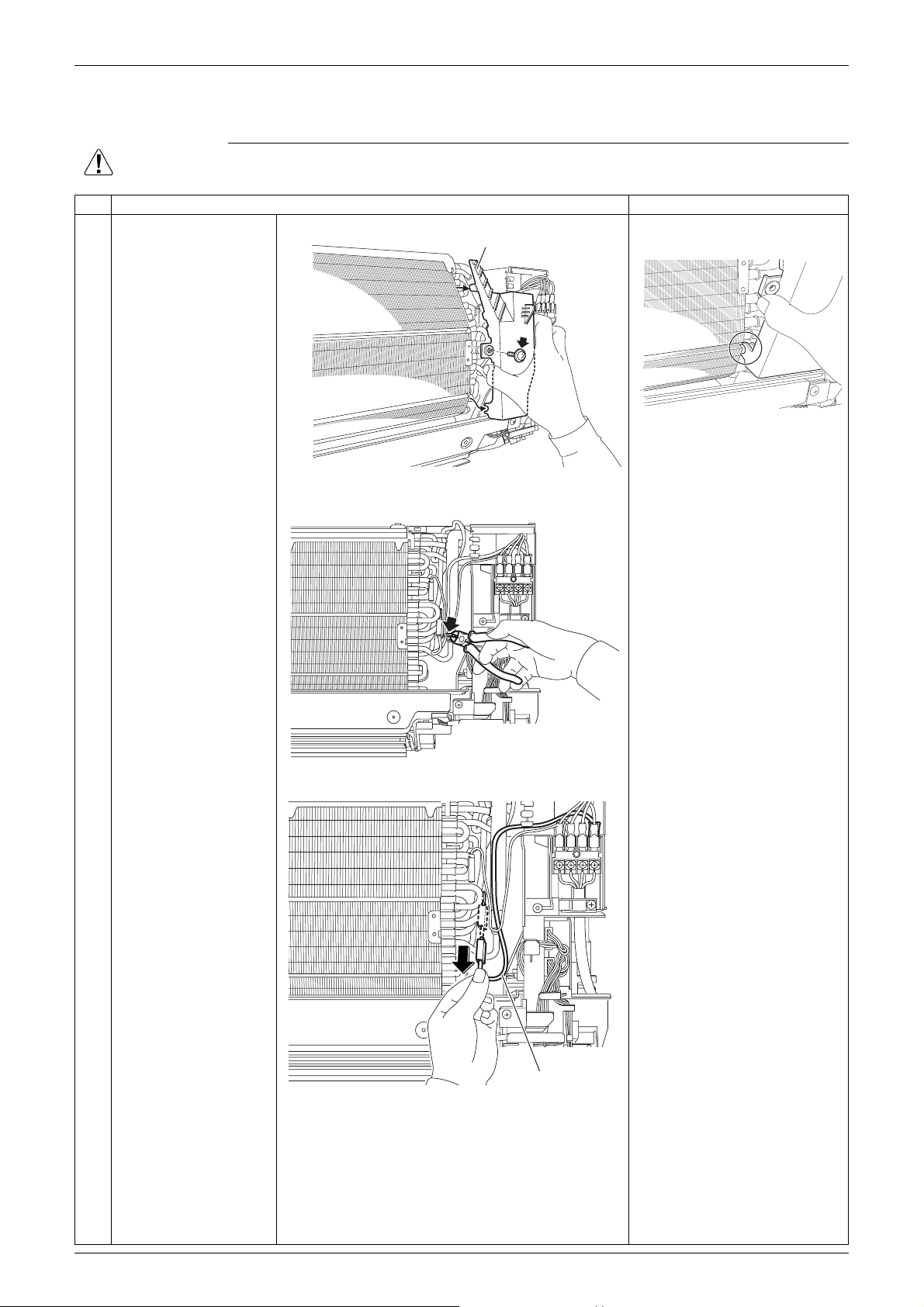
12Remove the screw.
Drip proof plate
The shape of the drip proof
plate varies by the model.
Remove the drip proof
plate from the indoor
heat exchanger.
When reassembling, fit the
hook to the indoor heat
(R18724)
exchanger.
3 Cut the clamp.
(R16273)
4 Pull out and release the
earth / ground wire.
(R16274)
Earth / ground wire
(R19306)
6 Removal Procedure
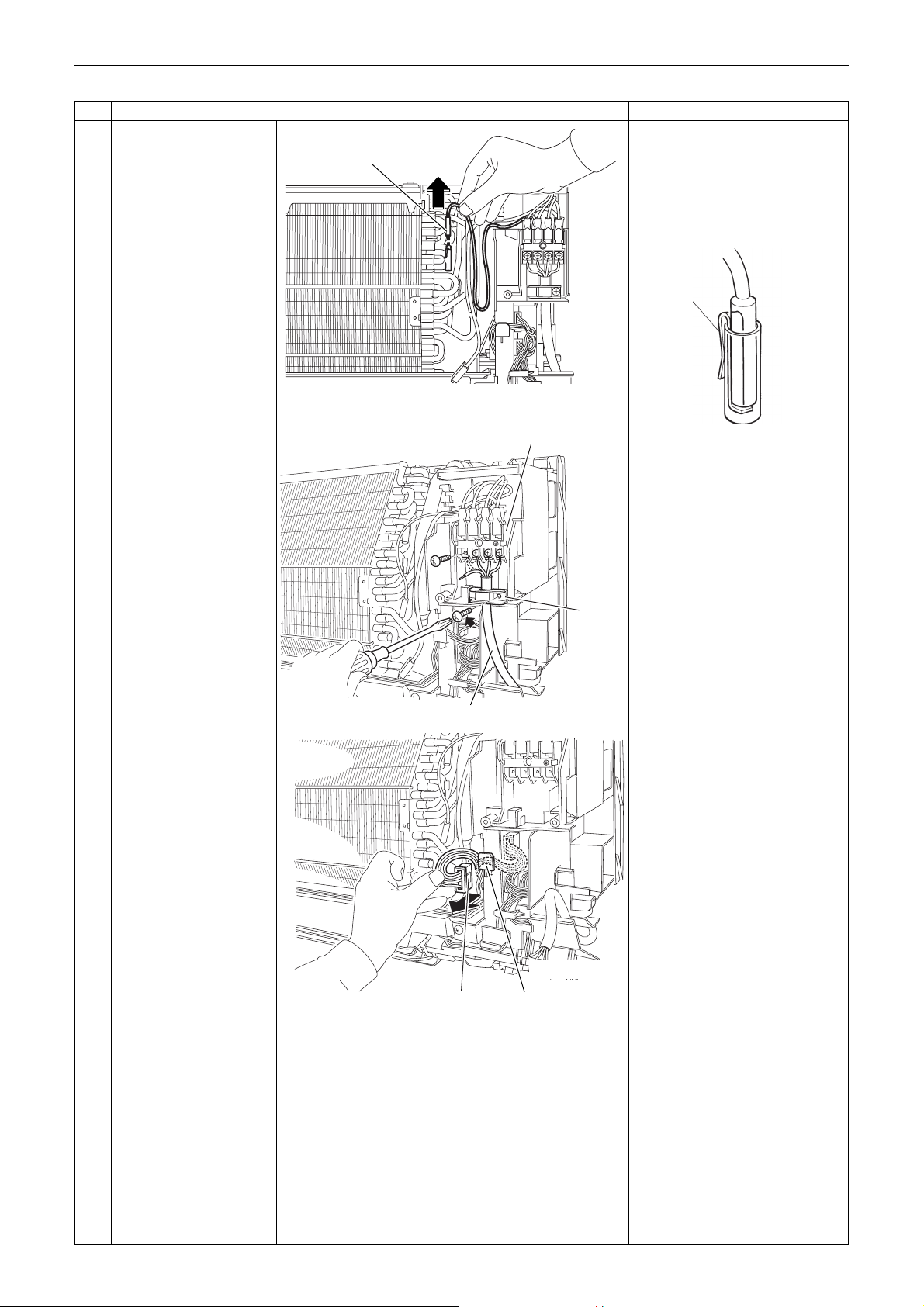
Si041351ED Electrical Box
Step Procedure Points
5 Pull out the indoor heat
exchanger thermistor.
Indoor heat exchanger
thermistor
The position of the indoor
heat exchanger thermistor
varies by the model.
Be careful not to lose the clip
of the thermistor.
Clip
(R18885)
67Remove the 4 screws
on the terminal board
and disconnect the
connecting wire.
Remove the screw and
remove the wire fixture.
8 Disconnect the
connector [S1] and
release the harness
from the hook.
Terminal board
3
2
1
Connecting wire
(R11268)
Wire
fixture
(R18886)
[S1]: fan motor
3
2
1
[S1] Hook
(R18887)
Removal Procedure 7
 Loading...