

Daikin FTXG25CVMAS, FTXG35CVMBS, FTXG35CVMBW, FTXG25CVMBS, ATXG25CVMB Service Manual
...
Inverter Pair
Wall Mounted Type C-Series
[Applied Models]
zzzzInverter Pair : Heat Pump
Si04-402A

Si04-402A
Table of Contents i
Inverter Pair
Inverter PairInverter Pair
Inverter Pair
C-Series
C-SeriesC-Series
C-Series
zHeat Pump
Indoor Unit
FTXG25CVMAW FTXG35CVMAW
FTXG25CVMAS FTXG35CVMAS
FTXG25CVMBW FTXG35CVMBW
FTXG25CVMBS FTXG35CVMBS
ATXG25CVMB ATXG35CVMB
Outdoor Unit
RXG25CVMA RXG35CVMA
RXG25CVMB RXG35CVMB
ARXG25CVMB ARXG35CVMB

Si04-402A
ii Table of Contents
1. Introduction .............................................................................................v
1.1 Safety Cautions ........................................................................................v
Part 1 List of Functions ................................................................1
1. List of Functions......................................................................................2
Part 2 Specifications .................................................................... 3
1. Specifications..........................................................................................4
Part 3 Printed Circuit Board
Connector Wiring Diagram .................................................9
1. Printed Circuit Board Connector Wiring Diagram..................................10
1.1 Indoor Unit..............................................................................................10
1.2 Outdoor Unit ...........................................................................................12
Part 4 Function and Control.......................................................15
1. Main Functions......................................................................................16
1.1 Frequency Principle................................................................................16
1.2 Power-Airflow Flap, Wide-Angle Louvres and Auto-Swing ....................18
1.3 Operation Starting Control......................................................................19
1.4 Fan Speed Control for Indoor Units........................................................20
1.5 Programme Dry Function .......................................................................21
1.6 Automatic Operation...............................................................................22
1.7 NIGHT SET Mode ..................................................................................23
1.8 INTELLIGENT EYE ................................................................................24
1.9 Inverter Powerful Operation ...................................................................25
1.10 Other Functions......................................................................................26
2. Function of Thermistor ..........................................................................27
2.1 Heat Pump Model...................................................................................27
3. Control Specification .............................................................................28
3.1 Mode Hierarchy ......................................................................................28
3.2 Frequency Control..................................................................................29
3.3 Controls at Mode Changing / Start-up....................................................30
3.4 Discharge Pipe Control ..........................................................................32
3.5 Input Current Control ..............................................................................32
3.6 Freeze-up Protection Control .................................................................33
3.7 Heating Peak-cut Control .......................................................................33
3.8 Fan Control.............................................................................................34
3.9 Liquid Compression Protection Function 2.............................................34
3.10 Defrost Control .......................................................................................35
3.11 Electronic Expansion Valve Control .......................................................36
3.12 Malfunctions ...........................................................................................39
3.13 Forced Operation Mode .........................................................................40
3.14 Additional Function.................................................................................40

Si04-402A
Table of Contents iii
Part 5 System Configuration.......................................................41
1. System Configuration............................................................................42
2. Instruction..............................................................................................43
2.1 Safety Precautions .................................................................................43
2.2 Names of Parts.......................................................................................45
2.3 Preparation before Operation .................................................................48
2.4 AUTO · DRY · COOL · HEAT · FAN Operation ......................................51
2.5 Adjusting the Air Flow Direction .............................................................53
2.6 POWERFUL Operation ..........................................................................55
2.7 OUTDOOR UNIT SILENT Operation .....................................................56
2.8 INTELLIGENT EYE Operation ...............................................................57
2.9 TIMER Operation ...................................................................................59
2.10 Care and Cleaning .................................................................................61
2.11 Troubleshooting......................................................................................64
Part 6 Service Diagnosis.............................................................67
1. Caution for Diagnosis............................................................................68
2. Problem Symptoms and Measures.......................................................69
3. Service Check Function ........................................................................70
4. Troubleshooting ....................................................................................73
4.1 Error Codes and Description ..................................................................73
4.2 Indoor Unit PCB Abnormality .................................................................74
4.3 Freeze-up Protection Control or High Pressure Control.........................75
4.4 Fan Motor (DC Motor) or Related Abnormality.......................................77
4.5 Thermistor or Related Abnormality (Indoor Unit)....................................79
4.6 Front Panel Open / Close Fault ..............................................................80
4.7 Signal Transmission Error (between Indoor and Outdoor Unit) .............81
4.8 Signal Transmission Error
(between Indoor Unit and Wired Remote Controller ) ............................82
4.9 Unspecified Voltage (between Indoor and Outdoor Unit).......................83
4.10 Outdoor Unit PCB Abnormality...............................................................84
4.11 OL Activation (Compressor Overload) ...................................................85
4.12 Compressor Lock ...................................................................................86
4.13 DC Fan Lock ..........................................................................................87
4.14 Input Over Current Detection .................................................................88
4.15 Four Way Valve Abnormality..................................................................89
4.16 Discharge Pipe Temperature Control.....................................................91
4.17 High Pressure Control in Cooling ...........................................................92
4.18 Sensor Abnormality around Compressor System ..................................94
4.19 Position Sensor Abnormality ..................................................................95
4.20 DC Voltage / Current Sensor Abnormality..............................................96
4.21 Thermistor or Related Abnormality (Outdoor Unit) .................................97
4.22 Output Over Current Detection...............................................................99
4.23 Insufficient Gas.....................................................................................101
4.24 Over-voltage Detection.........................................................................103
5. Check ..................................................................................................104
5.1 How to Check .......................................................................................104

Si04-402A
iv Table of Contents
Part 7 Removal Procedure ........................................................ 111
1. Indoor Unit...........................................................................................112
1.1 Removal of Air Filter.............................................................................112
1.2 Removal of Front Grille ........................................................................114
1.3 Removal of Assembly of Front Panel Mechanism................................120
1.4 Removal of Lamp Cover.......................................................................124
1.5 Removal of Horizontal Blade................................................................125
1.6 Removal of Reduction Motor................................................................126
1.7 Removal of Outlet Grille .......................................................................129
1.8 Removal of Vertical Blades and Swing Motor ......................................130
1.9 Removal of Electrical Box ....................................................................134
1.10 Removal of PCB...................................................................................140
1.11 Removal of Heat Exchanger ................................................................146
1.12 Removal of Fan Rotor and Fan Motor..................................................149
2. Outdoor Unit........................................................................................152
2.1 Removal of Panels and Fan Motor.......................................................152
2.2 Removal of Electrical Box ....................................................................159
2.3 Removal of Reactor and Partition Plate ...............................................161
2.4 Removal of Sound Blanket...................................................................163
2.5 Removal of Four Way Valve.................................................................165
2.6 Removal of Compressor.......................................................................167
2.7 Removal of PCB...................................................................................169
Part 8 Others ............................................................................. 173
1. Others .................................................................................................174
1.1 Test Run from the Remote Controller ..................................................174
1.2 Jumper Settings ...................................................................................175
Part 9 Appendix.........................................................................177
1. Piping Diagrams..................................................................................178
2. Wiring Diagrams..................................................................................179
Index .............................................................................................i
Drawings & Flow Charts ................................................................ v
Si04-402A Introduction
v
1. Introduction
1.1 Safety Cautions
Cautions and
Warnings
Be sure to read the following safety cautions before conducting repair work.
The caution items are classified into “ Warning” and “ Caution”. The “ Warning”
items are especially important since they can lead to death or serious injury if they are not
followed closely. The “ Caution” items can also lead to serious accidents under some
conditions if they are not followed. Therefore, be sure to observe all the safety caution items
described below.
About the pictograms
This symbol indicates an item for which caution must be exercised.
The pictogram shows the item to which attention must be paid.
This symbol indicates a prohibited action.
The prohibited item or action is shown inside or near the symbol.
This symbol indicates an action that must be taken, or an instruction.
The instruction is shown inside or near the symbol.
After the repair work is complete, be sure to conduct a test operation to ensure that the
equipment operates normally, and explain the cautions for operating the product to the
customer.
1.1.1 Caution in Repair
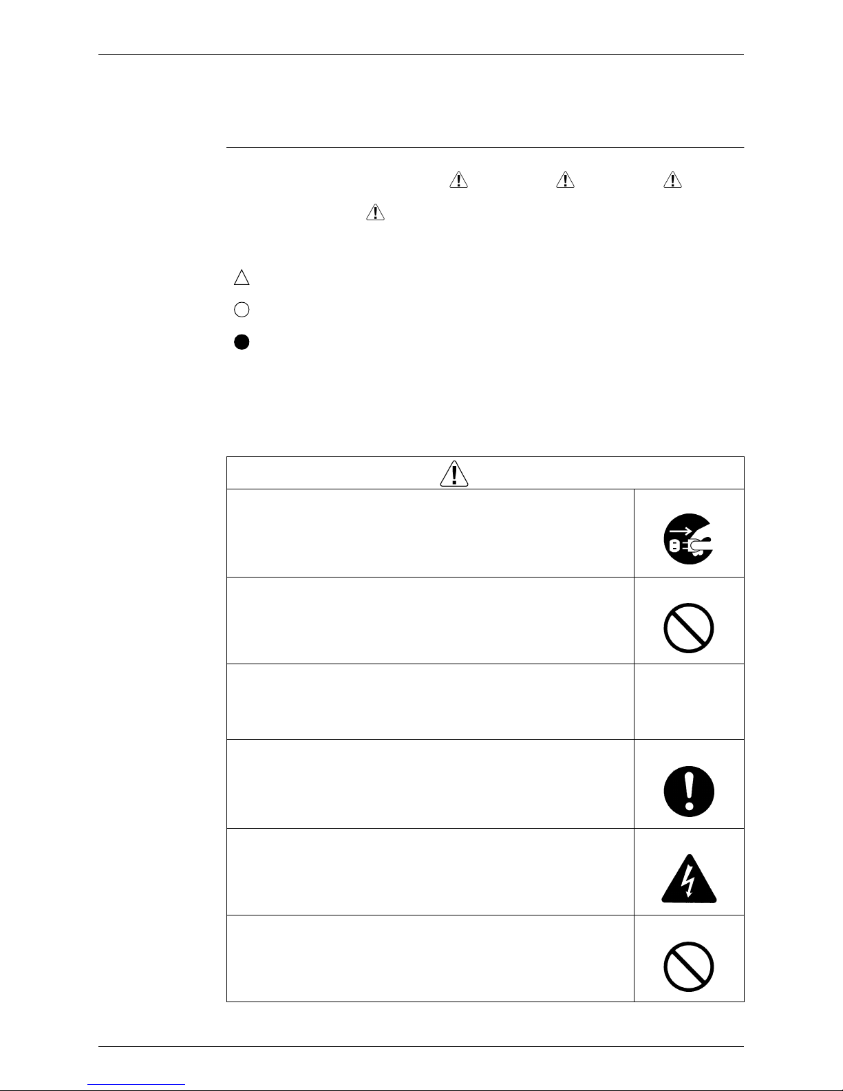
Warning
Be sure to disconnect the power cable plug from the plug socket before
disassembling the equipment for a repair.
Working on the equipment that is connected to a power supply can cause an
electrical shook.
If it is necessary to supply power to the equipment to conduct the repair or
inspecting the circuits, do not touch any electrically charged sections of the
equipment.
If the refrigerant gas discharges during the repair work, do not touch the
discharging refrigerant gas.
The refrigerant gas can cause frostbite.
When disconnecting the suction or discharge pipe of the compressor at the
welded section, release the refrigerant gas completely at a well-ventilated
place first.
If there is a gas remaining inside the compressor, the refrigerant gas or
refrigerating machine oil discharges when the pipe is disconnected, and it can
cause injury.
If the refrigerant gas leaks during the repair work, ventilate the area. The
refrigerant gas can generate toxic gases when it contacts flames.
The step-up capacitor supplies high-voltage electricity to the electrical
components of the outdoor unit.
Be sure to discharge the capacitor completely before conducting repair work.
A charged capacitor can cause an electrical shock.
Do not start or stop the air conditioner operation by plugging or unplugging the
power cable plug.
Plugging or unplugging the power cable plug to operate the equipment can
cause an electrical shock or fire.
Introduction Si04-402A
vi
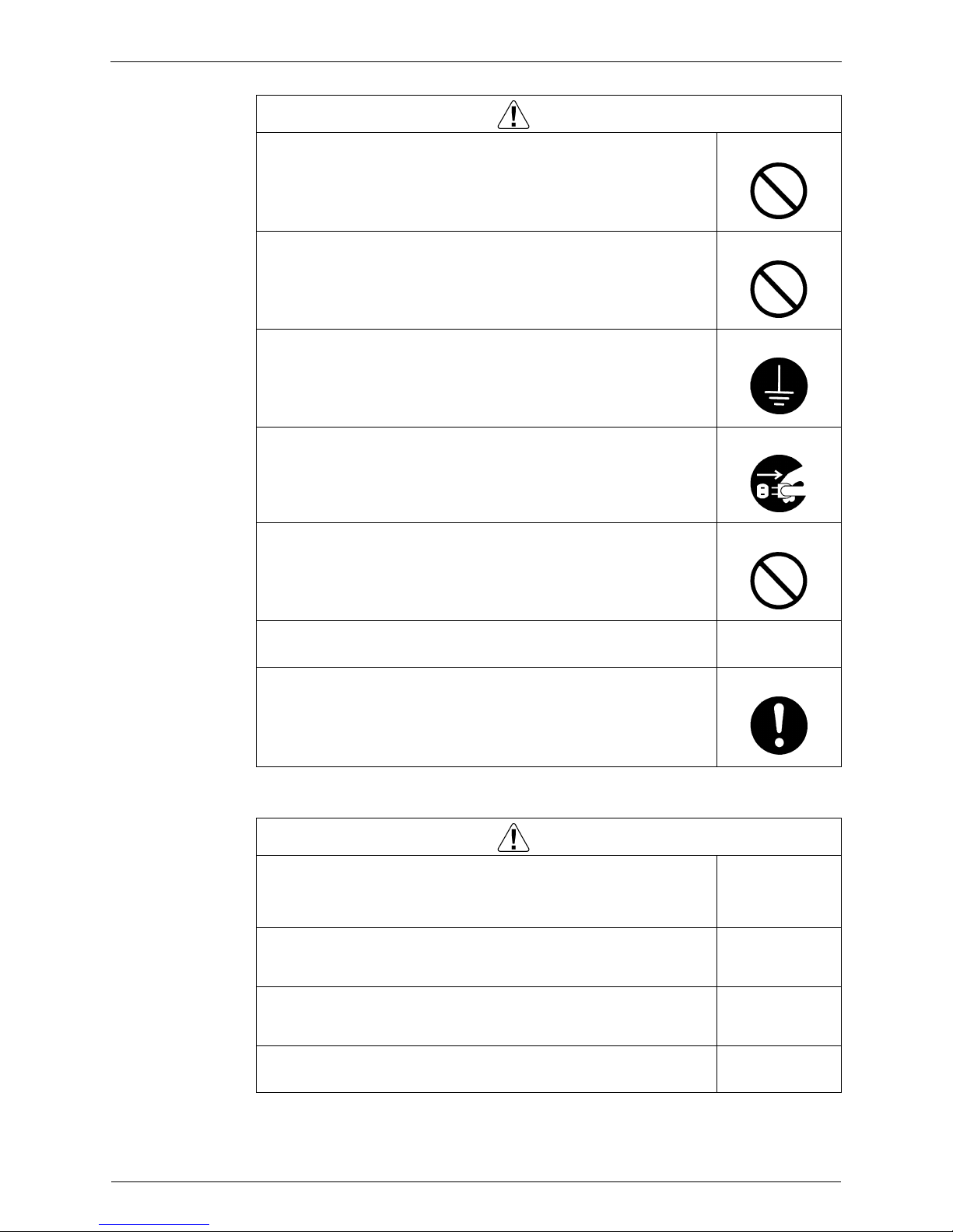
1.1.2 Cautions Regarding Products after Repair
Do not repair the electrical components with wet hands.
Working on the equipment with wet hands can cause an electrical shock.
Do not clean the air conditioner by splashing water.
Washing the unit with water can cause an electrical shock.
Be sure to provide the grounding when repairing the equipment in a humid or
wet place, to avoid electrical shocks.
Be sure to turn off the power switch and unplug the power cable when cleaning
the equipment.
The internal fan rotates at a high speed, and cause injury.
Do not tilt the unit when removing it.
The water inside the unit can spill and wet the furniture and floor.
Be sure to check that the refrigerating cycle section has cooled down
sufficiently before conducting repair work.
Working on the unit when the refrigerating cycle section is hot can cause burns.
Use the welder in a well-ventilated place.
Using the welder in an enclosed room can cause oxygen deficiency.
Warning
Warning
Be sure to use parts listed in the service parts list of the applicable model and
appropriate tools to conduct repair work. Never attempt to modify the
equipment.
The use of inappropriate parts or tools can cause an electrical shock,
excessive heat generation or fire.
When relocating the equipment, make sure that the new installation site has
sufficient strength to withstand the weight of the equipment.
If the installation site does not have sufficient strength and if the installation
work is not conducted securely, the equipment can fall and cause injury.
Be sure to install the product correctly by using the provided standard
installation frame.
Incorrect use of the installation frame and improper installation can cause the
equipment to fall, resulting in injury.
For integral units
only
Be sure to install the product securely in the installation frame mounted on a
window frame.
If the unit is not securely mounted, it can fall and cause injury.
For integral units
only
Si04-402A Introduction
vii
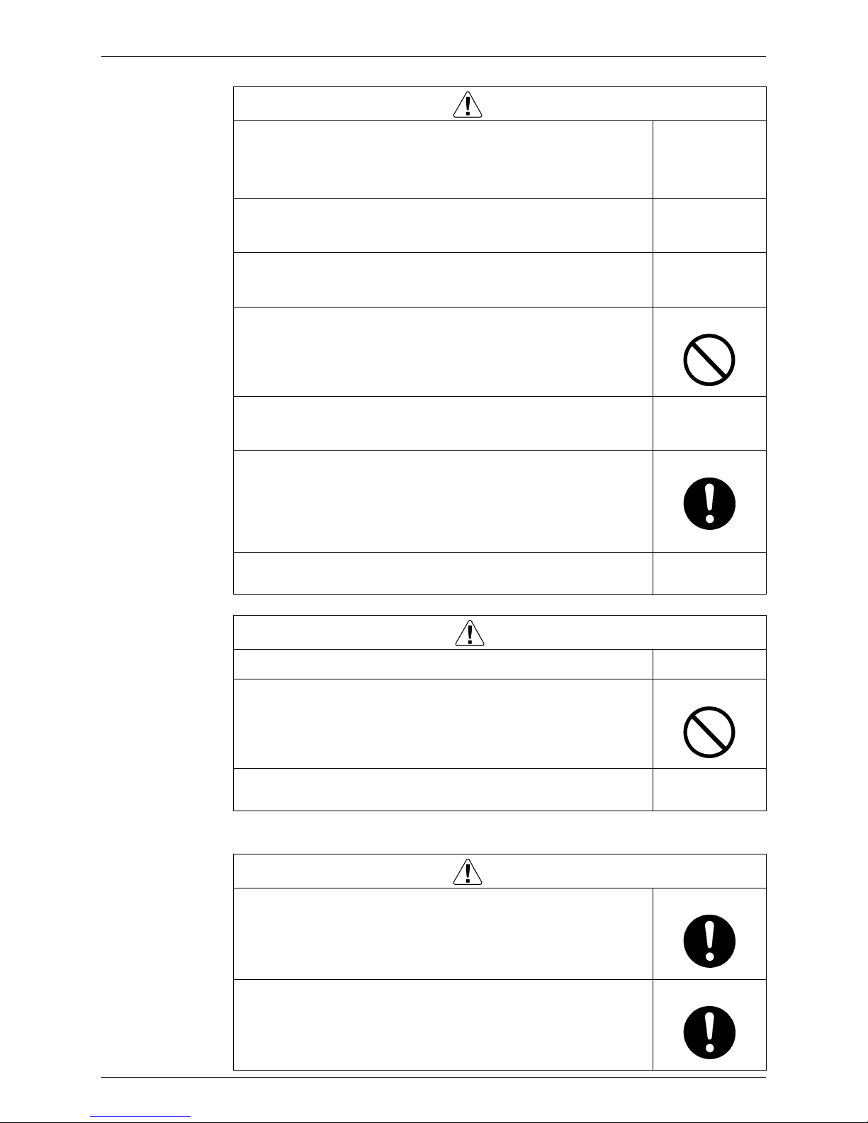
1.1.3 Inspection after Repair
Be sure to use an exclusive power circuit for the equipment, and follow the
technical standards related to the electrical equipment, the internal wiring
regulations and the instruction manual for installation when conducting
electrical work.
Insufficient power circuit capacity and improper electrical work can cause an
electrical shock or fire.
Be sure to use the specified cable to connect between the indoor and outdoor
units. Make the connections securely and route the cable properly so that there
is no force pulling the cable at the connection terminals.
Improper connections can cause excessive heat generation or fire.
When connecting the cable between the indoor and outdoor units, make sure
that the terminal cover does not lift off or dismount because of the cable.
If the cover is not mounted properly, the terminal connection section can cause
an electrical shock, excessive heat generation or fire.
Do not damage or modify the power cable.
Damaged or modified power cable can cause an electrical shock or fire.
Placing heavy items on the power cable, and heating or pulling the power cable
can damage the cable.
Do not mix air or gas other than the specified refrigerant (R410A / R22) in the
refrigerant system.
If air enters the refrigerating system, an excessively high pressure results,
causing equipment damage and injury.
If the refrigerant gas leaks, be sure to locate the leak and repair it before
charging the refrigerant. After charging refrigerant, make sure that there is no
refrigerant leak.
If the leak cannot be located and the repair work must be stopped, be sure to
perform pump-down and close the service valve, to prevent the refrigerant gas
from leaking into the room. The refrigerant gas itself is harmless, but it can
generate toxic gases when it contacts flames, such as fan and other heaters,
stoves and ranges.
When replacing the coin battery in the remote controller, be sure to disposed
of the old battery to prevent children from swallowing it.
If a child swallows the coin battery, see a doctor immediately.
Warning
Caution
Installation of a leakage breaker is necessary in some cases depending on the
conditions of the installation site, to prevent electrical shocks.
Do not install the equipment in a place where there is a possibility of
combustible gas leaks.
If a combustible gas leaks and remains around the unit, it can cause a fire.
Be sure to install the packing and seal on the installation frame properly.
If the packing and seal are not installed properly, water can enter the room and
wet the furniture and floor.
For integral units
only
Warning
Check to make sure that the power cable plug is not dirty or loose, then insert
the plug into a power outlet all the way.
If the plug has dust or loose connection, it can cause an electrical shock or fire.
If the power cable and lead wires have scratches or deteriorated, be sure to
replace them.
Damaged cable and wires can cause an electrical shock, excessive heat
generation or fire.
Introduction Si04-402A
viii
1.1.4 Using Icons
Icons are used to attract the attention of the reader to specific information. The meaning of each
icon is described in the table below:
1.1.5 Using Icons List
Do not use a joined power cable or extension cable, or share the same power
outlet with other electrical appliances, since it can cause an electrical shock,
excessive heat generation or fire.
Warning
Caution
Check to see if the parts and wires are mounted and connected properly, and
if the connections at the soldered or crimped terminals are secure.
Improper installation and connections can cause excessive heat generation,
fire or an electrical shock.
If the installation platform or frame has corroded, replace it.
Corroded installation platform or frame can cause the unit to fall, resulting in
injury.
Check the grounding, and repair it if the equipment is not properly grounded.
Improper grounding can cause an electrical shock.
Be sure to measure the insulation resistance after the repair, and make sure
that the resistance is 1 Mohm or higher.
Faulty insulation can cause an electrical shock.
Be sure to check the drainage of the indoor unit after the repair.
Faulty drainage can cause the water to enter the room and wet the furniture
and floor.
Icon Type of
Information
Description
Note:
Note A “note” provides information that is not indispensable, but may
nevertheless be valuable to the reader, such as tips and tricks.
Caution
Caution A “caution” is used when there is danger that the reader, through
incorrect manipulation, may damage equipment, loose data, get
an unexpected result or has to restart (part of) a procedure.
Warning
Warning A “warning” is used when there is danger of personal injury.
Reference A “reference” guides the reader to other places in this binder or
in this manual, where he/she will find additional information on a
specific topic.

Si04-402A
List of Functions 1
Part 1
Part 1Part 1
Part 1
List of Functions
List of FunctionsList of Functions
List of Functions
1. List of Functions......................................................................................2
List of Functions Si04-402A
2 List of Functions
1. List of Functions
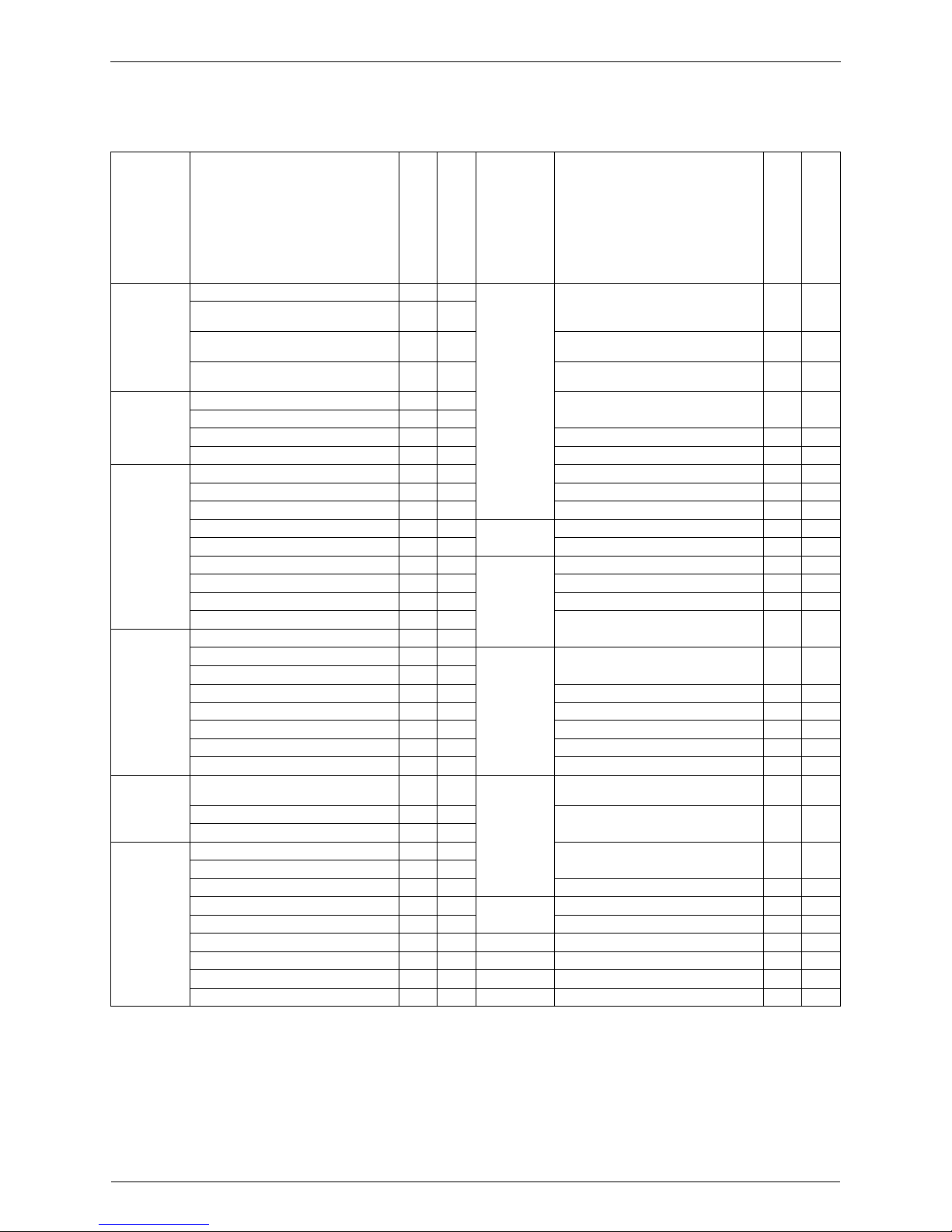
Category Functions
FTXG25/35CVMAW(S)
FTXG25/35CVMBW(S)
RXG25/35CVMA(B)
ATXG25/35CVMBW(S)
ARXG25/35CVMB
Category Functions
FTXG25/35CVMAW(S)
FTXG25/35CVMBW(S)
RXG25/35CVMA(B)
ATXG25/35CVMBW(S)
ARXG25/35CVMB
Basic
Function
Inverter (with Inverter Power Control)
{{
Health &
Clean
Air Purifying Filter with Bacteriostatic,
Virustatic Functions
——
Operation Limit for Cooling (°CDB)
10
~4610~46
Operation Limit for Heating (°CWB)
–15
~20
–15
~20
Photocatalytic Deodorizing Filter — —
PAM Control
{{
Air Purifying Filter with Photocatalytic
Deodorizing Function
——
Compressor
Oval Scroll Compressor — —
Titanium Apatite Photocatalytic
Air-Purifying Filter
{{
Swing Compressor
{{
Rotary Compressor — — Mold Proof Air Filter
{{
Reluctance DC Motor
{{
Wipe-clean Flat Panel
{{
Comfortable
Airflow
Power-Airflow Flap
{{
Washable Grille — —
Power-Airflow Dual Flaps — — Filter Cleaning Indicator — —
Power-Airflow Diffuser — — Good-Sleep Cooling Operation — —
Wide-Angle Louvers
{{
Timer
24-Hour On/Off Timer
{{
Vertical Auto-Swing (Up and Down)
{{
Night Set Mode
{{
Horizontal Auto-Swing (Right and Left)
{{
Worry Free
“Reliability &
Durability”
Auto-Restart (after Power Failure)
{{
3-D Airflow
{{
Self-Diagnosis (Digital, LED) Display
{{
Comfort Airflow Mode
{{
Wiring Error Check — —
3-Step Airflow (H/P Only) — —
Anticorrosion Treatment of Outdoor
Heat Exchanger
{{
Comfort
Control
Auto Fan Speed
{{
Indoor Unit Silent Operation
{{
Flexibility
Multi-Split / Split Type Compatible
Indoor Unit
——
Night Quiet Mode (Automatic) — —
Outdoor Unit Silent Operation (Manual)
{{
Flexible Voltage Correspondence
{{
Intelligent Eye
{{
High Ceiling Application — —
Quick Warming Function
{{
Chargeless 10m 10m
Hot-Start Function
{{
Either Side Drain (Right or Left)
{{
Automatic Defrosting
{{
Power Selection — —
Operation
Automatic Operation
{{
Remote
Control
5-Rooms Centralized Controller
(Option)
{{
Programme Dry Function
{{
Remote Control Adaptor
(Normal Open-Pulse Contact)(Option)
{{
Fan Only
{{
Lifestyle
Convenience
New Powerful Operation (Non-Inverter) — —
Remote Control Adaptor
(Normal Open Contact)(Option)
{{
Inverter Powerful Operation
{{
Priority-Room Setting — — DIII-NET Compatible (Adaptor)(Option)
{{
Cooling / Heating Mode Lock — —
Remote
Controller
Wireless
{{
Home Leave Operation — — Wired — —
Indoor Unit On/Off Switch
{{
Signal Reception Indicator
{{
Temperature Display — —
Another Room Operation — —
Note:
{
: Holding Functions
— : No Functions

Si04-402A
Specifications 3
Part 2
Part 2Part 2
Part 2
Specifications
SpecificationsSpecifications
Specifications
1. Specifications..........................................................................................4
Specifications Si04-402A
4 Specifications
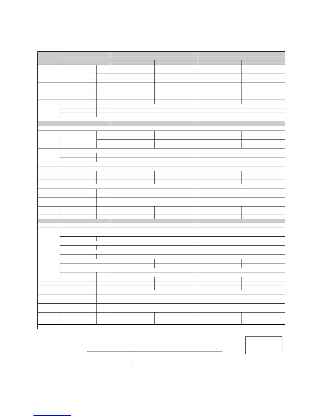
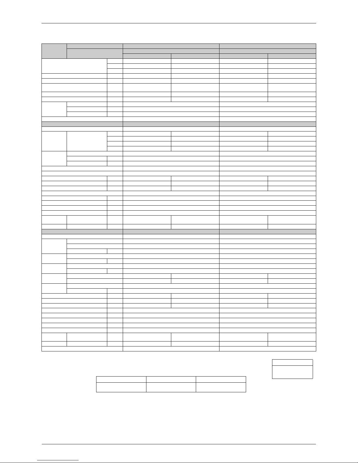
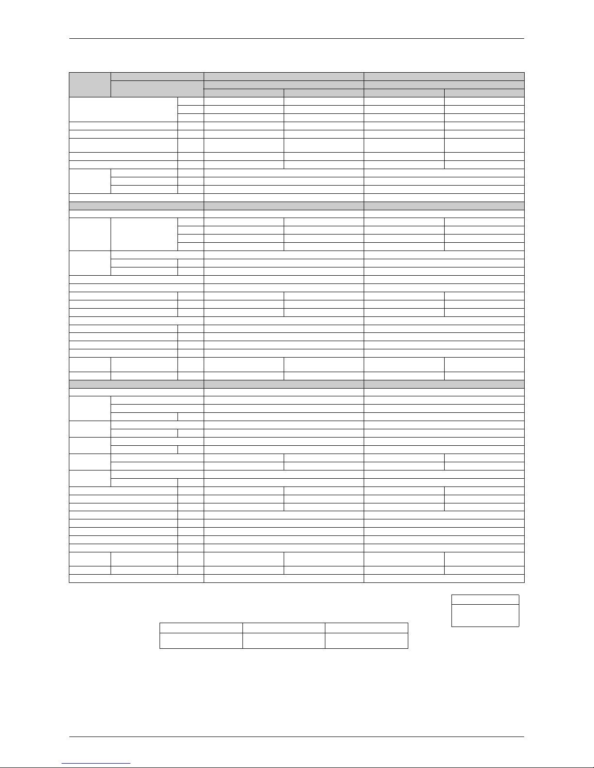
1. Specifications
230V, 50Hz
Notes:
MAX. interunit piping length: 20m
MAX. interunit height difference: 15m
Amount of additional charge of refrigerant 20g/m for piping length exceeding 10m
The data are based on the conditions shown in the table below.
Model
Indoor Units FTXG25CVMAW FTXG25CVMAS
Outdoor Units
RXG25CVMA RXG25CVMA
Cooling Heating Cooling Heating
Capacity
Rated (Min.~Max.)
kW 2.5 (1.3~3.0) 3.4 (1.3~4.5) 2.5 (1.3~3.0) 3.4 (1.3~4.5)
Btu/h 8,550 (4,450~10,250) 11,600 (4,450~15,350) 8,550 (4,450~10,250) 11,600 (4,450~15,350)
kcal/h 2,150 (1,120~2,580) 2,920 (1,120~3,870) 2,150 (1,120~2,580) 2,920 (1,120~3,870)
Moisture Removal L/h 1.2 — 1.2 —
Running Current (Rated) A 3.4 4.5 3.4 4.5
Power Consumption
Rated (Min.~Max.)
W 620 (300~950) 825 (290~1,420) 620 (300~950) 825 (290~1,420)
Power Factor % 79.3 79.7 79.3 79.7
COP W/W 4.03 4.12 4.03 4.12
Piping
Connections
Liquid mm φ 6.4 φ 6.4
Gas mm φ 9.5 φ 9.5
Drain mm φ18.0 φ18.0
Heat Insulation Both Liquid and Gas Pipes Both Liquid and Gas Pipes
Indoor Unit FTXG25CVMAW FTXG25CVMAS
Front Panel Color Mat Crystal White Mat Crystal Silver
Air Flow Rate
m³/min
(cfm)
H 7.9 (278) 8.2 (289) 7.9 (278) 8.2 (289)
M 6.7 (236) 7.3 (257) 6.7 (236) 7.3 (257)
L 5.4 (190) 6.3 (222) 5.4 (190) 6.3 (222)
SL 4.7 (165) 5.4 (190) 4.7 (165) 5.4 (190)
Fan
Type Cross Flow Fan Cross Flow Fan
Motor Output W 40 40
Speed Steps 5 Steps, Silent and Auto 5 Steps, Silent and Auto
Air Direction Control Right, Left, Horizontal and Downward Right, Left, Horizontal and Downward
Air Filter Removable / Washable / Mildew Proof Removable / Washable / Mildew Proof
Running Current (Rated) A 0.14 0.14 0.14 0.14
Power Consumption (Rated) W 30 30 30 30
Power Factor % 93.2 93.2 93.2 93.2
Temperature Control Microcomputer Control Microcomputer Control
Dimensions (H×W×D) mm 275×840×150 275×840×150
Packaged Dimensions (H×W×D) mm 222×894×345 222×894×345
Weigh t kg 9 9
Gross Weight kg 13 13
Operation
Sound
H/M/L/SL dBA 38/34/30/27 38/34/30/27 38/34/30/27 38/34/30/27
Sound Power H dBA 56 56 56 56
Outdoor Unit RXG25CVMA RXG25CVMA
Casing Color Ivory White Ivory White
Compressor
Type Hermetically Sealed Swing Type Hermetically Sealed Swing Type
Model 1YC23NXD#A 1YC23NXD#A
Motor Output W 600 600
Refrigerant
Oil
Model FVC50K FVC50K
Charge L 0.375 0.375
Refrigerant
Model R410A R410A
Charge kg 1.00 1.00
Air Flow Rat e
(H/L)
m³/min 31.3/22.4 28.1/22.4 31.3/22.4 28.1/22.4
cfm 1,105/791 992/791 1,105/791 992/791
Fan
Type Propeller Propeller
Motor Output W 35 35
Running Current (Rated) A 3.26 4.36 3.26 4.36
Power Consumption (Rated) W 590 795 590 795
Power Factor % 78.7 79.3 78.7 79.3
Starting Current A 4.5 4.5
Dimensions (H×W×D) mm 550×765×285 550×765×285
Packaged Dimensions (H×W×D) mm 589×882×363 589×882×363
Weight kg 32 32
Gross Weight kg 38 38
Operation
Sound
H/L dBA 46/43 47/44 46/43 47/44
Sound Power H dBA 61 62 61 62
Drawing No. 3D046343A 3D046344A
Conversion Formulae
kcal/h=kW×860
Btu/h=kW×3414
cfm=m³/min×35.3
Cooling Heating Piping Length
Indoor ; 27°CDB/19°CWB
Outdoor ; 35°CDB/24°CWB
Indoor ; 20°CDB
Outdoor ; 7°CDB/6°CWB
7.5m

Si04-402A Specifications
Specifications 5
230V, 50Hz
Notes:
MAX. interunit piping length: 20m
MAX. interunit height difference: 15m
Amount of additional charge of refrigerant 20g/m for piping length exceeding 10m
The data are based on the conditions shown in the table below.
Model
Indoor Units FTXG25CVMBW FTXG25CVMBS
Outdoor Units
RXG25CVMB RXG25CVMB
Cooling Heating Cooling Heating
Capacity
Rated (Min.~Max.)
kW 2.5 (1.3~3.0) 3.4 (1.3~4.5) 2.5 (1.3~3.0) 3.4 (1.3~4.5)
Btu/h 8,550 (4,450~10,250) 11,600 (4,450~15,350) 8,550 (4,450~10,250) 11,600 (4,450~15,350)
kcal/h 2,150 (1,120~2,580) 2,920 (1,120~3,870) 2,150 (1,120~2,580) 2,920 (1,120~3,870)
Moisture Removal L/h 1.2 — 1.2 —
Running Current (Rated) A 3.4 4.5 3.4 4.5
Power Consumption
Rated (Min.~Max.)
W 620 (300~950) 825 (290~1,420) 620 (300~950) 825 (290~1,420)
Power Factor % 79.3 79.7 79.3 79.7
COP W/W 4.03 4.12 4.03 4.12
Piping
Connections
Liquid mm φ 6.4 φ 6.4
Gas mm φ 9.5 φ 9.5
Drain mm φ18.0 φ18.0
Heat Insulation Both Liquid and Gas Pipes Both Liquid and Gas Pipes
Indoor Unit FTXG25CVMBW FTXG25CVMBS
Front Panel Color Mat Crystal White Mat Crystal Silver
Air Flow Rate
m³/min
(cfm)
H 7.4 (260) 7.7 (271) 7.4 (260) 7.7 (271)
M 6.0 (211) 6.9 (243) 6.0 (211) 6.9 (243)
L 4.4 (155) 6.0 (211) 4.4 (155) 6.0 (211)
SL 3.7 (130) 5.0 (176) 3.7 (130) 5.0 (176)
Fan
Type Cross Flow Fan Cross Flow Fan
Motor Output W 40 40
Speed Steps 5 Steps, Silent and Auto 5 Steps, Silent and Auto
Air Direction Control Right, Left, Horizontal and Downward Right, Left, Horizontal and Downward
Air Filter Removable / Washable / Mildew Proof Removable / Washable / Mildew Proof
Running Current (Rated) A 0.14 0.14 0.14 0.14
Power Consumption (Rated) W 30 30 30 30
Power Factor % 93.2 93.2 93.2 93.2
Temperature Control Microcomputer Control Microcomputer Control
Dimensions (H×W×D) mm 275×840×150 275×840×150
Packaged Dimensions (H×W×D) mm 222×894×345 222×894×345
Weigh t kg 9 9
Gross Weight kg 13 13
Operation
Sound
H/M/L/SL dBA 38/32/25/22 38/33/28/25 38/32/25/22 38/33/28/25
Sound Power H dBA 56 — 56 —
Outdoor Unit RXG25CVMB RXG25CVMB
Casing Color Ivory White Ivory White
Compressor
Type Hermetically Sealed Swing Type Hermetically Sealed Swing Type
Model 1YC23NXD#A 1YC23NXD#A
Motor Output W 600 600
Refrigerant
Oil
Model FVC50K FVC50K
Charge L 0.375 0.375
Refrigerant
Model R410A R410A
Charge kg 1.00 1.00
Air Flow Rat e
(H/L)
m³/min 31.3/22.4 28.1/22.4 31.3/22.4 28.1/22.4
cfm 1,105/791 992/791 1,105/791 992/791
Fan
Type Propeller Propeller
Motor Output W 35 35
Running Current (Rated) A 3.26 4.36 3.26 4.36
Power Consumption (Rated) W 590 795 590 795
Power Factor % 78.7 79.3 78.7 79.3
Starting Current A 4.5 4.5
Dimensions (H×W×D) mm 550×765×285 550×765×285
Packaged Dimensions (H×W×D) mm 589×882×363 589×882×363
Weight kg 32 32
Gross Weight kg 38 38
Operation
Sound
H/L dBA 46/43 47/44 46/43 47/44
Sound Power H dBA 61 — 61 —
Drawing No. 3D045212 3D045213
Conversion Formulae
kcal/h=kW×860
Btu/h=kW×3414
cfm=m³/min×35.3
Cooling Heating Piping Length
Indoor ; 27°CDB/19°CWB
Outdoor ; 35°CDB/24°CWB
Indoor ; 20°CDB
Outdoor ; 7°CDB/6°CWB
7.5m
Specifications Si04-402A
6 Specifications
230V, 50Hz
Notes:
MAX. interunit piping length: 20m
MAX. interunit height difference: 15m
Amount of additional charge of refrigerant 20g/m for piping length exceeding 10m
The data are based on the conditions shown in the table below.
Model
Indoor Units FTXG35CVMAW FTXG35CVMAS
Outdoor Units
RXG35CVMA RXG35CVMA
Cooling Heating Cooling Heating
Capacity
Rated (Min.~Max.)
kW 3.5 (1.4~3.8) 4.2 (1.4~5.0) 3.5 (1.4~3.8) 4.2 (1.4~5.0)
Btu/h 11,950 (4,750~12,950) 14,300 (4,750~17,050) 11,950 (4,750~12,950) 14,300 (4,750~17,050)
kcal/h 3,010 (1,200~3,270) 3,610 (1,200~4,300) 3,010 (1,200~3,270) 3,610 (1,200~4,300)
Moisture Removal L/h 1.9 — 1.9 —
Running Current (Rated) A 4.9 5.2 4.9 5.2
Power Consumption
Rated (Min.~Max.)
W 1,060 (300~1,290) 1,135 (310~1,560) 1,060 (300~1,290) 1,135 (310~1,560)
Power Factor % 94.0 94.9 94.0 94.9
COP W/W 3.30 3.70 3.30 3.70
Piping
Connections
Liquid mm φ 6.4 φ 6.4
Gas mm φ 9.5 φ 9.5
Drain mm φ18.0 φ18.0
Heat Insulation Both Liquid and Gas Pipes Both Liquid and Gas Pipes
Indoor Unit FTXG35CVMAW FTXG35CVMAS
Front Panel Color Mat Crystal White Mat Crystal Silver
Air Flow Rate
m³/min
(cfm)
H 8.2 (289) 8.4 (296) 8.2 (289) 8.4 (296)
M 7.1 (250) 7.5 (264) 7.1 (250) 7.5 (264)
L 5.8 (204) 6.3 (222) 5.8 (204) 6.3 (222)
SL 4.9 (172) 5.5 (194) 4.9 (172) 5.5 (194)
Fan
Type Cross Flow Fan Cross Flow Fan
Motor Output W 40 40
Speed Steps 5 Steps, Silent and Auto 5 Steps, Silent and Auto
Air Direction Control Right, Left, Horizontal and Downward Right, Left, Horizontal and Downward
Air Filter Removable / Washable / Mildew Proof Removable / Washable / Mildew Proof
Running Current (Rated) A 0.14 0.14 0.14 0.14
Power Consumption (Rated) W 30 30 30 30
Power Factor % 93.2 93.2 93.2 93.2
Temperature Control Microcomputer Control Microcomputer Control
Dimensions (H×W×D) mm 275×840×150 275×840×150
Packaged Dimensions (H×W×D) mm 222×894×345 222×894×345
Weigh t kg 9 9
Gross Weight kg 13 13
Operation
Sound
H/M/L/SL dBA 39/35/32/29 39/35/31/28 39/35/32/29 39/35/31/28
Sound Power H dBA 57 57 57 57
Outdoor Unit RXG35CVMA RXG35CVMA
Casing Color Ivory White Ivory White
Compressor
Type Hermetically Sealed Swing Type Hermetically Sealed Swing Type
Model 1YC23NXD#A 1YC23NXD#A
Motor Output W 600 600
Refrigerant
Oil
Model FVC50K FVC50K
Charge L 0.375 0.375
Refrigerant
Model R410A R410A
Charge kg 1.00 1.00
Air Flow Rat e
(H/L)
m³/min 31.3/22.4 28.1/22.4 31.3/22.4 28.1/22.4
cfm 1,105/791 992/791 1,105/791 992/791
Fan
Type Propeller Propeller
Motor Output W 35 35
Running Current (Rated) A 4.76 5.06 4.76 5.06
Power Consumption (Rated) W 1,030 1,105 1,030 1,105
Power Factor % 94.1 94.9 94.1 94.9
Starting Current A 5.2 5.2
Dimensions (H×W×D) mm 550×765×285 550×765×285
Packaged Dimensions (H×W×D) mm 589×882×363 589×882×363
Weight kg 32 32
Gross Weight kg 38 38
Operation
Sound
H/L dBA 47/44 48/45 47/44 48/45
Sound Power H dBA 62 63 62 63
Drawing No. 3D046345A 3D046346A
Conversion Formulae
kcal/h=kW×860
Btu/h=kW×3414
cfm=m³/min×35.3
Cooling Heating Piping Length
Indoor ; 27°CDB/19°CWB
Outdoor ; 35°CDB/24°CWB
Indoor ; 20°CDB
Outdoor ; 7°CDB/6°CWB
7.5m
Si04-402A Specifications
Specifications 7
230V, 50Hz
Notes:
MAX. interunit piping length: 20m
MAX. interunit height difference: 15m
Amount of additional charge of refrigerant 20g/m for piping length exceeding 10m
The data are based on the conditions shown in the table below.
Model
Indoor Units FTXG35CVMBW FTXG35CVMBS
Outdoor Units
RXG35CVMB RXG35CVMB
Cooling Heating Cooling Heating
Capacity
Rated (Min.~Max.)
kW 3.5 (1.4~3.8) 4.2 (1.4~5.0) 3.5 (1.4~3.8) 4.2 (1.4~5.0)
Btu/h 11,950 (4,750~12,950) 14,300 (4,750~17,050) 11,950 (4,750~12,950) 14,300 (4,750~17,050)
kcal/h 3,010 (1,200~3,270) 3,610 (1200~4,300) 3,010 (1,200~3,270) 3,610 (1200~4,300)
Moisture Removal L/h 1.9 — 1.9 —
Running Current (Rated) A 4.9 5.2 4.9 5.2
Power Consumption
Rated (Min.~Max.)
W 1,060 (300~1,290) 1135 (310~1,560) 1,060 (300~1,290) 1135 (310~1,560)
Power Factor % 94.0 94.9 94.0 94.9
COP W/W 3.30 3.70 3.30 3.70
Piping
Connections
Liquid mm φ 6.4 φ 6.4
Gas mm φ 9.5 φ 9.5
Drain mm φ18.0 φ18.0
Heat Insulation Both Liquid and Gas Pipes Both Liquid and Gas Pipes
Indoor Unit FTXG35CVMBW FTXG35CVMBS
Front Panel Color Mat Crystal White Mat Crystal Silver
Air Flow Rate
m³/min
(cfm)
H 7.9 (278) 7.9 (278) 7.9 (278) 7.9 (278)
M 6.3 (222) 7.1 (250) 6.3 (222) 7.1 (250)
L 4.7 (165) 6.0 (211) 4.7 (165) 6.0 (211)
SL 4.1 (144) 5.1 (180) 4.1 (144) 5.1 (180)
Fan
Type Cross Flow Fan Cross Flow Fan
Motor Output W 40 40
Speed Steps 5 Steps, Silent and Auto 5 Steps, Silent and Auto
Air Direction Control Right, Left, Horizontal and Downward Right, Left, Horizontal and Downward
Air Filter Removable / Washable / Mildew Proof Removable / Washable / Mildew Proof
Running Current (Rated) A 0.14 0.14 0.14 0.14
Power Consumption (Rated) W 30 30 30 30
Power Factor % 93.2 93.2 93.2 93.2
Temperature Control Microcomputer Control Microcomputer Control
Dimensions (H×W×D) mm 275×840×150 275×840×150
Packaged Dimensions (H×W×D) mm 222×894×345 222×894×345
Weigh t kg 9 9
Gross Weight kg 13 13
Operation
Sound
H/M/L/SL dBA 39/33/26/23 39/34/29/26 39/33/26/23 39/34/29/26
Sound Power H dBA 57 — 57 —
Outdoor Unit RXG35CVMB RXG35CVMB
Casing Color Ivory White Ivory White
Compressor
Type Hermetically Sealed Swing Type Hermetically Sealed Swing Type
Model 1YC23NXD#A 1YC23NXD#A
Motor Output W 600 600
Refrigerant
Oil
Model FVC50K FVC50K
Charge L 0.375 0.375
Refrigerant
Model R410A R410A
Charge kg 1.00 1.00
Air Flow Rat e
(H/L)
m³/min 31.3/22.4 28.1/22.4 31.3/22.4 28.1/22.4
cfm 1,105/791 992/791 1,105/791 992/791
Fan
Type Propeller Propeller
Motor Output W 35 35
Running Current (Rated) A 4.76 5.06 4.76 5.06
Power Consumption (Rated) W 1,030 1,105 1,030 1,105
Power Factor % 94.1 94.9 94.1 94.9
Starting Current A 5.2 5.2
Dimensions (H×W×D) mm 550×765×285 550×765×285
Packaged Dimensions (H×W×D) mm 589×882×363 589×882×363
Weight kg 32 32
Gross Weight kg 38 38
Operation
Sound
H/L dBA 47/44 48/45 47/44 48/45
Sound Power H dBA 62 — 62 —
Drawing No. 3D045215 3D045216
Conversion Formulae
kcal/h=kW×860
Btu/h=kW×3414
cfm=m³/min×35.3
Cooling Heating Piping Length
Indoor ; 27°CDB/19°CWB
Outdoor ; 35°CDB/24°CWB
Indoor ; 20°CDB
Outdoor ; 7°CDB/6°CWB
7.5m

Specifications Si04-402A
8 Specifications
230V, 50Hz
Notes:
MAX. interunit piping length: 20m
MAX. interunit height difference: 15m
Amount of additional charge of refrigerant 20g/m for piping length exceeding 10m
The data are based on the conditions shown in the table below.
Model
Indoor Units ATXG25CVMB ATXG35CVMB
Outdoor Units
ARXG25CVMB ARXG35CVMB
Cooling Heating Cooling Heating
Capacity
Rated
kW 2.5 (1.3~3.0) 3.4 (1.3~4.5) 3.5 (1.4~3.8) 4.2 (1.4~5.0)
Btu/h 8,550 (4,450~10,250) 11,600 (4,450~15,350) 11,950 (4,750~12,950) 14,300 (4,750~17,050)
kcal/h 2,150 (1,120~2,580) 2,920 (1,120~3,870) 3,010 (1,200~3,270) 3,610 (1200~4,300)
Moisture Removal L/h 1.2 — 1.9 —
Running Current (Rated) A 3.4 4.5 4.9 5.2
Power Consumption
Rated
W 620 (300~950) 825 (290~1,420) 1,060 (300~1,290) 1,135 (310~1,560)
Power Factor % 79.3 79.7 94.0 94.9
COP W/W 4.03 4.12 3.30 3.70
Piping
Connections
Liquid mm φ 6.4 φ 6.4
Gas mm φ 9.5 φ 9.5
Drain mm φ18.0 φ18.0
Heat Insulation Both Liquid and Gas Pipes Both Liquid and Gas Pipes
Indoor Unit ATXG25CVMB ATXG35CVMB
Front Panel Color Crystal Silver Crystal Silver
Air Flow Rate
m³/min
(cfm)
H 7.4 (260) 7.7 (271) 7.9 (278) 7.9 (278)
M 6.0 (211) 6.9 (243) 6.3 (222) 7.1 (250)
L 4.4 (155) 6.0 (211) 4.7 (165) 6.0 (211)
SL 3.7 (130) 5.0 (176) 4.1 (144) 5.1 (180)
Fan
Type Cross Flow Fan Cross Flow Fan
Motor Output W 40 40
Speed Steps 5 Steps, Silent and Auto 5 Steps, Silent and Auto
Air Direction Control Right, Left, Horizontal and Downward Right, Left, Horizontal and Downward
Air Filter Removable / Washable / Mildew Proof Removable / Washable / Mildew Proof
Running Current (Rated) A 0.14 0.14 0.14 0.14
Power Consumption (Rated) W 30 30 30 30
Power Factor % 93.2 93.2 93.2 93.2
Temperature Control Microcomputer Control Microcomputer Control
Dimensions (H×W×D) mm 275×840×150 275×840×150
Packaged Dimensions (H×W×D) mm 222×894×345 222×894×345
Weigh t kg 9 9
Gross Weight kg 13 13
Operation
Sound
H/L dBA 38/32/25/22 38/33/28/25 39/33/26/23 39/34/29/26
Sound Power H dBA 56 — 57 —
Outdoor Unit ARXG25CVMB ARXG35CVMB
Casing Color Ivory White Ivory White
Compressor
Type Hermetically Sealed Swing Type Hermetically Sealed Swing Type
Model 1YC23NXD#A 1YC23NXD#A
Motor Output W 600 600
Refrigerant
Oil
Model FVC50K FVC50K
Charge L 0.375 0.375
Refrigerant
Model R410A R410A
Charge kg 1.00 1.00
Air Flow Rat e
(H/L)
m³/min 31.3/22.4 28.1/22.4 31.3/22.4 28.1/22.4
cfm 1,105/791 992/791 1,105/791 992/791
Fan
Type Propeller Propeller
Motor Output W 35 35
Running Current (Rated) A 3.26 4.36 4.76 5.06
Power Consumption (Rated) W 590 795 1,030 1,105
Power Factor % 78.7 79.3 94.1 94.9
Starting Current A 4.5 5.2
Dimensions (H×W×D) mm 550×765×285 550×765×285
Packaged Dimensions (H×W×D) mm 589×882×363 589×882×363
Weight kg 32 32
Gross Weight kg 38 38
Operation
Sound
H dBA 46/43 47/44 47/44 48/45
Sound Power H dBA 61 — 62 —
Drawing No. 3D045214 3D045217
Conversion Formulae
kcal/h=kW×860
Btu/h=kW×3414
cfm=m³/min×35.3
Cooling Heating Piping Length
Indoor ; 27°CDB/19°CWB
Outdoor ; 35°CDB/24°CWB
Indoor ; 20°CDB
Outdoor ; 7°CDB/6°CWB
7.5m

Si04-402A
Printed Circuit Board Connector Wiring Diagram 9
Part 3
Part 3Part 3
Part 3
Printed Circuit Board
Printed Circuit BoardPrinted Circuit Board
Printed Circuit Board
Connector Wiring Diagram
Connector Wiring DiagramConnector Wiring Diagram
Connector Wiring Diagram
1. Printed Circuit Board Connector Wiring Diagram..................................10
1.1 Indoor Unit..............................................................................................10
1.2 Outdoor Unit ...........................................................................................12

Printed Circuit Board Connector Wiring Diagram Si04-402A
10 Printed Circuit Board Connector Wiring Diagram
1. Printed Circuit Board Connector Wiring Diagram
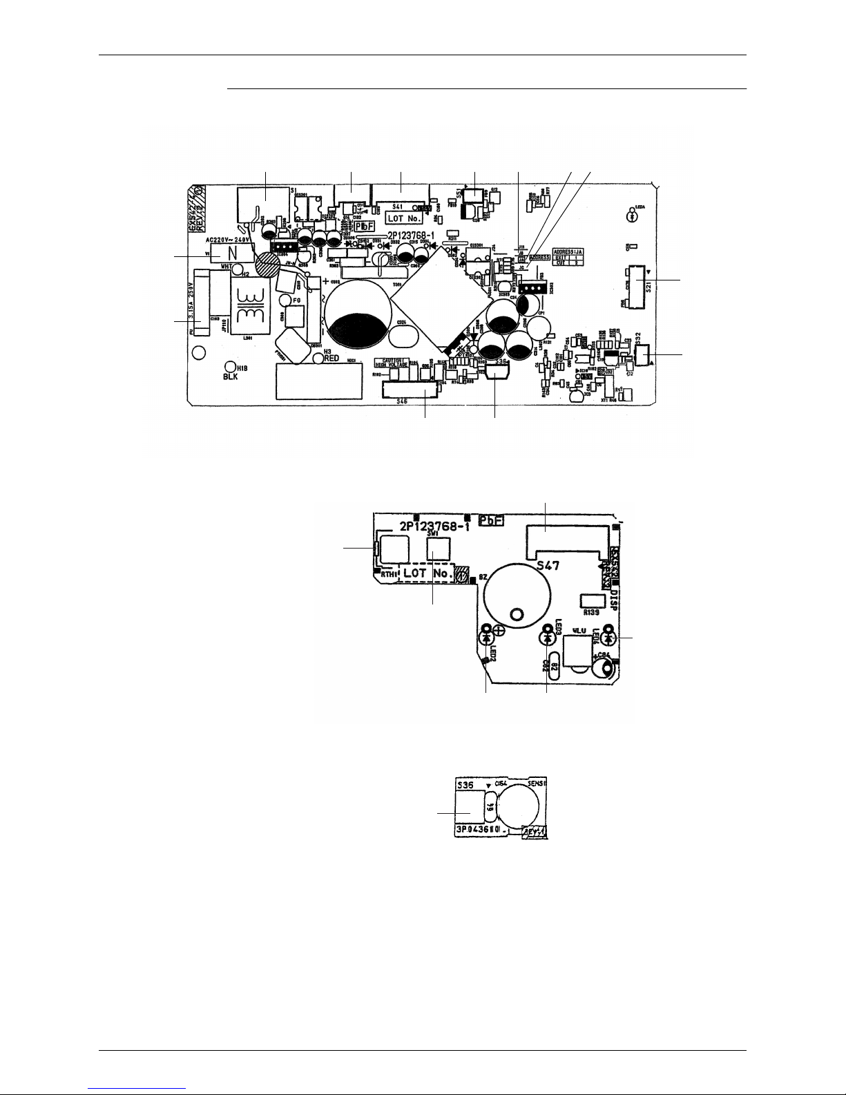
1.1 Indoor Unit
Connectors
Note: Other designations
1) S1 Connector for fan motor
2) S21 Connector for centralized control (HA)
3) S32 Connector for heat exchanger thermistor
4) S36 Connector for INTELLIGENT EYE sensor PCB and control
PCB
5) S41 Connector for swing motor
6) S46 Connector for signal receiver PCB
7) S47 Connector for control PCB
8) S49 Connector for reduction motor (front panel mechanism)
9) S51 Connector for front panel limit switch
1) V1 Varistor
2) JA Address setting jumper
JB Fan speed setting when compressor is OFF on thermostat
JC Power failure recovery function (auto-restart)
∗ Refer to page 175 for detail.
3) SW1 Forced operation ON / OFF switch
4) LED2 LED for INTELLIGENT EYE (green)
5) LED3 LED for timer (yellow)
6) LED4 LED for operation (green)
7) FU1 Fuse (3.15A)
8) RTH1 Room temperature thermistor
Si04-402A Printed Circuit Board Connector Wiring Diagram
Printed Circuit Board Connector Wiring Diagram 11
PCB Detail PCB(1): Control PCB (indoor unit)
PCB(2): Signal Receiver PCB
PCB(3): INTELLIGENT EYE sensor PCB
S21
V1
S46
FU1
S32
(R3319)
S1 S41 S51 JB JA JCS49
S36
LED4
RTH1
LED3
(R3320)
LED2
SW1
S47
S36
(R3321)

Printed Circuit Board Connector Wiring Diagram Si04-402A
12 Printed Circuit Board Connector Wiring Diagram
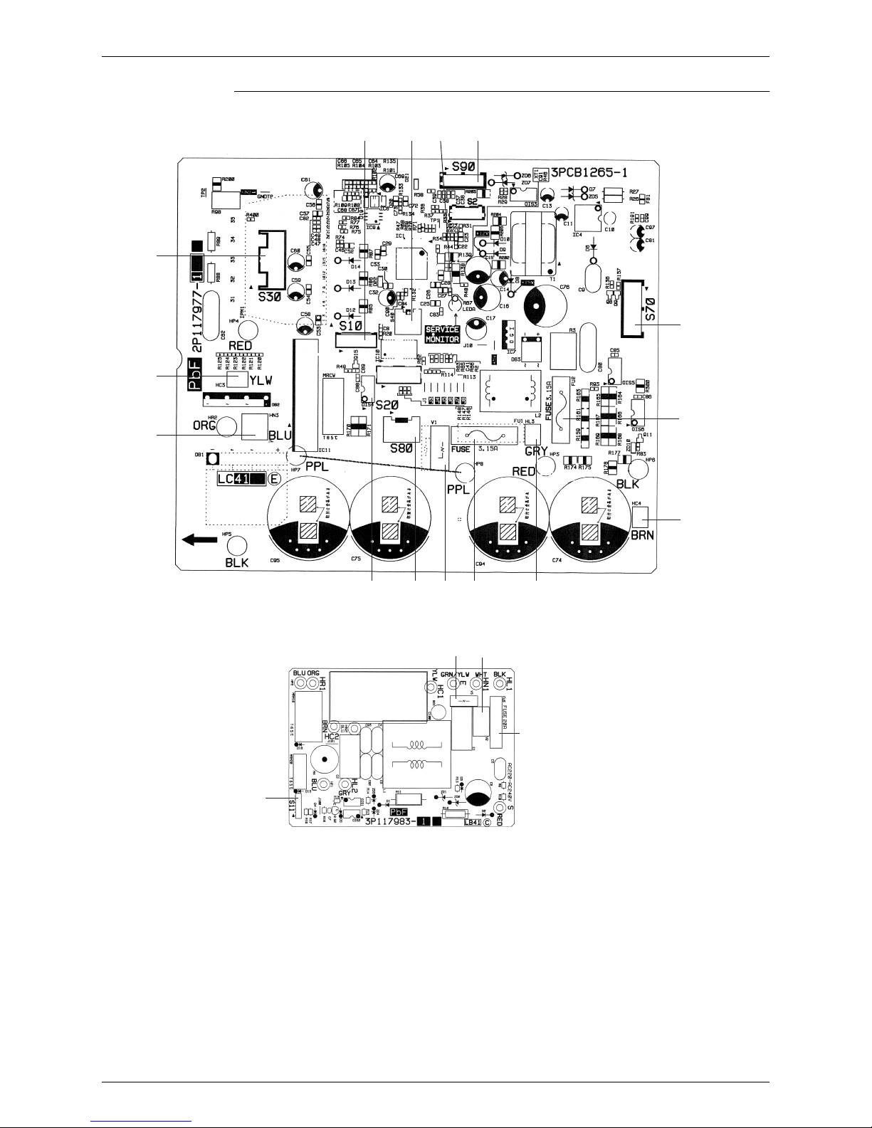
1.2 Outdoor Unit
Connectors
Note: Other Designations
1) S10 Connector for filter PCB
2) S11 Connector for control PCB
3) S20 Connector for electronic expansion valve coil
4) S30 Connector for compressor motor
5) S40 Connector for overload protector
6) S70 Connector for fan motor
7) S80 Connector for four way valve coil
8) S90 Connector for thermistors
(outdoor air, heat exchanger, discharge pipe)
9) HC3, HC4, HL3, HN3 Connector for filter PCB
1) FU1, FU2 Fuse (3.15A)
2) FU3 Fuse (20A)
3) LEDA Service monitor LED
4) V1, V2, V3 Varistor
Si04-402A Printed Circuit Board Connector Wiring Diagram
Printed Circuit Board Connector Wiring Diagram 13
PCB Detail PCB(1): Control PCB (outdoor unit)
PCB(2): Filter PCB
FU2(3.15A)
S30
HN3
HC3
S70
HC4
(R3322)
S40 LEDA S90
HL3FU1(3.15A)V1S80S20
S10
FU3(20A)
S11
(R3323)
V3
V2

Printed Circuit Board Connector Wiring Diagram Si04-402A
14 Printed Circuit Board Connector Wiring Diagram

Si04-402A
Function and Control 15
Part 4
Part 4Part 4
Part 4
Function and Control
Function and Control Function and Control
Function and Control
1. Main Functions......................................................................................16
1.1 Frequency Principle................................................................................16
1.2 Power-Airflow Flap, Wide-Angle Louvres and Auto-Swing ....................18
1.3 Operation Starting Control......................................................................19
1.4 Fan Speed Control for Indoor Units........................................................20
1.5 Programme Dry Function .......................................................................21
1.6 Automatic Operation...............................................................................22
1.7 NIGHT SET Mode ..................................................................................23
1.8 INTELLIGENT EYE ................................................................................24
1.9 Inverter Powerful Operation ...................................................................25
1.10 Other Functions......................................................................................26
2. Function of Thermistor ..........................................................................27
2.1 Heat Pump Model...................................................................................27
3. Control Specification .............................................................................28
3.1 Mode Hierarchy ......................................................................................28
3.2 Frequency Control..................................................................................29
3.3 Controls at Mode Changing / Start-up....................................................30
3.4 Discharge Pipe Control ..........................................................................32
3.5 Input Current Control ..............................................................................32
3.6 Freeze-up Protection Control .................................................................33
3.7 Heating Peak-cut Control .......................................................................33
3.8 Fan Control.............................................................................................34
3.9 Liquid Compression Protection Function 2.............................................34
3.10 Defrost Control .......................................................................................35
3.11 Electronic Expansion Valve Control .......................................................36
3.12 Malfunctions ...........................................................................................39
3.13 Forced Operation Mode .........................................................................40
3.14 Additional Function.................................................................................40

Main Functions Si04-402A
16 Function and Control
1. Main Functions
Note: See the list of functions for the functions applicable to different models.
1.1 Frequency Principle
Main Control
Parameters
The compressor is frequency-controlled during normal operation. The target frequency is set by
the following 2 parameters coming from the operating indoor unit:
The load condition of the operating indoor unit
The difference between the room temperature and the set temperature
Additional
Control
Parameters
The target frequency is adapted by additional parameters in the following cases:
Frequency restrictions
Initial settings
Forced cooling operation
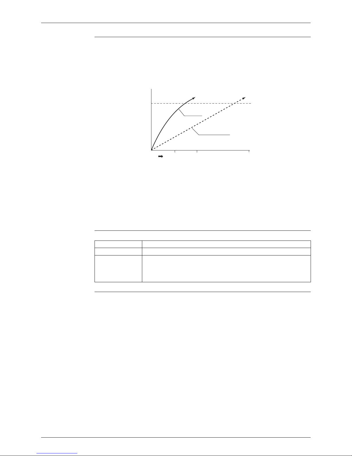
Inverter Principle To regulate the capacity, a frequency control is needed. The inverter makes it possible to vary
the rotation speed of the compressor. The following table explains the conversion principle:
Drawing of
Inverter
The following drawing shows a schematic view of the inverter principle:
Phase Description
1 The supplied AC power source is converted into the DC power source for the present.
2 The DC power source is reconverted into the three phase AC power source with variable
frequency.
When the frequency increases, the rotation speed of the compressor increases resulting
in an increased refrigerant circulation. This leads to a higher amount of the heat
exchange per unit.
When the frequency decreases, the rotation speed of the compressor decreases
resulting in a decreased refrigerant circulation. This leads to a lower amount of the heat
exchange per unit.
50 Hz
60 Hz
Refrigerant circulation rate (high)
Amount of heat
exchanged air (large)
Amount of heat
exchanged air (small)
AC
power
freq=
constant
DC
power
Amount of heat
exchanged air (large)
Amount of heat
exchanged air (small)
high f
low f
freq=variable
capacity=
variable
Refrigerant circulation rate (low)
high speed
low speed
(R2812)
Si04-402A Main Functions
Function and Control 17
Inverter Features The inverter provides the following features:
The regulating capacity can be changed according to the changes in the outside
temperature and cooling/heating load.
Quick heating and quick cooling
The compressor rotational speed is increased when starting the heating (or cooling). This
enables a quick set temperature.
Even during extreme cold weather, the high capacity is achieved. It is maintained even when
the outside temperature is 2°C.
Comfortable air conditioning
A detailed adjustment is integrated to ensure a fixed room temperature. It is possible to air
condition with a small room temperature variation.
Energy saving heating and cooling
Once the set temperature is reached, the energy saving operation enables to maintain the
room temperature at low power.
Frequency Limits The following table shows the functions that define the minimum and maximum frequency:
Forced Cooling
Operation
For more information, refer to “Forced operation mode” on page
40
.
60 120 300
45˚C
Air discharge
temperature
inverter
normal heat pump
Start
seconds
(R1187)
Frequency limits Limited during the activation of following functions
Low Four way valve operation compensation. Refer to page 31.
High Input current control. Refer to page 32.
Compressor protection function. Refer to page 31.
Heating peak-cut control. Refer to page 33.
Freeze-up protection control. Refer to page 33.
Defrost control. Refer to page 35.
Main Functions Si04-402A
18 Function and Control
1.2 Power-Airflow Flap, Wide-Angle Louvres and AutoSwing
Power-airflow
Flap
The large flap sends a large volume of air downwards to the floor. The flap provides an optimum
control area in cooling, heating and dry mode.
Heating Mode
During heating mode, the large flap enables direct warm air straight downwards. The flap
presses the warm air above the floor to reach the entire room.
Cooling Mode
During cooling mode, the flap retracts into the indoor unit. Then, cool air can be blown far and
pervaded all over the room.
Wide-Angle
Louvres
The louvres, made of elastic synthetic resin, provide a wide range of airflow that guarantees a
comfortable air distribution.
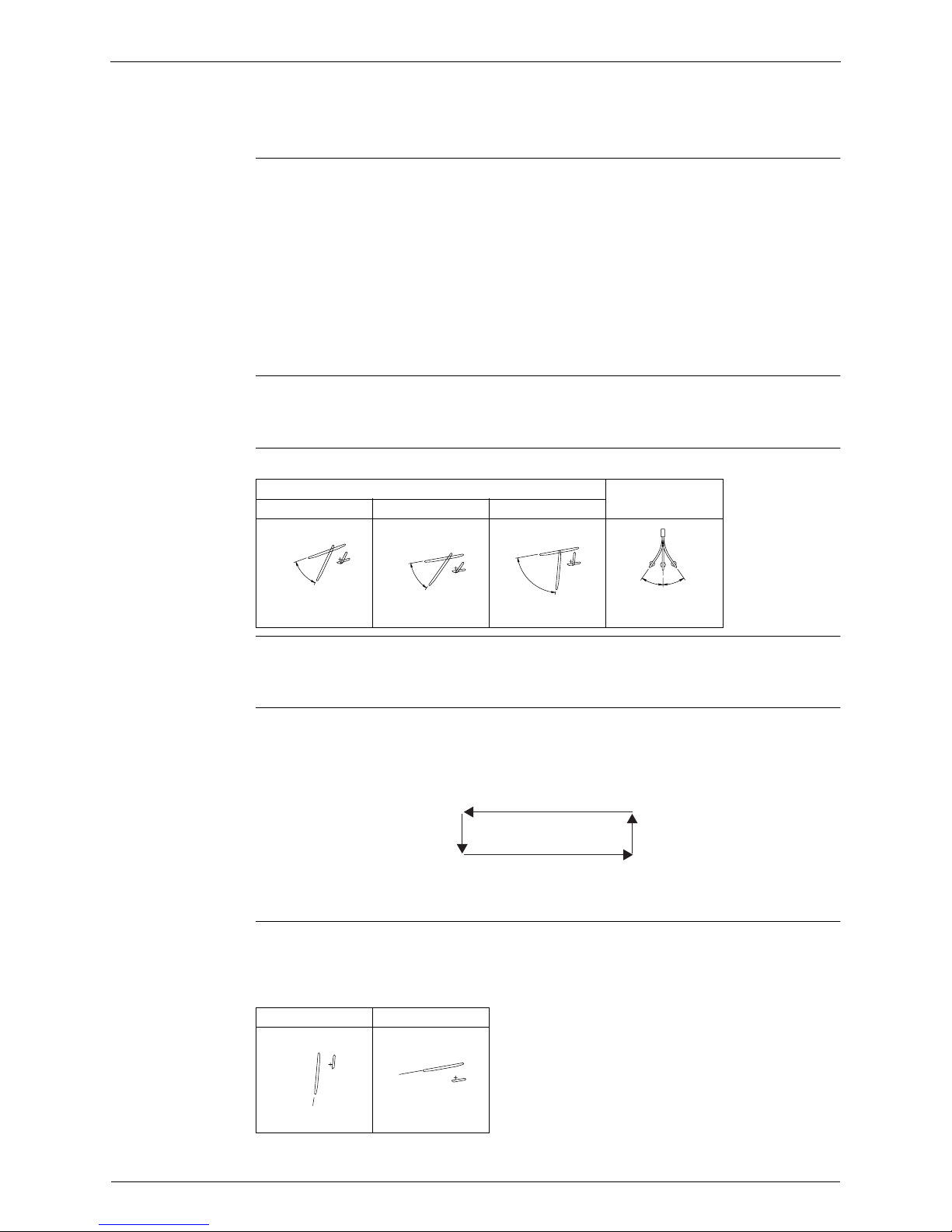
Auto-Swing The following table explains the auto-swing process for heating, cooling, dry and fan :
Outline of 3-D
Airflow
Alternative repetition of vertical and horizontal swing motions enables uniform air-conditioning of
the entire room. This function is effective for starting the air conditioner.
Detail of the
Action
When the horizontal swing and vertical swing are both set to auto mode, the airflow become 3-D
airflow and the horizontal swing and vertical swing motions are alternated. The order of swing
motion is such that it turns counterclockwise, starting from the right upper point as viewed to the
front side of the indoor unit.
COMFORT
AIRFLOW Mode
The vertical swing flap is controlled not to blow the air directly on the person in the room.
The airflow rate is set to AUTOMATIC.
The airflow rate has the upper limit (M tap) in heating mode.
The latest command has the priority between POWERFUL and COMFORT AIRFLOW.
Vertical Swing (up and down)
Horizontal Swing
(right and left)
Heating Cooling, Dry Fan
(R3293)
30˚
75˚
(R3294)
10˚
40˚
(R3295)
5˚
80˚
(R3296)
35˚
35˚
(R1024)
Heating Cooling, Dry
(R3297)
80˚
(R3298)
5˚
Si04-402A Main Functions
Function and Control 19
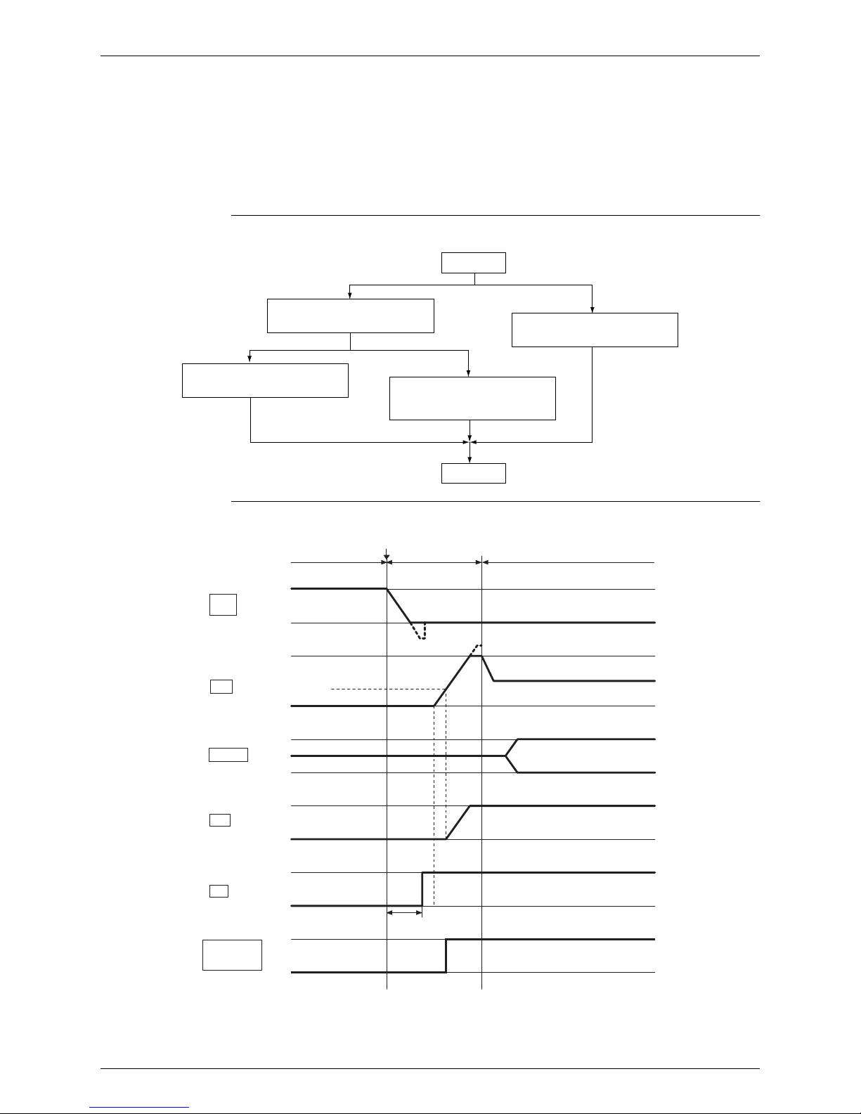
1.3 Operation Starting Control
The system carries out the following control at the beginning to conduct every functional parts
properly.
1. Opening the front panel fully
2. Output of the ∆D signal after the front panel starts moving
3. Opening the flap fully after the front panel opens fully
4. Making the fan rotate when the flap passes over the fan-banned area
Control Flow
Timing Chart
Opening the front panel
fully
Start
Running
Output of the ∆D signal after
the front panel starts moving
Making the fan rotate when
the flap passes over the
fan-banned area
Opening the flap fully
(R3311)
TDELTA
Fully close
OFF
Start
ON
Front
panel
Flap
Under running control
Under running control
Under operation mode control
Under operation mode control
The outdoor unit provides force
when it receives the ∆D signal.
Louvers
Fan
Force supply
(from the
outdoor unit)
∆D
Fully open
Fully open
Fully close
Right
Left
ON
OFF
OFF
Output
ON
∆0
Fan-banned area
Operation
starting control
(R3312)
Main Functions Si04-402A
20 Function and Control
1.4 Fan Speed Control for Indoor Units
Control Mode The airflow rate can be automatically controlled depending on the difference between the set
temperature and the room temperature. This is done through phase control and hall IC control.
For more information about Hall IC, refer to the troubleshooting for fan motor on page 77.
Phase Steps Phase control and fan speed control contains 9 steps: LLL, LL, SL, L, ML, M, MH, H and HH.
= Within this range the airflow rate is automatically controlled when the FAN setting
button is set to automatic.
Note: 1. During powerful operation, fan operates H tap + 50 - 70 rpm.
2. Fan stops during defrost operation.
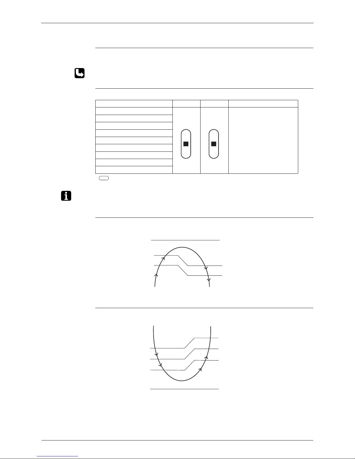
Automatic Air
Flow Control for
Heating
The following drawing explains the principle for fan speed control for heating:
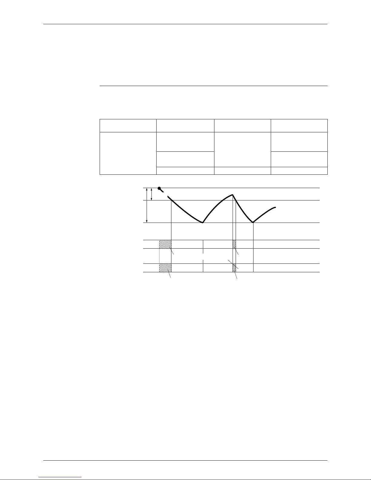
Automatic Air
Flow Control for
Cooling
The following drawing explains the principle of fan speed control for cooling:
Step Cooling Heating Dry mode
LLL (Heating thermostat OFF)
25/35kW class :
830 - 980 rpm
(During powerful operation :
1030 rpm)
LL (Cooling thermostat OFF)
SL (Silent)
L
ML
M
MH
H
HH (Powerful)
(R4085) (R4085)
-1.5˚C
0˚C
-0.5˚C
-2˚C
L
ML
M
Thermostat
setting
temperature
Phase control
Difference between room
and set temperature
fan speed
(R3299)
+1.5˚C
+2.5˚C
+0.5˚C
+2˚C
+3˚C
+1˚C
M
ML
MH
L
fan speed
Difference between room
and set temperature
Phase control
Thermostat
setting
temperature
(R3300)
Si04-402A Main Functions
Function and Control 21
1.5 Programme Dry Function
Programme dry function removes humidity while preventing the room temperature from
lowering.
Since the microcomputer controls both the temperature and air flow volume, the temperature
adjustment and fan adjustment buttons are inoperable in this mode.
In Case of
Inverter Units
The microcomputer automatically sets the temperature and fan settings. The difference
between the room temperature at startup and the temperature set by the microcomputer is
divided into two zones. Then, the unit operates in the dry mode with an appropriate capacity for
each zone to maintain the temperature and humidity at a comfortable level.
Room temperature at
startup
Temperature (ON point)
at which operation starts
Frequency switching
point
Temperature difference
for operation stop
24ºC
Room temperature at
startup
1.0ºC
2.5ºC
18ºC
18ºC2.0ºC
17ºC
—
1.0˚C
LHz LHz
*55Hz
*55Hz
LHz indicates low frequency. Item marked with varies depending on models.
ON point
OFF point
Compressor
control
Stop Stop
Stop Stop
Indoor unit fan
Extra-low air flow
Extra-low air flow
Low air flow
Low air flow
(R3301)
Frequency
switching
point
 Loading...