

Daikin CTXG50JV1BW, FTXS35G2V1B, FDXS25EAVMB, FLXS60BAVMB, BPMKS967B3B Service Manual
...
Service
Manual
E-Series
SiBE18-821_C
[Applied Models]
● Super Multi Plus : Heat Pump

SiBE18-821_C
i Table of Contents
SUPER MULTI PLUS
E-Series
zHeat Pump
Outdoor Unit
RMXS112E8V1B
RMXS140E8V1B
RMXS160E8V1B
BP Unit
BPMKS967B2B
BPMKS967B3B
Indoor Unit
FTXG25EV1BW(S) FTXS60FV1B FVXS25FV1B FFQ25B8V1B
FTXG35EV1BW(S) FTXS71FV1B FVXS35FV1B FFQ35B8V1B
CTXG50EV1BW(S) FTXS60GV1B FVXS50FV1B FFQ50B8V1B
FTXG25JV1BW(S) FTXS71GV1B FLXS25BAVMB FFQ60B8V1B
FTXG35JV1BW(S) FLXS35BAVMB FCQ35C7VEB
CTXG50JV1BW(S) FLXS50BAVMB FCQ50C7VEB
FTXS20G2V1B FLXS60BAVMB FCQ60C7VEB
FTXS25G2V1B FDXS25EAVMB FDBQ25B8V1
FTXS35G2V1B FDXS35EAVMB FBQ35C7VEB
FTXS42G2V1B FDXS50CVMB FBQ50C7VEB
FTXS50G2V1B FDXS60CVMB FBQ60C7VEB
FHQ35BVV1B
FHQ50BVV1B
FHQ60BVV1B

SiBE18-821_C
Table of Contents ii
1. Introduction ........................................................................................... vii
1.1 Safety Cautions ...................................................................................... vii
1.2 Used Icons .............................................................................................. xi
Part 1 List of Functions ................................................................1
1. Functions.................................................................................................2
Part 2 Specifications ..................................................................10
1. Specifications........................................................................................11
1.1 Outdoor Unit ...........................................................................................11
1.2 BP Unit ...................................................................................................12
1.3 Indoor Unit..............................................................................................13
Part 3 Printed Circuit Board Connector Wiring Diagram ...........26
1. Outdoor Unit..........................................................................................27
1.1 RMXS112/140/160E8V1B......................................................................27
2. BP Unit..................................................................................................30
2.1 BPMKS967B2B/B3B ..............................................................................30
3. Indoor Unit.............................................................................................31
3.1 Wall Mounted Type ................................................................................31
3.2 Floor Standing Type ...............................................................................44
3.3 Floor / Ceiling Suspended Dual Type.....................................................46
3.4 Duct Connected Type.............................................................................48
3.5 Ceiling Mounted Cassette Type .............................................................50
3.6 Ceiling Mounted Built-in Type ................................................................54
3.7 Ceiling Suspended Type ........................................................................59
4. Remote Controller.................................................................................61
4.1 Wired Remote Controller........................................................................61
4.2 Wireless Remote Controller ...................................................................63
Part 4 Refrigerant Circuit ...........................................................65
1. Refrigerant Circuit .................................................................................66
1.1 Outdoor Unit ...........................................................................................66
1.2 BP Unit ...................................................................................................68
2. Functional Parts Layout ........................................................................69
2.1 Outdoor Unit ...........................................................................................69
3. Refrigerant Flow for Each Operation Mode...........................................71
3.1 Cooling Operation ..................................................................................71
3.2 Heating Operation ..................................................................................72
3.3 Cooling Oil Return Operation .................................................................73
3.4 Heating Oil Return Operation & Defrost Operation ................................74
Part 5 Function............................................................................75
1. Operation Mode ....................................................................................77
2. Basic Control.........................................................................................78
2.1 Normal Operation ...................................................................................78
2.2 Compressor PI Control ...........................................................................79
2.3 Electronic Expansion Valve PI Control...................................................80

SiBE18-821_C
iii Table of Contents
2.4 Cooling Operation Fan Control...............................................................81
3. Special Control......................................................................................82
3.1 Startup Control .......................................................................................82
3.2 Oil Return Operation ..............................................................................83
3.3 Defrosting Operation ..............................................................................85
3.4 Pump-down Residual Operation ............................................................86
3.5 Restart Standby......................................................................................87
3.6 Stopping Operation ................................................................................87
4. Protection Control .................................................................................88
4.1 High Pressure Protection Control...........................................................88
4.2 Low Pressure Protection Control............................................................89
4.3 Discharge Pipe Temperature Protection Control....................................90
4.4 Inverter Protection Control .....................................................................91
4.5 Freeze-up Protection Control .................................................................92
4.6 Dew Condensation Prevention Control ..................................................93
5. Other Control.........................................................................................94
5.1 Demand Control .....................................................................................94
5.2 Heating Operation Prohibition Control....................................................94
6. BP Unit Control .....................................................................................95
6.1 BP Unit Command Conversion ..............................................................95
6.2 BP Unit Electronic Expansion Valve Control ..........................................96
6.3 SH Control in Cooling Operation ............................................................98
6.4 SC Control in Heating Operation............................................................99
6.5 Heat Exchanger Isothermal Control in Heating Operation .....................99
7. Indoor Unit Control (RA Models) .........................................................100
7.1 Temperature Control ............................................................................100
7.2 Operation Starting Control....................................................................101
7.3 Airflow Direction Control.......................................................................102
7.4 Fan Speed Control for Indoor Units......................................................104
7.5 Program Dry Operation ........................................................................105
7.6 Automatic Operation.............................................................................106
7.7 Thermostat Control...............................................................................107
7.8 NIGHT SET Mode ................................................................................109
7.9 ECONO Operation ...............................................................................110
7.10 HOME LEAVE Operation .....................................................................111
7.11 2-Area INTELLIGENT EYE Operation .................................................112
7.12 INTELLIGENT EYE Operation .............................................................114
7.13 Inverter POWERFUL Operation ...........................................................115
7.14 Other Functions....................................................................................117
8. Indoor Unit Control (SA Models) .........................................................119
8.1 Drain Pump Control ..............................................................................119
8.2 Thermostat Sensor in Remote Controller.............................................121
8.3 Freeze Prevention Control ...................................................................123
8.4 Hot Start Control (In Heating Operation Only)......................................124
Part 6 Test Operation and Field Settings.................................125
1. Test Operation ....................................................................................126
1.1 Procedure and Outline .........................................................................126
1.2 Operation when Power is Turned On ...................................................128
1.3 Outdoor Unit PCB Layout .....................................................................129
1.4 BP Unit .................................................................................................130

SiBE18-821_C
Table of Contents iv
1.5 RA Indoor Unit - F(C)TXG, FTXS, FVXS, FLXS, FDXS Series............132
1.6 SA Indoor Unit - FFQ, FCQ, FDBQ, FBQ, FHQ Series........................134
2. Field Settings ......................................................................................136
2.1 Outdoor Unit .........................................................................................136
2.2 RA Indoor Unit - F(C)TXG, FTXS, FVXS, FLXS, FDXS Series............154
2.3 SA Indoor Unit - FFQ, FCQ, FDBQ, FBQ, FHQ Series........................158
Part 7 Operation Manual ...........................................................166
1. System Configuration..........................................................................167
2. Outdoor Unit........................................................................................168
2.1 RMXS Series........................................................................................168
3. RA Indoor Unit.....................................................................................169
3.1 FTXG-J, CTXG-J Series - ARC466A1 .................................................169
3.2 FTXS-G, FVXS Series - ARC452A1, A3 ..............................................192
3.3 FTXG-E, CTXG-E, FTXS-F, FLXS, FDXS Series -
ARC433B41, B67, B69, B70 ................................................................227
4. SA Indoor Unit - FFQ, FCQ, FDBQ, FBQ, FHQ Series.......................251
4.1 BRC1D528 ...........................................................................................251
4.2 BRC1E51A7 .........................................................................................266
4.3 BRC7E530W, BRC7F532F, BRC7EA63W ..........................................311
Part 8 Troubleshooting ............................................................. 323
1. Troubleshooting with LED...................................................................325
1.1 Outdoor Unit .........................................................................................325
1.2 BP Unit .................................................................................................330
1.3 Indoor Unit............................................................................................331
2. Service Check Function ......................................................................334
2.1 RA Indoor Unit - F(C)TXG, FTXS, FVXS, FLXS, FDXS Series............334
2.2 SA Indoor Unit - FFQ, FCQ, FDBQ, FBQ, FHQ Series........................343
3. Error Codes and Description...............................................................350
4. Troubleshooting for RA Indoor Unit.....................................................352
4.1 Indoor Unit PCB Abnormality ...............................................................352
4.2 Freeze-up Protection Control or Heating Peak-cut Control..................353
4.3 Fan Motor or Related Abnormality .......................................................355
4.4 Thermistor or Related Abnormality (Indoor Unit)..................................358
4.5 Front Panel Open / Close Fault ............................................................359
4.6 Check for RA Indoor Unit .....................................................................360
5. Troubleshooting for SA Indoor Unit.....................................................363
5.1 Indoor Unit PCB Abnormality ...............................................................363
5.2 Drain Water Level System Abnormality................................................364
5.3 Fan Motor or Related Abnormality (FHQ Series) .................................366
5.4 Swing Motor Lock (FHQ Series)...........................................................367
5.5 Drain System Abnormality ....................................................................368
5.6 Indoor Liquid Pipe Thermistor (R2T) Abnormality ................................369
5.7 Indoor Heat Exchanger Thermistor (R3T) Abnormality ........................370
5.8 Suction Air Thermistor (R1T) Abnormality............................................371
5.9 Remote Controller Thermistor Abnormality ..........................................372
5.10 Transmission Error between Remote Controller and Indoor Unit.........373
5.11 Transmission Error between Main and Sub Remote Controllers .........374
5.12 Field Setting Switch Abnormality..........................................................375

SiBE18-821_C
v Table of Contents
6. Troubleshooting for BP Unit................................................................376
6.1 Electronic Expansion Valve Abnormality ..............................................376
6.2 BP Unit PCB Abnormality.....................................................................377
6.3 BP Liquid or Gas Pipe Thermistor Abnormality ....................................378
6.4 Transmission Error between Indoor Unit and BP Unit..........................379
6.5 Transmission Error between Outdoor Unit and BP Unit.......................381
6.6 Check for BP Unit.................................................................................382
7. Troubleshooting for Outdoor Unit........................................................383
7.1 Outdoor Unit PCB Abnormality.............................................................383
7.2 Actuation of High Pressure Switch .......................................................384
7.3 Actuation of Low Pressure Sensor .......................................................386
7.4 Compressor Motor Lock .......................................................................388
7.5 Outdoor Fan Motor Abnormality ...........................................................389
7.6 Moving Part of Electronic Expansion Valve (Y1E, Y3E) Abnormality...390
7.7 Discharge Pipe Temperature Abnormality ...........................................392
7.8 Refrigerant Overcharged......................................................................393
7.9 Outdoor Temperature Thermistor (R1T) Abnormality ..........................394
7.10 Discharge Pipe Thermistor (R2T) Abnormality.....................................395
7.11 Suction Pipe Thermistor (R3T, R5T) Abnormality ................................396
7.12 Outdoor Heat Exchanger Thermistor (R4T) Abnormality .....................397
7.13 Outdoor Liquid Pipe Thermistor (R7T) Abnormality .............................398
7.14 Subcooling Heat Exchanger Gas Pipe Thermistor (R6T)
Abnormality ..........................................................................................399
7.15 High Pressure Sensor Abnormality ......................................................400
7.16 Low Pressure Sensor Abnormality .......................................................401
7.17 Outdoor Unit PCB Abnormality.............................................................402
7.18 Radiation Fin Temperature Rise ..........................................................403
7.19 Inverter Compressor Abnormality.........................................................404
7.20 Inverter Current Abnormality ................................................................405
7.21 Compressor Start-up Error ...................................................................406
7.22 High Voltage of Capacitor in Main Inverter Circuit ...............................407
7.23 Radiation Fin Thermistor Abnormality ..................................................408
7.24 Low Pressure Drop due to Refrigerant Shortage or
Electronic Expansion Valve Abnormality ..............................................409
7.25 Power Supply Insufficient or Instantaneous Failure .............................411
7.26 Check Operation is not Conducted ......................................................412
7.27 Transmission Error between Remote Controller and Indoor Unit.........413
7.28 Transmission Error between Main and Sub Remote Controllers .........414
7.29 Transmission Error Between Indoor Unit and
Outdoor Unit in the Same System........................................................415
7.30 Excessive Number of Indoor Units .......................................................417
7.31 Address Duplication of Central Remote Controller...............................418
7.32 Transmission Error between Centralized Remote Controller and
Indoor Unit............................................................................................419
7.33 System is not Set yet............................................................................421
7.34 System Abnormality, Refrigerant System Address Undefined .............422
7.35 Check for Outdoor Unit.........................................................................423
8. Thermistor Resistance / Temperature Characteristics........................427
9. Pressure Sensor .................................................................................429
10.Method of Replacing Inverter’s Power Transistors Modules...............430

SiBE18-821_C
Table of Contents vi
Part 9 Removal Procedure ........................................................432
1. Outdoor Unit........................................................................................433
1.1 Removal of Outer Panels .....................................................................433
1.2 Removal of PCBs / Electrical Components ..........................................436
1.3 Removal of Outdoor Fans / Fan Motors ...............................................443
1.4 Removal of Thermistors .......................................................................445
1.5 Removal of Electronic Expansion Valves / Peripheral Equipments .....446
1.6 Removal of Four Way Valve.................................................................450
1.7 Removal of Compressor.......................................................................451
2. BP Unit................................................................................................454
2.1 Removal of PCB Assembly ..................................................................454
2.2 Removal of Electronic Expansion Valve Coils......................................457
Part 10Appendix.........................................................................460
1. Piping Diagrams..................................................................................461
1.1 Outdoor Unit .........................................................................................461
1.2 BP Unit .................................................................................................462
1.3 Indoor Unit............................................................................................463
2. Wiring Diagrams..................................................................................469
2.1 Outdoor Unit .........................................................................................469
2.2 BP Unit .................................................................................................470
2.3 Indoor Unit............................................................................................471
Introduction SiBE18-821_C
vii
1. Introduction
1.1 Safety Cautions
Cautions and
Warnings
Be sure to read the following safety cautions before conducting repair work.
The caution items are classified into “ Warning” and “ Caution”. The “ Warning”
items are especially important since they can lead to death or serious injury if they are not
followed closely. The “ Caution” items can also lead to serious accidents under some
conditions if they are not followed. Therefore, be sure to observe all the safety caution items
described below.
About the pictograms
This symbol indicates the item for which caution must be exercised.
The pictogram shows the item to which attention must be paid.
This symbol indicates the prohibited action.
The prohibited item or action is shown in the illustration or near the symbol.
This symbol indicates the action that must be taken, or the instruction.
The instruction is shown in the illustration or near the symbol.
After the repair work is complete, be sure to conduct a test operation to ensure that the
equipment operates normally, and explain the cautions for operating the product to the
customer.
1.1.1 Cautions Regarding Safety of Workers
Warning
Be sure to disconnect the power cable plug from the plug socket before
disassembling the equipment for repair.
Working on the equipment that is connected to the power supply may cause an
electrical shock.
If it is necessary to supply power to the equipment to conduct the repair or
inspecting the circuits, do not touch any electrically charged sections of the
equipment.
If the refrigerant gas is discharged during the repair work, do not touch the
discharged refrigerant gas.
The refrigerant gas may cause frostbite.
When disconnecting the suction or discharge pipe of the compressor at the
welded section, evacuate the refrigerant gas completely at a well-ventilated
place first.
If there is a gas remaining inside the compressor, the refrigerant gas or
refrigerating machine oil discharges when the pipe is disconnected, and it may
cause injury.
If the refrigerant gas leaks during the repair work, ventilate the area. The
refrigerant gas may generate toxic gases when it contacts flames.
The step-up capacitor supplies high-voltage electricity to the electrical
components of the outdoor unit.
Be sure to discharge the capacitor completely before conducting repair work.
A charged capacitor may cause an electrical shock.
Do not start or stop the air conditioner operation by plugging or unplugging the
power cable plug.
Plugging or unplugging the power cable plug to operate the equipment may
cause an electrical shock or fire.
SiBE18-821_C Introduction
viii
Be sure to wear a safety helmet, gloves, and a safety belt when working at a
high place (more than 2 m). Insufficient safety measures may cause a fall
accident.
In case of R-410A refrigerant models, be sure to use pipes, flare nuts and tools
for the exclusive use of the R-410A refrigerant.
The use of materials for R-22 refrigerant models may cause a serious accident
such as a damage of refrigerant cycle as well as an equipment failure.
Warning
Caution
Do not repair the electrical components with wet hands.
Working on the equipment with wet hands may cause an electrical shock.
Do not clean the air conditioner by splashing water.
Washing the unit with water may cause an electrical shock.
Be sure to provide the grounding when repairing the equipment in a humid or
wet place, to avoid electrical shocks.
Be sure to turn off the power switch and unplug the power cable when cleaning
the equipment.
The internal fan rotates at a high speed, and cause injury.
Be sure to conduct repair work with appropriate tools.
The use of inappropriate tools may cause injury.
Be sure to check that the refrigerating cycle section has cooled down enough
before conducting repair work.
Working on the unit when the refrigerating cycle section is hot may cause
burns.
Use the welder in a well-ventilated place.
Using the welder in an enclosed room may cause oxygen deficiency.

Introduction SiBE18-821_C
ix
1.1.2 Cautions Regarding Safety of Users
Warning
Be sure to use parts listed in the service parts list of the applicable model and
appropriate tools to conduct repair work. Never attempt to modify the
equipment.
The use of inappropriate parts or tools may cause an electrical shock,
excessive heat generation or fire.
If the power cable and lead wires have scratches or deteriorated, be sure to
replace them.
Damaged cable and wires may cause an electrical shock, excessive heat
generation or fire.
Do not use a joined power cable or extension cable, or share the same power
outlet with other electrical appliances, since it may cause an electrical shock,
excessive heat generation or fire.
Be sure to use an exclusive power circuit for the equipment, and follow the local
technical standards related to the electrical equipment, the internal wiring
regulations, and the instruction manual for installation when conducting
electrical work.
Insufficient power circuit capacity and improper electrical work may cause an
electrical shock or fire.
Be sure to use the specified cable for wiring between the indoor and outdoor
units. Make the connections securely and route the cable properly so that there
is no force pulling the cable at the connection terminals.
Improper connections may cause excessive heat generation or fire.
When wiring between the indoor and outdoor units, make sure that the terminal
cover does not lift off or dismount because of the cable.
If the cover is not mounted properly, the terminal connection section may cause
an electrical shock, excessive heat generation or fire.
Do not damage or modify the power cable.
Damaged or modified power cable may cause an electrical shock or fire.
Placing heavy items on the power cable, and heating or pulling the power cable
may damage the cable.
Do not mix air or gas other than the specified refrigerant (R-410A / R-22) in the
refrigerant system.
If air enters the refrigerating system, an excessively high pressure results,
causing equipment damage and injury.
If the refrigerant gas leaks, be sure to locate the leaking point and repair it
before charging the refrigerant. After charging refrigerant, make sure that there
is no refrigerant leak.
If the leaking point cannot be located and the repair work must be stopped, be
sure to perform pump-down and close the service valve, to prevent the
refrigerant gas from leaking into the room. The refrigerant gas itself is
harmless, but it may generate toxic gases when it contacts flames, such as fan
and other heaters, stoves and ranges.
When relocating the equipment, make sure that the new installation site has
sufficient strength to withstand the weight of the equipment.
If the installation site does not have sufficient strength and if the installation
work is not conducted securely, the equipment may fall and cause injury.
SiBE18-821_C Introduction
x
Check to make sure that the power cable plug is not dirty or loose, then insert
the plug into a power outlet securely.
If the plug has dust or loose connection, it may cause an electrical shock or fire.
Be sure to install the product correctly by using the provided standard
installation frame.
Incorrect use of the installation frame and improper installation may cause the
equipment to fall, resulting in injury.
For unitary type
only
Be sure to install the product securely in the installation frame mounted on the
window frame.
If the unit is not securely mounted, it may fall and cause injury.
For unitary type
only
When replacing the coin battery in the remote controller, be sure to disposed
of the old battery to prevent children from swallowing it.
If a child swallows the coin battery, see a doctor immediately.
Warning
Caution
Installation of a leakage breaker is necessary in some cases depending on the
conditions of the installation site, to prevent electrical shocks.
Do not install the equipment in a place where there is a possibility of
combustible gas leaks.
If the combustible gas leaks and remains around the unit, it may cause a fire.
Check to see if the parts and wires are mounted and connected properly, and
if the connections at the soldered or crimped terminals are secure.
Improper installation and connections may cause excessive heat generation,
fire or an electrical shock.
If the installation platform or frame has corroded, replace it.
Corroded installation platform or frame may cause the unit to fall, resulting in
injury.
Check the grounding, and repair it if the equipment is not properly grounded.
Improper grounding may cause an electrical shock.
Introduction SiBE18-821_C
xi
1.2 Used Icons
Icons are used to attract the attention of the reader to specific information. The meaning of each
icon is described in the table below:
Be sure to measure the insulation resistance after the repair, and make sure
that the resistance is 1 MΩ or higher.
Faulty insulation may cause an electrical shock.
Be sure to check the drainage of the indoor unit after the repair.
Faulty drainage may cause the water to enter the room and wet the furniture
and floor.
Do not tilt the unit when removing it.
The water inside the unit may spill and wet the furniture and floor.
Be sure to install the packing and seal on the installation frame properly.
If the packing and seal are not installed properly, water may enter the room and
wet the furniture and floor.
For unitary type
only
Caution
Icon Type of
Information
Description
Note:
Note A “note” provides information that is not indispensable, but may
nevertheless be valuable to the reader, such as tips and tricks.
Caution
Caution A “caution” is used when there is danger that the reader, through
incorrect manipulation, may damage equipment, loose data, get
an unexpected result or has to restart (part of) a procedure.
Warning
Warning A “warning” is used when there is danger of personal injury.
Reference A “reference” guides the reader to other places in this binder or
in this manual, where he/she will find additional information on a
specific topic.

SiBE18-821_C
List of Functions 1
Part 1
List of Functions
1. Functions.................................................................................................2

Functions SiBE18-821_C
2 List of Functions
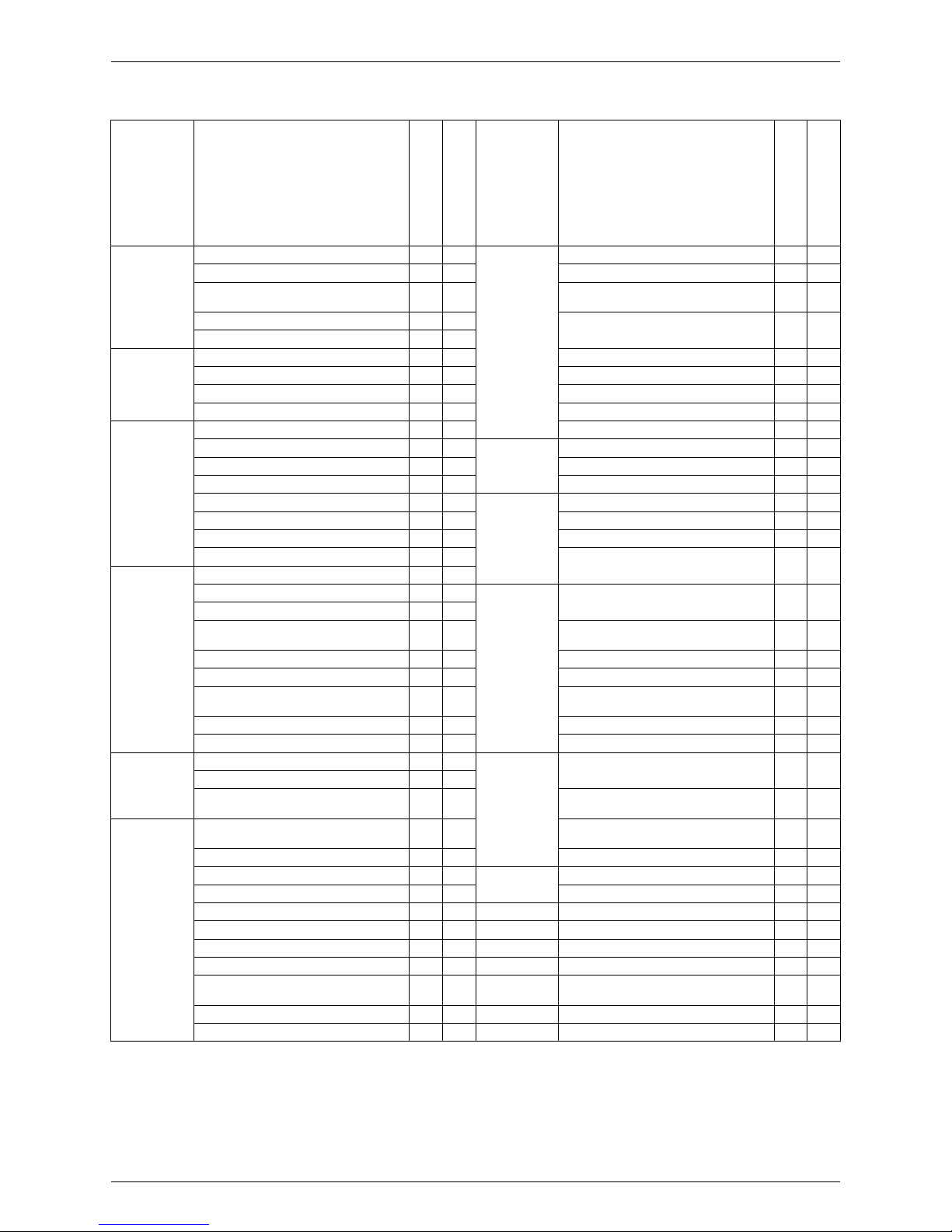
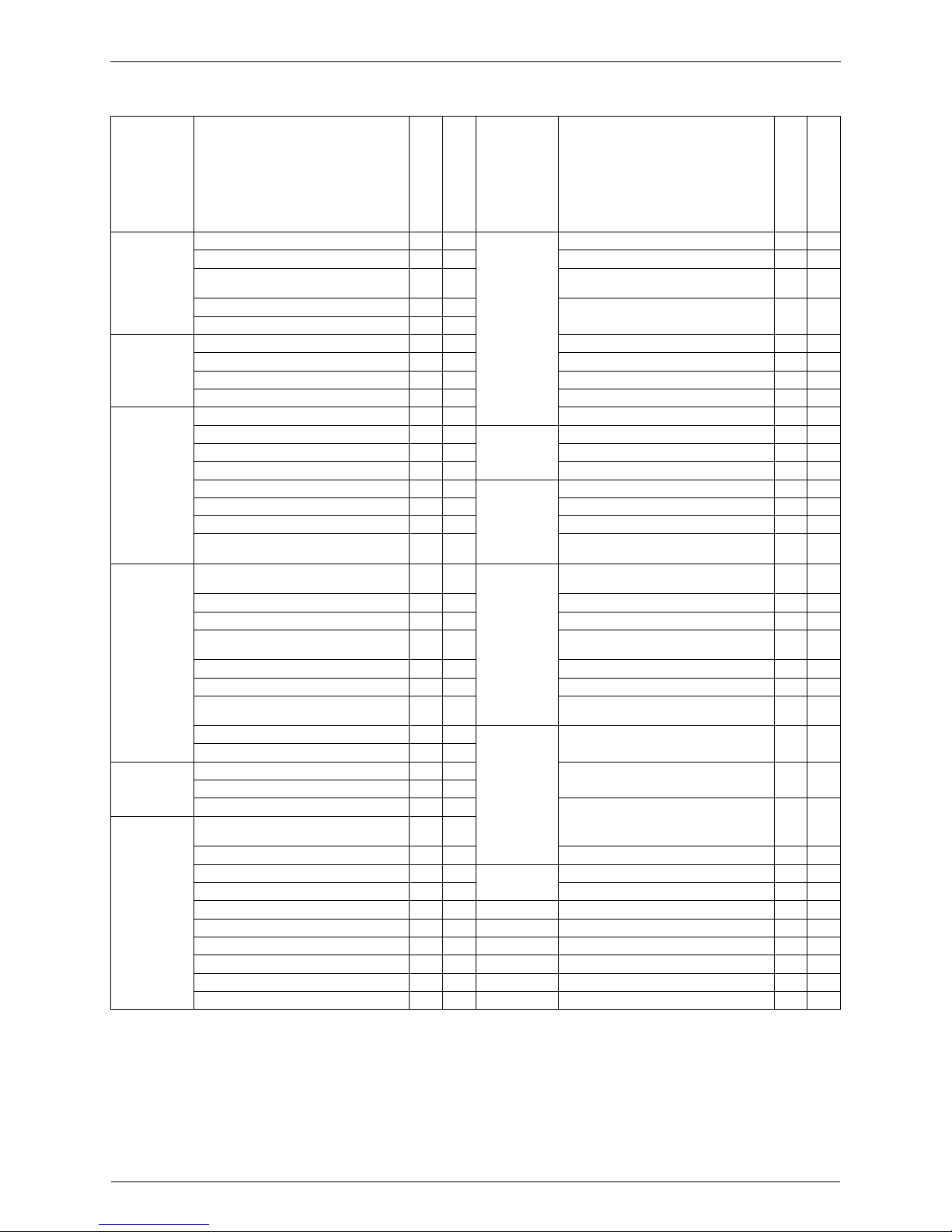
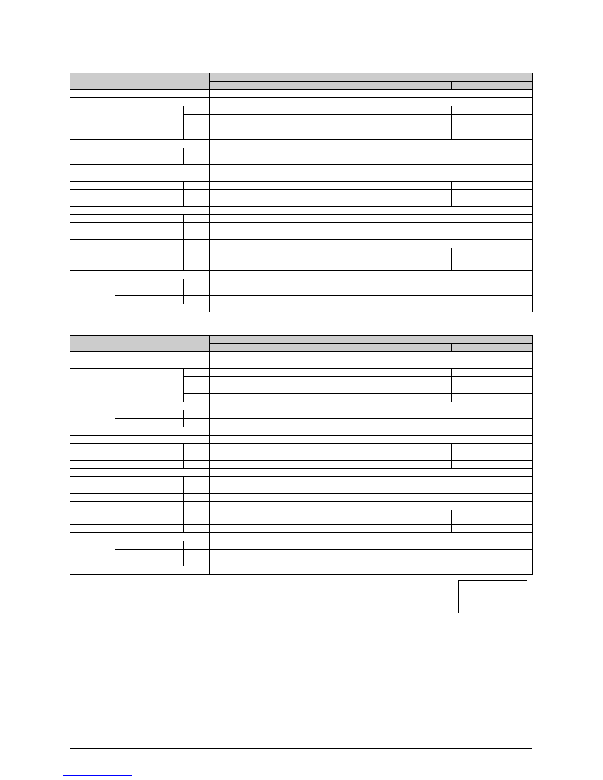
1. Functions
Category Functions
RMXS112/140/160E8V1B
Category Functions
RMXS112/140/160E8V1B
Basic
Function
Inverter (with Inverter Power Control)
{
Health &
Clean
Air-Purifying Filter —
Operation Limit for Cooling (°CDB)
–
5
~46
Photocatalytic Deodorizing Filter —
Operation Limit for Heating (°CWB)
–
15
~15.5
Air-Purifying Filter with Photocatalytic
Deodorizing Function
—
PAM Control —
Titanium Apatite Photocatalytic
Air-Purifying Filter
—
Standby Electricity Saving —
Compressor Oval Scroll Compressor
{
Air Filter (Prefilter) —
Swing Compressor — Wipe-Clean Flat Panel —
Rotary Compressor — Washable Grille —
Reluctance DC Motor
{
MOLD PROOF Operation —
Comfortable
Airflow
Power-Airflow Flap — Good-Sleep Cooling Operation —
Power-Airflow Dual Flaps — Timer WEEKLY TIMER Operation —
Power-Airflow Diffuser — 24-Hour ON/OFF TIMER —
Wide-Angle Louvers — NIGHT SET Mode —
Vertical Auto-Swing (Up and Down) — Worry Free
“Reliability &
Durability”
Auto-Restart (after Power Failure) —
Horizontal Auto-Swing (Right and Left) — Self-Diagnosis (Digital, LED) Display
{
3-D Airflow — Wiring Error Check Function
{
COMFORT AIRFLOW Operation — Automatic Test Operation
{
Comfort
Control
Auto Fan Speed — Memory Function
{
Indoor Unit Quiet Operation —
Anti-Corrosion Treatment of Outdoor Heat
Exchanger
{
NIGHT QUIET Mode (Automatic)
{
Flexibility Multi-Split / Split Type Compatible Indoor Unit —
OUTDOOR UNIT QUIET Operation (Manual)
{
H/P, C/O Compatible Indoor Unit —
2-Area INTELLIGENT EYE Operation — Flexible Power Supply Correspondence —
INTELLIGENT EYE Operation — High Ceiling Application —
Quick Warming Function
(Preheating Operation)
{
Chargeless —
Hot-Start Function — Either Side Drain (Right or Left) —
Automatic Defrosting
{
Power Selection —
Operation Automatic Operation — Remote
Control
5-Room Centralized Controller (Option) —
Program Dry Operation —
Fan Only —
Remote Control Adaptor
(Normal Open Pulse Contact) (Option)
—
Lifestyle
Convenience
New POWERFUL Operation
(Non-Inverter)
—
Inverter POWERFUL Operation —
Remote Control Adaptor
(Normal Open Contact) (Option)
—
Priority-Room Setting —
COOL / HEAT Mode Lock
{
DIII-NET Compatible (Adaptor) (Option) —
HOME LEAVE Operation — Remote
Controller
Wireless —
ECONO Operation — Wired —
Indoor Unit ON/OFF Button —
Signal Receiving Sign —
R/C with Back Light —
Temperature Display —
Note:
{
: Holding Functions
— : No Functions
SiBE18-821_C Functions
List of Functions 3
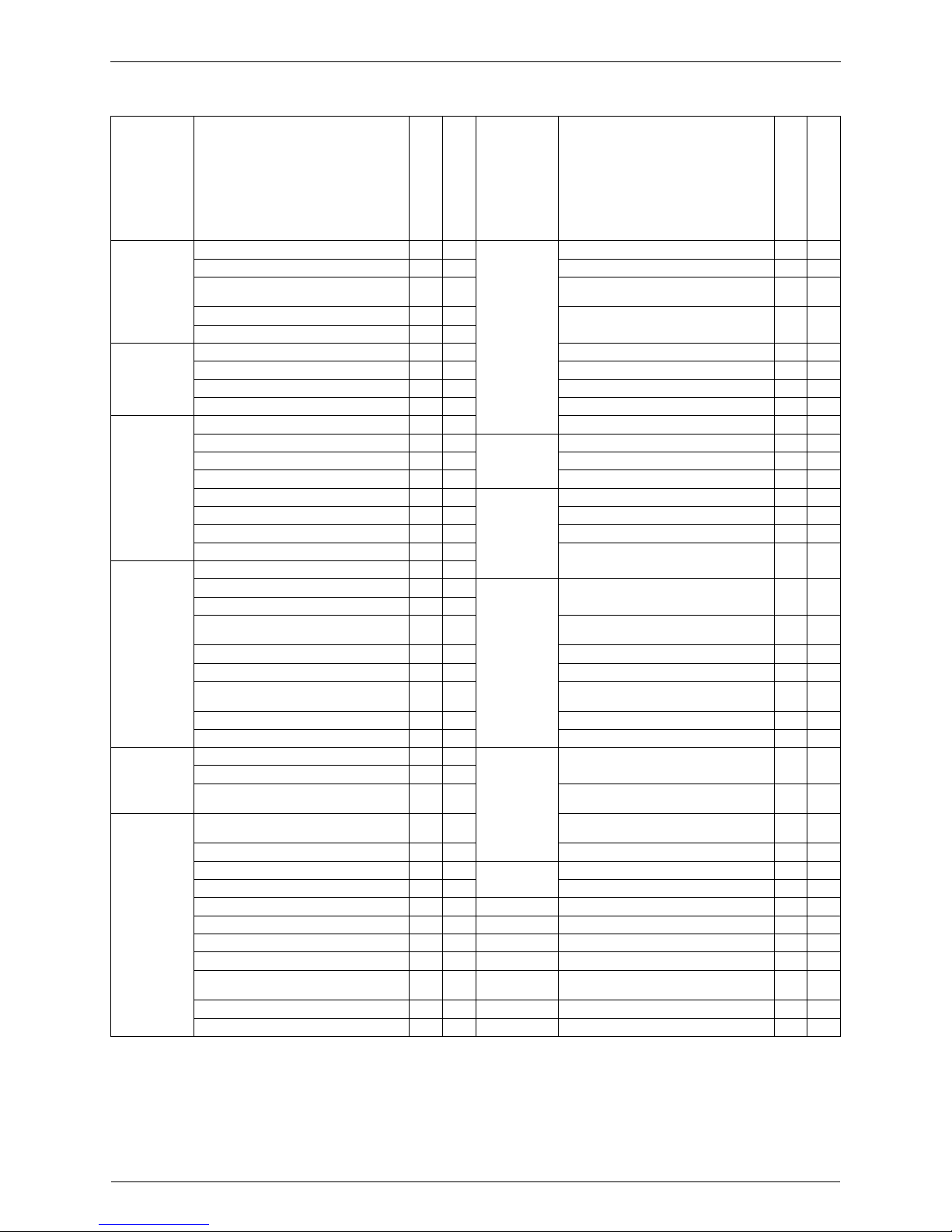
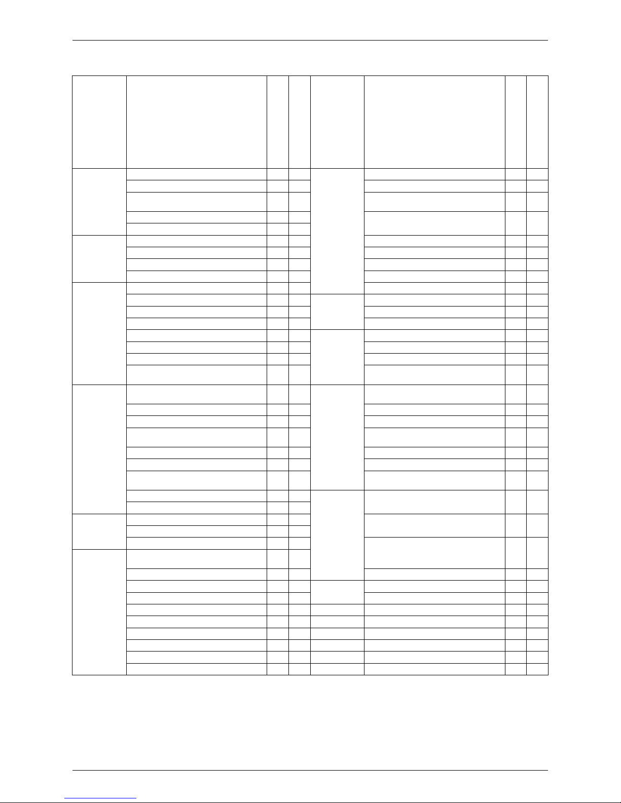
Category Functions
FTXG25/35EV1BW(S)
CTXG50EV1BW(S)
Category Functions
FTXG25/35EV1BW(S)
CTXG50EV1BW(S)
Basic
Function
Inverter (with Inverter Power Control)
{{
Health &
Clean
Air-Purifying Filter — —
Operation Limit for Cooling (°CDB) — — Photocatalytic Deodorizing Filter — —
Operation Limit for Heating (°CWB) — —
Air-Purifying Filter with Photocatalytic
Deodorizing Function
——
PAM Control — —
Titanium Apatite Photocatalytic
Air-Purifying Filter
{{
Standby Electricity Saving — —
Compressor Oval Scroll Compressor — — Air Filter (Prefilter)
{{
Swing Compressor — — Wipe-Clean Flat Panel
{{
Rotary Compressor — — Washable Grille — —
Reluctance DC Motor — — MOLD PROOF Operation — —
Comfortable
Airflow
Power-Airflow Flap — — Good-Sleep Cooling Operation — —
Power-Airflow Dual Flaps
{{
Timer WEEKLY TIMER Operation — —
Power-Airflow Diffuser — — 24-Hour ON/OFF TIMER
{{
Wide-Angle Louvers
{{
NIGHT SET Mode
{{
Vertical Auto-Swing (Up and Down)
{{
Worry Free
“Reliability &
Durability”
Auto-Restart (after Power Failure)
{{
Horizontal Auto-Swing (Right and Left)
{{
Self-Diagnosis (Digital, LED) Display
{{
3-D Airflow
{{
Wiring Error Check Function — —
COMFORT AIRFLOW Operation
{{
Anti-Corrosion Treatment of Outdoor
Heat Exchanger
——
Comfort
Control
Auto Fan Speed
{{
Indoor Unit Quiet Operation
{{
Flexibility
Multi-Split / Split Type Compatible
Indoor Unit
{
—
NIGHT QUIET Mode (Automatic) — —
OUTDOOR UNIT QUIET Operation
(Manual)
{{
H/P, C/O Compatible Indoor Unit — —
INTELLIGENT EYE Operation
{{
Flexible Power Supply Correspondence — —
2-Area INTELLIGENT EYE Operation — — High Ceiling Application — —
Quick Warming Function
(Preheating Operation)
— — Chargeless — —
Hot-Start Function
{{
Either Side Drain (Right or Left)
{{
Automatic Defrosting — — Power Selection — —
Operation Automatic Operation
{{
Remote
Control
5-Room Centralized Controller (Option)
{{
Program Dry Operation
{{
Fan Only
{{
Remote Control Adaptor
(Normal Open Pulse Contact) (Option)
{{
Lifestyle
Convenience
New POWERFUL Operation
(Non-Inverter)
——
Remote Control Adaptor
(Normal Open Contact) (Option)
{{
Inverter POWERFUL Operation
{{
DIII-NET Compatible (Adaptor) (Option)
{{
Priority-Room Setting — — Remote
Controller
Wireless
{{
COOL / HEAT Mode Lock — — Wired (Option)
{{
HOME LEAVE Operation — —
ECONO Operation — —
Indoor Unit ON/OFF Button
{{
Signal Receiving Sign
{{
Multi-Colored Indicator Lamp
(Multi-Monitor Lamp)
——
R/C with Back Light — —
Temperature Display — —
Note:
{
: Holding Functions
— : No Functions
Functions SiBE18-821_C
4 List of Functions
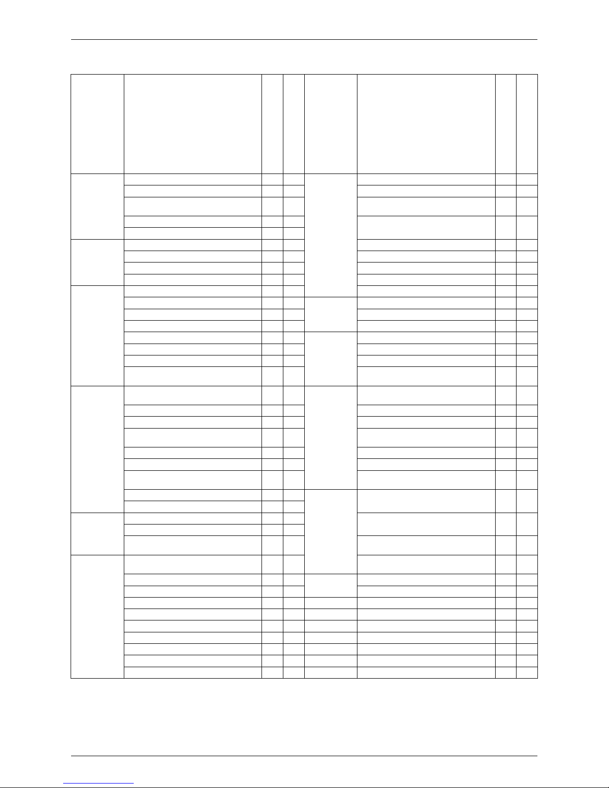
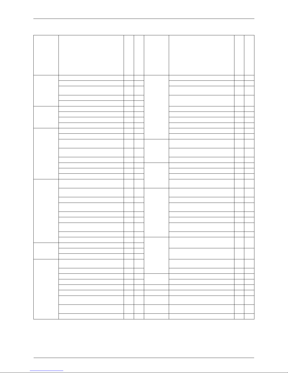
Category Functions
FTXG25/35JV1BW(S)
CTXG50JV1BW(S)
Category Functions
FTXG25/35JV1BW(S)
CTXG50JV1BW(S)
Basic
Function
Inverter (with Inverter Power Control)
{{
Health &
Clean
Air-Purifying Filter — —
Operation Limit for Cooling (°CDB)
— — Photocatalytic Deodorizing Filter — —
Operation Limit for Heating (°CWB) — —
Air-Purifying Filter with Photocatalytic
Deodorizing Function
——
PAM Control — —
Titanium Apatite Photocatalytic
Air-Purifying Filter
{{
Standby Electricity Saving — —
Compressor Oval Scroll Compressor — — Air Filter (Prefilter)
{{
Swing Compressor — — Wipe-Clean Flat Panel
{{
Rotary Compressor — — Washable Grille — —
Reluctance DC Motor — — MOLD PROOF Operation — —
Comfortable
Airflow
Power-Airflow Flap — — Good-Sleep Cooling Operation — —
Power-Airflow Dual Flaps
{{
Timer WEEKLY TIMER Operation
{{
Power-Airflow Diffuser — — 24-Hour ON/OFF TIMER
{{
Wide-Angle Louvers
{{
NIGHT SET Mode
{{
Vertical Auto-Swing (Up and Down)
{{
Worry Free
“Reliability &
Durability”
Auto-Restart (after Power Failure)
{{
Horizontal Auto-Swing (Right and Left) — — Self-Diagnosis (Digital, LED) Display
{{
3-D Airflow — — Wiring Error Check Function — —
COMFORT AIRFLOW Operation
{{
Anti-Corrosion Treatment of Outdoor
Heat Exchanger
——
Comfort
Control
Auto Fan Speed
{{
Indoor Unit Quiet Operation
{{
Flexibility
Multi-Split / Split Type Compatible
Indoor Unit
{
—
NIGHT QUIET Mode (Automatic) — —
OUTDOOR UNIT QUIET Operation
(Manual)
{{
H/P, C/O Compatible Indoor Unit — —
INTELLIGENT EYE Operation
{{
Flexible Power Supply Correspondence — —
2-Area INTELLIGENT EYE Operation — — High Ceiling Application — —
Quick Warming Function
(Preheating Operation)
— — Chargeless — —
Hot-Start Function
{{
Either Side Drain (Right or Left)
{{
Automatic Defrosting — — Power Selection — —
Operation Automatic Operation
{{
Remote
Control
5-Room Centralized Controller (Option)
{{
Program Dry Operation
{{
Fan Only
{{
Remote Control Adaptor
(Normal Open Pulse Contact) (Option)
{{
Lifestyle
Convenience
New POWERFUL Operation
(Non-Inverter)
——
Remote Control Adaptor
(Normal Open Contact) (Option)
{{
Inverter POWERFUL Operation
{{
DIII-NET Compatible (Adaptor) (Option)
{{
Priority-Room Setting — — Remote
Controller
Wireless
{{
COOL / HEAT Mode Lock — — Wired (Option)
{{
HOME LEAVE Operation — —
ECONO Operation
{{
Indoor Unit ON/OFF Button
{{
Signal Receiving Sign
{{
Multi-Colored Indicator Lamp
(Multi-Monitor Lamp)
{{
R/C with Back Light
{{
Temperature Display — —
Note:
{
: Holding Functions
— : No Functions
SiBE18-821_C Functions
List of Functions 5
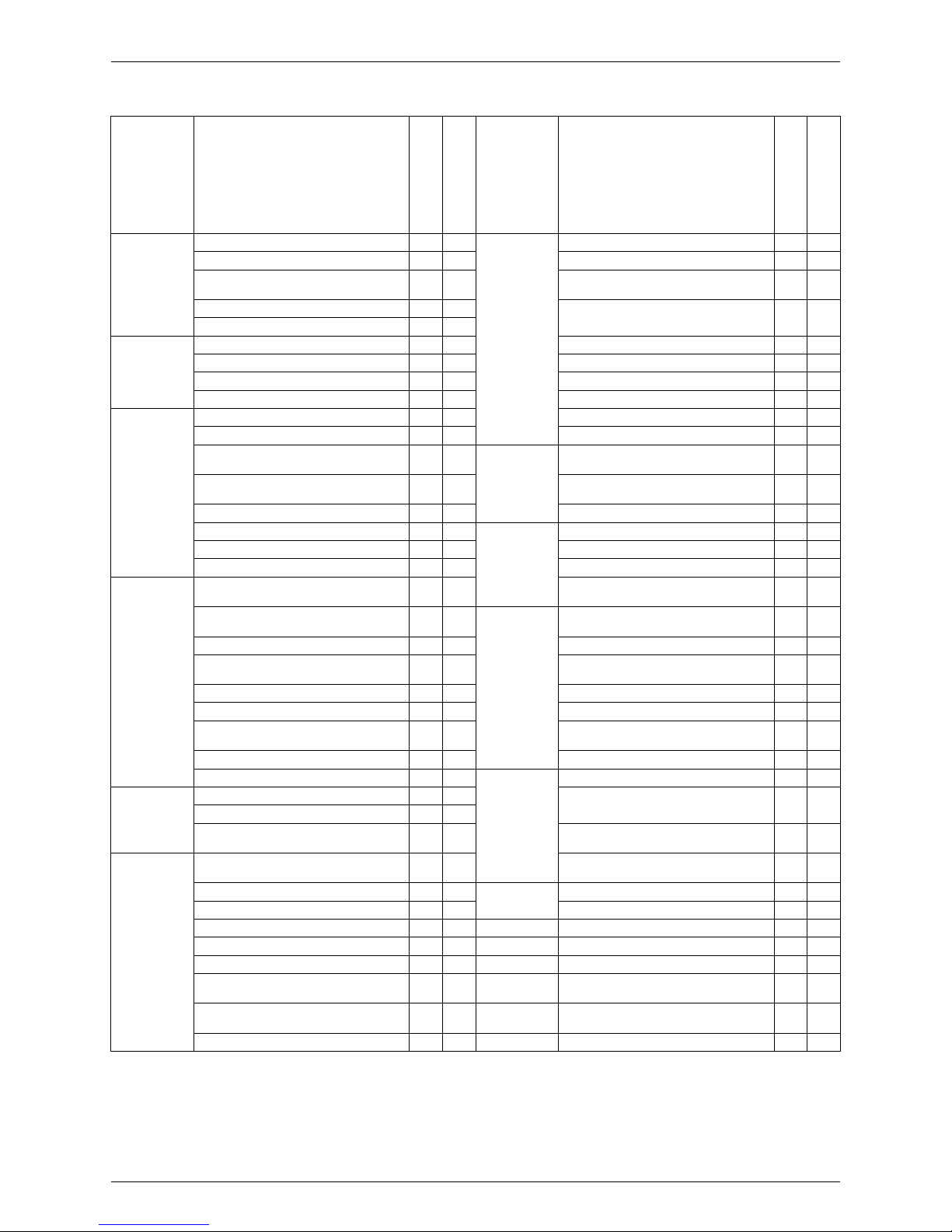
Category Functions
FTXS20/25/35/42/50G2V1B
FTXS60/71FV1B
Category Functions
FTXS20/25/35/42/50G2V1B
FTXS60/71FV1B
Basic
Function
Inverter (with Inverter Power Control)
{{
Health &
Clean
Air-Purifying Filter — —
Operation Limit for Cooling (°CDB) — — Photocatalytic Deodorizing Filter — —
Operation Limit for Heating (°CWB) — —
Air-Purifying Filter with Photocatalytic
Deodorizing Function
——
PAM Control — —
Titanium Apatite Photocatalytic
Air-Purifying Filter
{{
Standby Electricity Saving — —
Compressor Oval Scroll Compressor — — Air Filter (Prefilter)
{{
Swing Compressor — — Wipe-Clean Flat Panel
{{
Rotary Compressor — — Washable Grille — —
Reluctance DC Motor — — MOLD PROOF Operation — —
Comfortable
Airflow
Power-Airflow Flap — — Good-Sleep Cooling Operation — —
Power-Airflow Dual Flaps
{{
Timer WEEKLY TIMER Operation
{
—
Power-Airflow Diffuser — — 24-Hour ON/OFF TIMER
{{
Wide-Angle Louvers
{{
NIGHT SET Mode
{{
Vertical Auto-Swing (Up and Down)
{{
Worry Free
“Reliability &
Durability”
Auto-Restart (after Power Failure)
{{
Horizontal Auto-Swing (Right and Left)
{{
Self-Diagnosis (Digital, LED) Display
{{
3-D Airflow
{{
Wiring Error Check Function — —
COMFORT AIRFLOW Operation
{
—
Anti-Corrosion Treatment of Outdoor
Heat Exchanger
——
Comfort
Control
Auto Fan Speed
{{
Flexibility Multi-Split / Split Type Compatible
Indoor Unit
{{
Indoor Unit Quiet Operation
{{
H/P, C/O Compatible Indoor Unit
{
—
NIGHT QUIET Mode (Automatic) — — Flexible Power Supply Correspondence — —
OUTDOOR UNIT QUIET Operation
(Manual)
{{
High Ceiling Application — —
2-Area INTELLIGENT EYE Operation
{
— Chargeless — —
INTELLIGENT EYE Operation —
{
Either Side Drain (Right or Left)
{{
Quick Warming Function
(Preheating Operation)
— — Power Selection — —
Hot-Start Function
{{
Remote
Control
5-Room Centralized Controller (Option)
{{
Automatic Defrosting — —
Operation Automatic Operation
{{
Remote Control Adaptor
(Normal Open Pulse Contact) (Option)
{{
Program Dry Operation
{{
Fan Only
{{
Remote Control Adaptor
(Normal Open Contact) (Option)
{{
Lifestyle
Convenience
New POWERFUL Operation
(Non-Inverter)
— — DIII-NET Compatible (Adaptor) (Option)
{{
Inverter POWERFUL Operation
{{
Remote
Controller
Wireless
{{
Priority-Room Setting — — Wired (Option)
{{
COOL / HEAT Mode Lock — —
HOME LEAVE Operation —
{
ECONO Operation
{
—
Indoor Unit ON/OFF Button
{{
Signal Receiving Sign
{{
R/C with Back Light — —
Temperature Display — —
Note:
{
: Holding Functions
— : No Functions
Functions SiBE18-821_C
6 List of Functions
Category Functions
FTXS60/71GV1B
FVXS25/35/50FV1B
Category Functions
FTXS60/71GV1B
FVXS25/35/50FV1B
Basic
Function
Inverter (with Inverter Power Control)
{{
Health &
Clean
Air-Purifying Filter — —
Operation Limit for Cooling (°CDB) — — Photocatalytic Deodorizing Filter — —
Operation Limit for Heating (°CWB) — —
Air-Purifying Filter with Photocatalytic
Deodorizing Function
——
PAM Control — —
Titanium Apatite Photocatalytic
Air-Purifying Filter
{{
Standby Electricity Saving — —
Compressor Oval Scroll Compressor — — Air Filter (Prefilter)
{{
Swing Compressor — — Wipe-Clean Flat Panel
{{
Rotary Compressor — — Washable Grille — —
Reluctance DC Motor — — MOLD PROOF Operation — —
Comfortable
Airflow
Power-Airflow Flap — — Good-Sleep Cooling Operation — —
Power-Airflow Dual Flaps
{
— Timer WEEKLY TIMER Operation
{{
Power-Airflow Diffuser — — 24-Hour ON/OFF TIMER
{{
Wide-Angle Louvers
{{
NIGHT SET Mode
{{
Vertical Auto-Swing (Up and Down)
{{
Worry Free
“Reliability &
Durability”
Auto-Restart (after Power Failure)
{{
Horizontal Auto-Swing (Right and Left)
{
— Self-Diagnosis (Digital, LED) Display
{{
3-D Airflow
{
— Wiring Error Check Function — —
COMFORT AIRFLOW Operation
{
—
Anti-Corrosion Treatment of Outdoor
Heat Exchanger
——
Comfort
Control
Auto Fan Speed
{{
Flexibility Multi-Split / Split Type Compatible
Indoor Unit
{{
Indoor Unit Quiet Operation
{{
H/P, C/O Compatible Indoor Unit
{{
NIGHT QUIET Mode (Automatic) — — Flexible Power Supply Correspondence — —
OUTDOOR UNIT QUIET Operation
(Manual)
{{
High Ceiling Application — —
2-Area INTELLIGENT EYE Operation — — Chargeless — —
INTELLIGENT EYE Operation
{
— Either Side Drain (Right or Left)
{
—
Quick Warming Function
(Preheating Operation)
— — Power Selection — —
Hot-Start Function
{{
Remote
Control
5-Room Centralized Controller (Option)
{{
Automatic Defrosting — —
Operation Automatic Operation
{{
Remote Control Adaptor
(Normal Open Pulse Contact) (Option)
{{
Program Dry Operation
{{
Fan Only
{{
Remote Control Adaptor
(Normal Open Contact) (Option)
{{
Lifestyle
Convenience
New POWERFUL Operation
(Non-Inverter)
——
Inverter POWERFUL Operation
{{
DIII-NET Compatible (Adaptor) (Option)
{{
Priority-Room Setting — — Remote
Controller
Wireless
{{
COOL / HEAT Mode Lock — — Wired (Option)
{
—
HOME LEAVE Operation — —
ECONO Operation
{{
Indoor Unit ON/OFF Button
{{
Signal Receiving Sign
{{
R/C with Back Light —
{
Temperature Display — —
Note:
{
: Holding Functions
— : No Functions
SiBE18-821_C Functions
List of Functions 7
Category Functions
FLXS25/35/50/60BAVMB
FDXS25/35EAVMB
FDXS50/60CVMB
Category Functions
FLXS25/35/50/60BAVMB
FDXS25/35EAVMB
FDXS50/60CVMB
Basic
Function
Inverter (with Inverter Power Control)
{{
Health &
Clean
Air-Purifying Filter
{
—
Operation Limit for Cooling (°CDB) — — Photocatalytic Deodorizing Filter
{
—
Operation Limit for Heating (°CWB) — —
Air-Purifying Filter with Photocatalytic
Deodorizing Function
——
PAM Control — —
Titanium Apatite Photocatalytic
Air-Purifying Filter
——
Standby Electricity Saving — —
Compressor Oval Scroll Compressor — — Air Filter (Prefilter)
{{
Swing Compressor — — Wipe-Clean Flat Panel — —
Rotary Compressor — — Washable Grille — —
Reluctance DC Motor — — MOLD PROOF Operation — —
Comfortable
Airflow
Power-Airflow Flap — — Good-Sleep Cooling Operation — —
Power-Airflow Dual Flaps — — Timer WEEKLY TIMER Operation — —
Power-Airflow Diffuser — — 24-Hour ON/OFF TIMER
{{
Wide-Angle Louvers — — NIGHT SET Mode
{{
Vertical Auto-Swing (Up and Down)
{
— Worry Free
“Reliability &
Durability”
Auto-Restart (after Power Failure)
{{
Horizontal Auto-Swing (Right and Left) — — Self-Diagnosis (Digital, LED) Display
{{
3-D Airflow — — Wiring Error Check Function — —
COMFORT AIRFLOW Operation — —
Anti-Corrosion Treatment of Outdoor
Heat Exchanger
——
Comfort
Control
Auto Fan Speed
{{
Flexibility Multi-Split / Split Type Compatible
Indoor Unit
{{
Indoor Unit Quiet Operation
{{
H/P, C/O Compatible Indoor Unit — —
NIGHT QUIET Mode (Automatic) — — Flexible Power Supply Correspondence
{{
OUTDOOR UNIT QUIET Operation
(Manual)
{{
High Ceiling Application — —
2-Area INTELLIGENT EYE Operation — — Chargeless — —
INTELLIGENT EYE Operation — — Either Side Drain (Right or Left) — —
Quick Warming Function
(Preheating Operation)
— — Power Selection — —
Hot-Start Function
{{
Remote
Control
5-Room Centralized Controller (Option)
{{
Automatic Defrosting — —
Operation Automatic Operation
{{
Remote Control Adaptor
(Normal Open Pulse Contact) (Option)
{{
Program Dry Operation
{{
Fan Only
{{
Remote Control Adaptor
(Normal Open Contact) (Option)
{{
Lifestyle
Convenience
New POWERFUL Operation
(Non-Inverter)
——
Inverter POWERFUL Operation
{{
DIII-NET Compatible (Adaptor) (Option)
{{
Priority-Room Setting — — Remote
Controller
Wireless
{{
COOL / HEAT Mode Lock — — Wired (Option) —
{
HOME LEAVE Operation
{{
ECONO Operation — —
Indoor Unit ON/OFF Button
{{
Signal Receiving Sign
{{
R/C with Back Light — —
Temperature Display — —
Note:
{
: Holding Functions
— : No Functions
Functions SiBE18-821_C
8 List of Functions
Category Functions
FFQ25/35/50/60B8V1B
FCQ35/50/60C7VEB
Category Functions
FFQ25/35/50/60B8V1B
FCQ35/50/60C7VEB
Basic
Function
Inverter (with Inverter Power Control)
{{
Health &
Clean
Air-Purifying Filter — —
Operation Limit for Cooling (°CDB) — — Photocatalytic Deodorizing Filter — —
Operation Limit for Heating (°CWB) — —
Air-Purifying Filter with Photocatalytic
Deodorizing Function
——
PAM Control — —
Titanium Apatite Photocatalytic
Air-Purifying Filter
——
Standby Electricity Saving — —
Compressor Oval Scroll Compressor — — Longlife Filter
{{
Swing Compressor — — Wipe-Clean Flat Panel — —
Rotary Compressor — — Washable Grille
{{
Reluctance DC Motor — — Filter Cleaning Indicator
{{
Comfortable
Airflow
Power-Airflow Flap — — MOLD PROOF Operation — —
Power-Airflow Dual Flaps — — Good-Sleep Cooling Operation — —
Power-Airflow Diffuser — —
Timer
Schedule Timer Operation
{
★
2
{
★
2
Wide-Angle Louvers — — 72-Hour ON/OFF TIMER
{
★
1
{
★
1
Vertical Auto-Swing (Up and Down)
{{
NIGHT SET Mode — —
Horizontal Auto-Swing (Right and Left) — — Worry Free
“Reliability &
Durability”
Auto-Restart (after Power Failure)
{{
3-D Airflow — — Self-Diagnosis (Digital, LED) Display
{{
COMFORT AIRFLOW Operation — — Wiring Error Check Function — —
Comfort
Control
Auto Fan Speed — —
Anti-Corrosion Treatment of Outdoor
Heat Exchanger
——
Indoor Unit Quiet Operation — —
Flexibility Multi-Split / Split Type Compatible
Indoor Unit
{{
NIGHT QUIET Mode (Automatic) — — H/P, C/O Compatible Indoor Unit
{{
OUTDOOR UNIT QUIET Operation
(Manual)
— — Flexible Power Supply Correspondence — —
2-Area INTELLIGENT EYE Operation — — High Ceiling Application —
{
INTELLIGENT EYE Operation — — Chargeless — —
Quick Warming Function
(Preheating Operation)
— — Either Side Drain (Right or Left) — —
Hot-Start Function
{{
Power Selection — —
Automatic Defrosting — — Remote
Control
5-Room Centralized Controller (Option) — —
Operation Automatic Operation
{{
Program Dry Operation
{{
Remote Control Adaptor
(Normal Open Pulse Contact) (Option)
——
Fan Only
{{
Lifestyle
Convenience
New POWERFUL Operation
(Non-Inverter)
——
Remote Control Adaptor
(Normal Open Contact) (Option)
——
Inverter POWERFUL Operation — — DIII-NET Compatible (Adaptor) (Option)
{{
Priority-Room Setting — — Remote
Controller
Wireless (Option)
{{
COOL / HEAT Mode Lock — — Wired (Option)
{{
HOME LEAVE Operation — —
ECONO Operation — —
Indoor Unit ON/OFF Button
{
★
1
{
★
1
Signal Receiving Sign
{
★
1
{
★
1
Temperature Display — —
Note:
{
: Holding Functions
— : No Functions
★
1:
★
2:
with wireless remote controller
with wired remote controller
SiBE18-821_C Functions
List of Functions 9
Category Functions
FDBQ25B8V1
FBQ35/50/60C7VEB
FHQ35/50/60BVV1B
Category Functions
FDBQ25B8V1
FBQ35/50/60C7VEB
FHQ35/50/60BVV1B
Basic
Function
Inverter (with Inverter Power Control)
{{
Health &
Clean
Air-Purifying Filter — —
Operation Limit for Cooling (°CDB) — — Photocatalytic Deodorizing Filter — —
Operation Limit for Heating (°CWB) — —
Air-Purifying Filter with Photocatalytic
Deodorizing Function
——
PAM Control — —
Titanium Apatite Photo catalytic
Air-Purifying Filter
——
Standby Electricity Saving — —
Compressor Oval Scroll Compressor — — Longlife Filter
{{
Swing Compressor — — Wipe-Clean Flat Panel — —
Rotary Compressor — — Washable Grille —
{
Reluctance DC Motor — — Filter Cleaning Indicator
{{
Comfortable
Airflow
Power-Airflow Flap — — MOLD PROOF Operation — —
Power-Airflow Dual Flaps — — Good-Sleep Cooling Operation — —
Power-Airflow Diffuser — —
Timer
Schedule Timer Operation
{
{
★
2
Wide-Angle Louvers — — 72-Hour ON/OFF TIMER —
{
★
1
Vertical Auto-Swing (Up and Down) —
{
NIGHT SET Mode — —
Horizontal Auto-Swing (Right and Left) — — Worry Free
“Reliability &
Durability”
Auto-Restart (after Power Failure)
{{
3-D Airflow — — Self-Diagnosis (Digital, LED) Display
{{
COMFORT AIRFLOW Operation — — Wiring Error Check Function — —
Comfort
Control
Auto Fan Speed — —
Anti-Corrosion Treatment of Outdoor
Heat Exchanger
——
Indoor Unit Quiet Operation — —
Flexibility Multi-Split / Split Type Compatible
Indoor Unit
{{
NIGHT QUIET Mode (Automatic) — — H/P, C/O Compatible Indoor Unit
{{
OUTDOOR UNIT QUIET Operation
(Manual)
— — Flexible Power Supply Correspondence — —
2-Area INTELLIGENT EYE Operation — — High Ceiling Application —
{
INTELLIGENT EYE Operation — — Chargeless — —
Quick Warming Function
(Preheating Operation)
— — Either Side Drain (Right or Left) — —
Hot-Start Function
{{
Power Selection — —
Automatic Defrosting — — Remote
Control
5-Room Centralized Controller (Option) — —
Operation Automatic Operation
{{
Remote Control Adaptor
(Normal Open Pulse Contact) (Option)
——
Program Dry Operation
{{
Fan Only
{{
Remote Control Adaptor
(Normal Open Contact) (Option)
——
Lifestyle
Convenience
New POWERFUL Operation
(Non-Inverter)
— — DIII-NET Compatible (Adaptor) (Option)
{{
Inverter POWERFUL Operation — — Remote
Controller
Wireless (Option) —
{
Priority-Room Setting — — Wired (Option)
{{
COOL / HEAT Mode Lock — —
HOME LEAVE Operation — —
ECONO Operation — —
Indoor Unit ON/OFF Button —
{
★
1
Signal Receiving Sign —
{
★
1
Temperature Display — —
Note:
{
: Holding Functions
— : No Functions
★
1:
★
2:
with wireless remote controller
with wired remote controller

SiBE18-821_C
10 Specifications
Part 2
Specifications
1. Specifications........................................................................................11
1.1 Outdoor Unit ...........................................................................................11
1.2 BP Unit ...................................................................................................12
1.3 Indoor Unit..............................................................................................13
SiBE18-821_C Specifications
Specifications 11
1. Specifications
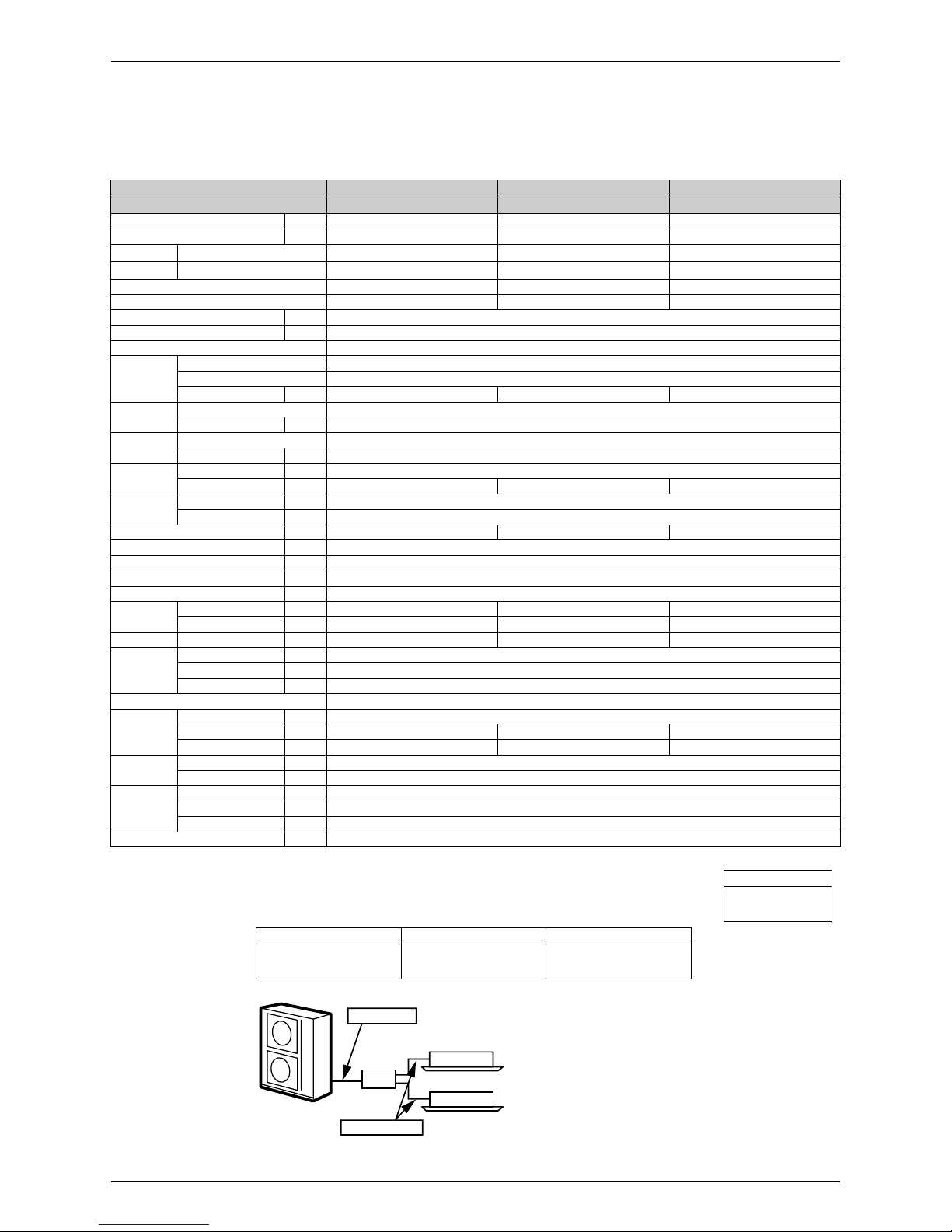
1.1 Outdoor Unit
50 Hz, 230 V
Note:
1.★ Refrigerant charge is required. (Chargeless piping length: 0 m)
Formula for calculation charge: R (kg)
R = [Total piping length (m) of
φ
9.5] × 0.054 + [Total piping length (m) of φ 6.4] × 0.022
2. The data are based on the conditions shown in the table below.
Model RMXS112E8V1B RMXS140E8V1B RMXS160E8V1B
4HP 5HP 6HP
Cooling Capacity kW 11.2 14.0 15.5
Heating Capacity kW 12.5 16.0 17.5
EER
Cooling
3.20 2.75 2.87
COP
Heating
3.18 3.07 3.22
Max. Total Indoor Unit Capacity Index 130 162.5 182
Min. Total Indoor Unit Capacity Index 50 62.5 70
Power Consumption W —
Running Current A —
Casing Color Daikin White
Compressor
Type Hermetically Sealed Scroll Type
Model JT100G-VDL
Motor Output kW 2.5 3.0 3.5
Refrigerant
Oil
Model DAPHNE FVC68D
Charge L 1.5
Refrigerant
Type R-410A
Charge kg 4.0
Airflow Rate
(H)
Cooling m³/min 106
Heating m³/min 102 105 105
Fan
Type Propeller
Motor Output W 70 + 70
Starting Current A 15.9 20.2 22.2
Dimensions (H × W × D) mm 1,345 × 900 × 320
Packaged Dimensions (H × W × D) mm 1,524 × 980 × 420
Weight (Mass) kg 125
Gross Weight (Gross Mass) kg 130
Operation
Sound
Cooling dBA 51 52 54
Heating dBA 53 54 55
Sound Power Cooling dBA 67 68 70
Piping
Connection
Liquid mm
φ
9.52 (Flare Connection)
Gas mm
φ
19.1 (Brazing Connection)
Drain mm O.D.
φ
26
No. of Wiring Connection 3 For Power Supply (Including Earth Wiring), 2 For Interunit Wiring (Outdoor Unit-BP)
Total piping
length
O.U. - BP m 55
BP - I.U. m 60 80 90
System Total m 115 135 145
Max. piping
length
BP - I.U. m 15
1st Branch - I.U. m 40
Max. level
difference
O.U. - BP m 30
O.U. - I .U. m 30
BP - BP, I.U. - I.U. m 15
Necessity of Additional Charge
★
kg/m Necessary
Cooling Heating Piping Length
Indoor: 27°CDB / 19°CWB
Outdoor: 35°CDB
Indoor: 20°CDB
Outdoor: 7°CDB / 6°CWB
Main Piping: 5 m
Branch Piping: 3 m
Level difference: 0 m
Conversion Formulae
kcal/h = kW × 860
Btu/h = kW × 3412
cfm = m³/min × 35.3
BP Unit
Outdoor Unit
Main Piping
Branch Piping
Indoor Unit
(
Q0143
)
Specifications SiBE18-821_C
12 Specifications
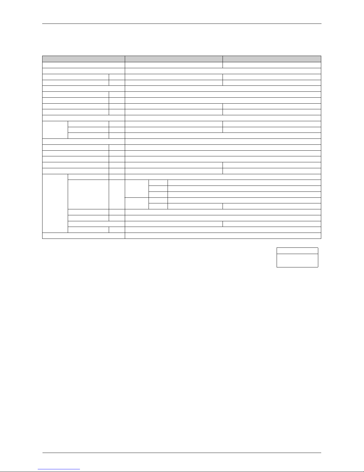
1.2 BP Unit
50 Hz, 230 V
Note:
1. BP or Indoor Unit Max. Height - BP or Indoor Unit Min. Height → Max. 15 m.
Set up BP and indoor unit within 15 m height difference.
2. The piping connection must be cut so as to suit the piping sizes of the indoor unit which will be connected.
The same sizes should be used for the pi ping on the outdoor uni t.
3. ( )* : including auxiliary piping length
Model BPMKS967B2B BPMKS967B3B
Connectable Indoor Units 1 ~ 2 Units 1 ~ 3 Units
Casing Color Paintingless
Power Consumption W 10 10
Running Current A 0.05 0.05
Refrigerant Type R-410A
Dimension (H × W × D) mm 180 × 294 (650)* × 350
Package Dimension (H × W × D) mm 257 × 738 × 427
Machine Weight (Mass) kg 7.5 8
Gross Weight (Gross Mass) kg 11 12
Number of Wiring Connections 4 for Interunit Wiring
Piping
Connection
(Brazing)
Liquid mm Main:
φ
9.5 × 1 / Branch: φ 6.4 × 2 Main: φ 9.5 × 1 / Branch: φ 6.4 × 3
Gas mm Main:
φ
19.1 × 1 / Branch: φ 15.9 × 2 Main: φ 19.1 × 1 / Branch: φ 15.9 × 3
Drain mm Drain Processingless
Heat Insulation Both Liqui d and Gas Pipes
Max. Piping Length m —
Amount of Additional Charge g/m —
Max. Height Difference m —
Max. Combination kW 14.2 20.8
Min. Combination kW 2.0 2.0
Accessories
Installation Manual pc. 1
Reducer pc.
For Main
Liquid 1 (For I.D.
φ
6.4)
Gas 1 (For I.D.
φ
12.7)
Gas 1 (For I.D.
φ
15.9, 19.1)
For Branch
Liquid 1 (For I.D. φ 9.5)
Gas 2 (For I.D.
φ
12.7, 9.5) 3 (For I.D. φ 12.7, 9.5)
Hanger Metal pc. 4
Screws pc. 8 (M4 × 8)
Heat Insulation (2pc. is 1 set) 3 Sets 4 Sets
Binding Band pc. 2
Drawing No. C: 4D050058B
Conversion Formulae
kcal/h = kW × 860
Btu/h = kW × 3412
cfm = m³/min × 35.3
SiBE18-821_C Specifications
Specifications 13
1.3 Indoor Unit
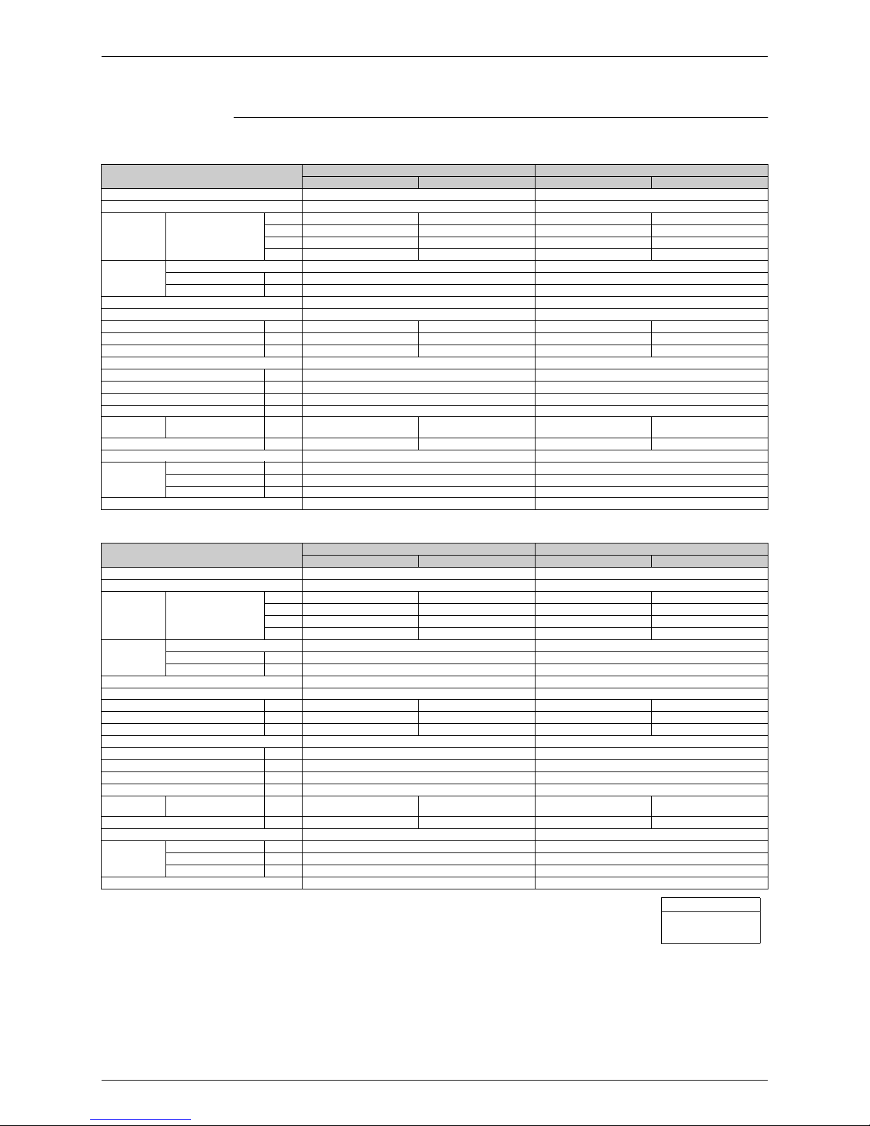
Wall Mounted Type
50 Hz, 220 - 230 - 240 V
Model
FTXG25EV1BW FTXG25EV1BS
Cooling Heating Cooling Heating
Rated Capacity 2.5 kW Class 2.5 kW Class
Front Panel Color Mat Crystal White Mat Crystal Silver
Airfl ow Rates
m³/min
(cfm)
H 7.7 (271) 9.0 (317) 7.7 (271) 9.0 (317)
M 6.1 (215) 7.9 (278) 6.1 (215) 7.9 (278)
L 4.7 (165) 6.7 (236) 4.7 (165) 6.7 (236)
SL 3.8 (134) 5.4 (190) 3.8 (134) 5.4 (190)
Fan
Type Cross Flow Fan Cross Flow Fan
Motor Output W 40 40
Speed Steps 5 Steps, Quiet, Auto 5 Steps, Quiet, Auto
Air Direction Control Right, Left, Horizontal, Downward Right, Left, Horizontal, Downward
Air Filter Removable / Washable / Mildew Proof Removable / Washable / Mildew Proof
Running Current (Rated) A 0.15 - 0.14 - 0.13 0.15 - 0.14 - 0.13 0.15 - 0. 14 - 0.13 0.15 - 0.14 - 0.13
Power Consumption (Rated) W 30 - 30 - 30 30 - 30 - 30 30 - 30 - 30 30 - 30 - 30
Power Factor (Rated) % 90.9 - 93.2 - 96.2 90.9 - 93. 2 - 96.2 90.9 - 93.2 - 96.2 90.9 - 93.2 - 96.2
Temperature Control Microcomputer Control Microcomputer Control
Dimensions (H × W × D) mm 275 × 840 × 150 275 × 840 × 150
Packaged Dimensions (H × W × D) mm 222 × 894 × 345 222 × 894 × 345
Weight (Mass) kg 9 9
Gross Weight (Gross Mass) kg 13 13
Operation
Sound
H / M / L / SL dBA 38 / 32 / 25 / 22 38 / 33 / 28 / 25 38 / 32 / 25 / 22 38 / 33 / 28 / 25
Sound Power dBA 56 56 56 56
Heat Insulation Both Liquid and Gas Pipes Both Liquid and Gas Pipes
Piping
Connection
Liquid mm
φ
6.4
φ
6.4
Gas mm
φ
9.5
φ
9.5
Drain mm
φ
18.0
φ
18.0
Drawing No. 3D051101 3D051102
Model
FTXG35EV1BW FTXG35EV1BS
Cooling Heating Cooling Heating
Rated Capacity 3.5 kW Class 3.5 kW Class
Front Panel Color Mat Crystal White Mat Crystal Silver
Airfl ow Rates
m³/min
(cfm)
H 8.1 (285) 9.6 (338) 8.1 (285) 9.6 (338)
M 6.5 (229) 8.2 (289) 6.5 (229) 8.2 (289)
L 4.9 (173) 6.7 (236) 4.9 (173) 6.7 (236)
SL 4.1 (144) 5.9 (208) 4.1 (144) 5.9 (208)
Fan
Type Cross Flow Fan Cross Flow Fan
Motor Output W 40 40
Speed Steps 5 Steps, Quiet, Auto 5 Steps, Quiet, Auto
Air Direction Control Right, Left, Horizontal, Downward Right, Left, Horizontal, Downward
Air Filter Removable / Washable / Mildew Proof Removable / Washable / Mildew Proof
Running Current (Rated) A 0.15 - 0.14 - 0.13 0.15 - 0.14 - 0.13 0.15 - 0. 14 - 0.13 0.15 - 0.14 - 0.13
Power Consumption (Rated) W 30 - 30 - 30 30 - 30 - 30 30 - 30 - 30 30 - 30 - 30
Power Factor (Rated) % 90.9 - 93.2 - 96.2 90.9 - 93. 2 - 96.2 90.9 - 93.2 - 96.2 90.9 - 93.2 - 96.2
Temperature Control Microcomputer Control Microcomputer Control
Dimensions (H × W × D) mm 275 × 840 × 150 275 × 840 × 150
Packaged Dimensions (H × W × D) mm 222 × 894 × 345 222 × 894 × 345
Weight (Mass) kg 9 9
Gross Weight (Gross Mass) kg 13 13
Operation
Sound
H / M / L / SL dBA 39 / 33 / 26 / 23 39 / 34 / 29 / 26 39 / 33 / 26 / 23 39 / 34 / 29 / 26
Sound Power dBA 57 57 57 57
Heat Insulation Both Liquid and Gas Pipes Both Liquid and Gas Pipes
Piping
Connection
Liquid mm
φ
6.4
φ
6.4
Gas mm
φ
9.5
φ
9.5
Drain mm
φ
18.0
φ
18.0
Drawing No. 3D051103 3D051104
Conversion Formulae
kcal/h = kW × 860
Btu/h = kW × 3412
cfm = m³/min × 35.3
Specifications SiBE18-821_C
14 Specifications
50 Hz, 220 - 230 - 240 V
Model
CTXG50EV1BW CTXG50EV1BS
Cooling Heating Cooling Heating
Rated Capacity 5.0 kW Class 5.0 kW Class
Front Panel Color Mat Crystal White Mat Crystal Silver
Airfl ow Rates
m³/min
(cfm)
H 11.3 (398) 12.6 (444) 11.3 (398) 12.6 (444)
M 9.1 (320) 10.6 (373) 9.1 (320) 10.6 (373)
L 7.1 (250) 8.7 (306) 7.1 (250) 8.7 (306)
SL 6.7 (236) 7.7 (271) 6.7 (236) 7.7 (271)
Fan
Type Cross Flow Fan Cross Flow Fan
Motor Output W 40 40
Speed Steps 5 Steps, Quiet, Auto 5 Steps, Quiet, Auto
Air Direction Control Right, Left, Horizontal, Downward Right, Left, Horizontal, Downward
Air Filter Removable / Washable / Mildew Proof Removable / Washable / Mildew Proof
Running Current (Rated) A 0.15 - 0.14 - 0.13 0.15 - 0.14 - 0.13 0.15 - 0. 14 - 0.13 0.15 - 0.14 - 0.13
Power Consumption (Rated) W 30 30 30 30
Power Factor (Rated) % 90.9 - 93.2 - 96.2 90.9 - 93. 2 - 96.2 90.9 - 93.2 - 96.2 90.9 - 93.2 - 96.2
Temperature Control Microcomputer Control Microcomputer Control
Dimensions (H × W × D) mm 275 × 840 × 150 275 × 840 × 150
Packaged Dimensions (H × W × D) mm 222 × 894 × 345 222 × 894 × 345
Weight (Mass) kg 9 9
Gross Weight (Gross Mass) kg 13 13
Operation
Sound
H / M / L / SL dBA 47 / 41 / 35 / 32 47 / 41 / 35 / 32 47 / 41 / 35 / 32 47 / 41 / 35 / 32
Sound Power dBA 64 64 64 64
Heat Insulation Both Liquid and Gas Pipes Both Liquid and Gas Pipes
Piping
Connection
Liquid mm
φ
6.4
φ
6.4
Gas mm
φ
12.7
φ
12.7
Drain mm
φ
18.0
φ
18.0
Drawing No. 3D051105 3D051106
Model
FTXG25JV1BW FTXG25JV1BS
Cooling Heating Cooling Heating
Rated Capacity 2.5 kW Class 2.5 kW Class
Front Panel Color White Silver
Airfl ow Rates
m³/min
(cfm)
H 8.8 (311) 9.6 (339) 8.8 (311) 9.6 (339)
M 6.8 (240) 7.9 (279) 6.8 (240) 7.9 (279)
L 4.7 (166) 6.2 (219) 4.7 (166) 6.2 (219)
SL 3.8 (134) 5.4 (191) 3.8 (134) 5.4 (191)
Fan
Type Cross Flow Fan Cross Flow Fan
Motor Output W 29 29
Speed Steps 5 Steps, Quiet, Auto 5 Steps, Quiet, Auto
Air Direction Control Right, Left, Horizontal, Downward Right, Left, Horizontal, Downward
Air Filter Removable / Washable / Mildew Proof Removable / Washable / Mildew Proof
Running Current (Rated) A 0.09 - 0.08 - 0.08 0.12 - 0.11 - 0.11 0.09 - 0. 08 - 0.08 0.12 - 0.11 - 0.11
Power Consumption (Rated) W 18 - 18 - 18 24 - 24 - 24 18 - 18 - 18 24 - 24 - 24
Power Factor (Rated) % 90.9 - 97.8 - 93.8 90.9 - 94. 9 - 90.9 90.9 - 97.8 - 93.8 90.9 - 94.9 - 90.9
Temperature Control Microcomputer Control Microcomputer Control
Dimensions (H × W × D) mm 295 × 915 × 155 295 × 915 × 155
Packaged Dimensions (H × W × D) mm 285 × 1,003 × 377 285 × 1,003 × 377
Weight (Mass) kg 11 11
Gross Weight (Gross Mass) kg 15 16
Operation
Sound
H / M / L / SL dBA 38 / 32 / 25 / 22 39 / 34 / 28 / 25 38 / 32 / 25 / 22 39 / 34 / 28 / 25
Sound Power dBA 54 55 54 55
Heat Insulation Both Liquid and Gas Pipes Both Liquid and Gas Pipes
Piping
Connection
Liquid mm
φ
6.4
φ
6.4
Gas mm
φ
9.5
φ
9.5
Drain mm
φ
16.0 or φ 18.0
φ
16.0 or φ 18.0
Drawing No. 3D066165A 3D066436A
Conversion Formulae
kcal/h = kW × 860
Btu/h = kW × 3412
cfm = m³/min × 35.3
SiBE18-821_C Specifications
Specifications 15
50 Hz, 220 - 230 - 240 V
Model
FTXG35JV1BW FTXG35JV1BS
Cooling Heating Cooling Heating
Rated Capacity 3.5 kW Class 3.5 kW Class
Front Panel Color White Silver
Airfl ow Rates
m³/min
(cfm)
H 10.1 (357) 10.8 (381) 10.1 (357) 10.8 (381)
M 7.3 (258) 8.6 (304) 7.3 (258) 8.6 (304)
L 4.6 (162) 6.4 (226) 4.6 (162) 6.4 (226)
SL 3.9 (138) 5.6 (198) 3.9 (138) 5.6 (198)
Fan
Type Cross Flow Fan Cross Flow Fan
Motor Output W 29 29
Speed Steps 5 Steps, Quiet, Auto 5 Steps, Quiet, Auto
Air Direction Control Right, Left, Horizontal, Downward Right, Left, Horizontal, Downward
Air Filter Removable / Washable / Mildew Proof Removable / Washable / Mildew Proof
Running Current (Rated) A 0.13 - 0.12 - 0.12 0.16 - 0.15 - 0.14 0.13 - 0. 12 - 0.12 0.16 - 0.15 - 0.14
Power Consumption (Rated) W 26 - 26 - 26 32 - 32 - 32 26 - 26 - 26 32 - 32 - 32
Power Factor (Rated) % 90.9 - 94.2 - 90.3 90.9 - 92. 8 - 95.2 90.9 - 94.2 - 90.3 90.9 - 92.8 - 95.2
Temperature Control Microcomputer Control Microcomputer Control
Dimensions (H × W × D) mm 295 × 915 × 155 295 × 915 × 155
Packaged Dimensions (H × W × D) mm 285 × 1,003 × 377 285 × 1,003 × 377
Weight (Mass) kg 11 11
Gross Weight (Gross Mass) kg 15 16
Operation
Sound
H / M / L / SL dBA 42 / 34 / 26 / 23 42 / 36 / 29 / 26 42 / 34 / 26 / 23 42 / 36 / 29 / 26
Sound Power dBA 58 58 58 58
Heat Insulation Both Liquid and Gas Pipes Both Liquid and Gas Pipes
Piping
Connection
Liquid mm
φ
6.4
φ
6.4
Gas mm
φ
9.5
φ
9.5
Drain mm
φ
16.0 or φ 18.0
φ
16.0 or φ 18.0
Drawing No. 3D066437A 3D066438A
Model
CTXG50JV1BW CTXG50JV1BS
Cooling Heating Cooling Heating
Rated Capacity 5.0 kW Class 5.0 kW Class
Front Panel Color White White
Airfl ow Rates
m³/min
(cfm)
H 10.5 (371) 11.4 (402) 10.5 (371) 11.4 (402)
M 8.7 (307) 9.8 (346) 8.7 (307) 9.8 (346)
L 6.9 (244) 8.1 (286) 6.9 (244) 8.1 (286)
SL 5.9 (208) 7.1 (251) 5.9 (208) 7.1 (251)
Fan
Type Cross Flow Fan Cross Flow Fan
Motor Output W 29 29
Speed Steps 5 Steps, Quiet, Auto 5 Steps, Quiet, Auto
Air Direction Control Right, Left, Horizontal, Downward Right, Left, Horizontal, Downward
Air Filter Removable / Washable / Mildew Proof Removable / Washable / Mildew Proof
Running Current (Rated) A 0.16 - 0.15 - 0.14 0.19 - 0.18 - 0.17 0.16 - 0. 15 - 0.14 0.19 - 0.18 - 0.17
Power Consumption (Rated) W 32 - 32 - 32 38 - 38 - 38 32 - 32 - 32 38 - 38 - 38
Power Factor (Rated) % 90.9 - 92.8 - 95.2 90.9 - 91. 8 - 93.1 90.9 - 92.8 - 95.2 90.9 - 91.8 - 93.1
Temperature Control Microcomputer Control Microcomputer Control
Dimensions (H × W × D) mm 295 × 915 × 155 295 × 915 × 155
Packaged Dimensions (H × W × D) mm 285 × 1,003 × 377 285 × 1,003 × 377
Weight (Mass) kg 11 11
Gross Weight (Gross Mass) kg 15 15
Operation
Sound
H / M / L / SL dBA 44 / 41 / 35 / 32 44 / 41 / 35 / 32 44 / 41 / 35 / 32 44 / 41 / 35 / 32
Sound Power dBA 60 60 60 60
Heat Insulation Both Liquid and Gas Pipes Both Liquid and Gas Pipes
Piping
Connection
Liquid mm
φ
6.4
φ
6.4
Gas mm
φ
12.7
φ
12.7
Drain mm
φ
16.0 or φ 18.0
φ
16.0 or φ 18.0
Drawing No. 3D066439B 3D066440B
Conversion Formulae
kcal/h = kW × 860
Btu/h = kW × 3412
cfm = m³/min × 35.3

Specifications SiBE18-821_C
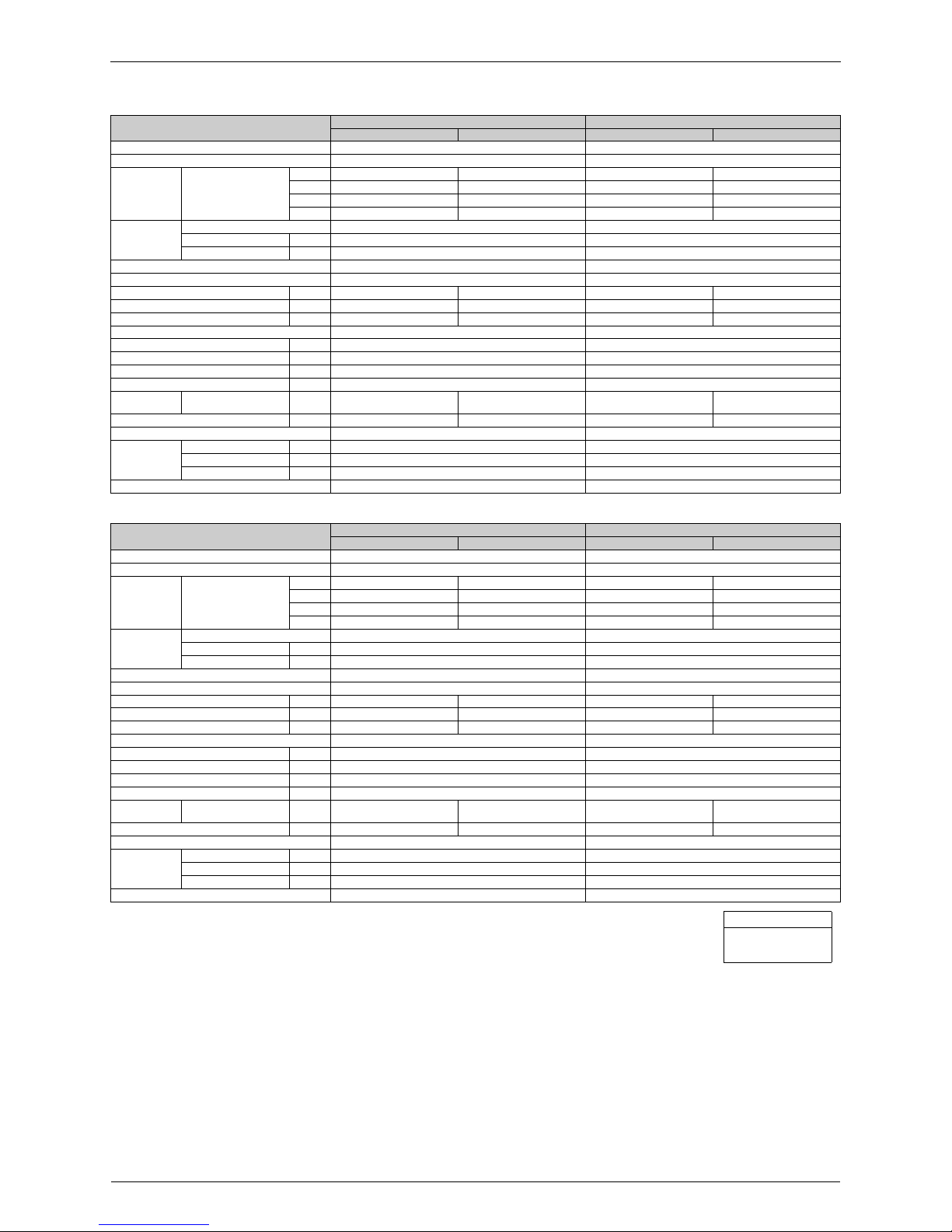
16 Specifications
50 Hz, 220 - 230 - 240 V
Model
FTXS20G2V1B FTXS25G2V1B
Cooling Heating Cooling Heating
Rated Capacity 2.0 kW Class 2.5 kW Class
Front Panel Color White White
Airfl ow Rates
m³/min
(cfm)
H 9.4 (332) 9.9 (350) 9.1 (321) 9.8 (346)
M 7.4 (262) 8.2 (290) 7.1 (252) 7.9 (280)
L 5.5 (193) 6.5 (228) 5.2 (182) 6.2 (217)
SL 4.0 (141) 5.5 (193) 3.7 (130) 5.2 (183)
Fan
Type Cross Flow Fan Cross Flow Fan
Motor Output W 23 23
Speed Steps 5 Steps, Quiet, Auto 5 Steps, Quiet, Auto
Air Direction Control Right, Left, Horizontal, Downward Right, Left, Horizontal, Downward
Air Filter Removable / Washable / Mildew Proof Removable / Washable / Mildew Proof
Running Current (Rated) A 0.09 - 0.08 - 0.08 0.10 - 0.10 - 0.09 0.09 - 0. 08 - 0.08 0.10 - 0.10 - 0.09
Power Consumption (Rated) W 18 - 18 - 18 21 - 21 - 21 18 - 18 - 18 21 - 21 - 21
Power Factor (Rated) % 90.9 - 97.8 - 93.8 95.5 - 91. 3 - 97.2 90.9 - 97.8 - 93.8 95.5 - 91.3 - 97.2
Temperature Control Microcomputer Control Microcomputer Control
Dimensions (H × W × D) mm 295 × 800 × 215 295 × 800 × 215
Packaged Dimensions (H × W × D) mm 274 × 870 × 366 274 × 870 × 366
Weight (Mass) kg 9 9
Gross Weight (Gross Mass) kg 13 13
Operation
Sound
H / M / L / SL dBA 38 / 32 / 25 / 22 38 / 33 / 28 / 25 38 / 32 / 25 / 22 39 / 34 / 28 / 25
Sound Power dBA 54 54 54 55
Heat Insulation Both Liquid and Gas Pipes Both Liquid and Gas Pipes
Piping
Connection
Liquid mm
φ
6.4
φ
6.4
Gas mm
φ
9.5
φ
9.5
Drain mm
φ
18.0
φ
18.0
Drawing No. 3D059722 3D059723
Model
FTXS35G2V1B FTXS42G2V1B
Cooling Heating Cooling Heating
Rated Capacity 3.5 kW Class 4.2 kW Class
Front Panel Color White White
Airfl ow Rates
m³/min
(cfm)
H 10.4 (367) 10.6 (374) 9.1 (321) 11.2 (395)
M 7.7 (270) 8.5 (302) 7.7 (273) 9.4 (333)
L 4.8 (170) 6.4 (226) 6.3 (221) 7.7 (271)
SL 3.5 (125) 5.4 (191) 5.4 (190) 6.8 (240)
Fan
Type Cross Flow Fan Cross Flow Fan
Motor Output W 23 23
Speed Steps 5 Steps, Quiet, Auto 5 Steps, Quiet, Auto
Air Direction Control Right, Left, Horizontal, Downward Right, Left, Horizontal, Downward
Air Filter Removable / Washable / Mildew Proof Removable / Washable / Mildew Proof
Running Current (Rated) A 0.12 - 0.12 - 0.11 0.13 - 0.13 - 0.12 0.11 - 0. 11 - 0.10 0.14 - 0.14 - 0.13
Power Consumption (Rated) W 26 - 26 - 26 28 - 28 - 28 24 - 24 - 24 30 - 30 - 30
Power Factor (Rated) % 98.5 - 94.2 - 98.5 97.9 - 93. 6 - 97.2 99.2 - 94.9 - 100.0 97.4 - 93.2 - 96.2
Temperature Control Microcomputer Control Microcomputer Control
Dimensions (H × W × D) mm 295 × 800 × 215 295 × 800 × 215
Packaged Dimensions (H × W × D) mm 274 × 870 × 366 274 × 870 × 366
Weight (Mass) kg 10 10
Gross Weight (Gross Mass) kg 13 13
Operation
Sound
H / M / L / SL dBA 42 / 34 / 26 / 23 42 / 36 / 29 / 26 42 / 38 / 33 / 30 42 / 38 / 33 / 30
Sound Power dBA 58 58 58 58
Heat Insulation Both Liquid and Gas Pipes Both Liquid and Gas Pipes
Piping
Connection
Liquid mm
φ
6.4
φ
6.4
Gas mm
φ
9.5
φ
9.5
Drain mm
φ
18.0
φ
18.0
Drawing No. 3D059724 3D059725
Conversion Formulae
kcal/h = kW × 860
Btu/h = kW × 3412
cfm = m³/min × 35.3
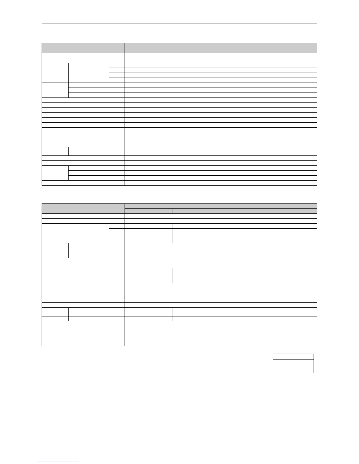
SiBE18-821_C Specifications
Specifications 17
50 Hz, 220 - 230 - 240 V
50 Hz, 230 V
Model
FTXS50G2V1B
Cooling Heating
Rated Capacity 5.0 kW Class
Front Panel Color White
Airfl ow Rates
m³/min
(cfm)
H 10.2 (360) 11.0 (388)
M 8.6 (305) 9.3 (330)
L 7.0 (246) 7.6 (267)
SL 6.0 (212) 6.7 (236)
Fan
Type Cross Flow Fan
Motor Output W 23
Speed Steps 5 Steps, Quiet, Auto
Air Direction Control Right, Left, Horizontal, Downward
Air Filter Removable / Washable / Mildew Proof
Running Current (Rated) A 0.12 - 0.12 - 0.11 0.15 - 0.14 - 0.14
Power Consumption (Rated) W 26 - 26 - 26 32 - 32 - 32
Power Factor (Rated) % 98.5 - 94.2 - 98.5 97.0 - 99.4 - 95.2
Temperature Control Microcomputer Control
Dimensions (H × W × D) mm 295 × 800 × 215
Packaged Dimensions (H × W × D) mm 274 × 870 × 366
Weight (Mass) kg 10
Gross Weight (Gross Mass) kg 13
Operation
Sound
H / M / L / SL dBA 43 / 39 / 34 / 31 44 / 39 / 34 / 31
Sound Power dBA 59 60
Heat Insulation Both Liquid and Gas Pipes
Piping
Connection
Liquid mm
φ
6.4
Gas mm
φ
12.7
Drain mm
φ
18.0
Drawing No. 3D059726
Model
FTXS60FV1B FTXS71FV1B
Cooling Heating Cooling Heating
Rated Capacity 6.0 kW Class 7.1 kW Class
Front Panel Color White White
Airfl ow Rates
m³/min
(cfm)
H 16.2 (572) 17.4 (614) 17.4 (614) 19.7 (696)
M 13.6 (480) 15.1 (533) 14.6 (516) 16.9 (597)
L 11. 4 (403) 12.7 (448) 11.6 (410) 14.3 (505)
SL 10.2 (360) 11.4 (403) 10.6 (374) 12.7 (448)
Fan
Type Cross Flow Fan Cross Flow Fan
Motor Output W 43 43
Speed Steps 5 Steps, Quiet, Auto 5 Steps, Quiet, Auto
Air Direction Control Right, Left, Horizontal, Downward Right, Left, Horizontal, Downward
Air Filter Removable / Washable / Mildew Proof Removable / Washable / Mildew Proof
Running Current (Rated) A 0.18 0.20 0.20 0.27
Power Consumption (Rated) W 40 45 45 60
Power Factor % 96.6 97.8 97.8 96.6
Temperature Control Microcomputer Control Microcomputer Control
Dimensions (H × W × D) mm 290 × 1,050 × 238 290 × 1,050 × 238
Packaged Dimensions (H × W × D) mm 337 × 1,147 × 366 337 × 1,147 × 366
Weight (Mass) kg 12 12
Gross Weight (Gross Mass) kg 17 17
Operation
Sound
H / M / L / SL dBA 45 / 41 / 36 / 33 44 / 40 / 35 / 32 46 / 42 / 37 / 34 46 / 42 / 37 / 34
Sound Power H dBA 61 60 62 62
Heat Insulation Both Liquid and Gas Pipes Both Liquid and Gas Pipes
Piping Connection
Liquid mm
φ
6.4
φ
6.4
Gas mm
φ
12.7
φ
15.9
Drain mm
φ
18.0
φ
18.0
Drawing No. 3D056020 3D056021A
Conversion Formulae
kcal/h = kW × 860
Btu/h = kW × 3412
cfm = m³/min × 35.3
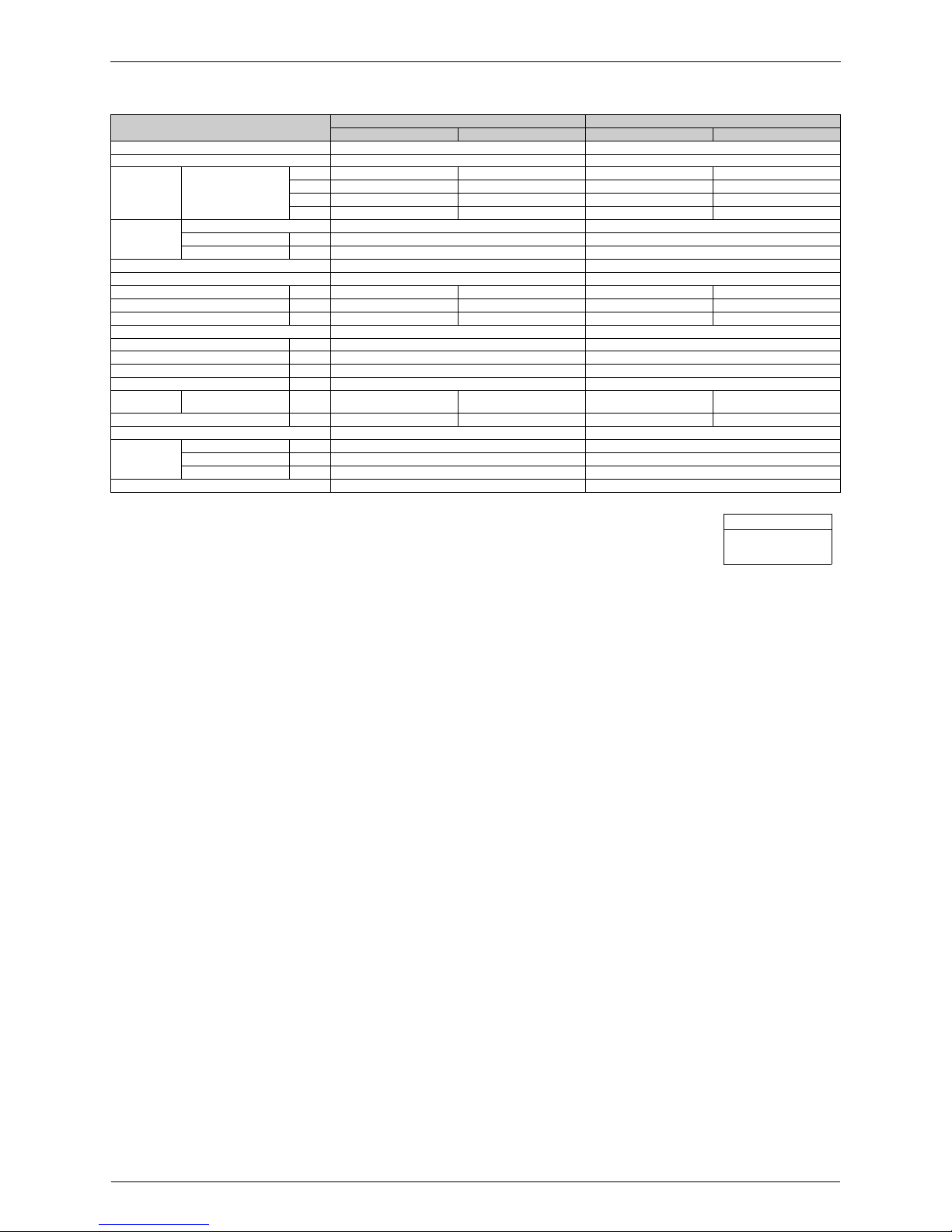
Specifications SiBE18-821_C
18 Specifications
50 Hz, 220 - 230 - 240 V
Model
FTXS60GV1B FTXS71GV1B
Cooling Heating Cooling Heating
Rated Capacity 6.0 kW Class 7.1 kW Class
Front Panel Color White White
Airfl ow Rates
m³/min
(cfm)
H 16.0 (565) 17.2 (607) 17.2 (607) 19.5 (689)
M 13.5 (477) 14.9 (526) 14.5 (512) 16.7 (590)
L 11. 3 (399) 12.6 (445) 11.5 (406) 14.2 (501)
SL 10.1 (357) 11.3 (399) 10.5 (371) 12.6 (445)
Fan
Type Cross Flow Fan Cross Flow Fan
Motor Output W 43 43
Speed Steps 5 Steps, Quiet, Auto 5 Steps, Quiet, Auto
Air Direction Control Right, Left, Horizontal, Downward Right, Left, Horizontal, Downward
Air Filter Removable / Washable / Mildew Proof Removable / Washable / Mildew Proof
Running Current (Rated) A 0.19 - 0.18 - 0.17 0.21 - 0.20 - 0.19 0.21 - 0. 20 - 0.19 0.28 - 0.27 - 0.26
Power Consumption (Rated) W 40 - 40 - 40 45 - 45 - 45 45 - 45 - 45 60 - 60 - 60
Power Factor (Rated) % 95.7 - 96.6 - 98.0 97.4 - 97. 8 - 98.7 97.4 - 97.8 - 98.7 97.4 - 96.6 - 96.2
Temperature Control Microcomputer Control Microcomputer Control
Dimensions (H × W × D) mm 290 × 1,050 × 250 290 × 1,050 × 250
Packaged Dimensions (H × W × D) mm 361 × 1,145 × 364 361 × 1,145 × 364
Weight (Mass) kg 12 12
Gross Weight (Gross Mass) kg 18 18
Operation
Sound
H / M / L / SL dBA 45 / 41 / 36 / 33 44 / 40 / 35 / 32 46 / 42 / 37 / 34 46 / 42 / 37 / 34
Sound Power dBA 61 60 62 62
Heat Insulation Both Liquid and Gas Pipes Both Liquid and Gas Pipes
Piping
Connection
Liquid mm
φ
6.4
φ
6.4
Gas mm
φ
12.7
φ
15.9
Drain mm
φ
18.0
φ
18.0
Drawing No. 3D065512A 3D065513A
Conversion Formulae
kcal/h = kW × 860
Btu/h = kW × 3412
cfm = m³/min × 35.3
 Loading...