

Page 1

INSTALLER
REFERENCE GUIDE
Daikin Altherma - Low Temperature Split
+
ERHQ011BA
ERHQ014BA
ERHQ016BA
ERLQ011CA
ERLQ014CA
ERLQ016CA
EHVH16S18CA
EHVH16S26CA
EHVX16S18CA
EHVX16S26CA
Page 2

Table of contents
Table of contents
1 About the documentation 2
1.1 About this document ........................................................................ 2
2 General safety precautions 2
2.1 About the documentation ................................................................. 2
2.1.1 Meaning of warnings and symbols ....................................... 2
2.2 For the installer ................................................................................ 3
2.2.1 General.................................................................................3
2.2.2 Installation site...................................................................... 3
2.2.3 Refrigerant............................................................................ 3
2.2.4 Water.................................................................................... 3
2.2.5 Electrical............................................................................... 4
3 About the box 4
3.1 Indoor unit........................................................................................4
3.1.1 To unpack the indoor unit .....................................................4
3.1.2 To remove the accessories from the indoor unit................... 4
4 About the units and options 5
4.1 Identification.....................................................................................5
4.1.1 Identification label: Indoor unit..............................................5
4.2 Possible combinations of units and options..................................... 5
4.2.1 List of options for indoor unit ................................................ 5
4.2.2 Possible combinations of indoor unit and outdoor unit......... 6
5 Application guidelines 6
5.1 Overview: Application guidelines ..................................................... 6
5.2 Setting up the space heating/cooling system................................... 6
5.2.1 Single room .......................................................................... 7
5.2.2 Multiple rooms – One LWT zone .......................................... 8
5.2.3 Multiple rooms – Two LWT zones ...................................... 10
5.3 Setting up an auxiliary heat source for space heating ................... 11
5.4 Setting up the domestic hot water tank .......................................... 12
5.4.1 System layout – Integrated DHW tank ............................... 12
5.4.2 System layout – Standalone DHW tank ............................. 13
5.4.3 Selecting the volume and desired temperature for the DHW
tank..................................................................................... 13
5.4.4 Setup and configuration – DHW tank ................................. 13
5.4.5 Combination: Standalone DHW tank + Solar panels..........14
5.4.6 DHW pump for instant hot water ........................................ 14
5.4.7 DHW pump for disinfection................................................. 14
5.5 Setting up the energy metering...................................................... 14
5.5.1 Produced heat....................................................................14
5.5.2 Consumed energy..............................................................15
5.5.3 Normal kWh rate power supply .......................................... 15
5.5.4 Preferential kWh rate power supply ................................... 15
5.6 Setting up the power consumption control ..................................... 16
5.6.1 Permanent power limitation ................................................ 16
5.6.2 Power limitation activated by digital inputs......................... 16
5.6.3 Power limitation process .................................................... 17
5.7 Setting up an external temperature sensor .................................... 17
6 Preparation 18
6.1 Preparing installation site ............................................................... 18
6.1.1 Installation site requirements of the indoor unit.................. 18
6.2 Preparing water piping ................................................................... 18
6.2.1 Water circuit requirements.................................................. 18
6.2.2 Formula to calculate the expansion vessel pre-pressure... 19
6.2.3 To check the water volume ................................................. 19
6.2.4 Changing the pre-pressure of the expansion vessel .......... 20
6.2.5 To check the water volume: Examples ............................... 20
6.3 Preparing electrical wiring .............................................................. 20
6.3.1 About preparing electrical wiring ........................................ 20
6.3.2 About preferential kWh rate power supply ......................... 21
6.3.3 Overview of electrical connections except
external actuators ............................................................... 21
6.3.4 Overview of electrical connections for external and internal
actuators............................................................................. 21
7 Installation 22
7.1 Opening the units........................................................................... 22
7.1.1 To open the indoor unit and switch box cover.................... 22
7.2 Mounting the indoor unit ................................................................ 23
7.2.1 To install the indoor unit ..................................................... 23
7.3 Connecting the water piping .......................................................... 23
7.3.1 To connect the water piping ...............................................23
7.3.2 To connect the pressure relief valve to the drain................ 23
7.3.3 To fill the water circuit ......................................................... 24
7.3.4 To fill the domestic hot water tank ...................................... 24
7.3.5 To insulate the water piping................................................ 24
7.4 Connecting the electrical wiring ..................................................... 24
7.4.1 About electrical compliance ............................................... 24
7.4.2 To connect the electrical wiring on the indoor unit .............25
7.4.3 To connect the main power supply..................................... 25
7.4.4 To connect the backup heater power supply...................... 26
7.4.5 To connect the user interface.............................................27
7.4.6 To connect the shut-off valve ............................................. 28
7.4.7 To connect the electrical meters.........................................29
7.4.8 To connect the domestic hot water pump...........................29
7.4.9 To connect the alarm output...............................................29
7.4.10 To connect the space cooling/heating ON/OFF output ...... 29
7.4.11 To connect the changeover to external heat source .......... 29
7.4.12 To connect the power consumption digital inputs...............29
7.5 Finishing the indoor unit installation............................................... 30
7.5.1 To fix the user interface cover to the indoor unit ................ 30
7.5.2 To close the indoor unit ...................................................... 30
8 Configuration 30
8.1 Overview: Configuration ................................................................ 30
8.1.1 To connect the PC cable to the switch box ........................ 30
8.1.2 To access the most used commands................................. 30
8.1.3 To copy the system settings from the first to the second user
interface ............................................................................. 31
8.1.4 To copy the language set from the first to the second user
interface ............................................................................. 31
8.1.5 Quick wizard: Set the system layout after first
power ON ........................................................................... 31
8.2 Basic configuration ........................................................................ 32
8.2.1 Quick wizard: Language / time and date............................32
8.2.2 Quick wizard: Standard ...................................................... 32
8.2.3 Quick wizard: Options ........................................................ 34
8.2.4 Quick wizard: Capacities (energy metering) ...................... 35
8.2.5 Space heating/cooling control ............................................ 36
8.2.6 Domestic hot water control................................................. 39
8.2.7 Contact/helpdesk number .................................................. 40
8.3 Advanced configuration/optimization ............................................. 40
8.3.1 Space heating/cooling operation: advanced ...................... 40
8.3.2 Domestic hot water control: advanced ............................... 43
8.3.3 Heat source settings .......................................................... 46
8.3.4 System settings .................................................................. 48
8.4 Menu structure: Overview .............................................................. 51
8.5 Menu structure: Overview installer settings ................................... 52
9 Commissioning 53
9.1 Overview: Commissioning ............................................................. 53
9.2 Checklist before test run ................................................................ 53
9.3 Air purge function........................................................................... 53
9.3.1 To perform a manual air purge ........................................... 53
9.3.2 To perform an automatic air purge ..................................... 54
9.3.3 To interrupt air purge .......................................................... 54
9.4 To perform a test run ...................................................................... 54
9.5 To perform an actuator test run...................................................... 54
9.5.1 Possible actuator test runs ................................................. 54
9.6 Underfloor heating screed dryout .................................................. 54
9.6.1 To program an underfloor heating screed dryout
schedule............................................................................. 55
9.6.2 To start an underfloor heating screed dryout...................... 55
9.6.3 To readout the status of an underfloor heating
screed dryout ..................................................................... 55
9.6.4 To interrupt an underfloor heating screed dryout ...............55
10 Hand-over to the user 55
Installer reference guide
1
Daikin Altherma - Low Temperature Split
4P313777-1 – 2012.05
EHVH/X16
Page 3

1 About the documentation
11 Maintenance and service 56
11.1 Overview: Maintenance.................................................................. 56
11.2 Maintenance safety precautions ....................................................56
11.2.1 Opening the indoor unit ......................................................56
11.3 Checklist for yearly maintenance for indoor unit ............................56
11.3.1 To drain the domestic hot water tank.................................. 57
12 Troubleshooting 57
12.1 Overview: Troubleshooting.............................................................57
12.2 General guidelines ......................................................................... 57
12.3 Solving problems based on symptoms .......................................... 57
12.3.1 Symptom: The unit is NOT heating or cooling as
expected .............................................................................57
12.3.2 Symptom: The compressor does NOT start (space heating
or domestic water heating) .................................................58
12.3.3 Symptom: The pump is making noise (cavitation).............. 58
12.3.4 Symptom: The pressure relief valve opens ........................58
12.3.5 Symptom: The water pressure relief valve leaks................ 58
12.3.6 Symptom: The space is NOT sufficiently heated at low
outdoor temperatures ......................................................... 58
12.3.7 Symptom: The pressure at the tapping point is temporarily
unusual high ....................................................................... 59
12.3.8 Symptom: Decoration panels are pushed away due to a
swollen tank........................................................................59
12.4 Solving problems based on error codes......................................... 59
12.4.1 Error codes: Overview........................................................59
13 Glossary 60
14 Technical data 61
14.1 Dimensions and service space ...................................................... 61
14.1.1 Dimensions and service space: Indoor unit ........................61
14.2 Components...................................................................................63
14.2.1 Components: Indoor unit ....................................................63
14.2.2 Components: Switch box (indoor unit)................................64
14.3 Functional diagrams.......................................................................65
14.3.1 Functional diagram: Indoor unit..........................................65
14.4 Piping diagram ...............................................................................66
14.4.1 Piping diagram: Indoor unit.................................................66
14.5 Wiring diagram ...............................................................................67
14.5.1 Wiring diagram – components: Indoor unit.........................67
14.6 Technical specifications.................................................................. 73
14.6.1 Technical specifications: Indoor unit ................................... 73
14.7 Operation range ............................................................................. 75
14.7.1 Operation range: Indoor unit...............................................75
14.8 ESP curve ...................................................................................... 78
14.8.1 ESP curve: Indoor unit........................................................78
14.9 Performance ...................................................................................79
14.10Combination table .......................................................................... 82
1 About the documentation
Document Contains… Format
General
safety
precautions
Indoor unit
Safety instructions that
you must read before
installing
Installation instructions
Paper (in the box of the
indoor unit)
installation
manual
Outdoor unit
installation
Installation instructions Paper (in the box of the
outdoor unit)
manual
Installer
reference
guide
Preparation of the
installation, technical
specifications, good
CD/DVD in the box of the
indoor unit)
practices, reference
data,…
Addendum
book for
optional
equipment
Additional info about how
to install optional
equipment
Paper (in the box of the
indoor unit)
CD/DVD (in the box of the
indoor unit)
Latest revisions of the supplied documentation may be available on
the regional Daikin website or via your dealer.
2 General safety precautions
2.1 About the documentation
Q The original documentation is written in English. All other
languages are translations.
Q The precautions described in this document cover very
important topics, follow them carefully.
Q All activities described in the installation manual must be
performed by an authorized installer.
2.1.1 Meaning of warnings and symbols
DANGER
Indicates a situation that results in death or serious injury.
DANGER: RISK OF ELECTROCUTION
Indicates a situation that could result in electrocution.
DANGER: RISK OF BURNING
Indicates a situation that could result in burning because of
extreme hot or cold temperatures.
1.1 About this document
Target audience
Authorized installers
Documentation set
This document is part of a documentation set. The complete set
consists of:
EHVH/X16
Daikin Altherma - Low Temperature Split
4P313777-1 – 2012.05
WARNING
Indicates a situation that could result in death or serious
injury.
CAUTION
Indicates a situation that could result in minor or moderate
injury.
NOTICE
Indicates a situation that could result in equipment or
property damage.
INFORMATION
Indicates useful tips or additional information.
Installer reference guide
2
Page 4

2 General safety precautions
2.2 For the installer
2.2.1 General
If you are not sure how to install or operate the unit, contact your
dealer.
NOTICE
Improper installation or attachment of equipment or
accessories could result in electric shock, short-circuit,
leaks, fire or other damage to the equipment. Only use
accessories, optional equipment and spare parts made or
approved by Daikin.
WARNING
Make sure installation, testing and applied materials comply
with applicable legislation (on top of the instructions
described in the Daikin documentation).
CAUTION
Wear adequate personal protective equipment (protective
gloves, safety glasses,…) when installing, maintaining or
servicing the system.
WARNING
Tear apart and throw away plastic packaging bags so that
nobody, especially children, can play with them. Possible
risk: suffocation.
DANGER: RISK OF BURNING
Q Do NOT touch the refrigerant piping, water piping or
internal parts during and immediately after operation. It
could be too hot or too cold. Give it time to return to
normal temperature. If you must touch it, wear
protective gloves.
Q Do NOT touch any accidental leaking refrigerant.
2.2.2 Installation site
Q Provide sufficient space around the unit for servicing and air
circulation.
Q Make sure the installation site withstands the unit’s weight and
vibration.
Q Make sure the area is well ventilated.
Q Make sure the unit is level.
Do NOT install the unit in the following places:
Q In potentially explosive atmospheres.
Q In places where there is machinery that emits electromagnetic
waves. Electromagnetic waves may disturb the control system,
and cause malfunction of the equipment.
Q In places where there is a risk of fire due to the leakage of
flammable gases (example: thinner or gasoline), carbon fibre,
ignitable dust.
Q In places where corrosive gas (example: sulphurous acid gas) is
produced. Corrosion of copper pipes or soldered parts may
cause the refrigerant to leak.
2.2.3 Refrigerant
NOTICE
Make sure refrigerant piping installation complies with
applicable legislation. In Europe, EN378 is the applicable
standard.
NOTICE
Make sure the field piping and connections are not
subjected to stress.
WARNING
During tests, NEVER pressurize the product with a
pressure higher than the maximum allowable pressure (as
indicated on the nameplate of the unit).
NOTICE
Provide adequate measures to prevent that the unit can be
used as a shelter by small animals. Small animals that
make contact with electrical parts can cause malfunctions,
smoke or fire.
CAUTION
Do NOT touch the air inlet or aluminum fins of the unit.
NOTICE
Q Do NOT place any objects or equipment on top of the
unit.
Q Do NOT sit, climb or stand on the unit.
In accordance with the applicable legislation, it might be necessary to
provide a logbook with the product containing at least: information on
maintenance, repair work, results of tests, stand-by periods,…
Also, at least, following information must be provided at an
accessible place at the product:
Q Instructions for shutting down the system in case of an
emergency
Q Name and address of fire department, police and hospital
Q Name, address and day and night telephone numbers for
obtaining service
In Europe, EN378 provides the necessary guidance for this logbook.
WARNING
Take sufficient precautions in case of refrigerant leakage. If
refrigerant gas leaks, ventilate the area immediately.
Possible risks:
Q Excessive refrigerant concentrations in a closed room
can lead to oxygen deficiency.
Q Toxic gas may be produced if refrigerant gas comes
into contact with fire.
WARNING
Always recover the refrigerants. Do NOT release them
directly into the environment. Use a vacuum pump to
evacuate the installation.
2.2.4 Water
NOTICE
Make sure water quality complies with EU directive
98/83 EC.
Installer reference guide
3
Daikin Altherma - Low Temperature Split
4P313777-1 – 2012.05
EHVH/X16
Page 5

3 About the box
2.2.5 Electrical
DANGER: RISK OF ELECTROCUTION
Q Turn OFF all power supply before removing the
switch box cover, connecting electrical wiring or
touching electrical parts.
Q Disconnect the power supply for more than 1 minute,
and measure the voltage at the terminals of main
circuit capacitors or electrical components before
servicing. The voltage must be less than 50 V DC
before you can touch electrical components. For the
location of the terminals, see the wiring diagram.
Q Do NOT touch electrical components with wet hands.
Q Do NOT leave the unit unattended when the service
cover is removed.
WARNING
If not factory installed, a main switch or other means for
disconnection, having a contact separation in all poles
providing full disconnection under overvoltage category III
condition, shall be installed in the fixed wiring.
WARNING
Q Only use copper wires.
Q All field wiring must be performed in accordance with
the wiring diagram supplied with the product.
Q NEVER squeeze bundled cables and make sure they
do not come in contact with the piping and sharp
edges. Make sure no external pressure is applied to
the terminal connections.
Q Make sure to install earth wiring. Do NOT earth the
unit to a utility pipe, surge absorber, or telephone
earth. Incomplete earth may cause electrical shock.
Q Make sure to use a dedicated power circuit. NEVER
use a power supply shared by another appliance.
Q Make sure to install the required fuses or circuit
breakers.
Q Make sure to install an earth leakage protector. Failure
to do so may cause electric shock or fire.
Q When installing the earth leakage protector, make sure
it is compatible with the inverter (resistant to high
frequency electric noise) to avoid unnecessary
opening of the earth leakage protector.
3 About the box
Q At delivery, the unit must be checked for damage. Any damage
must be reported immediately to the carrier’s claims agent.
Q Bring the packed unit as close as possible to its final installation
position to prevent damage during transport.
3.1 Indoor unit
3.1.1 To unpack the indoor unit
3.1.2 To remove the accessories from the indoor
unit
1 Remove the screws at the top of the unit.
2 Remove the top panel.
4x
Install power cables at least 1 meter away from televisions or radios
to prevent interference. Depending on the radio waves, a distance of
1 meter may not be sufficient.
WARNING
Q After finishing the electrical work, confirm that each
electrical component and terminal inside the electrical
components box is connected securely.
Q Make sure all covers are closed before starting up the
unit.
EHVH/X16
Daikin Altherma - Low Temperature Split
4P313777-1 – 2012.05
3 Remove the accessories.
Installer reference guide
4
Page 6

4 About the units and options
a
1x
b
1x
f
1x
a General safety precautions
b Addendum book for optional equipment
c Indoor unit installation manual
d Operation manual
e CD
f User interface kit: user interface, 4 fixing screws, 2 plugs
g Shut-off valve
h User interface cover
i Hinges for user interface cover
c
1x
g
2x
d
1x
h
1x 2x
e
1x
i
4 Reinstall the top panel.
4 About the units and options
4.1 Identification
NOTICE
When installing or servicing several units at the same time,
make sure NOT to switch the service panels between
different models.
4.1.1 Identification label: Indoor unit
Location
Model identification
Example: E HV H 04 S 18 CA 3V
Code Description
E European model
HV HV=Floor-standing indoor unit with integrated tank
H
Q H=Heating only
Q X=Heating/cooling
04 Capacity class:
Q 04=4.5 kW
Q 08=7.5 kW
Q 16=16 kW
S Integrated tank material:
S=Stainless steel
18 Integrated tank volume:
Q 18=180 l
Q 26=260 l
CA Series
3V Backup heater model
Q 3V
Q 9W
4.2 Possible combinations of units and options
4.2.1 List of options for indoor unit
User interface (EKRUCAL1, EKRUCAL2)
The user interface is delivered as an accessory with the unit. An
additional user interface is optionally available.
The additional user interface can be connected:
Q To have both:
Q control close to the indoor unit
Q room thermostat functionality in the principal space to be
heated
Q To have an interface containing other languages
The additional user interface EKRUCAL1 contains the 6 common
languages: English, German, French, Dutch, Italian, Spanish.
The additional user interface EKRUCAL2 contains other languages:
English, Swedish, Norwegian, Czech, Turkish, Portuguese.
Languages on the user interface can be uploaded by PC software or
copied from an user interface to the other.
For installation instructions, see "7.4.5 To connect the user
interface" on page 27.
Installer reference guide
5
Room thermostat (EKRTWA, EKRTR1)
You can connect an optional room thermostat to the indoor unit. This
thermostat can either be wired (EKRTWA) or wireless (EKRTR1).
For installation instructions, see the installation manual of the room
thermostat and addendum book for optional equipment.
Remote sensor for wireless thermostat (EKRTETS)
You can use a wireless indoor temperature sensor (EKRTETS) only
in combination with the wireless thermostat (EKRTR1).
For installation intructions, see the installation manual of the room
thermostat and addendum book for optional equipment.
Digital I/O PCB (EKRP1HB)
The digital I/O PCB is required to provide following signals:
Q Alarm output
Q Space heating/cooling On/OFF output
Q Changeover to external heat source
Q Only for EHVH/X16 models: Control signal for bottom plate
heater kit EKBPHTH16A
For installation instructions, see the installation manual of the digital
I/O PCB and addendum book for optional equipment.
Daikin Altherma - Low Temperature Split
4P313777-1 – 2012.05
EHVH/X16
Page 7

5 Application guidelines
Demand PCB (EKRP1AHTA)
To enable the power saving consumption control by digital inputs you
must install the demand PCB.
For installation instructions, see the installation manual of the
demand PCB and addendum book for optional equipment.
Remote indoor sensor (KRCS01-1)
By default the internal user interface sensor will be used as room
temperature sensor.
As an option the remote indoor sensor can be installed to measure
the room temperature on another location.
For installation instructions, see the installation manual of the remote
indoor sensor and addendum book for optional equipment.
INFORMATION
Q The remote indoor sensor can only be used in case
the user interface is configured with room thermostat
functionality.
Q You can only connect either the remote indoor sensor
or the remote outdoor sensor.
Remote outdoor sensor (EKRSCA1)
By default the sensor inside the outdoor unit will be used to measure
the outdoor temperature.
As an option the remote outdoor sensor can be installed to measure
the outdoor temperature on another location (e.g. to avoid direct
sunlight) to have an improved system behaviour.
For installation instructions, see the installation manual of the remote
outdoor sensor.
INFORMATION
You can only connect either the remote indoor sensor or
the remote outdoor sensor.
PC configurator (EKPCCAB1)
The PC cable makes a connection between the switch box of the
indoor unit and a PC. It gives the possibility to upload different
language files to the user interface and indoor parameters to the
indoor unit. For the available language files, contact your local dealer.
The software and corresponding operating instructions are available
on Daikin Extranet.
For installation instructions, see the installation manual of the PC
cable.
4.2.2 Possible combinations of indoor unit and outdoor unit
Indoor unit
Outdoor unit
ERHQ011BAV3 O O O O
ERHQ014BAV3 O O O O
ERHQ016BAV3 O O O O
ERLQ011CAV3 O O O O
ERLQ014CAV3 O O O O
ERLQ016CAV3 O O O O
ERHQ011BAW1 O O O O
ERHQ014BAW1 O O O O
ERHQ016BAW1 O O O O
ERLQ011CAW1 O O O O
ERLQ014CAW1 O O O O
ERLQ016CAW1 O O O O
EHVH16S18CA3V EHVX16S18CA3V EHVH16S26CA9W EHVX16S26CA9W
5 Application guidelines
5.1 Overview: Application guidelines
The purpose of the application guidelines is to give a glance of the
possibilities of the Daikin heat pump system.
NOTICE
Q The illustrations in the application guidelines are
meant for reference only, and are NOT to be used as
detailed hydraulic diagrams. The detailed hydraulic
dimensioning and balancing are NOT shown, and are
the responsibility of the installer.
Q For more information about the configuration settings
to optimize heat pump operation, see the configuration
chapter.
This chapter contains applications guidelines for:
Q Setting up the space heating/cooling system
Q Setting up an auxiliary heat source for space heating
Q Setting up the domestic hot water tank
Q Setting up the energy metering
Q Setting up the power consumption
Q Setting up an external temperature sensor
EHVH/X16
Daikin Altherma - Low Temperature Split
4P313777-1 – 2012.05
5.2 Setting up the space heating/cooling system
The Daikin heat pump system supplies leaving water to heat emitters
in one or more rooms.
Because the system offers a wide flexibility to control the temperature
in each room, you need to answer the following questions first:
Q How many rooms are heated (or cooled) by the Daikin
heat pump system?
Q Which heat emitter types are used in each room and what is
their design leaving water temperature?
Once the space heating/cooling requirements are clear, Daikin
recommends to follow the setup guidelines below.
Installer reference guide
6
Page 8

5 Application guidelines
B
A
a
B
A
b
a
5.2.1 Single room
Under floor heating or radiators – Wired room
thermostat
Setup
A Main leaving water temperature zone
B One single room
Q The under floor heating or radiators are directly connected to the
indoor unit.
Q The room temperature is controlled by the user interface, which
is used as room thermostat. Possible installations:
Q User interface (standard equipment) installed in the room
Q User interface (standard equipment) installed at the indoor
Configuration
Unit temperature control:
Q #: [A.2.1.7]
Q Code: [C-07]
Number of water temperature
zones:
Q #: [A.2.1.8]
Q Code: [7-02]
Benefits
Q Cost effective. You do NOT need an additional external room
thermostat.
Q Highest comfort and efficiency. The smart room thermostat
functionality can decrease or increase the desired leaving water
temperature based on the actual room temperature
(modulation). This results in:
Q Stable room temperature matching the desired temperature
Q Less ON/OFF cycles (more quiet, higher comfort and
Q Lowest possible leaving water temperature (higher
Q Easy. You can easily set the desired room temperature via the
user interface:
Q For your daily needs, you can use preset values and
Q To deviate from your daily needs, you can temporarily
a User interface used as room thermostat
and used as room thermostat
unit and used for control close to the indoor unit + user
interface (optional equipment EKRUCAL) installed in the
room and used as room thermostat
Setting Val ue
2 (RT control): Unit operation is
decided based on the ambient
temperature of the user interface.
0 (1 LWT zone): Main
(higher comfort)
higher efficiency)
efficiency)
schedules.
overrule the preset values and schedules, use the holiday
mode…
Under floor heating or radiators – Wireless room
thermostat
Setup
A Main leaving water temperature zone
B One single room
a Receiver for wireless external room thermostat
Q The under floor heating or radiators are directly connected to the
indoor unit.
Q The room temperature is controlled by the wireless external
room thermostat (optional equipment EKRTR1).
Configuration
Unit temperature control:
Q #: [A.2.1.7]
Q Code: [C-07]
Number of water temperature
zones:
Q #: [A.2.1.8]
Q Code: [7-02]
External room thermostat for the
main zone:
Q #: [A.2.2.4]
Q Code: [C-05]
Benefits
Q Wireless. The Daikin external room thermostat is available in a
wireless version.
Q Efficiency. Although the external room thermostat only sends
ON/OFF signals, it is specifically designed for the heat pump
system.
Q Comfort. In case of under floor heating, the wireless external
room thermostat prevents condensation on the floor during
cooling operation by measuring the room humidity.
b Wireless external room thermostat
Setting Valu e
1 (Ext RT control): Unit operation
is decided by the external
thermostat.
0 (1 LWT zone): Main
Configure according to the setup:
Q 1 (Thermo ON/OFF): When
the used external room
thermostat or heat pump
convector can only send a
thermo ON/OFF condition.
No separation between
heating or cooling demand.
Q 2 (C/H request): When the
used external room
thermostat can send a
separate heating/cooling
thermo ON/OFF condition.
Installer reference guide
7
Daikin Altherma - Low Temperature Split
4P313777-1 – 2012.05
EHVH/X16
Page 9

5 Application guidelines
B
A
a
B
A
a
M1
Heat pump convectors
Setup
A Main leaving water temperature zone
B One single room
Q The heat pump convectors are directly connected to the indoor
a Remote controller of the heat pump convectors
unit.
Q The desired room temperature is set via the remote controller of
the heat pump convectors.
Q The space heating/cooling demand signal is sent to one digital
input on the indoor unit (X2M/1 and X2M/4).
Q The space operation mode is sent to the heat pump convectors
by one digital output on the indoor unit (X2M/33 and X2M/34).
INFORMATION
When using multiple heat pump convectors, make sure
each one receives the infrared signal from the remote
controller of the heat pump convectors.
Configuration
Setting Val ue
Unit temperature control:
Q #: [A.2.1.7]
Q Code: [C-07]
Number of water temperature
1 (Ext RT control): Unit operation
is decided by the external
thermostat.
0 (1 LWT zone): Main
zones:
Q #: [A.2.1.8]
Q Code: [7-02]
External room thermostat for the
main zone:
Q #: [A.2.2.4]
Q Code: [C-05]
1 (Thermo ON/OFF): When the
used external room thermostat or
heat pump convector can only
send a thermo ON/OFF
condition. No separation
between heating or cooling
demand.
Benefits
Q Cooling. The heat pump convector offers, besides heating
capacity, also excellent cooling capacity.
Q Efficiency. Optimal energy efficiency because of the interlink
function.
Q Stylish.
Combination: Under floor heating + Heat pump
convectors
Q Space heating is provided by:
Q The under floor heating
Q The heat pump convectors
Q Space cooling is provided by the heat pump convectors only.
The under floor heating is shut off by the shut-off valve.
Setup
A Main leaving water temperature zone
B One single room
Q The heat pump convectors are directly connected to the indoor
a Remote controller of the heat pump convectors
unit.
Q A shut-off valve (field supply) is installed before the under floor
heating to prevent condensation on the floor during cooling
operation.
Q The desired room temperature is set via the remote controller of
the heat pump convectors.
Q The space heating/cooling demand signal is sent to one digital
input on the indoor unit (X2M/1 and X2M/4)
Q The space operation mode is sent by one digital output (X2M/33
and X2M/34) on the indoor unit to:
Q The heat pump convectors
Q The shut-off valve
Configuration
Setting Value
Unit temperature control:
Q #: [A.2.1.7]
Q Code: [C-07]
Number of water temperature
1 (Ext RT control): Unit operation
is decided by the external
thermostat.
0 (1 LWT zone): Main
zones:
Q #: [A.2.1.8]
Q Code: [7-02]
External room thermostat for the
main zone:
Q #: [A.2.2.4]
Q Code: [C-05]
1 (Thermo ON/OFF): When the
used external room thermostat or
heat pump convector can only
send a thermo ON/OFF
condition. No separation
between heating or cooling
demand.
Benefits
Q Cooling. Heat pump convectors provide, besides heating
capacity, also excellent cooling capacity.
Q Efficiency. Under floor heating has the best performance with
Altherma LT.
Q Comfort. The combination of the two heat emitter types
provides:
Q The excellent heating comfort of the under floor heating
Q The excellent cooling comfort of the heat pump convectors
5.2.2 Multiple rooms – One LWT zone
If only one leaving water temperature zone is needed because the
design leaving water temperature of all heat emitters is the same, you
do NOT need a mixing valve station (cost effective).
Example: If the heat pump system is used to heat up one floor where
all the rooms have the same heat emitters.
EHVH/X16
Daikin Altherma - Low Temperature Split
4P313777-1 – 2012.05
Installer reference guide
8
Page 10

5 Application guidelines
T
BC
A
a
M2M1
BC
A
aa
b
B
A
aa
C
Under floor heating or radiators – Thermostatic
valves
If you are heating up rooms with under floor heating or radiators, a
very common way is to control the temperature of the main room by
using a thermostat (this can either be the user interface or an
external room thermostat), while the other rooms are controlled by
so-called thermostatic valves, which open or close depending on the
room temperature.
Setup
A Main leaving water temperature zone
B Room 1
C Room 2
Q The under floor heating of the main room is directly connected to
the indoor unit.
Q The room temperature of the main room is controlled by the user
interface used as thermostat.
Q A thermostatic valve is installed before the under floor heating in
each of the other rooms.
Configuration
Unit temperature control:
Q #: [A.2.1.7]
Q Code: [C-07]
Number of water temperature
zones:
Q #: [A.2.1.8]
Q Code: [7-02]
Benefits
Q Cost effective.
Q Easy. Same installation as for one room, but with thermostatic
valves.
a User interface
NOTICE
Mind situations where the main room can be heated by
another heating source. Example: Fireplaces.
Setting Val ue
2 (RT control): Unit operation is
decided based on the ambient
temperature of the user interface.
0 (1 LWT zone): Main
Under floor heating or radiators – Multiple external
room thermostats
Setup
A Main leaving water temperature zone
B Room 1
C Room 2
a External room thermostat
Q For each room, a shut-off valve (field supplied) is installed to
b Bypass valve
avoid leaving water supply when there is no heating or cooling
demand.
Q A bypass valve must be installed to make water recirculation
possible when all shut-off valves are closed.
Q The user interface connected to the indoor unit decides the
space operation mode. Mind that the operation mode on each
room thermostat must be set to match the indoor unit.
Q The room thermostats are connected to the shut-off valves, but
do NOT have to be connected to the indoor unit. The indoor unit
will supply leaving water all the time, with the possibility to
program a leaving water schedule.
Configuration
Setting Valu e
Unit temperature control:
Q #: [A.2.1.7]
Q Code: [C-07]
Number of water temperature
0 (LWT control): Unit operation is
decided based on the leaving
water temperature.
0 (1 LWT zone): Main
zones:
Q #: [A.2.1.8]
Q Code: [7-02]
Benefits
Compared with under floor heating or radiators for one room:
Q Comfort. You can set the desired room temperature, including
schedules, for each room via the room thermostats.
Heat pump convectors
Setup
Installer reference guide
9
A Main leaving water temperature zone
B Room 1
B Room 2
Q The desired room temperature is set via the remote controller of
a Remote controller of the heat pump convectors
the heat pump convectors.
Daikin Altherma - Low Temperature Split
4P313777-1 – 2012.05
EHVH/X16
Page 11

5 Application guidelines
B
A
aa
C
E
D
b
c
Q The user interface connected to the indoor unit decides the
space operation mode.
Q The heating or cooling demand signals of each heat pump
convector are connected in parallel to the digital input on the
indoor unit (X2M/1 and X2M/4). The indoor unit will only supply
leaving water temperature when there is an actual demand.
NOTICE
To increase comfort and performance, Daikin recommends
to install the valve kit option EKVKHPC on each heat pump
convector.
Configuration
Setting Val ue
Unit temperature control:
Q #: [A.2.1.7]
Q Code: [C-07]
Number of water temperature
1 (Ext RT control): Unit operation
is decided by the external
thermostat.
0 (1 LWT zone): Main
zones:
Q #: [A.2.1.8]
Q Code: [7-02]
Benefits
Compared with heat pump convectors for one room:
Q Comfort. You can set the desired room temperature, including
schedules, for each room via the remote controller of the
heat pump convectors.
Combination: Under floor heating + Heat pump
convectors
Setup
NOTICE
To increase comfort and performance, Daikin recommends
to install the valve kit option EKVKHPC on each heat pump
convector.
Configuration
Setting Value
Unit temperature control:
Q #: [A.2.1.7]
Q Code: [C-07]
Number of water temperature
0 (LWT control): Unit operation is
decided based on the leaving
water temperature.
0 (1 LWT zone): Main
zones:
Q #: [A.2.1.8]
Q Code: [7-02]
5.2.3 Multiple rooms – Two LWT zones
If the heat emitters selected for each room are designed for different
leaving water temperatures, you can use different leaving water
temperature zones (maximum 2).
In this document:
Q Main zone = Zone with the lowest design temperature in
heating, and the highest design temperature in cooling
Q Additional zone = The other zone
CAUTION
When there is more than one leaving water zone, you must
always install a mixing valve station in the main zone to
decrease (in heating)/increase (in cooling) the leaving
water temperature when the additional zone has demand.
Typical example:
A
BC
M1
M1
b
a
A Main leaving water temperature zone
B Room 1
C Room 2
a External room thermostat
Q For each room with heat pump convectors: The heat pump
b Remote controller of the heat pump convectors
convectors are directly connected to the indoor unit.
Q For each room with under floor heating: Two shut-off valves
(field supply) are installed before the under floor heating:
Q A shut-off valve to prevent hot water supply when the room
has no heating demand
Q A shut-off valve to prevent condensation on the floor during
cooling operation of the rooms with heat pump convectors
Q For each room with heat pump convectors: The desired room
temperature is set via the remote controller of the heat pump
convectors.
Q For each room with under floor heating: The desired room
temperature is set via the external room thermostat (wired or
wireless).
Q The user interface connected to the indoor unit decides the
space operation mode. Mind that the operation mode on each
external room thermostat and remote controller of the
heat pump convectors must be set to match the indoor unit.
Heat emitters: Design
Room (zone)
temperature
Living room (main zone) Under floor heating:
Q In heating: 35°C
Q In cooling: 20°C (only
refreshment, no real cooling
allowed)
Bed rooms (additional zone) Heat pump convectors:
Q In heating: 45°C
Q In cooling: 12°C
Setup
EHVH/X16
Daikin Altherma - Low Temperature Split
4P313777-1 – 2012.05
Installer reference guide
10
Page 12

5 Application guidelines
abcdefgh j
FHL1
FHL2
FHL3
M
h
i
il
k
f
m
n
A Additional leaving water temperature zone
B Room 1
C Room 2
D Main leaving water temperature zone
E Room 3
a Remote controller of the heat pump convectors
b User interface
Q For the main zone:
Q A mixing valve station is installed before the under floor
c Mixing valve station
heating.
Q The pump of the mixing valve station is controlled by the
ON/OFF signal on the indoor unit (X2M/5 and X2M/7;
normal closed shut-off valve output).
Q The room temperature is controlled by the user interface,
which is used as room thermostat.
Q For the additional zone:
Q The heat pump convectors are directly connected to the
indoor unit.
Q The desired room temperature is set via the remote
controller of the heat pump convectors for each room.
Q The heating or cooling demand signals of each heat pump
convector are connected in parallel to the digital input on
the indoor unit (X2M/1 and X2M/4). The indoor unit will only
supply the desired additional leaving water temperature
when there is an actual demand.
Q The user interface connected to the indoor unit decides the
space operation mode. Mind that the operation mode on each
remote controller of the heat pump convectors must be set to
match the indoor unit.
Configuration
Setting Val ue
Unit temperature control:
Q #: [A.2.1.7]
Q Code: [C-07]
2 (RT control): Unit operation is
decided based on the ambient
temperature of the user interface.
Note:
Q Main room = user interface
used as room thermostat
functionality
Q Other rooms = external
room thermostat
functionality
Number of water temperature
zones:
Q #: [A.2.1.8]
Q Code: [7-02]
In case of heat pump convectors:
External room thermostat for the
additional zone:
Q #: [A.2.2.5]
Q Code: [C-06]
1 (2 LWT zones): Main +
additional
1 (Thermo ON/OFF): When the
used external room thermostat or
heat pump convector can only
send a thermo ON/OFF
condition. No separation
between heating or cooling
demand.
Shut-off valve output Set to follow the thermo demand
of the main zone.
Shut-off valve If the main zone must be shut off
during cooling mode to prevent
condensation on the floor, set it
accordingly.
At the mixing valve station Set the desired main leaving
water temperature for heating
and/or cooling.
Benefits
Q Comfort.
Q The smart room thermostat functionality can decrease or
increase the desired leaving water temperature based on
the actual room temperature (modulation).
Q The combination of the two heat emitter systems provides
the excellent heating comfort of the under floor heating, and
the excellent cooling comfort of the heat pump convectors.
Q Efficiency.
Q Depending on the demand, the indoor unit supplies
different leaving water temperature matching the design
temperature of the different heat emitters.
Q Under floor heating has the best performance with
Altherma LT.
5.3 Setting up an auxiliary heat source for space
heating
Q Space heating can be done by:
Q The indoor unit
Q An auxiliary boiler (field supply) connected to the system
Q When the room thermostat requests heating, the indoor unit or
the auxiliary boiler starts operating depending on the outdoor
temperature (status of the changeover to external heat source).
When the permission is given to the auxiliary boiler, the space
heating by the indoor unit is turned OFF.
Q Bivalent operation is only possible for space heating, NOT for
domestic hot water production. Domestic hot water is always
produced by the DHW tank connected to the indoor unit.
INFORMATION
Q During heating operation of the heat pump, the
heat pump operates to achieve the desired
temperature set via the user interface. When weatherdependent operation is active, the water temperature
is determined automatically depending on the outdoor
temperature.
Q During heating operation of the auxiliary boiler, the
auxiliary boiler operates to achieve the desired water
temperature set via the auxiliary boiler controller.
Setup
Q Integrate the auxiliary boiler as follows:
Installer reference guide
11
Daikin Altherma - Low Temperature Split
4P313777-1 – 2012.05
EHVH/X16
Page 13

5 Application guidelines
a Outdoor unit
b Indoor unit
c Heat exchanger
d Backup heater
e Pump
f Shut-off valve
g Motorised 3-way valve (delivered with DHW tank)(field
supply)
h Non-return valve
i Shut-off valve
j Collector (field supply)
k Auxiliary boiler (field supply)
l Aquastat valve (field supply)
m DHW tank (option)
n Heat exchanger coil
FHL1...3 Under floor heating
NOTICE
Q Make sure the auxiliary boiler and its integration in the
system complies with applicable legislation.
Q Daikin is NOT responsible for incorrect or unsafe
situations in the auxiliary boiler system.
Q Make sure the return water to the heat pump does NOT exceed
55°C. To do so:
Q Set the desired water temperature via the auxiliary boiler
controller to maximum 55°C.
Q Install an aquastat valve in the return water flow of the
heat pump.
Q Set the aquastat valve to close above 55°C and to open
below 55°C.
Q Install non-return valves.
Q Make sure to only have one expansion vessel in the water
circuit. An expansion vessel is already is already premounted in
the indoor unit.
Q Install the digital I/O PCB (option EKRP1HB).
Q Connect X1 and X2 (changeover to external heat source) on the
PCB to the auxiliary boiler thermostat.
Q To setup the heat emitters, see setting up the space
heating/cooling application guidelines).
Q Setup: Connect the following field wiring:
L
H
Com
Indoor/Auto/Boiler
A
K2AK1A
Indoor
X2M
1234 XY
K2AK1A
N
BTIBoiler thermostat input
A Auxiliary contact (normal closed)
H Heating demand room thermostat (optional)
K1A Auxiliary relay for activation of indoor unit (field supply)
K2A Auxiliary relay for activation of boiler (field supply)
Indoor Indoor unit
Auto Automatic
Boiler Boiler
NOTICE
Q Make sure the auxiliary contact has enough differential
or time delay to prevent frequent changeover between
indoor unit and auxiliary boiler.
Q If the auxiliary contact is an outdoor temperature
thermostat, install the thermostat in the shadow so that
it is NOT influenced or turned ON/OFF by direct
sunlight.
Q Frequent changeover may cause corrosion of the
auxiliary boiler. Contact the manufacturer of the
auxiliary boiler for more information.
5.4 Setting up the domestic hot water tank
The DHW tank can be:
Q Integrated in the indoor unit
Q Installed standalone as option
5.4.1 System layout – Integrated DHW tank
B
TI
Configuration
Via the user interface (quick wizard):
Q Set the use of a bivalent system as external heat source.
Q Set the bivalent temperature and hysteresis.
NOTICE
Q Make sure the bivalent hysteresis has enough
differential to prevent frequent changeover between
indoor unit and auxiliary boiler.
Q Because the outdoor temperature is measured by the
outdoor unit air thermistor, install the outdoor unit in
the shadow so that it is NOT influenced or turned
ON/OFF by direct sunlight.
Q Frequent changeover may cause corrosion of the
auxiliary boiler. Contact the manufacturer of the
auxiliary boiler for more information.
Changeover to external heat source decided by an auxiliary
contact
Q Only possible in external room thermostat control AND one
leaving water temperature zone (see setting up space
heating/cooling application guideline).
Q The auxiliary contact can be:
Q An outdoor temperature thermostat
Q An electricity tariff contact
Q A manually operated contact
Q …
abcd hh if
M
e
a Outdoor unit
b Indoor unit
c Heat exchanger
d Backup heater
e Pump
f Motorised 3-way valve
g DHW tank
h Shut-off valve
i Collector (field supply)
FHL1...3 Under floor heating
UI User interface
UI
FHL1
FHL2
FHL3
g
EHVH/X16
Daikin Altherma - Low Temperature Split
4P313777-1 – 2012.05
Installer reference guide
12
Page 14

5 Application guidelines
5.4.2 System layout – Standalone DHW tank
abcde hfg
M
f
a Outdoor unit
b Indoor unit
c Heat exchanger
d Backup heater
e Pump
f Shut-off valve
g Motorised 3-way valve
h Collector (field supply)
i DHW tank
j Heat exchanger coil
FHL1...3 Under floor heating
FHL1
ij
FHL2
FHL3
5.4.3 Selecting the volume and desired
temperature for the DHW tank
People experience water as hot when its temperature is 40°C.
Therefore, the DHW consumption is always expressed as equivalent
hot water volume at 40°C. However, you can set the DHW tank
temperature at a higher temperature (example: 53°C), which is then
mixed with cold water (example: 15°C).
Selecting the volume and desired temperature for the DHW tank
consists of:
1 Determining the DHW consumption (equivalent hot water
volume at 40°C).
2 Determining the volume and desired temperature for the DHW
tank.
Possible DHW tank volumes
Typ e Possible volumes
Integrated DHW tank
Standalone DHW tank
Energy saving tips
Q If the DHW consumption differs from day to day, you can
program a weekly schedule with different desired DHW tank
temperatures for each day.
Q The lower the desired DHW tank temperature, the more cost
effective. By selecting a larger DHW tank, you can lower the
desired DHW tank temperature.
Q The heat pump itself can produce domestic hot water of
maximum 55°C (50°C if outdoor temperature is low). The
electrical resistance integrated in the heat pump can higher this
temperature. However, this consumes more energy. Daikin
recommends to set the desired DHW tank temperature below
55°C to avoid using the electrical resistance.
Q The higher the outdoor temperature, the better the performance
of the heat pump.
Q 180 l
Q 260 l
Q 150 l
Q 200 l
Q 300 l
Q If energy prices are the same during the day and the night,
Daikin recommends to heat up the DHW tank during the
day.
Q If energy prices are lower during the night, Daikin
recommends to heat up the DHW tank during the night.
Q When the heat pump produces domestic hot water, it cannot
heat up a space. When you need domestic hot water and space
heating at the same, Daikin recommends to produce the
domestic hot water during the night when there is lower space
heating demand.
Determining the DHW consumption
Answer the following questions and calculate the DHW consumption
(equivalent hot water volume at 40°C) using the typical water
volumes:
Question Typical water volume
How many showers are needed
per day?
How many baths are needed per
1 shower = 10 min x 10 l/min =
100 l
1 bath = 150 l
day?
How much water is needed at the
1sink = 2min x 5l/min = 10l
kitchen sink per day?
Are there any other domestic hot
—
water needs?
Example: If the DHW consumption of a family (4 persons) per day is
as follows:
Q 3 showers
Q 1 bath
Q 3 sink volumes
Then the DHW consumption = (3x100 l) + (1x150 l) + (3x10 l) = 480 l
Determining the volume and desired temperature for the DHW
tank
Formula Example
= V2 + V2x (T2- 40) / (40 - T1) If:
V
1
V
= V1 x (40 - T1)/ (T2-T1) If:
2
V1: DHW consumption (equivalent hot water volume at 40°C)
V2: Required DHW tank volume if only heated once
T2: DHW tank temperature
T1: Cold water temperature
Q V
Q T
Q T
Then V
Q V
Q T
Q T
Then V
= 180 l
2
= 54°C
2
= 15°C
1
= 280 l
1
= 480 l
1
= 54°C
2
= 15°C
1
= 307 l
2
5.4.4 Setup and configuration – DHW tank
Q For large DHW consumptions, you can heat up the DHW tank
several times during the day.
Q To heat up the DHW tank to the desired DHW tank temperature,
you can use the following energy sources:
Q Thermodynamic cycle of the heat pump
Q Electrical backup heater (for integrated DHW tank)
Q Electrical booster heater (for standalone DHW tank)
Q Solar panels
Q For more information about:
Q Optimizing the energy consumption for producing domestic
hot water, see the configuration chapter.
Q Connecting the electrical wiring of the standalone DHW
tank to the indoor unit, see the installation chapter.
Q Connecting the water piping of the standalone DHW tank to
the indoor unit, see the installation manual of the DHW
tank.
Installer reference guide
13
Daikin Altherma - Low Temperature Split
4P313777-1 – 2012.05
EHVH/X16
Page 15

5 Application guidelines
M
a
c
db
c.1
c.2
c.3
e
c.4
f
≥0.5 m
c
f
a
b
g
h
i
5.4.5 Combination: Standalone DHW tank + Solar
panels
By connecting the DHW tank to solar panels, the DHW tank can be
heated by solar energy.
For installation instructions, see the installation manual of the solar kit
and addendum book for optional equipment.
a Solar panels
b Solar pump station
c Solar pump station controller with temperature sensors
c1 Tank temperature sensor
c2 Return temperature sensor to solar panels
c3 Supply temperature with flow meter from solar panels
c4 Solar panel temperature sensor
d Solar kit
e DHW temperature sensor of the unit
f Solenoid 2-way valve (only for UK). Obligatory for
compliance to UK building regulation G3.
Heating system
Example of unit
5.4.6 DHW pump for instant hot water
Setup
5.4.7 DHW pump for disinfection
Setup
h
c
a
b
Q The DHW pump and the installation are field supply and the
i
d f
eg
a Indoor unit
b DHW tank
c DHW pump
d Heater element
e Non-return valve
f Shower
g Cold water
h Domestic hot water OUT
i Recirculation connection
responsibility of the installer.
Q For the integrated DHW tank, the temperature of the DHW tank
can be set to maximum 60°C. If applicable legislation requires
higher temperature for disinfection, you can connect a DHW
pump and heater element as shown above.
Q If applicable legislation requires disinfection of the water piping
until the tapping point, you can connect a DHW pump and
heater element (if needed) as shown above.
Configuration
The indoor unit can control DHW pump operation. For more
information, see the configuration chapter.
5.5 Setting up the energy metering
Q Via the user interface, you can read out the following energy
data:
Q Produced heat
Q Consumed energy
Q You can read out the energy data:
Q For space heating
Q For space cooling
Q For domestic hot water production
Q You can read out the energy data:
Q Per month
Q Per year
a Indoor unit
b DHW tank
c DHW pump
f Shower
g Cold water
h Domestic hot water OUT
i Recirculation connection
Q By connecting a DHW pump, instant hot water can be available
at the tap.
Q The DHW pump and the installation are field supply and the
responsibility of the installer.
Q For more information about connecting the recirculation
connection (for integrated DHW tank), see the installation
chapter.
5.5.1 Produced heat
Q Applicable for all models.
Q The produced heat is calculated internally based on:
Q The leaving and entering water temperature
Q The flow rate
Q The power consumption of the booster heater (if applicable)
in the domestic hot water tank
Q Setup and configuration:
Q No additional equipment needed.
Q Only in case a booster heater is present in the system,
measure its capacity (resistance measurement) and set the
capacity via the user interface. Example: If you measure a
booster heater resistance of 17.1 Ω, the capacity of the
heater at 230 V is 3100 W.
Configuration
Q For more information, see the configuration chapter.
Q You can program a schedule to control the DHW pump via the
user interface. For more information, see the user reference
guide.
EHVH/X16
Daikin Altherma - Low Temperature Split
4P313777-1 – 2012.05
Installer reference guide
14
Page 16

5 Application guidelines
b
5
8
0
1
5
0
0
0
cc
fed
g
ABC
a
b
5
8
0
1
5
0
0
0
gfe
h
ABC
ccd
a
5.5.2 Consumed energy
You can use the following methods to determine the consumed
energy:
Q Calculating
Q Measuring
NOTICE
You cannot combine calculating the consumed energy
(example: for backup heater) and measuring the consumed
energy (example: for outdoor unit). If you do so, the energy
data will be invalid.
Calculating the consumed energy
Q Only applicable for EHBH/X04+08 and EHVH/X04+08.
Q The consumed energy is calculated internally based on:
Q The actual power input of the outdoor unit
Q The set capacity of the backup heater and booster heater
Q The voltage
Q Setup and configuration: To get accurate energy data, measure
the capacity (resistance measurement) and set the capacity via
the user interface for:
Q The backup heater (step 1 and step 2)
Q The booster heater
Measuring the consumed energy
Q Applicable for all models.
Q Preferred method because of higher accuracy.
Q Requires external power meters.
Q Setup and configuration:
Q For the specifications of each type of meter, see technical
data.
Q When using electrical power meters, set the number of
pulses/kWh for each power meter via the user interface.
Consumed energy data for EHVH/X16 and EHBH/X16
models will only be available if this setting is configured.
NOTICE
When measuring the electrical power consumption, make
sure ALL power input of the system is covered by the
electrical power meters.
5.5.3 Normal kWh rate power supply
General rule
One power meter that covers the entire system is sufficient.
Setup
Connect the power meter to X5M/7 and X5M/8.
Power meter type
In case of… Use a… power meter
Q Single-phase outdoor unit
Q Backup heater supplied
from a single-phase grid (i.e.
the backup heater model is
*3V or *9W connected to a
single-phase grid)
In other cases (i.e. a three-phase
outdoor unit and/or a 9W*
backup heater model connected
to a three-phase grid)
Single-phase
Three-phase
Example
Single-phase power meter Three-phase power meter
A Outdoor unit
B Indoor unit
C DHW tank
a Electrical cabinet (L
/N)
/N)
1
/N)
1
/N)
1
1
b Power meter (L
c Fuse (L
1
d Outdoor unit (L
e Indoor unit (L
f Backup heater (L
g Booster heater (L
/N)
1
/N)
1
/N)
A Outdoor unit
B Indoor unit
C DHW tank
a Electrical cabinet (L
b Power meter (L
c Fuse (L
d Fuse (L
e Outdoor unit (L
f Indoor unit (L
g Backup heater (L
1/L2/L3
/N)
1
1/L2/L3
/N)
1/L2/L3
1/L2/L3
1/L2/L3
h Booster heater (L
1/L2/L3
/N)
/N)
1
/N)
/N)
/N)
/N)
Exception
Q You can use a second power meter if:
Q The power range of one meter is insufficient.
Q The electrical meter cannot easily be installed in the
electrical cabinet.
Q 230V and 400V three-phase grids are combined (very
uncommon), because of technical limitations of power
meters.
Q Connection and setup:
Q Connect the second power meter to X5M/9 and X5M/10.
Q In the software the power consumption data of both meters
is added so you do NOT have to set which meter covers
which power consumption. You only need to set the number
of pulses of each power meter.
Q See preferential kWh rate power supply for an example with two
power meters.
5.5.4 Preferential kWh rate power supply
General rule
Q Power meter 1: Measures the outdoor unit.
Q Power meter 2: Measures the rest (i.e. indoor unit, backup
heater and optional booster heater).
Setup
Q Connect power meter 1 to X5M/7 and X5M/8.
Q Connect power meter 2 to X5M/9 and X5M/10.
Power meter types
Q Power meter 1: Single- or three-phase power meter according to
the power supply of the outdoor unit.
Q Power meter 2:
Q In case of a single-phase backup heater configuration, use
a single-phase power meter.
Q In other cases, use a three-phase power meter.
Installer reference guide
15
Daikin Altherma - Low Temperature Split
4P313777-1 – 2012.05
EHVH/X16
Page 17

Example
5
8
0
1
5
0
0
0
eef
ihg
j
ABC
ba
d
5
8
0
1
5
0
0
0
c
P
i
t
DI
a
b
Single-phase outdoor unit with a three-phase backup heater:
A Outdoor unit
B Indoor unit
C DHW tank
a Electrical cabinet (L
/N): Preferential kWh rate power
1
supply
b Electrical cabinet (L
/N): Normal kWh rate power
1/L2/L3
supply
c Power meter (L
d Power meter (L
e Fuse (L
f Fuse (L
g Outdoor unit (L
h Indoor unit (L
i Backup heater (L
j Booster heater (L
/N)
1
1/L2/L3
/N)
1
1/L2/L3
/N)
/N)
1
1/L2/L3
1/L2/L3
/N)
/N)
/N)
/N)
1
5.6 Setting up the power consumption control
Q The power consumption control:
Q Is only applicable for EHBH/X04+08 and EHVH/X04+08.
Q Allows you to limit the power consumption of the entire
system (sum of outdoor unit, indoor unit, backup heater and
optional booster heater).
Q Configuration: Set the power limitation level and how it has
to be achieved via the user interface.
Q The power limitation level can be expressed as:
Q Maximum running current (in A)
Q Maximum power input (in kW)
Q The power limitation level can be activated:
Q Permanently
Q By digital inputs
5.6.1 Permanent power limitation
Permanent power limitation is useful to assure a maximum power or
current input of the system. In some countries, legislation limits the
maximum power consumption for space heating and DHW
production. Example: The maximum power input depends on the
area of the house and an annual fee has to be paid to the electrical
company according to the size of the installed field fuse. By
permanently limiting the maximum power or current of the system,
you can install smaller field fuses.
NOTICE
When the current control is intended to reduce the installed
field fuse sizes, the field fuse will trip to protect the field
wires in case of overcurrents caused by the unit. Make sure
the selection of the field fuse complies with applicable
legislation.
5 Application guidelines
PiPower input
t Time
DI Digital input (power limitation level)
a Power limitation active
b Actual power input
Setup and configuration
Q No additional equipment needed.
Q Set the power consumption control settings in [A.7.2] via the
user interface (for the description of all settings, see
configuration chapter):
Q Select full time limitation mode
Q Select the type of limitation (power in kW or current in A)
Q Set the desired power limitation level
NOTICE
Mind the following guidelines when selecting the desired
power limitation level:
Q Set a minimum power consumption of ±3.6 kW to
guarantee defrost operation. Otherwise, if defrosting is
interrupted several times, the heat exchanger will
freeze up.
Q Set a minimum power consumption of ±3 kW to
guarantee space heating and DHW production by
allowing at least one electrical heater (backup heater
step 1 or booster heater).
5.6.2 Power limitation activated by digital inputs
Power limitation is also useful in combination with an energy
management system.
The power or current of the entire Daikin system is limited
dynamically by digital inputs (maximum four steps). Each power
limitation level is set via the user interface by limiting one of the
following:
Q Current (in A)
Q Power input (in kW)
The energy management system (field supply) decides the activation
of a certain power limitation level. Example: To limit the maximum
power of the entire house (lighting, domestic appliances, space
heating…).
D
a
5
4
3
2
A8P
1
b
ABC
c
A Outdoor unit
B Indoor unit
C DHW tank
D Energy management system
a Power limitation activation (4 digital inputs)
b Backup heater
c Booster heater
EHVH/X16
Daikin Altherma - Low Temperature Split
4P313777-1 – 2012.05
Installer reference guide
16
Page 18

5 Application guidelines
P
i
t
DI1
DI3
DI4
a
b
Then power consumption is limited as follows:
P
h
e
d
c
b
PiPower input
t Time
DI Digital inputs (power limitation levels)
a Power limitation active
b Actual power input
Setup
Q Demand PCB (option EKRP1AHTA) needed.
Q Maximum four digital inputs are used to activate the
corresponding power limitation level:
Q DI1 = strongest limitation (lowest energy consumption)
Q DI4 = weakest limitation (highest energy consumption)
Q For the specification and the connection of the digital inputs, see
technical data > wiring diagram.
Configuration
Set the power consumption control settings in [A.7.2] via the user
interface (for the description of all settings, see configuration
chapter):
Q Select activation by digital inputs.
Q Select the type of limitation (power in kW or current in A).
Q Set the desired power limitation level corresponding to each
digital input.
5.6.3 Power limitation process
The outdoor unit has better efficiency than the electrical heaters.
Therefore, the electrical heaters are limited and turned OFF first. The
system limits power consumption in the following order:
1 Limits certain electrical heaters.
Then set the heater priority
If… has priority
Domestic hot water production Booster heater.
Space heating Backup heater.
2 Turns OFF all electrical heaters.
3 Limits the outdoor unit
4 Turns OFF the outdoor unit.
Example
If the configuration is as follows:
Q Power limitation level does NOT allow operation of both booster
heater and backup heater (step 1 and step 2).
Q Heater priority = Booster heater.
via the user interface to…
Result: The backup heater will
be turned OFF first.
Result: The booster heater will
be turned OFF first.
a
AB C
PhProduced heat
C
e
A Outdoor unit
B Booster heater
C Backup heater
a Limited outdoor unit operation
b Full outdoor unit operation
c Booster heater turned ON
d Backup heater step 1 turned ON
e Backup heater step 2 turned ON
C
e
Consumed energy
5.7 Setting up an external temperature sensor
You can connect one external temperature sensor. It can measure
the indoor or outdoor ambient temperature. Daikin recommends to
use an external temperature sensor in the following cases:
Indoor ambient temperature
Q In room thermostat control, the user interface is used as room
thermostat and it measures the indoor ambient temperature.
Therefore, the user interface must be installed on a location:
Q Where the average temperature in the room can be
detected
Q That is NOT exposed to direct sunlight
Q That is NOT near a heat source
Q That is NOT affected by outside air or air draught because
of, for example, door opening/closing
Q If this is NOT possible, Daikin recommends to connect a remote
indoor sensor (option KRCS01-1).
Q Setup: For installation instructions, see the installation manual of
the remote outdoor sensor.
Q Configuration: Select room sensor [A.2.2.B].
Outdoor ambient temperature
Q In the outdoor unit, the outdoor ambient temperature is
measured. Therefore, the outdoor unit must be installed on a
location:
Q At the north side of the house or at the side of the house
where the most heat emitters are located
Q That is NOT exposed to direct sunlight
Q If this is NOT possible, Daikin recommends to connect a remote
outdoor sensor (option EKRSCA1).
Q Setup: For installation instructions, see the installation manual of
the remote outdoor sensor.
Q Configuration: Select outdoor sensor [A.2.2.B].
Q During suspend (see configuration), the outdoor unit is turned
down to reduce the standby energy losses. As a result, the
outdoor ambient temperature is NOT read out.
Q If the desired leaving water temperature is weather dependent,
the full time outdoor temperature measurement is important.
This is another reason to install the optional outdoor ambient
temperature sensor.
INFORMATION
The external outdoor ambient sensor data (either averaged
or instantaneous) is used in the weather-dependent control
curves and in the automatic heating/cooling changeover
logic. To protect the outdoor unit, the internal sensor of the
outdoor unit is always used.
Installer reference guide
17
Daikin Altherma - Low Temperature Split
4P313777-1 – 2012.05
EHVH/X16
Page 19

6 Preparation
>500
>10>10
(mm)
M
M
FCU1
FCU2
FCU3
FHL1
FHL2
FHL3
a
b
cd
e f
gf h
i
i
i
i
jk
65°C
65°C
6 Preparation
6.1 Preparing installation site
Do NOT install the unit in places often used as work place. In case of
construction works (e.g. grinding works) where a lot of dust is
created, the unit must be covered.
Choose the installation location with sufficient place for carrying the
unit in and out of the site.
6.1.1 Installation site requirements of the indoor
unit
Q Mind the measurement guidelines:
Maximum refrigerant piping length between indoor
unit and outdoor unit
Minimum refrigerant piping length between indoor
unit and outdoor unit
Maximum height difference between indoor unit and
outdoor unit
(a) Check the outdoor unit installation manual.
(b) When <5 m, you need to recharge the outdoor unit (check the
Q Mind the following spacing installation guidelines:
outdoor unit installation manual).
75 m
3m
30 m
(a)
(b)
6.2 Preparing water piping
6.2.1 Water circuit requirements
Q Use the indoor unit only in a closed water system.
Using the system in an open water system will lead to excessive
corrosion.
Q The maximum water pressure is 4 bar.
Provide adequate safeguards in the water circuit to ensure that
the maximum pressure is NOT exceeded.
Q All installed piping and piping accessories (valve,
connections,…) must withstand the following temperatures:
INFORMATION
The following illustration is an example and may NOT
match your system layout.
Do NOT install the unit in places such as:
Q Where there is mist of mineral oil, oil spray or vapour.
Plastic parts may deteriorate, and cause them to fall out or water
to leak.
Q Do NOT install the unit in sound sensitive areas (e.g. near a
bedroom and the like), so that the operation noise will cause no
trouble.
Note: If the sound is measured under actual installation
conditions, the measured value will be higher than the sound
pressure level mentioned in Sound spectrum due to
environmental noise and sound reflections.
Q The foundation must be strong enough to bear the weight of the
unit. Take the weight of the unit with a domestic hot water tank
full of water into account.
Make sure, in the event of a water leak, water cannot cause any
damage to the installation space and surroundings.
Q In places with high humidity (max. RH=85%), for example a
bathroom.
Q In places where frost is possible. Ambient temperature around
the indoor unit should be >5°C.
Q The indoor unit is designed for indoor installation only and for
ambient temperatures ranging 5~35°C in cooling mode and
5~30°C in heating mode.
EHVH/X16
Daikin Altherma - Low Temperature Split
4P313777-1 – 2012.05
a Outdoor unit
b Indoor unit
c Heat exchanger
d Backup heater
e Pump
f Stop valve
g Motorised 3-way valve
h Motorised 2-way valve (field supply)
i Collector
j Domestic hot water tank
k Heat exchanger coil
FCU1...3 Fan coil unit (optional)
FHL1...3 Floor heating loop
Q Make all water piping connections in accordance with the
applicable legislation and the outlook diagram that is delivered
with the unit, respecting the water inlet and outlet.
Q Do NOT use excessive force when connecting the piping.
Deformation of the piping can cause malfunctioning of the unit.
Q Provide drain taps at all low points of the system in order to allow
complete drainage of the water circuit.
Q Provide a proper drain for the pressure relief valve to avoid
water dripping out of the unit. See "7.3.2 To connect the
pressure relief valve to the drain" on page 23.
Q Provide air vents at all high points of the system, which must
also be easily accessible for servicing. An automatic air purge is
provided in the indoor unit. Check that the air purge is NOT
tightened too much, so that automatic release of air in the water
circuit is possible.
Installer reference guide
18
Page 20

6Preparation
FHL1
FHL2
FHL3
M1
T1
M2T2M3
T3
fdcba
f
g h
e
Q Only use materials that are compatible with water used in the
system and with the materials used in the indoor unit.
Q Check that all components in the field piping can withstand the
water pressure and water temperature.
Q When using non-brass metallic piping, insulate the brass and
non-brass properly so that they do NOT make contact with each
other. This to prevent galvanic corrosion.
Q Never use Zn-coated parts in the water circuit. Because the
unit's internal water circuit uses copper piping, excessive
corrosion may occur.
Q Only use appropriate tooling to handle brass, which is a soft
material. If NOT, pipes will get damaged.
Q Select the water piping diameter in relation to the required water
flow and the available external static pressure of the pump. See
"14 Technical data" on page 61 for the external static pressure
curves of the indoor unit.
Q You can find the minimum required water flow for the indoor unit
operation in the following table. When the water flow is lower,
flow error 7H will be displayed and the indoor unit will be
stopped.
Model Minimum water flow (l/min)
04 5
08+16 11
Q When using a 2-way valve in the water circuit, the maximum
change-over time of the valve must be 60 seconds.
Q It is strongly recommended to install an additional filter on the
heating water circuit. Especially to remove metallic particles
from the filed heating piping, it is advised to use a magnetic or
cyclone filter, which can remove small particles. Small particles
may damage the unit and will NOT be removed by the standard
filter of the heat pump system.
Q If air, moisture or dust gets into the water circuit, problems may
occur. To prevent this:
Q Only use clean pipes
Q Hold the pipe end downwards when removing burrs.
Q Cover the pipe end when inserting it through a wall, to
prevent dust and/or particles entering the pipe.
Q Use a decent thread sealant to seal connections.
Q For safety reasons, it is NOT allowed to add any kind of glycol to
the water circuit.
Q To avoid stagnation of water, it is important that the storage
capacity of the domestic hot water tank meets the daily
consumption of domestic hot water.
In cases where during longer periods of time there is no
consumption of hot water, the equipment must be flushed with
fresh water before usage.
The disinfection function provided on the equipment is specified
in the operation manual of the indoor unit.
Q It is recommended to avoid long runs of piping between the
domestic hot water tank and the hot water end point (shower,
bath,…) and to avoid dead ends.
Q The installation must be in compliance with the applicable
legislation and may require additional hygienic installation
measures.
Q In accordance with the applicable legislation, it may be
necessary to install thermostatic mixing valves.
Q Immediately after installation, the domestic hot water tank must
be flushed with fresh water. This procedure must be repeated at
least once a day the first 5 consecutive days after installation.
Q In accordance with the applicable legislation, it may be required
to connect a recirculation pump in between the hot water end
point and the recirculation connection of the domestic hot water
tank.
ab
d
a Recirculation connection
b Hot water connection
c Shower
d Recirculation pump
6.2.2 Formula to calculate the expansion vessel
pre-pressure
c
The pre-pressure (Pg) of the vessel depends on the installation
height difference (H):
Pg=0.3+(H/10) (bar)
6.2.3 To check the water volume
The indoor unit has an expansion vessel of 10 litre with a factory set
pre-pressure of 1 bar.
To make sure that the unit operates properly:
Q You must check the minimum and maximum water volume.
Q You might need to adjust the pre-pressure of the expansion
vessel.
Minimum water volume
Check that the total water volume in the installation is minimum
20 liter, the internal water volume of the indoor unit NOT included.
INFORMATION
In critical processes, or in rooms with a high heat load,
extra water might be required.
NOTICE
When circulation in each space heating loop is controlled
by remotely controlled valves, it is important that the
minimum water volume is guaranteed, even if all of the
valves are closed.
a Outdoor unit
b Indoor unit
c Heat exchanger
d Backup heater
e Pump
f Shut-off valve
g Collector (field supply)
h By-pass valve (field supply)
FHL1...3 Floor heating loop (field supply)
T1...3 Individual room thermostat (optional)
M1...3 Individual motorised valve to control loop FHL1...3 (field
supply)
Installer reference guide
19
EHVH/X16
Daikin Altherma - Low Temperature Split
4P313777-1 – 2012.05
Page 21

Maximum water volume
0.3
0.5
1
1.5
2
2.5
10050
0
20
150 200 250 300 350 400 450
a
b
a
Use the following graph to determine the maximum water volume for
the calculated pre-pressure.
a Pre-pressure (bar)
b Maximum water volume (l)
Example: Maximum water volume and expansion vessel prepressure
6 Preparation
a Schräder valve
6.2.5 To check the water volume: Examples
Example 1
The indoor unit is installed 5 m below the highest point in the water
circuit. The total water volume in the water circuit is 100 l.
No actions or adjustments are required.
Installation
height
difference
(a)
≤280 l >280 l
≤7 m No pre-pressure
adjustment is required.
>7 m Do the following:
Q Increase the pre-
pressure.
Q Check if the water
volume does NOT
exceed the
maximum allowed
water volume.
(a) This is the height difference (m) between the highest point of the
water circuit and the indoor unit. If the indoor unit is at the highest
point of the installation, the installation height is 0 m.
6.2.4 Changing the pre-pressure of the expansion
vessel
NOTICE
Only a licensed installer may adjust the pre-pressure of the
expansion vessel.
When changing the default pre-pressure of the expansion vessel
(1 bar) is required, take following guidelines into account:
Q Only use dry nitrogen to set the expansion vessel pre-pressure.
Q Inappropriate setting of the expansion vessel pre-pressure will
lead to malfunction of the system.
Changing the pre-pressure of the expansion vessel should be done
by releasing or increasing nitrogen pressure through the schräder
Water volume
Do the following:
Q Decrease the pre-
pressure.
Q Check if the water
volume does NOT
exceed the
maximum allowed
water volume.
The expansion vessel of
the indoor unit is too
small for the installation.
Example 2
The indoor unit is installed at the highest point in the water circuit.
The total water volume in the water circuit is 350 l.
Actions:
Q Because the total water volume (350 l) is more than the default
water volume (280 l), the pre-pressure must be decreased.
Q The required pre-pressure is:
Pg = (0.3+(H/10)) bar = (0.3+(0/10)) bar=0.3 bar.
Q The corresponding maximum water volume at 0.3 bar is 410 l.
(See the graph in the chapter above).
Q Because 350 l is lower than 410 l, the expansion vessel is
appropriate for the installation.
6.3 Preparing electrical wiring
6.3.1 About preparing electrical wiring
WARNING
Q If the power supply has a missing or wrong N-phase,
equipment will break down.
Q Establish proper earthing. Do NOT earth the unit to a
utility pipe, surge absorber, or telephone earth.
Incomplete earthing may cause electrical shock.
Q Install the required fuses or circuit breakers.
Q Secure the electrical wiring with cable ties so that the
cables do NOT come in contact with the piping or
sharp edges, particularly on the high-pressure side
Q Do NOT use taped wires, stranded conductor wires,
extension cords, or connections from a star system.
They can cause overheating, electrical shock or fire.
Q Do NOT install a phase advancing capacitor, because
this unit is equipped with an inverter. A phase
advancing capacitor will reduce performance and may
cause accidents.
valve of the expansion vessel.
WARNING
Q All wiring must be performed by an authorized
electrician and must comply with the applicable
legislation.
Q Make electrical connections to the fixed wiring.
Q All components procured on the site and all electrical
construction must comply with the applicable
legislation.
EHVH/X16
Daikin Altherma - Low Temperature Split
4P313777-1 – 2012.05
Installer reference guide
20
Page 22

6Preparation
1
5
8
0
1
5
0
0
0
2
a
3
1
4
5
8
0
1
5
0
0
0
2
b
3
53
a
b
14
5
8
0
1
5
0
0
0
5
8
0
1
5
0
0
0
2
M
a
16
21
14
19
15
20
12
6
13
14
17
18
WARNING
The backup heater should have a dedicated power supply.
6.3.2 About preferential kWh rate power supply
Electricity companies throughout the world work hard to provide
reliable electric service at competitive prices and are often authorized
to bill clients at benefit rates. E.g. time-of-use rates, seasonal rates,
Wärmepumpentarif in Germany and Austria, ...
This equipment allows for connection to such preferential kWh rate
power supply delivery systems.
When the equipment is connected to such preferential kWh rate
power supply, the electricity company is allowed to:
Q interrupt power supply to the equipment for certain periods of
time;
Q demand that the equipment only consumes a limited amount of
electricity during certain periods of time.
The indoor unit is designed to receive an input signal by which the
unit switches into forced off mode. At that moment, the outdoor unit
compressor will not operate.
Whether the power supply is interrupted or not, the wiring to the unit
is different.
Consult with the electricity company acting as provider at the site
where this equipment is to be installed to know whether it is
appropriate to connect the equipment in one of the preferential kWh
rate power supply delivery systems available, if any.
6.3.3 Overview of electrical connections except external actuators
Preferential kWh rate power supply
Normal power supply
Power supply is NOT interrupted Power supply is interrupted
During preferential kWh rate power supply
activation, power supply is NOT interrupted.
The outdoor unit is turned off by the control.
Remark: The electricity company must always
allow the power consumption of the indoor unit.
a Normal power supply
b Preferential kWh rate power supply
1 Power supply for outdoor unit
2 Power supply and interconnection cable to indoor unit
3 Power supply for backup heater
4 Preferential kWh rate power supply (voltage free contact)
5 Normal kWh rate power supply (to power the indoor unit PCB in the event of power supply interruption of the preferential kWh rate power supply)
6.3.4 Overview of electrical connections for
external and internal actuators
The following illustration shows the required field wiring.
INFORMATION
The following illustration is an example and may NOT
match your system layout.
During preferential kWh rate power supply
activation, power supply is interrupted
immediately or after some time by the
electricity company. In this case, the indoor
unit must be powered by a separate normal
power supply.
Installer reference guide
21
a Indoor unit
Daikin Altherma - Low Temperature Split
4P313777-1 – 2012.05
EHVH/X16
Page 23

7Installation
4x
Item Description Wires
Outdoor unit and indoor unit power supply
1 Power supply for
outdoor unit
2 Power supply and
2+GND or
3+GND
3
(a)
(c)
interconnection cable
to indoor unit
3 Power supply for
See table below. —
backup heater
4 Preferential kWh rate
2
(d)
power supply (voltage
free contact)
5 Normal kWh rate power
26.3A
supply
User interface
6User interface 2
(e)
Optional equipment
11 Power supply for
2
(b)
bottom plate heater
12 Room thermostat 3 or 4
13 Outdoor ambient
2
100 mA
(b)
temperature sensor
14 Indoor ambient
2
(b)
temperature sensor
15 Heat pump convector 4
100 mA
Field supplied components
16 Shut-off valve 2
17 Electricity meter 2 (per meter)
18 Domestic hot water
2
(b)
(b)
(b)
pump
19 Alarm output 2
20 Changeover to external
2
(b)
(b)
heat source control
21 Space cool/heat
2
(b)
operation control
22 Power consumption
digital inputs
(a) Refer to name plate on outdoor unit.
(b) Minimum cable section 0.75 mm².
(c) Cable section 2.5 mm².
(d) Cable section 0.75 mm² till 1.25 mm²; maximum length: 50 m.
Voltage-free contact shall ensure the minimum applicable load of
15 V DC, 10 mA.
(e) Cable section 0.75 mm² till 1.25 mm²; maximum length: 500 m.
Applicable for both single user interface and dual use interface
connection.
Backup heater
type
Power supply
2 (per input
signal)
Required number of
(b)
conductors
*3V 1x 230 V 2+GND
*9W 1x 230 V 2+GND + 2 bridges
3x 230 V 3+GND + 1 bridge
3x 400 V 4+GND
Maximum
running
current
(b)
(b)
7 Installation
7.1 Opening the units
7.1.1 To open the indoor unit and switch box
1 Loosen and remove the screws at the bottom of the unit.
2 Slide the front panel of the unit downwards and remove it.
3 Loosen and remove the 4 screws that fix the top panel.
4 Remove the top panel from the unit.
5 Loosen and remove the 4 screws that fix the switch box cover.
6 Remove the switch box cover.
cover
3
4
4x
2
2x
1
EHVH/X16
Daikin Altherma - Low Temperature Split
4P313777-1 – 2012.05
Installer reference guide
22
Page 24

7 Installation
≤1°
a
7.2 Mounting the indoor unit
7.2.1 To install the indoor unit
1 Lift the indoor unit from the pallet and place it on the floor.
3x
2 Slide the indoor unit into position.
3 Adjust the height of the leveling feet to compensate for floor
irregularities. The maximum allowed deviation is 1°.
1
2
120kg
7.3 Connecting the water piping
7.3.1 To connect the water piping
NOTICE
Do NOT use excessive force when connecting the piping.
Deformation of the piping can cause malfunctioning of the
unit.
NOTICE
To avoid damage to the surroundings in case of water
leakage, it is recommended to close the cold water inlet
stop valves during periods of absence.
2 Screw the indoor unit nuts on the shut-off valves.
3 Connect the domestic hot water in and out pipes to the indoor
unit.
NOTICE
Q A drain device and pressure relief device should be
installed on the cold water inlet connection of the
domestic hot water cylinder.
Q To avoid back siphonage, it is recommended to install
a non-return valve on the water inlet of the domestic
hot water tank in accordance with the applicable
legislation.
Q It is recommended to install a pressure reducing valve
on the cold water inlet in accordance with the
applicable legislation.
Q An expansion vessel should be installed on the cold
water inlet in accordance with the applicable
legislation.
Q It is recommended to install the pressure relief valve
on higher position as top of the domestic hot water
tank.
Heating of the domestic hot water tank causes water
to expand and without pressure relief valve the water
pressure inside the tank can rise above the tank
design pressure. Also the field installation (piping,
tapping points, etc.) connected to the tank is subjected
to this high pressure. To prevent this, a pressure
relieve valve needs to be installed.
The overpressure prevention depends on the correct
operation of the field installed pressure relief valve. If
this is NOT working correctly, overpressure will deform
the tank and water leakage may occur. To confirm
good operation, regular maintenance is required.
7.3.2 To connect the pressure relief valve to the
drain
The blow out of the pressure relief valve is coming out of the
backside of the unit.
To facilitate service and maintenance, 2 shut-off valves are provided.
Mount the valves on the water inlet and on the water outlet. Mind their
the position. Orientation of the integrated drain and fill valves is
important for servicing.
1 Install the shut-off valves on the water pipes.
ac bd
a Space heating/cooling water out
b Space heating/cooling water in
c Domestic hot water out
Installer reference guide
d Domestic cold water in (cold water supply)
NOTICE
It is recommended to install shut-off valves to domestic cold
water in and domestic hot water out connections. Shut-off
valves are field supplied.
The blow out should be connected to an appropriate drain according
to the applicable legislation. It is recommended to use a tundish.
23
a Pressure relief blow-out
Daikin Altherma - Low Temperature Split
4P313777-1 – 2012.05
EHVH/X16
Page 25

7Installation
7.3.3 To fill the water circuit
1 Connect the water supply hose to the fill valve.
2 Open the fill valve.
3 Make sure that the automatic air purge valve is open (at least 2
turns).
INFORMATION
For location of the air purge valve, see Components: Indoor
unit.
4 Fill the circuit with water until the manometer indicates a
pressure of ±2.0 bar.
5 Purge as much air as possible from the water circuit.
NOTICE
Q Air in the water circuit can cause malfunctioning of the
backup heater. During filling, it may not be possible to
remove all the air from the circuit. Remaining air will be
removed through the automatic air purge valves during
the initial operating hours of the system. Additional
filling with water afterwards may be required.
Q To purge the system, use the special function as
described in To perform an air purge. This function
should be used to purge the heat exchanger coil of the
domestic hot water tank.
7.4 Connecting the electrical wiring
DANGER: RISK OF ELECTROCUTION
INFORMATION
More information about the legend and the location of the
wiring diagram of the unit can be found in Wiring diagram.
7.4.1 About electrical compliance
Only for ERLQ006CAV3+ERLQ008CAV3
Equipment complying with EN/IEC 61000-3-12
(European/International Technical Standard setting the limits for
harmonic currents produced by equipment connected to public lowvoltage systems with input current >16 A and ≤75 A per phase.).
Only for indoor units
See To connect the backup heater power supply.
6 Close the fill valve.
7 Disconnect the water supply hose from the fill valve.
NOTICE
The water pressure indicated on the manometer will vary
depending on the water temperature (higher pressure at
higher water temperature).
However, at all times water pressure shall remain above
1 bar to avoid air entering the circuit.
7.3.4 To fill the domestic hot water tank
1 Open every hot water tap in turn to purge air from the system
pipe work.
2 Open the cold water supply valve.
3 Close all water taps after all air is purged.
4 Check for water leaks.
5 Manually operate the field installed pressure relief valve to
ensure that free water flow through the discharge pipe.
7.3.5 To insulate the water piping
The piping in the complete water circuit must be insulated to prevent
condensation during cooling operation and reduction of the heating
and cooling capacity.
If the temperature is higher than 30°C and the humidity is higher than
RH 80%, the thickness of the sealing materials should be at least
20 mm to prevent condensation on the surface of the sealing.
EHVH/X16
Daikin Altherma - Low Temperature Split
4P313777-1 – 2012.05
Installer reference guide
24
Page 26

7 Installation
X1M
123
123
X2M
X5M
X6YB
X6YA
X6Y
X1A X19A
30 31
a
7.4.2 To connect the electrical wiring on the
indoor unit
1 To open the indoor unit, see To open the indoor unit.
2 Wiring should enter the unit from the top:
a b+c
Routing Possible cables (depending on unit type and installed options)
a
Low voltage
b
High voltage power supply
c
High voltage control signal
Q User interface
Q Power consumption digital inputs (field supply)
Q Outdoor ambient temperature sensor (option)
Q Indoor ambient temperature sensor (option)
Q Electrical meters (field supply)
Q Interconnection cable
Q Normal kWh rate power supply
Q Preferential kWh rate power supply
Q Power supply for backup heater
Q Power supply for bottom plate heater (option)
Q Preferential power supply contact
Q Heat pump convector (option)
Q Room thermostat (option)
Q Shut-off valve (field supply)
Q Domestic hot water pump (field supply)
Q Alarm output
Q Changeover to external heat source control
Q Space cool/heat operation control
3 Routing of the wiring inside the unit should be as follows:
a b+c
4 Fix the cable with cable ties to the cable tie mountings to ensure
strain relief and to make sure that it does NOT come in contact
with the piping and sharp edges.
CAUTION
Do NOT push or place redundant cable length in the unit.
7.4.3 To connect the main power supply
1 Connect the main power supply.
In case of normal kWh rate power supply
Installer reference guide
25
Daikin Altherma - Low Temperature Split
4P313777-1 – 2012.05
EHVH/X16
Page 27

7Installation
X1M
123
12
LN
LN 3
X2M
X5M
X6YB
X6YA
X6Y
X1A X19A
S1S
30 31
34
abc
L N
F1B
L NLN
1234 6785
X6M X7M
1234 6785
X6M X7M
F1B
L1L1 L2L2 L3L3L1 L2 L3
1234 6785
X6M X7M
F1B
L1L1 L2L2 L3L3L1 L2 L3
1234 6785
X6M X7M
Legend: see illustration below.
In case of preferential kWh rate power supply
a Interconnection cable (=main power supply)
b Preferential kWh rate power supply
c Preferential power supply contact
2 Fix the cable with cable ties to the cable tie mountings.
7.4.4 To connect the backup heater power supply
The backup heater capacity can vary, depending on the indoor unit
model. Make sure that the power supply is in accordance with the
backup heater capacity, as listed in the table below.
Backup heater
(a)
type
3 kW 1~ 230 V
(*9W)
6 kW 1~ 230 V
(*9W)
6 kW 3~ 230 V
(*9W)
6 kW 3N~ 400 V
(*9W)
9 kW 3N~ 400 V
(*9W)
Connections to
backup heater power
supply
Connections to
terminals
Backup
heater type
Backup
heater
capacity
Power
supply
Maximum
running
current
Z
*3V 3 kW 1~ 230 V 13 A —
*9W 3 kW 1~ 230 V 13 A —
6 kW 1~ 230 V
6 kW 3~ 230 V
26 A
15 A
(a)(b)
(b)
0.29
6 kW 3N~ 400 V 8.6 A —
9kW 3N~400V 13A —
(a) Equipment complying with EN/IEC 61000-3-12
(European/International Technical Standard setting the limits for
harmonic currents produced by equipment connected to public lowvoltage systems with input current >16 A and ≤75 A per phase.).
(b) This equipment complies with EN/IEC 61000-3-11
(European/International Technical Standard setting the limits for
voltage changes, voltage fluctuations and flicker in public low-voltage
supply systems for equipment with rated current ≤75 A) provided
that the system impedance Z
interface point between the user's supply and the public system. It is
the responsibility of the installer or user of the equipment to ensure,
by consultation with the distribution network operator if necessary,
that the equipment is connected only to a supply with a system
impedance Z
less than or equal to Z
sys
is less than or equal to Z
sys
.
max
max
1 Connect the backup heater power supply.
For *3V models, use a single pole fuse for F1B. For *9W models,
use a double pole fuse for F1B.
Backup heater
(a)
type
3 kW 1~ 230 V
Connections to
backup heater power
supply
F1B
Connections to
terminals
—
(*3V)
LN
max
—
(Ω
)
(a) For configuration of the backup heater, see Quick wizard: Standard.
Special remark for fuses:
at the
Special remark for terminals:
As mentioned on the table above, the connections on the terminals
X6M and X7M need to be changed to configure a backup heater.
Refer to the illustration below as a caution about handling the
terminals.
EHVH/X16
Daikin Altherma - Low Temperature Split
4P313777-1 – 2012.05
Installer reference guide
26
Page 28

7 Installation
K2M
2 Fix the cable with cable ties to the cable tie mountings.
3 Configure the user interface for the respective power supply.
See Quick wizard: Standard.
During connection of the backup heater, miswiring is possible. To
detect possible miswiring, it is highly recommended to measure the
resistance value of the heater elements. Depending on the different
backup heater types, following resistance values (see table below)
should be measured. ALWAYS measure the resistance on the
contactor clamps K1M, K2M, and K5M.
3kW
1~
230 V
K1M/1 K5M/13 52.9Ω 52.9Ω 52.9Ω∞ ∞
K1M/3 ∞∞∞105.8Ω 105.8Ω
K1M/5 ∞∞∞105.8Ω 105.8Ω
K1M/3 K1M/5 26.5Ω 26.5Ω 26.5Ω 105.8Ω 105.8Ω
K2M/1 K5M/13 ∞ 26.5Ω 26.5Ω∞ ∞
K2M/3 ∞∞∞52.9Ω 52.9Ω
K2M/5 ∞∞∞52.9Ω 52.9Ω
K2M/3 K2M/5 52.9Ω 52.9Ω 52.9Ω 52.9Ω 52.9Ω
K1M/5 K2M/1 ∞∞∞∞∞
6kW
1~
230 V
6kW
3~
230 V
6kW
3N~
400 V
9kW
3N~
400 V
7.4.5 To connect the user interface
1 Connect the user interface cable to the indoor unit.
21
A2P A2P
ab
2 Fix the cable with cable ties to the cable tie mountings.
Fixation of the user interface to the indoor unit
1 Insert a screwdriver into the slots underneath the user interface
and carefully separate the faceplate from the wallplate.
NOTICE
The PCB is mounted in the faceplate of the user interface.
Be careful NOT to damage it.
2 Fix the wallplate of the user interface to the frontplate of the unit.
X5M
X2M
a User interface delivered with the unit
b Optional user interface
Example measure resistance between K1M/1 and K5M/13:
K1M K2M
13513
24614
K2M
13513
24614
Ω
Ω
K5M
13513
24614
NOTICE
Be careful NOT to distort the shape of the backside of the
user interface by overtightening the mounting screws.
3 Cut off a 2 wire conductor.
4 Connect the wires to the user interface as shown below.
Installer reference guide
27
Daikin Altherma - Low Temperature Split
4P313777-1 – 2012.05
EHVH/X16
Page 29

7Installation
a
PCB
b
1x
X1M
X2M
567
M2S
X1M
X2M
5
67
M2S
NO NC
From the rear
PCB
1x
b
a Notch this part for the wiring to pass through with nippers
etc.
b Secure the wiring to the front part of the casing using the
wiring retainer and clamp.
a
5 Reinstall the faceplate onto the wallplate.
NOTICE
Be careful NOT to pinch the wiring when attaching the
frontplate to the unit.
Fixation of the user interface to the wall in case of installation as
room thermostat
1 Insert a screwdriver into the slots underneath the user interface
and carefully separate the faceplate from the wallplate.
From the top
a
b
PCB
1x
b
From the top center
a
b
PCB
1x
b
NOTICE
The PCB is mounted in the faceplate of the user interface.
Be careful NOT to damage it.
2 Fix the wallplate of the user interface to wall.
3 Connect the wires to the user interface as shown below.
From the rear
PCB
1x
b
a
From the left
a Notch this part for the wiring to pass through with nippers
etc.
b Secure the wiring to the front part of the casing using the
wiring retainer and clamp.
4 Reinstall the faceplate onto the wallplate.
7.4.6 To connect the shut-off valve
1 Connect the valve control cable to the appropriate terminals as
shown in the illustration below.
NOTICE
Wiring is different for a NC (normal closed) valve and a NO
(normal open) valve.
EHVH/X16
Daikin Altherma - Low Temperature Split
4P313777-1 – 2012.05
2 Fix the cable with cable ties to the cable tie mountings.
Installer reference guide
28
Page 30

7 Installation
X1M
X2M
29
X1M
YC Y1 Y2 Y3 Y4
A4P
X2M
a
7.4.7 To connect the electrical meters
1 Connect the electrical meters cable to the appropriate terminals
as shown in the illustration below.
78910
X5M
X2M
S2S S3S
2 Fix the cable with cable ties to the cable tie mountings.
7.4.8 To connect the domestic hot water pump
1 Connect the domestic hot water pump cable to the appropriate
terminals as shown in the illustration below.
X2M
3534
7.4.10 To connect the space cooling/heating
ON/OFF output
1 Connect the space cooling/heating ON/OFF output cable to the
appropriate terminals as shown in the illustration below.
a
29
X2M
A4P
X2M
X1M
X1M
YC Y1 Y2 Y3 Y4
a Installation of EKRP1HB is required.
2 Fix the cable with cable ties to the cable tie mountings.
7.4.11 To connect the changeover to external heat
source
1 Connect the changeover to external heat source cable to the
appropriate terminals as shown in the illustration below.
a
M
M2P
1~
2 Fix the cable with cable ties to the cable tie mountings.
7.4.9 To connect the alarm output
1 Connect the alarm output cable to the appropriate terminals as
shown in the illustration below.
2 Fix the cable with cable ties to the cable tie mountings.
a Installation of EKRP1HB is required.
X1M
X1M
A4P
X2M
X3 X4
X1 X2
LN
a Installation of EKRP1HB is required.
2 Fix the cable with cable ties to the cable tie mountings.
7.4.12 To connect the power consumption digital
inputs
1 Connect the power consumption digital inputs cable to the
appropriate terminals as shown in the illustration below.
a
X2M
X801M
12345
A8P
X1M
Installer reference guide
29
S6S
S7S
S8S
S9S
a Installation of EKRP1AHTA is required.
2 Fix the cable with cable ties to the cable tie mountings.
Daikin Altherma - Low Temperature Split
4P313777-1 – 2012.05
EHVH/X16
Page 31
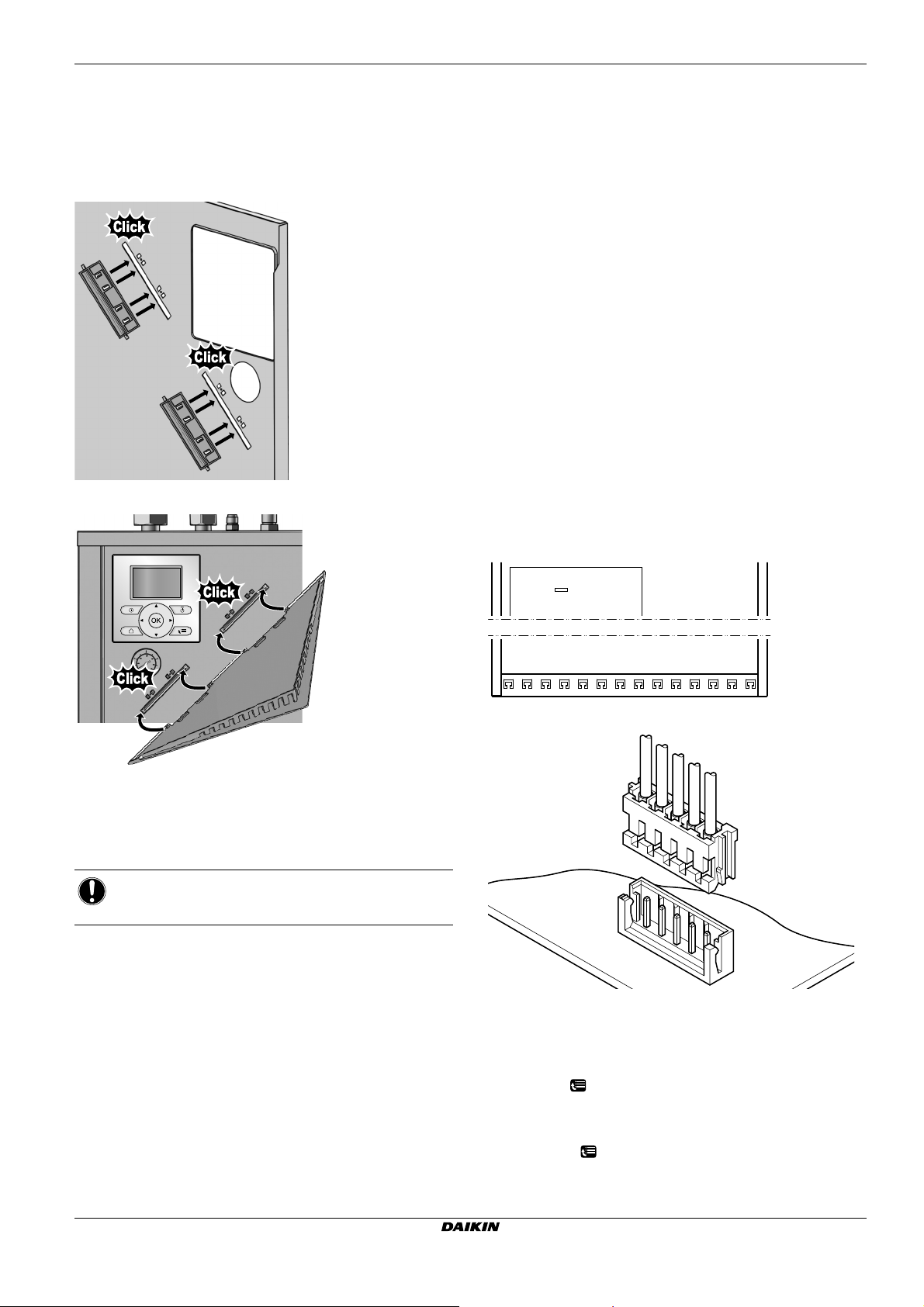
8 Configuration
2
345
H JST
7.5 Finishing the indoor unit installation
7.5.1 To fix the user interface cover to the indoor
unit
1 Make sure that the front panel is removed from the indoor unit.
See To open the indoor unit.
2 Plug the hinges into the backside of the front panel.
3 Plug the user interface cover into the hinges.
The installer can prepare the configuration off-site on PC and
afterwards upload the configuration to the system with the PC
configurator. See "8.1.1 To connect the PC cable to the switch
box" on page 30 for more information about the connection.
The configuration influences the following:
Q The calculations of the software
Q What you can see on and do with the user interface
Legend for the settings tables:
Q #: Breadcrumb in the menu structure
Q Code: Code in the overview settings
When the installer settings are changed, the system will request to
confirm. When confirmation is complete, the screen will shortly turn
OFF and "busy" will be displayed for several seconds.
The most commonly used installation settings are accessible through
the menu structure. Their location is mentioned by the breadcrumb
indication (#). Additionally, all installer settings can also be found in
Menu structure: Installer settings.
For access to the setting codes, see "To access the installer
settings" on page 30.
Not all settings are accessible through the menu structure. Some are
only accessible through their code. Then in the table explained
below, the bread crumb is set as N/A (not applicable).
8.1.1 To connect the PC cable to the switch box
1 Connect the cable with USB connection to your PC.
2 Connect the plug of the cable to X10A on A1P of the switch box
of the indoor unit.
7.5.2 To close the indoor unit
1 Close the switch box cover.
2 Reinstall the top plate.
3 Reinstall the front panel.
NOTICE
When closing the indoor unit cover, make sure that the
tightening torque does NOT exceed 4.1 N•m.
8 Configuration
8.1 Overview: Configuration
If you do NOT configure the system correctly, it might NOT work as
expected. You can configure the system with the user interface.
When you turn ON the user interface for the first time (via the indoor
unit), a quick wizard starts to help you configure the system. If
necessary, you can also make changes to the configuration
afterwards.
A1P
X10A
3 Pay special attention to the position of the plug!
8.1.2 To access the most used commands
To access the installer settings
1 Set the user permission level to Installer.
2 Go to [A]: > Installer settings.
To access the overview settings
1 Set the user permission level to Installer.
2 Go to [A.8]: > Installer settings > Overview settings.
EHVH/X16
Daikin Altherma - Low Temperature Split
4P313777-1 – 2012.05
Installer reference guide
30
Page 32

8 Configuration
To set the user permission level to Installer
1 Go to [6.4]: > Information > User permission level.
2 Press for more than 4 seconds.
Result: is displayed on the home pages.
To switch between user permission levels (End user and
Extended end user)
1 Go to [6] or any of its submenus: > Information.
2 Press for more than 5 seconds.
Result: The user permission level switches to Adv. end user.
Additional information is displayed and "+" is added to the menu
title.
3 If you do NOT press any button for more than 1 hour or press
again for more than 5 seconds, the user permission level
switches back to End user.
8.1.3 To copy the system settings from the first to
the second user interface
If an optional user interface is connected, the installer must first
proceed below instructions for the proper configuration of the two
user interfaces.
This procedure offers you also the possibility to copy the language
set from one user interface to the other one: e.g. from EKRUCAL2 to
EKRUCAL1.
1 When power is turned on for the first time, both user interfaces
display:
2 Push for 4 sec. on the user interface on which you want to
proceed to the quick wizard.
INFORMATION
During the quick wizard, the second user interface displays
Busy and will not be possible to operate.
7 Confirm the selection on the screen by pushing and all data
(languages, schedules etc.) will be synchronised from the
selected source user interface to the other one.
INFORMATION
Q During the copying, both controllers display Busy and
will not be possible to operate. Please do not power off
or disconnect the user interface.
Q The copy operation can take uptil 90 minutes.
8 Your system is now set to be operated by the two user
interfaces.
8.1.4 To copy the language set from the first to the
second user interface
See "8.1.3 To copy the system settings from the first to the second
user interface" on page 31.
8.1.5 Quick wizard: Set the system layout after
first power ON
After first power ON of the system, you are guided on the user
interface to do initial settings:
Q language,
Q date,
Q time,
Q system layout.
By confirming the system layout, you can proceed with the
installation and commissioning of the system.
1 At power ON, the quick wizard starts as long as the system
layout was NOT confirmed yet, by setting the language.
3 The quick wizard will guide you (see Quick wizard)
4 For proper operation of the system, the local data on the two
user interfaces must be the same. If this is not the case, both
user interfaces will display:
5 Select the required action:
Q Send data: the user interface you are operating contains
the correct data and the data on the other user interface will
be overwritten.
Q Receive data: the user interface you are operating doesn’t
contain the correct data and the data on the other user
interface will be used to overwrite.
6 The user interface requests confirmation if you are sure to
proceed.
Installer reference guide
31
2 Set the current date and time.
Daikin Altherma - Low Temperature Split
4P313777-1 – 2012.05
EHVH/X16
Page 33
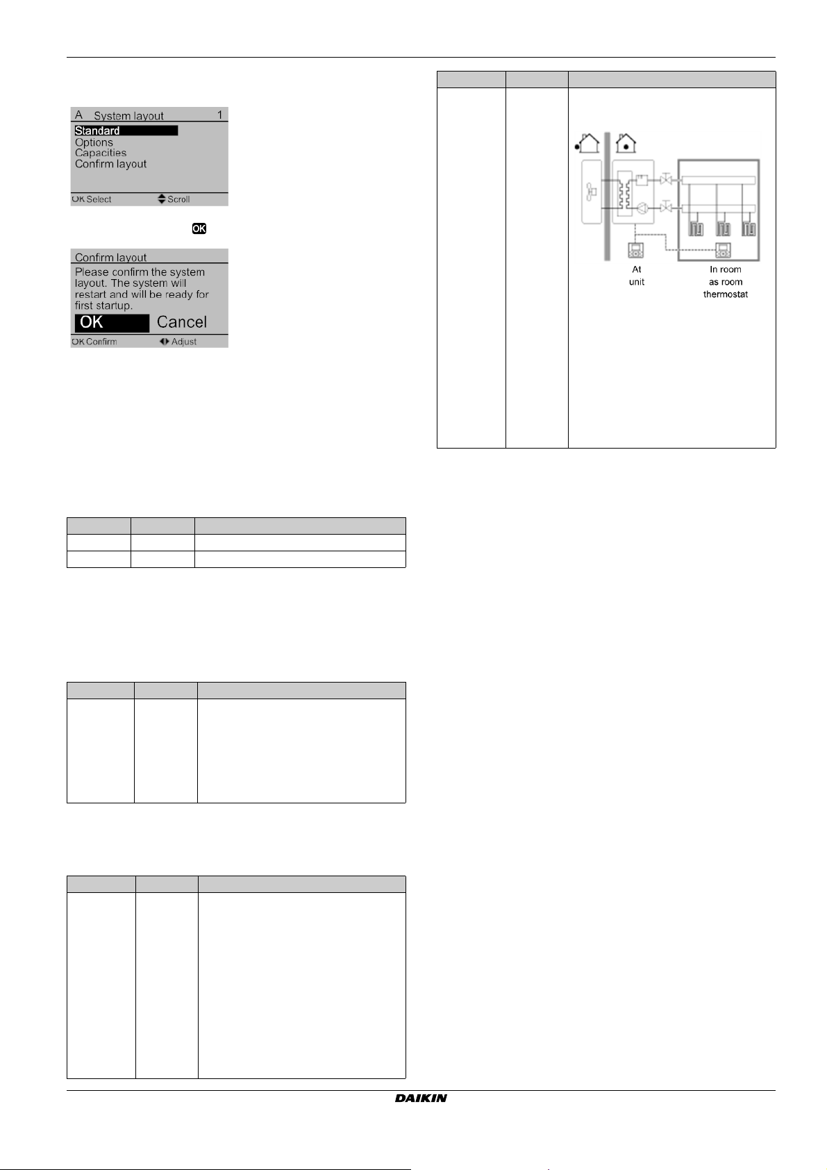
8 Configuration
3 Set the system layout settings: Standard, Options, Capacities.
For more details, see Basic configuration.
4 Confirm by pressing .
5 The user interface re-initialises and you can proceed the
installation by setting the other applicable settings and
commissioning of the system.
When the installer settings are changed, the system will request to
confirm. When confirmation is complete, the screen will shortly turn
OFF and "busy" will be displayed for several seconds.
8.2 Basic configuration
# Code Description
[A.2.1.B] N/A Only if there are 2 user interfaces (1
installed in the room, 1 installed at the
indoor unit):
User interface location:
Q At unit: the other user interface is
automatically set to In room and if
RT control is selected act as room
thermostat.
Q In room(default): the other user
interface is automatically set to At
unit and if RT control is selected to
act as room thermostat.
8.2.1 Quick wizard: Language / time and date
# Code Description
[A.1] N/A Language
[1] N/A Time and date
8.2.2 Quick wizard: Standard
Backup heater configuration (only for *9W model)
The backup heater in a *9W model is adapted to be connected to
most common European electricity grids. Besides hardware
configuration, the backup heater type must be set on the user
interface.
# Code Description
[A.2.1.5] [5-0D] BUH type:
Space heating/cooling settings
The system can heat up or cool down a space. Depending on the
type of application, the space heating/cooling settings must be made
accordingly.
# Code Description
[A.2.1.7] [C-07] Unit control method:
Q 1 (1P,(1/1+2)): 3 kW 1~ 230 V (*9W)
Q 3 (3P,(1/1+2)): 6 kW 3~ 230 V (*9W)
Q 4 (3PN,(1/2)): 6 kW 3N~ 400 V
(*9W)
Q 5 (3PN,(1/1+2)): 9 kW 3N~ 400 V
(*9W)
Q 0 (LWT control): Unit operation is
decided based on the leaving water
temperature regardless the actual
room temperature and/or heating or
cooling demand of the room.
Q 1 (Ext RT control): Unit operation is
decided by the external thermostat
or equivalent (e.g. heat pump
convector).
Q 2 (RT control): Unit operation is
decided based on the ambient
temperature of the user interface.
EHVH/X16
Daikin Altherma - Low Temperature Split
4P313777-1 – 2012.05
Installer reference guide
32
Page 34

8 Configuration
# Code Description
[A.2.1.8] [7-02] The system can supply leaving water to
up to 2 water temperature zones. During
configuration, the number of water zones
must be set.
Number of LWT zones:
Q 0 (1 LWT zone)(default): Only 1
leaving water temperature zone.
This zone is called the main leaving
water temperature zone.
Q 1 (2 LWT zones): 2 leaving water
temperature zones. The zone with
the lowest leaving water
temperature (in heating) is called
the main leaving water temperature
zone. The zone with the highest
leaving water temperature (in
heating) is called the additional
leaving water temperature zone. In
practice, the main leaving water
temperature zone consists of the
higher load heat emitters and a
mixing station is installed to achieve
the desired leaving water
temperature.
# Code Description
[A.2.1.9] [F-0D] When the space heating/cooling control
is OFF by the user interface, the pump is
always OFF. When the space
heating/cooling control is On, you can
select the desired pump operation mode
(only applicable during space
heating/cooling)
Pump operation mode:
Q 0 (Continuous): Continuous pump
operation, regardless of thermo ON
or OFF condition. Remark:
continuous pump operation requires
more energy than sample or request
pump operation.
Q 1 (Sample)(default): The pump is
ON. When there is heating or
cooling demand as the the leaving
temperature has not reached the
desired temperature yet. When
thermo OFF condition occurs, the
pump runs every 5 minutes to check
the water temperature and demand
heating or cooling if necessary.
Remark: Sample is NOT available in
extended room thermostat control or
room thermostat control.
Q 2 (Request): Pump operation based
on request. Example: Using a room
thermostat creates thermo ON/OFF
condition. When there is no such
demand, the pump is OFF. Remark:
Request is NOT available in leaving
water temperature control.
Installer reference guide
33
Daikin Altherma - Low Temperature Split
4P313777-1 – 2012.05
EHVH/X16
Page 35

8 Configuration
c
f
b
a
g
c
b
a
d f
eg
8.2.3 Quick wizard: Options
Domestic hot water settings
This chapter only applies to systems with a domestic hot water tank
installed:
Q EHBH/X: an optional domestic hot water tank is available,
Q EHVH/X: a domestic hot water tank is standard incorporated into
the indoor unit.
Following settings must be made accordingly.
# Code Description
[A.2.2.1] [E-05] DHW operation:
Q 0 (No): NOT installed. Default for
EHBH/X.
Q 1 (Yes): Installed. Default for
EHVH/X. Remark: For EHVH/X, the
domestic hot water tank is by default
installed. Do NOT change this
setting.
[A.2.2.3] [E-07] During domestic hot water preparation,
the heat pump can be assisted by an
electrical heater to ensure the domestic
hot water preparation even for high
desired tank temperatures.
DHW tank heater:
Q 0 (Horizontal BSH): Installed at side
of the tank. Default for EHBH/X.
Q 1 (Backup heater): Default for
EHVH/X. The backup heater will
also be used in domestic hot water
heating.
[A.2.2.A] [D-02] The indoor unit offers the possibility to
connect a field supplied domestic hot
water pump (On/OFF type). Depending
on the installation and configuration on
the user interface, we distinguish its
functionality.
DHW pump:
Q 0 (No)(default): NOT installed.
Q 1 (Secondary rtrn): Installed for
instant hot water when water is
tapped. The end-user sets the
operation timing (weekly schedule
time) of the domestic hot water
pump when it should run. Control of
this pump is possible through the
indoor unit.
Q 2 (Disinf. shunt): Installed for
disinfection. It runs when the
disinfection function of the domestic
hot water tank is running. No further
settings are needed.
See also illustrations below.
Domestic hot water pump installed for…
Instant hot water Disinfection
a Indoor unit
b Ta nk
c Domestic hot water pump
d Heater element
e Non-return valve
f Shower
g Cold water
Thermostats and external sensors
See "5 Application guidelines" on page 6.
# Code Description
[A.2.2.4] [C-05] Contact type main
In external room thermostat control, the
contact type of the optional room
thermostat or heat pump convector for
the main leaving water temperature zone
must be set. See "5 Application
guidelines" on page 6.
Q 1 (Thermo ON/OFF): The
connected external room thermostat
or heat pump convector sends the
heating or cooling demand by the
same signal as it is connected to
only 1 digital input (preserved for the
main leaving water temperature
zone) on the indoor unit (X2M/1).
Select this value in case of a
connection to the heat pump
convector (FWVX).
Q 2 (C/H request)(default): The
connected external room thermostat
sends separate heating and cooling
demand and is therefore connected
to the 2 digital input (preserved for
the main leaving water temperature
zone) on the indoor unit (X2M/1 and
2). Select this value in case of
connection with the wired
(EKRTWA) or wireless (EKRTR1)
room thermostat.
[A.2.2.5] [C-06] Contact type add.
In external room thermostat control with
2 leaving water temperature zones, the
type of the optional room thermostat for
the additional leaving water temperature
zone must be set. See "5 Application
guidelines" on page 6.
Q 1 (Thermo ON/OFF): See Contact
type main. Connected on the indoor
unit (X2M/1a).
Q 2 (C/H request)(default): See
Contact type main. Connected on
the indoor unit (X2M/1a and 2a).
[A.2.2.B] [C-08] External sensor
When an optional external ambient
sensor is connected, the type of the
sensor must be set. See "5 Application
guidelines" on page 6.
Q 0 (No)(default): NOT installed. The
thermistor in the user interface and
in the outdoor unit are used for
measurement.
Q 1 (Outdoor sensor): Installed. The
outdoor sensor will be used to
measure the outdoor ambient
temperature. Remark: For some
functionality, the temperature sensor
in the outdoor unit is still used.
Q 2 (Room sensor): Installed. The
temperature sensor in the user
interface is NOT used anymore.
Remark: This value has only
meaning in room thermostat control.
EHVH/X16
Daikin Altherma - Low Temperature Split
4P313777-1 – 2012.05
Installer reference guide
34
Page 36
8 Configuration
Digital I/O PCB
Modification of these settings is only needed when the optional digital
I/O PCB is installed. The digital I/O PCB has multiple functionality
which need to be configured. See "5 Application guidelines" on
page 6.
# Code Description
[A.2.2.6.1] [C-02] Ext. backup heat src
Indicates if the space heating is also
performed by means of an other heat
source that the system.
Q 0 (No)(default): NOT installed.
Q 1 (Bivalent): Installed. The auxiliary
boiler (gasboiler, oil burner) will
operate when the outdoor ambient
temperature is low. During the
bivalent operation, the heat pump is
turned OFF. Set this value in case
an auxililary boiler is used. See
"5 Application guidelines" on
page 6.
[A.2.2.6.2] [D-07] Solar kit
Only applicable for EHBH/X. Indicates if
the domestic hot water tank is also
heated by thermal solar panels.
Q 0 (No)(default): NOT installed.
Q 1 (Yes): Installed. The domestic hot
water tank can –besides by the heat
pump- also be heated by thermal
solar panels. Set this value if
thermal solar panels are installed.
See "5 Application guidelines" on
page 6.
[A.2.2.6.3] [C-09] Alarm output
Indicates the logic of the alarm output on
the digital I/O PCB during malfunctioning.
Q 0 (Normally open)(default): The
alarm output will be powered when
an alarm occurs. By setting this
value, a distinction is made between
malfunctioning and detection of a
power failure of the unit.
Q 1 (Normally closed): The alarm
output will NOT be powered when
an alarm occurs.
[A.2.2.6.4] [F-04] Bottom plate heater
Only applicable for EHBH/X16 and
EHVH/X16. Indicates if an optional
bottom plate heater is installed on the
outdoor unit. The power of the bottom
plate heater is in this case supplied by
the indoor unit.
Q 0 (No)(default): NOT installed.
Q 1 (Yes): Installed. Remark: If this
value is set, the output on the digital
I/O PCB cannot be used for space
heating/cooling output. See
"5 Application guidelines" on
page 6.
Demand PCB
The demand PCB is used to enable the power consumption control
by digital inputs. See "5 Application guidelines" on page 6.
# Code Description
[A.2.2.7] [D-04] Ext. backup heat src
Only applicable for EHBH/X04+08 and
EHVH/X04+08. Indicates if the optional
demand PCB is installed.
Q 0 (No)(default): NOT installed.
Q 1 (Yes): Installed. Power
consumption control by digital inputs
is selectable in [A.6.2.1].
Energy metering
When energy metering is performed by the use of external power
meters, configure the settings as described below. Select the pulse
frequency output of each power meter in accordance with the power
meter specifications. It is possible to connect (up to 2) power meters
with different pulse frequencies. When only 1 or no power meter is
used, select No to indicate the corresponding pulse input is NOT
used.
# Code Description
[A.2.2.8] [D-08] Optional external kWh meter 1:
Q 0 (No): NOT installed
Q 1: Installed (0.1 pulse/kWh)
Q 2: Installed (1 pulse/kWh)
Q 3: Installed (10 pulse/kWh)
Q 4: Installed (100 pulse/kWh)
Q 5: Installed (1000 pulse/kWh)
[A.2.2.9] [D-09] Optional external kWh meter 2:
Q 0 (No): NOT installed
Q 1: Installed (0.1 pulse/kWh)
Q 2: Installed (1 pulse/kWh)
Q 3: Installed (10 pulse/kWh)
Q 4: Installed (100 pulse/kWh)
Q 5: Installed (1000 pulse/kWh)
8.2.4 Quick wizard: Capacities (energy metering)
The capacities of all electrical heaters must be set for the energy
metering and/or power consumption control feature to work properly.
When measuring the resistance value of each heater, you can set the
exact heater capacity and this will lead to more accurate energy data.
# Code Description
[A.2.3.1] [6-02] Booster heater: Only applies to domestic
hot water tanks with an internal booster
heater (EKHW*) The capacity of the
booster heater at nominal voltage.
Nominal value is 3 kW. Default: 0.
0~10 kW (in steps of 0.2 kW)
[A.2.3.2] [6-03] BUH: step 1: The capacity of the first
step of the backup heater at nominal
voltage. Nominal value 3 kW. Default:
3kW.
0~10 kW (in steps of 0.2 kW)
[A.2.3.3] [6-04] BUH: step 2: Only applies to a two-step
backup heater (*9W). The capacity
difference between the second and first
step of the backup heater at nominal
voltage. Nominal value depends on the
backup heater configuration:
Q 3 kW, 1N~ 230 V: 0 kW
Q 6kW, 1N~ 230V: 3kW (6kW-3kW)
Q 6 kW, 3~ 230 V: 3 kW (6 kW-3 kW)
Q 6kW, 3N~ 400V: 3kW (6kW-3kW)
Q 9kW, 3N~ 400V: 6kW (9kW-3kW)
0~10 kW (in steps of 0.2 kW):
Q *3V: default 0 kW
Q *9V: default 6 kW
[A.2.3.6] [6-07] Bottom plate heater: Only applies to an
optional bottom plate heater
(EKBPHTH16A). The capacity of the
optional bottom plate heater at nominal
voltage. Default: 0 W.
0~200 W (in steps of 10 W)
Installer reference guide
35
Daikin Altherma - Low Temperature Split
4P313777-1 – 2012.05
EHVH/X16
Page 37

8 Configuration
[1-03]
[1-02]
T
a
T
t
[1-00] [1-01]
8.2.5 Space heating/cooling control
The basic required settings in order to configure the space
heating/cooling of your system are described in this chapter. The
weather-dependent installer settings define the parameters for the
weather-dependent operation of the unit. When weather-dependent
operation is active, the water temperature is determined
automatically depending on the outdoor temperature. Low outdoor
temperatures will result in warmer water and vice versa. During
weather-dependent operation, the user has the possibility to shift up
or down the target water temperature by a maximum of 5°C.
See the user reference guide and/or operation manual for more
details about this function.
Leaving water temperature: Main zone
# Code Description
[A.3.1.1.1] N/A LWT setpoint mode:
Q Absolute (default)
The desired leaving water
temperature is:
Q NOT weather-dependent (i.e.
does not depend on the
outdoor ambient temperature)
Q fixed in time (i.e., not
scheduled)
Q Weather dep.: The desired leaving
water temperature is:
Q weather-dependent (i.e.
depends on the outdoor
ambient temperature)
Q fixed in time (i.e., not
scheduled)
Q Abs + scheduled: The desired
leaving water temperature is:
Q NOT weather-dependent (i.e.,
does NOT depend on the
outdoor ambient temperature)
Q according a schedule. The
scheduled actions consists of
desired leaving water
temperatures either preset or
custom
Remark: This value can only
be set in leaving water
temperature control.
Q WD + scheduled: The desired
leaving water temperature is:
Q weather-dependent (i.e., does
depend on the outdoor
ambient temperature)
Q according a schedule. The
scheduled actions consists of
desired leaving water
temperatures either preset or
custom
Remark: This value can only
be set in leaving water
temperature control.
# Code Description
[A.3.1.1.3] [1-00]
Set weather-dependent heating:
[1-01]
[1-02]
[1-03]
Q T
: Target leaving water
t
temperature (main)
Q T
: Outdoor temperature
a
Q [1-00]: Low outdoor ambient
temperature. –20°C~5°C (default:
–10°C)
Q [1-01]: High outdoor ambient
temperature. 10°C~20°C (default:
15°C)
Q [1-02]: Desired leaving water
temperature when the outdoor
temperature equals or drops below
the low ambient temperature.
Between minimum and maximum
leaving water temperature (default:
40°C).
Note: This value should be higher
than [1-03] as for low outdoor
temperatures warmer water is
required.
Q [1-03]: Desired leaving water
temperature when the outdoor
temperature equals or rises above
the high ambient temperature.
Between minimum and maximum
leaving water temperature (default:
25°C).
Note: This value should be lower
than [1-02] as for high outdoor
temperatures less warm water is
required.
EHVH/X16
Daikin Altherma - Low Temperature Split
4P313777-1 – 2012.05
Installer reference guide
36
Page 38

8 Configuration
[1-09]
[1-08]
T
a
T
t
[1-06] [1-07]
# Code Description
[A.3.1.1.4] [1-06]
Set weather-dependent cooling:
[1-07]
[1-08]
[1-09]
Q T
: Target leaving water
t
temperature (main)
Q T
: Outdoor temperature
a
Q [1-06]: Low outdoor ambient
temperature. 10°C~25°C (default:
20°C)
Q [1-07]: High outdoor ambient
temperature. 25°C~43°C (default:
35°C)
Q [1-08]: Desired leaving water
temperature when the outdoor
temperature equals or drops below
the low ambient temperature.
Between minimum and maximum
leaving water temperature (default:
22°C).
Note: This value should be higher
than [1-09] as for low outdoor
temperatures less cold water
suffices.
Q [1-09]: Desired leaving water
temperature when the outdoor
temperature equals or rises above
the high ambient temperature.
Between minimum and maximum
leaving water temperature (default:
18°C).
Note: This value should be lower
than [1-08] as for high outdoor
temperatures colder water is
required.
Leaving water temperature: Additional zone
Only applicable if 2 leaving water temperature zones are present.
# Code Description
[A.3.1.2.1] N/A LWT setpoint mode:
Q Absolute (default)
The desired leaving water
temperature is:
Q NOT weather-dependent (i.e.
does not depend on the
outdoor ambient temperature)
Q fixed in time (i.e., not
scheduled)
Q Weather dep.: The desired leaving
water temperature is:
Q weather-dependent (i.e.
depends on the outdoor
ambient temperature)
Q fixed in time (i.e., not
scheduled)
Q Abs + scheduled: The desired
leaving water temperature is:
Q NOT weather-dependent (i.e.,
does NOT depend on the
outdoor ambient temperature)
Q according a schedule. The
scheduled actions are On or
OFF.
Remark: This value can only
be set in leaving water
temperature control.
Q WD + scheduled: The desired
leaving water temperature is:
Q weather-dependent (i.e., does
depend on the outdoor
ambient temperature)
Q according a schedule. The
scheduled actions are On or
OFF
Remark: This value can only
be set in leaving water
temperature control.
Installer reference guide
37
Daikin Altherma - Low Temperature Split
4P313777-1 – 2012.05
EHVH/X16
Page 39
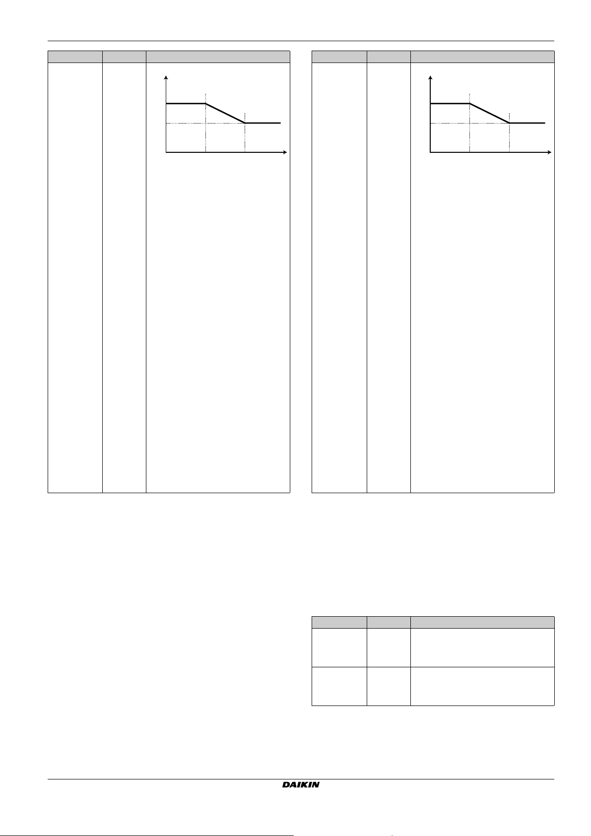
8 Configuration
[0-00]
[0-01]
T
a
T
t
[0-03] [0-02]
[1-09]
[1-08]
T
a
T
t
[1-06] [1-07]
# Code Description
[A.3.1.2.3] [0-03]
Set weather-dependent heating:
[0-02]
[0-01]
[0-00]
Q T
: Target leaving water
t
temperature (main)
Q T
: Outdoor temperature
a
Q [0-03]: Low outdoor ambient
temperature. –20°C~5°C (default:
–10°C)
Q [0-02]: High outdoor ambient
temperature. 10°C~20°C (default:
15°C)
Q [0-01]: Desired leaving water
temperature when the outdoor
temperature equals or drops below
the low ambient temperature.
Between minimum and maximum
leaving water temperature (default:
40°C).
Note: This value should be higher
than [0-00] as for low outdoor
temperatures warmer water is
required.
Q [0-00]: Desired leaving water
temperature when the outdoor
temperature equals or rises above
the high ambient temperature.
Between minimum and maximum
leaving water temperature (default:
25°C).
Note: This value should be lower
than [0-01] as for high outdoor
temperatures less warm water is
required.
# Code Description
[A.3.1.2.4] [1-06]
Set weather-dependent cooling:
[1-07]
[1-08]
[1-09]
Q T
: Target leaving water
t
temperature (main)
Q T
: Outdoor temperature
a
Q [1-06]: Low outdoor ambient
temperature. 10°C~25°C (default:
20°C)
Q [1-07]: High outdoor ambient
temperature. 25°C~43°C (default:
35°C)
Q [1-08]: Desired leaving water
temperature when the outdoor
temperature equals or drops below
the low ambient temperature.
Between minimum and maximum
leaving water temperature (default:
22°C).
Note: This value should be higher
than [1-09] as for low outdoor
temperatures less cold water
suffices.
Q [1-09]: Desired leaving water
temperature when the outdoor
temperature equals or rises above
the high ambient temperature.
Between minimum and maximum
leaving water temperature (default:
18°C).
Note: This value should be lower
than [1-08] as for high outdoor
temperatures colder water is
required.
Leaving water temperature: Delta T emitter
Temperature difference for entering and leaving water. The unit is
designed to support under floor loops operation. The recommended
leaving water temperature (set by the user interface) for under floor
loops is 35°C. In such case, the unit will be controlled to realize a
temperature difference of 5°C which means that the entering water to
the unit is around 30°C. Depending on the installed application
(radiators, heat pump convector, under floor loops) or situation, it can
be possible to change the difference between entering and leaving
water temperature. Note that the pump will regulate its flow to keep
the ∆t.
# Code Description
[A.3.1.3.1] [9-09] Heating: required temperature
difference between entering and
leaving water. Range: 3~10°C (in steps
of 1°C; default value: 5°C).
[A.3.1.3.2] [9-0A] Cooling: required temperature
difference between entering and
leaving water. Range: 3~10°C (in steps
of 1°C; default value: 5°C).
EHVH/X16
Daikin Altherma - Low Temperature Split
4P313777-1 – 2012.05
Installer reference guide
38
Page 40

8 Configuration
Leaving water temperature: Modulation
Only applicable in case of room thermostat control. When using the
room thermostat functionality, the customer needs to set the desired
room temperature. The unit will supply hot water to the heat emitters
and the room will be heated. Additionally, also the desired leaving
water temperature must be configured: when turning on the
modulation, the desired leaving water temperature will be calculated
automatically by the unit (based on the preset temperatures, if
weather-dependent is selected, modulation will be done based on the
desired weather-dependent temperatures); when turning off the
modulation, you can set the desired leaving water temperature on the
user interface. Moreover, with the modulation turned on, the desired
leaving water temperature is lowered or raised in function of the
desired room temperature and the difference between the actual and
the desired room temperature. This results in:
Q stable room temperatures exactly matching the desired
temperature (higher comfort level)
Q less On/OFF cycles (lower noise level, higher comfort and
higher efficiency)
Q water temperatures as low as possible to match the desired
temperature (higher efficiency)
# Code Description
[A.3.1.1.5] [8-05] Modulated LWT:
Q No (default): disabled.
Note: The desired leaving water
temperature needs to be set on the
user interface.
Q Yes: enabled
Note: The desired leaving water
temperature can only be read out
on the user interface
Leaving water temperature: Emitter type
Only applicable in case of room thermostat control. Depending on the
system water volume and the heat emitters type, the heat up or cool
down of a space can take longer. This setting can compensate for a
slow or a quick heating/cooling system during the heat up/cool down
cycle.
Note: The setting of the emitter type will influence the maximum
modulation of the desired leaving water temperature and the
possibility for usage of the automatic cooling/heating changeover
based on the indoor ambient temperature.
Therefore it is important to set this correctly.
# Code Description
[A.3.1.1.7] [9-0B] Emitter type:
Reaction time of the system:
Q Quick Example: Small water
volume and fan coils.
Q Slow Example: Large water
volume, floor heating loops.
8.2.6 Domestic hot water control
Only applicable in case an optional domestic hot water tank is
installed.
Configuring the desired tank temperature
The domestic hot water can be prepared in 3 different ways. They
differ from each other by the way the desired tank temperature is set
and how the unit acts upon it.
# Code Description
[A.4.1] [6-0D] To configure the desired tank temper-
ature.
Setpoint mode:
Q Reheat only: Only reheat operation
is allowed.
Note: Avoid using this setting in
case of a domestic hot water tank
without internal booster heater (risk
of capacity shortage between space
heating and domestic hot water).
Q Reheat + sched.: The domestic hot
water cylinder is reheated and also
heated up through the schedule
timer.
Q Scheduled only: The domestic hot
water tank can be heated via a
schedule.
See "8.3.2 Domestic hot water control: advanced" on page 43 for
more details
Readout the desired tank temperature
The desired tank temperature is displayed on the user interface. By
the following settings, you can configure the way the tank
temperature is displayed:
Q by its numerical value
Q by an equivalent.
Use the numerical value in case the understanding of tank
temperature is clear for the customer. On the user interface the
customer can set the desired tank temperature by 1°C. For
customers with less feeling about tank temperatures, choose display
by equivalent number of people. They will set the desired tank
temperature by indicating their domestic hot water consumption as a
number of people.
As installer, you configure the conversion between the real desired
tank temperature and the number of people taking into account the
installed tank size and the daily domestic hot water consumption of
the customer. Additionally, using the graphical display, the customer
is made aware about the amount of consumed domestic hot water.
# Code Description
[A.4.3.1] N/A How has the tank temperature to be
displayed on the user interface?
Q As temperature.
Installer reference guide
39
Q As graphic: The temperature has to
displayed as available hot water for
x persons. If you choose this, you
also have to configure which
number equals which temperature
under [A.4.4.2]: Operation day.
[A.4.3.2.1] N/A 1 person
The increment of the desired tank
temperature for 2 persons compared to 1
person. 0~20°C (default: 4°C)
Daikin Altherma - Low Temperature Split
4P313777-1 – 2012.05
EHVH/X16
Page 41

8 Configuration
# Code Description
[A.4.3.2.2] N/A 2 persons
The increment of the desired tank
temperature for 2 persons compared to 1
person. 0~20°C (default: 4°C)
[A.4.3.2.3] N/A 3 persons
The increment of the desired tank
temperature for 3 persons compared to 2
persons. 0~20°C (default: 4°C)
[A.4.3.2.4] N/A 4 persons
The increment of the desired tank
temperature for 4 persons compared to 3
persons. 0~20°C (default: 4°C)
[A.4.3.2.5] N/A 5 persons
The increment of the desired tank
temperature for 5 persons compared to 4
persons. 0~20°C (default: 4°C)
[A.4.3.2.6] N/A 6 persons
The increment of the desired tank
temperature for 6 persons compared to 5
persons. 0~20°C (default: 4°C)
Maximum tank temperature
The maximum temperature that users can select for the domestic hot
water. You can use this setting to limit the temperatures at the hot
water taps.
INFORMATION
During disinfection of the domestic hot water tank, the tank
temperature can exceed this maximum temperature.
INFORMATION
Limit the maximum hot water temperature according to the
applicable legislation.
# Code Description
[A.4.5] [6-0E] Maximum setpoint
The maximum temperature that users
can select for the domestic hot water.
You can use this setting to limit the
temperature at the hot water taps.
If
Q [E-07]=0: 40~80°C (default: 80°C)
(for EHBH in combination with
EKHW* cylinder)
Q [E-07]=1: 40~60°C (default: 60°C)
(for EHVH in combination with
EKHW* cylinder)
The maximum temperature is NOT
applicable during disinfection function.
See disinfection function.
8.2.7 Contact/helpdesk number
# Code Description
[6.3.2] N/A Number that users can call in case of
problems.
8.3 Advanced configuration/optimization
8.3.1 Space heating/cooling operation: advanced
Preset leaving water temperature
You can define preset leaving water temperature temperatures:
Q economic (denotes the desired leaving water temperature which
results in the lowest energy consumption)
Q comfort (denotes the desired leaving water temperature
temperature which results in the highest energy consumption).
Preset values make it easy to use the same value in the schedule or
to adjust the desired leaving water temperature according to the
room temperature (see modulation). If you later want to change the
value, you only have to do it in one place. Depending on whether the
desired leaving water temperature is weather dependent or not, the
absolute desired leaving water temperature should be specified or
the desired shift values.
NOTICE
The preset leaving water temperature temperatures are
only applicable for the main zone, as the schedule for the
additional zone consists of On/OFF actions.
NOTICE
Select preset leaving water temperatures in accordance
with the design and selected heat emitters to ensure the
balance between desired room and leaving water
temperatures.
# Code Description
Preset leaving water temperature for the main leaving water
temperature zone in case of NOT weather dependent
[7.4.2.1] [8-09] Comfort (heating)
[9-01]~[9-00] (default: 45°C)
[7.4.2.2] [8-0A] Eco (heating)
[9-01]~[9-00] (default: 35°C)
[7.4.2.3] [8-07] Comfort (cooling)
[9-03]~[9-02] (default: 15°C)
[7.4.2.4] [8-08] Eco (cooling)
[9-03]~[9-02] (default: 20°C)
Preset leaving water temperature (shift value) for the main leaving
water temperature zone in case of weather dependent
[7.4.2.5] N/A Comfort (heating)
–5~+5°C (default: 0°C)
[7.4.2.6] N/A Eco (heating)
–5~+5°C (default: –3°C)
[7.4.2.7] N/A Comfort (cooling)
–5~+5°C (default: 0°C)
[7.4.2.8] N/A Eco (cooling)
–5~+5°C (default: +3°C)
Temperature ranges (leaving water temperatures)
The purpose of this setting is to prevent selecting a wrong (i.e. too hot
or too cold) leaving water temperature. Thereto the available desired
heating temperature range and desired cooling temperature range
can be configured.
NOTICE
In case of a floor heating application it is important to limit
the:
Q maximum leaving water temperature at heating
operation according to the specifications of the floor
heating installation.
Q the minimum leaving water temperature at cooling
operation to 18~20°C to prevent condensation on the
floor.
EHVH/X16
Daikin Altherma - Low Temperature Split
4P313777-1 – 2012.05
Installer reference guide
40
Page 42

8 Configuration
NOTICE
Q When adjusting the leaving water temperature ranges,
all desired leaving water temperatures are also
adjusted to guarantee they are between the limits.
Q Always balance between the desired leaving water
temperature with the desired room temperature and/or
the capacity (according to the design and selection of
the heat emitters). The desired leaving water
temperature is the result of several settings (preset
values, shift values, weather dependent curves,
modulation). As a result, too high or too low leaving
water temperatures could occur which lead to
overtemperatures or capacity shortage. By limiting the
leaving water temperature range to adequate values
(depending on the heat emitter), such situations can
be avoided.
Example: Set the minimum leaving water temperature to 28°C to
avoid NOT to be able to heat up the room: leaving water
temperatures must be sufficient higher than the room temperatures
(in heating).
# Code Description
Leaving water temperature range for the main leaving water
temperature zone (= the leaving water temperature zone with the
lowest leaving water temperature in heating operation and the
highest leaving water temperature in cooling operation)
[A.3.1.1.2.2] [9-00] Maximum temp (heating)
37~depending on outdoor unit (default:
55°C)
[A.3.1.1.2.1] [9-01] Minimum temp (heating)
15~37°C (default: 25°C)
[A.3.1.1.2.4] [9-02] Maximum temp (cooling)
18~22°C (default: 22°C)
[A.3.1.1.2.3] [9-03] Minimum temp (cooling)
5~18°C (default: 5°C)
Leaving water temperature range for the additional leaving water
temperature zone (= the leaving water temperature zone with the
highest leaving water temperature in heating operation and the
lowest leaving water temperature in cooling operation)
[A.3.1.2.2.2] [9-06] Maximum temp (heating)
37~depending on outdoor unit (default:
55°C)
[A.3.1.2.2.1] [9-05] Minimum temp (heating)
15~37°C (default: 25°C)
[A.3.1.2.2.4] [9-08] Maximum temp (cooling)
18~22°C (default: 22°C)
[A.3.1.2.2.3] [9-07] Minimum temp (cooling)
5~18°C (default: 5°C)
Leaving water temperature overshoot temperature
This function defines how much the water temperature may rise
above the desired leaving water temperature before the compressor
stops. The compressor will startup again when the leaving water
temperature drops below the desired leaving water temperature. This
function is only applicable in heating mode.
Leaving water temperature compensation around 0°C
In heating operation, the desired leaving water temperature is locally
increased around an outdoor temperature of 0°C. This compensation
can be selected when using an absolute or a weather dependent
desired temperature, this compensation can be selected (see
illustration below). Use this setting to compensate for possible heat
losses of the building when the outdoor temperature is around 0°C
(e.g. in cold region countries).
# Code Description
N/A [D-03] 0 (disabled) (default)
1 (enabled) L=2°C, R=4°C
(–2°C<T
<2°C)
A
2 (enabled) L=4°C, R=4°C
(–2°C<T
<2°C)
A
3 (enabled) L=2°C, R=8°C
(–4°C<T
<4°C)
A
4 (enabled) L=4°C, R=8°C
(–4°C<T
<4°C)
A
Leaving water temperature maximum modulation
Only applicable in room thermostat control and when modulation is
enabled. The maximum modulation (=variance) on the desired
leaving water temperature decided on the difference between the
actual and desired room temperature, e.g. 3°C modulation means the
desired leaving water temperature can be increased or lowered by
3°C. Increasing the modulation results in better performance (less
On/OFF, faster heat up), but note that depending on the heat emitter,
there must always be a balance (refer to the design and selection of
the heat emitters) between the desired leaving water temperature
and the desired room temperature.
# Code Description
N/A [8-06] 1~5°C (default: 3°C)
Weather dependent cooling allowance
Only applicable for EHBX and EHVX. It is possible to disable weather
dependent cooling, meaning the desired leaving water temperature in
cooling operation doesn’t depend on the outdoor ambient
temperature and this regardless whether weather dependent is
selected or NOT. Both for the main leaving water temperature zone
as for the additional leaving water temperature zone, this can be set
separately.
# Code Description
N/A [1-04] Weather dependent cooling of the main
leaving water temperature zone is…
0 (disabled) (default)
1 (enabled)
N/A [1-05] Weather dependent cooling of the
additional leaving water temperature
zone is…
0 (disabled) (default)
1 (enabled)
# Code Description
N/A [9-04] 1~4°C (default: 1°C)
Installer reference guide
41
Daikin Altherma - Low Temperature Split
4P313777-1 – 2012.05
EHVH/X16
Page 43

8 Configuration
Temperature ranges (room temperature)
Only applicable in room thermostat control. In order to save energy
by preventing overheating or undercooling the room, you can limit the
range of the room temperature, both for heating and/or cooling.
NOTICE
When adjusting the room temperature ranges, all desired
room temperatures are also adjusted to guarantee they are
between the limits.
# Code Description
Room temp. range
[A.3.2.1.2] [3-06] Maximum temp (heating)
18~30°C (default: 30°C)
[A.3.2.1.1] [3-07] Minimum temp (heating)
12~18°C (default: 12°C)
[A.3.2.1.4] [3-08] Maximum temp (cooling)
25~35°C (default: 35°C)
[A.3.2.1.3] [3-09] Minimum temp (cooling)
15~25°C (default: 15°C)
Room temperature step
Only applicable in room thermostat control and when the temperature
is displayed in °C.
# Code Description
[A.3.2.4] [3-06] Room temp. step
Q 1°C (default). The desired room
temperature on the user interface is
settable per 1°C.
Q 0.5°C The desired room
temperature on the user interface is
settable per 0.5°C. The actual room
temperature is displayed with an
accuracy of 0.1°C.
Room temperature hysteresis
Only applicable in case of room thermostat control. The hysteresis
band around the desired room temperature is settable. Daikin
advises NOT to change the room temperature hysteresis as it is set
for an optimal use of the system.
Room frost protection
Only applicable in case of room thermostat control. When the actual
room temperature would drop below the room frost temperature, the
unit will supply leaving water (in heating operation mode) to the heat
emitters to heat up the room again.
NOTICE
Even if the room thermostat control is OFF on the user
interface, room frost protection remains active.
# Code Description
N/A [2-06] Room frost protection
0: disabled
1: enabled (default)
N/A [2-05] Room antifrost temperature
4~16°C (default: 12°C)
Shut-off valve
Only applicable in case of 2 leaving water temperature zones.
The shut-off valve, which is in the main leaving water temperature
zone, output is configurable.
INFORMATION
During defrost operation, the shut-off valve is always
opened.
Thermo On/OFF: the valve closes, depending on [F-0B] when there
is no heating and/or demand of the room in the main zone. Enable
this setting to:
Q avoid leaving water supply to the heat emitters in the main LWT
zone (through the mixing valve station) when there is request
from the additional LWT zone.
Q activate the On/OFF pump of the mixing valve station only when
there is demand (see application guidelines). See "5 Application
guidelines" on page 6.
# Code Description
[A.3.1.1.6.1] [F-0B] The shut-off valve:
0 (No): is NOT influenced by heating or
cooling demand.
1 (Yes)(default): closes when there is
heating or cooling demand.
Cooling: Only applicable for EHBX and EHVX. The shut off valve
closes, depending on [F-0C] when the unit is running in cooling
operation mode. Enable this setting to avoid cold leaving water
through the heat emitter and the forming of condensation (e.g. under
floor heating loops or radiators).
# Code Description
N/A [9-0C] 1~6°C (default: 1°C)
Room temperature offset
Only applicable in case of room thermostat control. You can calibrate
the (external) room temperature sensor. It is possible to give an offset
to the room thermistor value measured by the user interface or by the
external room sensor. The settings can be used to compensate for
situations where the user interface or external room sensor cannot be
installed on the ideal installation location (see installation manual
and/or installer reference guide).
# Code Description
Room temp. offset: Offset on the actual room temperature
measured on the user interface sensor.
[A.3.2.2] [2-0A] –5~5°C, step 0.1°C (default: 0°C)
Ext. room sensor offset: Only applicable if the external room sensor
option is installed and configured (see [C-08])
[A.3.2.3] [2-09] –5~5°C, step 0.1°C (default: 0°C)
EHVH/X16
Daikin Altherma - Low Temperature Split
4P313777-1 – 2012.05
# Code Description
[A.3.1.1.6.2] [F-0C] The shut-off valve:
0 (No)(default): is NOT influenced by
changing the space operation mode to
cooling.
1 (Yes): closes when the space
operation mode is cooling.
Operation range
Depending on the average outdoor temperature, the operation of the
unit in space heating or space cooling is prohibited.
Space heating OFF temp: When the averaged outdoor temperature
raises above this value, space heating is turned OFF to avoid
overheating.
# Code Description
[A.3.3.1] [4-02]
Q EHBH/X04+08 and EHVH/X04+08:
14~25°C (default: 25°C)
Q EHBH/X16 and EHVH/X16:
14~35°C (default: 35°C)
The same setting is also used in
automatic heating/cooling changeover.
Installer reference guide
42
Page 44

8 Configuration
Space cooling On temp: Only applicable for EHBX and EHVX. When
the averaged outdoor temperature drops below this value, space
ooling is turned OFF.
# Code Description
[A.3.3.2] [F-012] 10~35°C (default: 20°C)
The same setting is also used in
automatic heating/cooling changeover.
Automatic heating/cooling changeover
Only applicable for EHBX and EHVX. The end-user sets the
desired operation mode on the user interface: Heating, Cooling or
Automatic (see also operation manual/user reference guide). When
Automatic is selected, the changing of the operation mode is based
on:
Q Monthly allowance for heating and/or cooling: the end-user
indicates on a monthly base which operation is allowed (# [7:5]):
both heating/cooling or heating only or cooling only. If the
allowed operation mode changes to cooling only, the operation
mode changes to cooling. If the allowed operation mode
changes to heating only, the operation mode changes to
heating.
Q Averaged outdoor temperature: the operation mode will be
changed in order to always be within range determined by the
space heating OFF temperature for heating and the space
cooling On temperature for cooling. If the outdoor temperature
drops, the operation mode switches to heating and vice versa.
Note that the outdoor temperature will be time-averaged (see
"8 Configuration" on page 30).
When the outdoor temperature is between the space cooling On and
the space heating OFF temperature, the operation mode remains
unchanged unless the system is configured in room thermostat
control with one leaving water temperature zone and quick heat
emitters. In that case, the operation mode will change based on:
Q Measured indoor temperature: besides the heating and the
cooling desired room temperature, the installer sets a hysteresis
value (e.g. when in heating, this value is related to the desired
cooling temperature) and an offset value (e.g. when in heating,
this value is related to the desired heating temperature).
Example: the desired room temperature in heating is 22°C and
in cooling 24°C, with a hysteresis value of 1°C and an offset of
4°C. Changeover from heating to cooling will occur when the
room temperature raises above the maximum of the desired
cooling temperature added by the hysteresis value (thus 25°C)
and the desired heating temperature added by the offset value
(thus 26°C). Oppositely, changeover from cooling to heating will
occur when the room temperature drops below the minimum of
the desired heating temperature subtracted by the hysteresis
value (thus 21°C) and the desired cooling temperature
subtracted by the offset value (thus 20°C).
Q Guard timer to prevent too frequent changing from heating to
cooling and vice versa.
Changeover settings related to the outdoor temperature (only when
automatic is selected):
# Code Description
[A.3.3.1] [4-02] Space heating OFF temp. If the outdoor
temperature raises above this value, the
operation mode will change to cooling:
Q EHBH/X04+08 and EHVH/X04+08:
14~25°C (default: 25°C)
Q EHBH/X16 and EHVH/X16:
14~35°C (default: 35°C)
[A.3.3.2] [F-01] Space cooling On temp. If the outdoor
temperature drops below this value, the
operation mode will change to heating:
10~35°C (default: 20°C)
Changeover settings related to the indoor temperature. Only
applicable when Automatic is selected and the system is configured
in room thermostat control with 1 leaving water temperature zone
and quick heat emitters.
# Code Description
N/A [4-0B] Hysteresis: Ensures that changeover is
only done when necessary. Example: the
space operation mode only changes
from cooling to heating when the room
temperature drops below the desired
heating temperature subtracted by the
hysteresis.
1~10°C, step 0.5°C (default: 1°C)
N/A [4-0D] Offset: Ensures that the active desired
room temperature can be reached.
Example: if heating to cooling
changeover would occur below the
desired room temperature in heating, this
desired room temperature could never
be reached.
1~10°C, step 0.5°C (default: 1°C)
N/A [4-0E] Guard timer: Minimum time that the
system runs in a certain space operation
mode. This prevents too frequent
changeover between heating and cooling
mode.
0~120 minutes, step 15 minutes (default:
30 minutes)
8.3.2 Domestic hot water control: advanced
Preset tank temperatures
Only applicable when domestic hot water preparation is scheduled or
scheduled + reheat.
You can define preset tank temperatures:
Q storage economic
Q storage comfort
Q reheat
Preset values make it easy to use the same value in the schedule. If
you later want to change the value, you only have to do it in 1 place
(see also operation manual and/or user reference guide).
Storage comfort: Only applicable if the desired tank temperature is
NOT weather dependent. The storage comfort temperature denotes
the higher desired tank temperature, where the tank heat up cycle is
prioritized till the reheat set point. It is the desired temperature when
a storage comfort action is scheduled (preferably during night).
# Code Description
[7.4.3.1] [6-0A] 30~80°C (default: 60°C)
Storage eco: The storage economic temperature denotes the lower
desired tank temperature. It is the desired temperature when a
storage economic action is scheduled (preferably during day).
# Code Description
[7.4.3.2] [6-0B] 30~80°C (default: 45°C)
Reheat: The desired reheat tank temperature is used:
Q in scheduled + reheat mode, as guaranteed minimum tank
temperature: if the tank temperature drops below this value, the
tank is heated up.
Q during storage comfort, to prioritize the domestic hot water
preparation. When the tank temperature raises above this value,
domestic hot water preparation and space heating/cooling are
executed sequentially.
# Code Description
[7.4.3.3] [6-0C] 30~50°C (default: 45°C)
Installer reference guide
43
Daikin Altherma - Low Temperature Split
4P313777-1 – 2012.05
EHVH/X16
Page 45
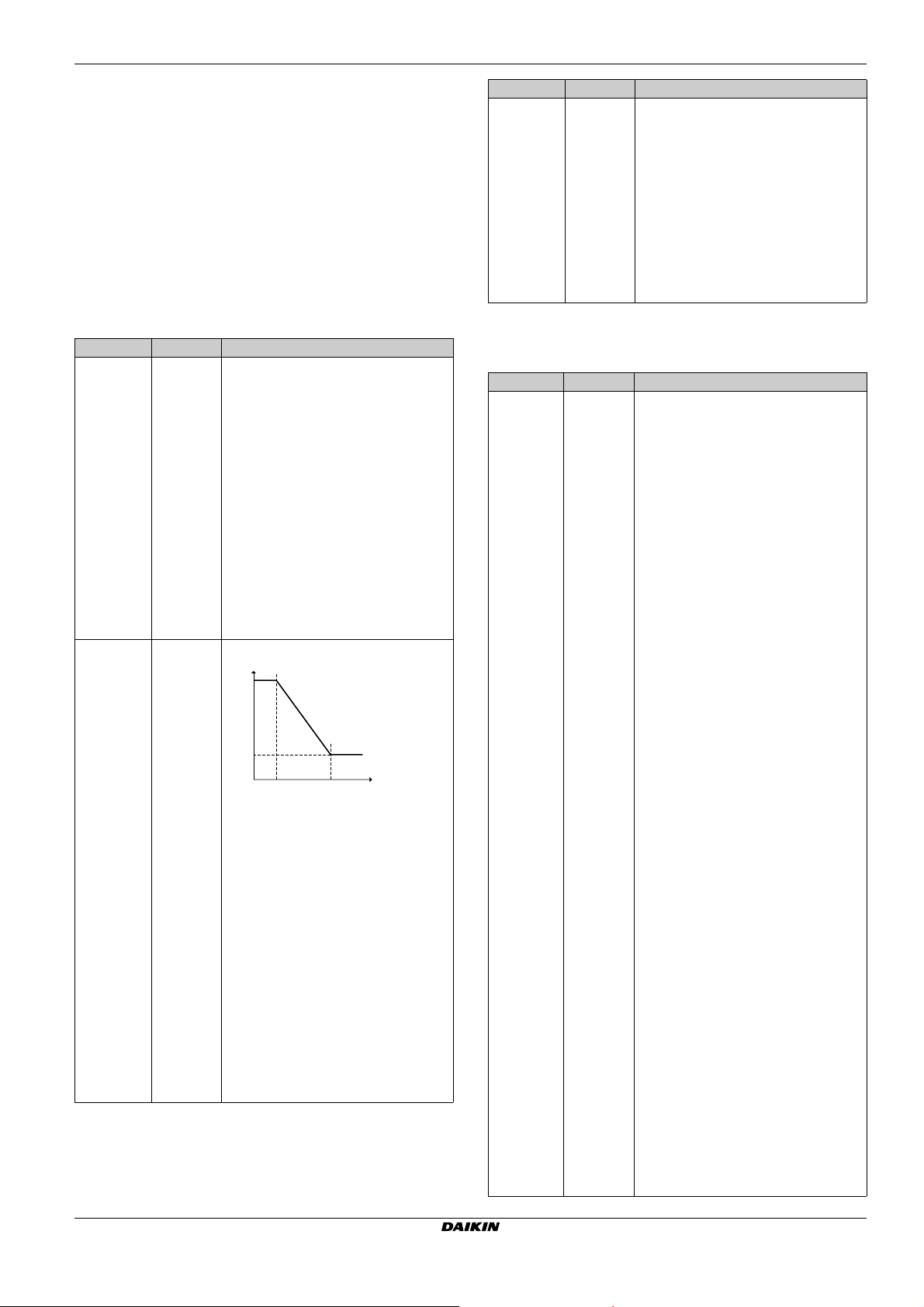
8 Configuration
T
DHW
T
a
[0-0C]
[0-0B]
[0-0E] [0-0D]
Weather dependent
The weather dependent installer settings define the parameters for
the weather dependent operation of the unit. When weather
dependent operation is active the desired tank temperature is
determined automatically depending on the averaged outdoor
temperature: low outdoor temperatures will result in higher desired
tank temperatures as the cold water tap is colder and vice versa. In
case of scheduled or scheduled+reheat domestic hot water
preparation, the storage comfort temperature is weather dependent
(according to the weather dependent curve), the storage economic
and reheat temperature are NOT weather dependent. In case of
reheat only domestic hot water preparation, the desired tank
temperature is weather dependent (according to the weather
dependent curve). During weather dependent operation, the enduser cannot adjust the desired tank temperature on the user
interface.
# Code Description
[A.4.2.2] N/A Weather dependent desired tank
temperature is:
Q Absolute (default): disabled. All
desired tank temperature are NOT
weather dependent.
Q Weather dep.: enabled. In
scheduled or scheduled+reheat
mode, the storage comfort
temperature is weather dependent.
Storage economic and reheat
temperatures are NOT weather
dependent. In reheat mode, the
desired tank temperature is weather
dependent.
Note: When the displayed tank
temperature is weather dependent,
it cannot be adjusted on the user
interface.
[A.4.2.3] [0-0E]
Weather-dependent curve
[0-0D]
[0-0C]
[0-0B]
T
: The desired tank temperature.
DHW
: The (averaged) outdoor ambient
T
a
temperature
Q [0-0E]: low outdoor ambient
temperature. –20~5°C (default: –
10°C)
Q [0-0D]: high outdoor ambient
temperature: 10~20°C (default:
15°C)
Q [0-0C]: desired tank temperature
when the outdoor temperature
equals or drops below the low
ambient temperature: 55~70°C
(default: 70°C)
Q [0-0B]: desired tank temperature
when the outdoor temperature
equals or rises above the high
ambient temperature: 35~55°C
(default: 55°C)
# Code Description
[A.4.2.1] N/A Schedule temperatures
The possible actions of the tank
temperature are:
Q Presets (default): the predefined
temperatures storage comfort,
storage economic, and storage
stop. The predefined temperature
are set in the menu structure.
Q
Custom: custom temperatures within
the allowable range and storage stop.
Note: When selecting this value, it is
NOT possible to select weather
dependent tank temperatures.
Booster heater and heat pump operation
For systems with separate domestic hot water tank (only for
EHBH/X)
# Code Description
N/A [4-03] Defines the operation permission of the
booster heater depending on ambient,
domestic hot water temperature or
operation mode of heat pump. This
setting is only applicable in reheat mode
for applications with separate domestic
hot water tank.
Q
0: Booster heater operation is NOT
allowed except for "Disinfection
function" and "Powerful domestic
water heating".
Only use this in case the capacity of
the heat pump can cover the heating
requirements of the house and
domestic hot water over the complete
heating season.
If the outdoor temperature is below
setting [5-03] and [5-02]=1, the
domestic hot water will not be heated.
The domestic hot water temperature
can be maximum the heat pump OFF
temperature.
Q 1: Booster heater operation is
allowed when required.
Q
2: The booster heater is allowed
outside the operation range of the heat
pump for domestic hot water operation.
Booster heater operation is only
allowed if:
Q Ambient temperature is out of
the operating range: T
>35°C, OR
or T
Q
a
Domestic hot water temperature
<[5-03]
a
is 2°C lower than the heat pump
OFF temperature.
The booster heater will be allowed to
operate when T
<[5-03] independent of
a
the status of [5-02].
If bivalent operation is enabled and
permission signal for auxiliary boiler is
ON, the booster heater will be restricted
even when T
Q 3: The booster heater is allowed
<[5-03]. See [C-02].
a
when the heat pump is NOT active
in domestic hot water operation.
Same as setting 1, but simultaneous
heat pump domestic hot water
operation and booster heater
operation is not allowed.
When setting [4-03]=1/2/3, the booster
heater operation can still be restricted by
the booster heater allowance schedule.
EHVH/X16
Daikin Altherma - Low Temperature Split
4P313777-1 – 2012.05
Installer reference guide
44
Page 46

8 Configuration
# Code Description
N/A [7-00] Overshoot temperature. Temperature
difference above the domestic hot water
set point temperature before the booster
heater is turned OFF. The domestic hot
water tank temperature will increase with
[7-00] above selected temperature
set point.
N/A [7-01] Hysteresis. Temperature difference
between booster heater ON and booster
heater OFF temperature. The minimum
hysteresis temperature is 2°C.
N/A [6-00] The temperature difference determining
the heat pump ON temperature.
N/A [6-01] The temperature difference determining
the heat pump OFF temperature.
Timers
# Code Description
N/A [8-00] Minimum running time for domestic hot
water operation. During this time, space
heating/cooling is NOT allowed, even
when the target domestic hot water
temperature has been reached.
N/A [8-01] Maximum running time for domestic hot
water operation. Domestic hot water
heating stops even when the target
domestic hot water temperature is NOT
reached. The actual maximum running
time also depends on setting [8-04].
Q When system layout = Room
thermostat control: This preset value
is only taken into account if there is
a request for space heating or
cooling. If there is NO request for
space heating/cooling, the tank is
heated until heat pump OFF
temperature.
Q When system layout ≠ Room
thermostat control: This preset value
is always taken into account.
N/A [8-02] Anti-recycling time.
Minimum time between two cycles for
domestic hot water. The actual antirecycling time also depends on setting
[8-04].
# Code Description
N/A [8-03] Booster heater delay timer.
Only for EKHW*
Start-up delay time for the booster heater
when domestic hot water mode is active.
Q When domestic hot water mode is
NOT active, the delay time is
20 minutes.
Q The delay time starts from booster
heater ON temperature.
Q By adapting the booster heater
delay time versus the maximum
running time, you can find an
optimal balance between the energy
efficiency and the heat up time.
Q If the booster heater delay time is
set too high, it might take a long time
before the domestic hot water
reaches its set temperature.
Q The setting [8-03] is only meaningful
if setting [4-03]=1. Setting [403]=0/2/3 limits the booster heater
automatically in relation to
heat pump operation time in
domestic water heating mode.
Q Make sure that [8-03] is always in
relation with the maximum running
time [8-01].
N/A [8-04] Additional running time for the maximum
running time depending on the outdoor
temperature [4-02] or [F-01].
Disinfection
Applies only to installations with a domestic hot water tank.
The disinfection function disinfects the domestic hot water tank by
periodically heating the domestic hot water to a specific temperature.
CAUTION
The disinfection function settings must be configured by the
installer according to the applicable legislation.
# Code Description
[A.4.4.2] [2-00] Operation day:
Q Each day
Q Monday
Q Tuesday
Q Wednesday
Q Thursday
Q Friday
Q Saturday
Q Sunday
[A.4.4.2] [2-01] Disinfection
Q No
Q Yes
[A.4.4.3] [2-02] Start time: 00~23:00, step: 1:00.
[A.4.4.4] [2-03] Temperature target:
Q With booster heater: 55~80°C,
default: 70°C.
Q Without booster heater: 60°C
(fixed).
[A.4.4.5] [2-04] Duration:
Q With booster heater: 5~60 minutes,
default: 10 minutes.
Q Without booster heater: 40~60
minutes, default: 60 minutes.
Installer reference guide
45
Daikin Altherma - Low Temperature Split
4P313777-1 – 2012.05
EHVH/X16
Page 47

T
00.00 22.00 24.0001.00 23.00 t
T
DHW
T
H
T
U
[2-02]
[2-03]
[2-04]
Domestic hot water temperature
DHW
T
User set point temperature
U
T
High set point temperature [2-03]
H
t Time
WARNING
Be aware that the domestic hot water temperature at the
hot water tap will be equal to the value selected in field
setting [2-03] after a disinfection operation.
When the high domestic hot water temperature can be a
potential risk for human injuries, a mixing valve (field
supply) shall be installed at the hot water outlet connection
of the domestic hot water tank. This mixing valve shall
secure that the hot water temperature at the hot water tap
never rise above a set maximum value. This maximum
allowable hot water temperature shall be selected
according to the applicable legislation.
8 Configuration
# Code Description
[A.5.1.1] [4-00] Backup heater operation:
Q 0: Disabled
Q 1: Enabled
Q 2: Limited, only enabled during
domestic hot water operation of for
system with integrated domestic hot
water tank.
[A.5.1.2] [4-06] Defines if during emergency operation
the backup heater is:
Q 1: Allowed
Q 0: NOT allowed
Emergency operation will startup backup
heater operation during certain outdoor
malfunctions.
[A.5.1.3] [4-07] Defines whether backup heater second
step is:
Q 1: Allowed
Q 0: NOT allowed
In this way it is possible to limit the
backup heater capacity.
N/A [5-00] Is backup heater operation allowed
above equilibrium temperature during
space heating operation?
Q 1: NOT allowed
Q 0: Allowed
[A.5.1.4] [5-01] Equilibrium temperature.
Outdoor temperature below which
operation of the backup heater is
allowed.
CAUTION
Be sure that the disinfection function start time [A.4.4.3]
with defined duration [A.4.4.5] is NOT interrupted by
possible domestic hot water demand.
INFORMATION
Disinfection function is restarted in case the domestic hot
water temperature drops 5°C below the disinfection target
temperature within the duration time.
8.3.3 Heat source settings
Backup heater
For systems without domestic hot water tank or with separate
domestic hot water tank (only for EHBH/X)
Backup heater operation mode: defines when backup heater
operation is enabled or disabled. This setting is only overruled when
backup heating is required during defrost operation or malfunctioning
of the outdoor unit (when [A.5.1.2] [4-06] is enabled)
For systems with an integrated domestic hot water tank (only for
EHVH/X)
Backup heater operation mode: defines when backup heater
operation is disabled or only allowed during domestic hot water
operation. This setting is only overruled when backup heating is
required during defrost operation or malfunctioning of the outdoor unit
(when [A.5.1.2] [4-06] is enabled)
INFORMATION
Only for systems with integrated domestic hot water tank: If
the storage temperature set point is higher than 50°C,
Daikin recommends NOT to disable the backup heater
second step because it will have a big impact on the
required time for the unit to heat up the domestic hot water
tank.
Bivalent
Applies only to installations with an auxiliary boiler (alternating
operation, parallel connected). The purpose of this function is to
determine — based on the outdoor temperature — which heating
source can/will provide the space heating, either the Daikin indoor
unit or an auxiliary boiler.
The field setting "bivalent operation" apply only the indoor unit space
heating operation and the permission signal for the auxiliary boiler.
When the "bivalent operation" function is enabled, the indoor unit will
stop automatically in space heating operation when the outdoor
temperature drops below "bivalent ON temperature" and the
permission signal for the auxiliary boiler becomes active.
When the bivalent operation function is disabled, the space heating
by indoor unit is possible at all outdoor temperatures (see operation
ranges) and permission signal for auxiliary boiler is always
disactivated.
Q [C-03] Bivalent ON temperature: defines the outdoor
temperature below which the permission signal for the auxiliary
boiler will be active (closed, KCR on EKRP1HB) and space
heating by indoor unit will be stopped.
EHVH/X16
Daikin Altherma - Low Temperature Split
4P313777-1 – 2012.05
Installer reference guide
46
Page 48

8 Configuration
Q [C-04] Bivalent hysteresis: defines the temperature difference
between bivalent ON temperature and bivalent OFF
temperature.
Permission signal X1–X2 (EKRP1HB)
TAOutdoor temperature
CAUTION
Make sure to observe all rules mentioned in application
guideline 5 when bivalent operation function is enabled.
Daikin shall not be held liable for any damage resulting
from failure to observe this rule.
INFORMATION
Q The combination of setting [4-03]=0/2 with bivalent
operation at low outdoor temperature can result in
domestic hot water shortage.
Q The bivalent operation function has no impact on the
domestic water heating mode. The domestic hot water
is still and only heated by the indoor unit.
Q The permission signal for the auxiliary boiler is located
on the EKRP1HB (digital I/O PCB). When it is
activated, the contact X1, X2 is closed and open when
it is disactivated. See illustration below for the
schematic location of this contact.
X1 X2 X3 X4
X2M
OFF ON
SS1
Bottom plate heater
Applies only to installation with an outdoor unit ERHQ and the option
bottom plate heater kit is installed.
Q [F-02] Bottom plate heater ON temperature: defines the outdoor
temperature below which the bottom plate heater will be
activated by indoor unit in order to prevent ice build-up in the
bottom plate of the outdoor unit at lower outdoor temperatures.
Q [F-03] Bottom plate heater hysteresis: defines the temperature
difference between bottom plate heater ON temperature and the
bottom plate heater OFF temperature.
Bottom plate heater
TAOutdoor temperature
CAUTION
The bottom plate heater is controlled via EKRP1HB.
# Code Description
N/A [F-02] Bottom plate heater ON temperature:
3~10°C
Default: 3°C
N/A [F-03] Hysteresis: 2~5°C
Default: 5°C
INFORMATION
Dependent from setting [F-04] contact Y2 located on digital
I/O PCB (EKRP1HB) controls the option bottom plate
heater. See illustration below for the schematic location of
this contact. For complete upwiring, see wiring diagram.
X1 X2 X3 X4
X2M
OFF ON
X1M
YC Y1 Y2 Y3 Y4
# Code Description
N/A [C-03] ON temperature.
If the outdoor temperature drops below
this temperature, the bivalent heat
source permission signal will be active.
N/A [C-04] Hysteresis.
Temperature difference between bivalent
heat source ON and OFF to prevent too
much switching.
SS1
X1M
YC Y1 Y2 Y3 Y4
Installer reference guide
47
Daikin Altherma - Low Temperature Split
4P313777-1 – 2012.05
EHVH/X16
Page 49

8 Configuration
8.3.4 System settings
Priorities
For systems with separate domestic hot water tank (only for
EHBH/X)
# Code Description
N/A [5-02] Space heating priority.
Defines whether domestic hot water is
made by booster heater only when
outdoor temperature is below space
heating priority temperature.
Q 0: disabled
Q 1: enabled
[5-01] Equilibrium temperature and [503] Space heating priority temperature
are related to backup heater. So, you
must set [5-01] and [5-03] to the same
value.
[5-03] Space heating priority temperature.
Defines the outdoor temperature which
below the domestic hot water will be
heated by booster heater only.
N/A [5-04] Set point correction for domestic hot
water temperature: set point correction
for the desired domestic hot water
temperature, to be applied at low
outdoor temperature when space
heating priority is enabled. The
corrected (higher) set point will make
sure that the total heat capacity of the
water in the tank remains
approximately unchanged, by
compensating for the colder bottom
water layer of the tank (because the
heat exchanger coil is not operational)
with a warmer top layer.
[A.6.1.2] [C-00] If a solar kit is installed, what has
priority to heat up the tank?
Q 0: Solar kit
Q 1: Heat pump
[A.6.1.1.1] [C-01] If there is a simultaneous demand for
space heating/cooling and domestic hot
water heating (by heat pump), which
operation mode has priority?
Q 0: The operation mode with the
highest request has priority.
Q 1: Always space heating/cooling
has priority.
# Code Description
N/A [5-03] Space heating priority temperature.
Defines the outdoor temperature which
below the backup heater will assist
during domestic hot water heating.
[A.6.1.2] [C-00] If a solar kit is installed, what has
priority to heat up the tank?
Q 0: Solar kit
Q 1: Heat pump
[A.6.1.1.1] [C-01] If there is a simultaneous demand for
space heating/cooling and domestic hot
water heating (by heat pump), which
operation mode has priority?
Q 0: The operation mode with the
highest request has priority.
Q 1: Always space heating/cooling
has priority.
Auto-restart
When power returns after a power supply failure, the auto restart
function reapplies the remote controller settings at the time of the
power failure. Therefore, Daikin recommends to always enable the
function.
If the preferential kWh rate power supply is of the type that power
supply is interrupted, always enable the auto restart function.
Continuous indoor unit control can be guaranteed independent of the
preferential kWh rate power supply status, by connecting the indoor
unit to a normal kWh rate power supply.
# Code Description
[A.6.1] [3-00] Auto restart function:
Q 0: Enabled
Q 1: Disabled
Preferential kWh rate power supply
# Code Description
[A.6.2.1] [d-00] Which heaters are allowed to operate
during preferential kWh rate power
supply?
Q 0 (default): None
Q 1: Booster heater only
Q 2: Backup heater only
Q 3: All heaters
Only for EHBH + EKHW*: See table
below.
Only for EHVH: See table below.
For systems with an integrated domestic hot water tank (only for
EHVH/X)
# Code Description
N/A [5-02] Space heating priority.
Defines whether backup heater will
assist the heat pump during domestic
hot water operation.
Consequence: Shorter tank heating
operation time and shorter interruption
of the space heating cycle.
This setting MUST always be 1.
[5-01] Equilibrium temperature and [5-
03] Space heating priority temperature
are related to backup heater. So, you
must set [5-01] and [5-03] to the same
value.
If the backup heater operation is limited
([4-00]=0) and the outdoor temperature
is lower than setting [5-03], the
domestic hot water will not be heated
with the backup heater.
EHVH/X16
Daikin Altherma - Low Temperature Split
4P313777-1 – 2012.05
Settings 1, 2 and 3 are only meaningful if
the preferential kWh rate power supply is
of type 1 or indoor unit is connected to a
normal kWh rate power supply (via 30-31
X2M) and the backup heater and booster
heater are NOT connected to the
preferential kWh rate power supply.
Only for EHBH + EKHW*:
[d-00] Booster heater Backup heater Compressor
0 (default) Forced OFF Forced OFF Forced OFF
1 Permitted
2 Forced OFF Permitted
3 Permitted
Only for EHVH: Do NOT use 1 or 3.
[d-00] Backup heater Compressor
0 (default) Forced OFF Forced OFF
2 Allowed
Installer reference guide
48
Page 50

8 Configuration
Power saving function
INFORMATION
Only applicable for ERLQ004~008CAV3.
Defines whether the outdoor unit power supply can be interrupted
(internally by indoor unit control) during stand-still conditions (no
space heating/cooling nor domestic hot water demand). The final
decision to allow power interruption of the outdoor unit during
standstill depends on the ambient temperature, compressor
conditions and minimum internal timers.
To enable the power saving function setting, [E-08] needs to be
enable at the user interface in combination with the removal of the
power saving connector at the outdoor unit. The power saving
connector at the outdoor unit shall only be removed when the main
power supply to the application is switched OFF.
3x
123
# Code Description
N/A [E-08] Power saving function for outdoor unit:
Q 0 (default): Disabled
Q 1: Enabled
Power consumption control
Only applicable for EHBH/X04+08 + EHVH/X04+08. See
"5 Application guidelines" on page 6 for detailed information about
this functionality.
Pwr consumpt. control
# Code Description
[A.6.3.1] [4-08] Mode:
Q 0 (No limitation)(default): Disabled.
Q 1 (Continuous): Enabled: You can
set one power limitation value (in A
or kW) to which the system power
consumption will be limited for all
the time.
Q 2 (Digital inputs): Enabled: You
can set up to four different power
limitation values (in A or kW) to
which the system power
consumption will be limited when
the corresponding digital input
asks.
# Code Description
[A.6.3.2] [4-09] Type:
Q 0 (Current): The limitation values
are set in A.
Q 1 (Power)(default): The limitation
values are set in kW.
[A.6.3.3] N/A Value: Only applicable in case of full
time power limitation mode.
0~50 A, step 1 A (default: 50 A)
[A.6.3.4] N/A Value: Only applicable in case of full
time power limitation mode.
0~20 kW, step 0.5 kW (default: 20 kW)
Amp. limits for DI: Only applicable in case of power limitation mode
based on digital inputs and based on current values.
[A.6.3.5.1] [5-05] Limit DI1
0~50 A, step 1 A (default: 50 A)
[A.6.3.5.2] [5-06] Limit DI2
0~50 A, step 1 A (default: 50 A)
[A.6.3.5.3] [5-07] Limit DI3
0~50 A, step 1 A (default: 50 A)
[A.6.3.5.4] [5-08] Limit DI4
0~50 A, step 1 A (default: 50 A)
kW limits for DI: Only applicable in case of power limitation mode
based on digital inputs and based on power values.
[A.6.3.6.1] [5-09] Limit DI1
0~20 kW, step 0.5 kW (default: 20 kW)
[A.6.3.6.2] [5-0A] Limit DI2
0~20 kW, step 0.5 kW (default: 20 kW)
[A.6.3.6.3] [5-0B] Limit DI3
0~20 kW, step 0.5 kW (default: 20 kW)
[A.6.3.6.4] [5-0C] Limit DI4
0~20 kW, step 0.5 kW (default: 20 kW)
Priority: Only applicable in case of an optional EKHW*.
[A.6.3.7] [4-01]
Q 0 (None)(default): No heater is
prioritized. If the power
consumption control is enabled,
the booster heater will be limited
first.
Q 1 (BSH): The booster heater is
prioritized. If the power
consumption control is enabled,
the backup heater (step 1 and/or
step 2) will be limited first, before
the booster heater is limited.
Q 2 (BUH): The backup heater is
prioritized. If the power
consumption control is enabled,
the booster heater will be limited
first, before the backup heater is
limited.
Note: power consumption control only based on heater priority is
possible for EHBH/X04+08 and EHVH/X04+08 models, but also for
EHBH/X16CA and EHVH/X16 models. Hereto you can limit the
operation of both electrical heaters (backup heater and booster
heater) by the following setting.
Installer reference guide
49
Daikin Altherma - Low Temperature Split
4P313777-1 – 2012.05
EHVH/X16
Page 51

8 Configuration
# Code Description
[A.6.3.7] [4-01]
Q 0 (None)(default): No heater is
prioritized. If the power
consumption control is enabled,
the booster heater will be limited
first.
Q 1 (BSH): The booster heater is
prioritized. If the power
consumption control is enabled,
the backup heater (step 1 and/or
step 2) will be limited first, before
the booster heater is limited.
Q 2 (BUH): The backup heater is
prioritized. If the power
consumption control is enabled,
the booster heater will be limited
first, before the backup heater is
limited.
Average timer
The average timer corrects the influence of ambient temperature
variations. The weather-dependent set point calculation is done on
the average outdoor temperature.
The outdoor temperature is averaged over the selected time period.
# Code Description
[A.6.4] [1-0A] Outdoor average timer:
Q No averaging
Q 12 hours
Q 24 hours
Q 48 hours
Q 72 hours
Offset temperature external outdoor ambient sensor
Only applicable in case of an external outdoor ambient sensor is
installed and configured.
You can calibrate the external outdoor ambient temperature sensor. It
is possible to give an offset to the thermistor value. The setting can
be used to compensate for situations where the external outdoor
ambient sensor cannot be installed on the ideal installation location
(see installation).
# Code Description
N/A [F-00] Pump operation:
Q 0: Disabled if outdoor temperature
is higher than [4-02] or lower than
[F-01] depending on heating/cooling
operation mode.
Q 1: Possible at all outdoor
temperatures.
Pump operation during flow abnormality [F-09] defines whether the
pump stops at flow abnormality or allow to continue operation when
flow abnormality occurs. This functionality is only valid in specific
conditions where it is preferable to keep the pump active when
T
<4°C (pump will be activated for 10 minutes and disactivated after
a
10 minutes). Daikin shall NOT be held liable for any damage resulting
this functionality.
# Code Description
N/A [F-09] Pump continue operation when flow
abnormality:
Q 0: Pump will be desactivated.
Q 1: Pump will be activated when
T
<4°C (10 minutes ON – 10
a
minutes OFF)
# Code Description
[A.6.5] [2-0B] –5~5°C, step 0.1°C (default: 0°C)
Forced defrost
You can manually start a defrost operation.
The decision to execute the manual defrost operation is made by the
outdoor unit and depends on ambient and heat exchanger conditions.
When the outdoor unit accepted the forced defrost operation, will
be displayed on the user interface. If is NOT displayed within
6 minutes after forced defrost operation was enabled, the outdoor
unit ignored the forced defrost request.
# Code Description
[A.6.6] N/A Do you want to start a defrost operation?
Q OK
Q Cancel
Pump operation
The pump operation field setting apply to the pump operation logic
only when [F-0D]=1.
When the pump operation function is disabled the pump will stop if
the outdoor temperature is higher than the value set by [4-02] or if the
outdoor temperature drops below the value set by [F-01]. When the
pump operation is enabled, the pump operation is possible at all
outdoor temperatures.
EHVH/X16
Daikin Altherma - Low Temperature Split
4P313777-1 – 2012.05
Installer reference guide
50
Page 52

8 Configuration
8.4 Menu structure: Overview
Installer reference guide
51
Daikin Altherma - Low Temperature Split
4P313777-1 – 2012.05
EHVH/X16
Page 53

8.5 Menu structure: Overview installer settings
8 Configuration
EHVH/X16
Daikin Altherma - Low Temperature Split
4P313777-1 – 2012.05
Installer reference guide
52
Page 54

9 Commissioning
9 Commissioning
INFORMATION
Q During the first running period of the unit, the required
power may be higher that stated on the nameplate of
the unit. This phenomenon originates from the
compressor that needs elapse of a 50 hours run in
period before reaching smooth operation and stable
power consumption.
Q Before startup, the installation must be powered for at
least 2 hours to allow cranckcase heater to operate.
9.1 Overview: Commissioning
Commissioning typically consists of the following stages:
1 Checking the "Checklist before test run".
2 Performing an air purge.
3 Performing a test run for the system.
4 If necessary, performing a test run for one or more actuators.
5 If necessary, performing an underfloor heating screed dryout.
9.2 Checklist before test run
Do NOT operate the system before the following checks are OK:
The indoor unit is properly mounted.
The outdoor unit is properly mounted.
The following field wiring has been carried out according
to this document and the applicable legislation:
Q Between the local supply panel and the indoor unit
Q Between the indoor unit and the valves (if applicable)
Q Between the indoor unit and the room thermostat (if
applicable)
Q Between the indoor unit and the domestic hot water
tank (if applicable)
The system is properly earthed and the earth terminals are
tightened.
The fuses or locally installed protection devices are
according to this document, and have not been bypassed.
The power supply voltage on the local supply panel is
according to the voltage on the identification label of the
unit.
There are NO loose connections or damaged electrical
components in the switch box.
There are NO damaged components or squeezed pipes
on the inside of the indoor and outdoor units.
Depending on the backup heater type, the backup heater
circuit breaker F1B or F3B on the switch box is turned ON.
Only for tanks with built-in booster heater:
The booster heater circuit breaker F2B on the switch box
is turned ON.
There are NO refrigerant leaks.
The refrigerant pipes (gas and liquid) are thermally
insulated.
The correct pipe size is installed and the pipes are properly
insulated.
There is NO water leak inside the indoor unit.
The shut-off valves are properly installed and fully open.
The stop valves (gas and liquid) on the outdoor unit are
fully open.
The air purge valve is open (at least 2 turns).
The pressure relief valve purges water when opened.
NOTICE
Before starting up the system, the unit must be energized
for at least 2 hours. The cranckcase heater needs to heat
up the compressor oil to avoid oil shortage and compressor
breakdown during startup.
NOTICE
NEVER operate the unit without thermistors, burning of the
compressor may result.
NOTICE
Do NOT operate the unit until the refrigerant piping is
complete (when operated this way, the compressor will
break).
9.3 Air purge function
When commissioning and installing the unit, it is very important to
remove all air in the water circuit. When the air purge function is
running, the pump operates without actual operation of the unit and
the remove of air in the water circuit will start.
There are 2 modes to purge air:
Q Manually: the unit will operate with a fixed pump speed and in a
fixed or custom position of the 3-way valve. The custom position
of the 3-way valve is a helpful feature to remove all air from the
water circuit in space heating or domestic hot water heating
mode. The operation speed of the pump (slow or quick) can also
be set.
Q Automatic: the unit change automatically the pump speed and
the position of the 3-way valve between space heating or
domestic hot water heating mode.
The air purge function stops automatically after 30 minutes.
INFORMATION
It is recommended to start the air purge function in
manually mode. When almost all air is removed, it is
recommended to start the automatic mode. If necessary,
repeat the automatic mode until you are sure that all air is
removed from the system.
9.3.1 To perform a manual air purge
1 Set the user permission level to Installer. See To set the user
permission level to Installer.
2 Set the air purge mode: go to [A.7.3.1] > Installer settings >
Commissioning > Air purge > Type.
3 Select Manual and press .
4 Set the desired pump speed: go to [A.7.3.2] > Installer
settings > Commissioning > Speed.
5 Select the desired pump speed and press .
Result: Low
Result: High
6 If applicable, select the desired position of the 3-way valve. If not
applicable, go to [A.7.3.4].
7 Set the desired position of the 3-way valve: go to [A.7.3.3] >
Installer settings > Commissioning > Air purge > Circuit.
8 Select the desired circuit and press .
Result: SHC
Result: Tank
9 Go to [A.7.3.4] > Installer settings > Commissioning > Air
purge > Start air purge and press to start the air purge
function.
Result: Air purging is started and following screen will be shown.
Installer reference guide
53
Daikin Altherma - Low Temperature Split
4P313777-1 – 2012.05
EHVH/X16
Page 55

9 Commissioning
t
T
A1
A1
25°C (1) 35°C (2)
24h (1) 36h (2)
2 Go to [A.7.4]: > Installer settings > Commissioning > Actuator
test run.
3 Select an actuator and press .
Example: Pump.
4 Select OK and press .
Result: The actuator test run starts. It stops automatically when
done. To stop it manually, press , select OK and press .
9.3.2 To perform an automatic air purge
1 Set the user permission level to Installer. See To set the user
permission level to Installer.
2 Set the air purge mode: go to [A.7.3.1] > Installer settings >
Commissioning > Air purge > Type.
3 Select Automatic and press .
4 Go to [A.7.3.4] > Installer settings > Commissioning > Air
purge > Start air purge and press to start the air purge
function.
Result: Air purging will started and following screen will be shown.
9.3.3 To interrupt air purge
1 Go to [A.7.3].
2 Press and press to confirm the air purge function.
9.4 To perform a test run
1 Go to [A.7.1]: > Installer settings > Commissioning > Test
run.
2 Select a test and press .
Example: Heating.
3 Select OK and press .
Result: The test run starts. It stops automatically when done
(±30 min). To stop it manually, press , select OK and press .
INFORMATION
If two user interfaces are present, you can start a test run
from both user interfaces.
Q The user interface that you used to start the test run
displays a status screen.
Q The other user interface displays a busy screen.
During busy screen, you cannot stop the test run.
9.5.1 Possible actuator test runs
Q Booster heater test
Q Backup heater (step 1) test
Q Backup heater (step 2) test
Q Pump test
Q Solar pump test
Q 2-way valve test
Q 3-way valve test
Q Bottom plate heater test
Q Bivalent signal test
Q Alarm output test
Q Cooling/heating signal test
Q Quick heatup test
Q Circulation pump test
9.6 Underfloor heating screed dryout
This function will be used to dry-out the screed of an underfloor
heating very slowly during the construction of a house. It allows the
installer to program and execute this program.
This function can be executed without finishing the outdoor
installation. In this case, the backup heater will perform the screed
dryout and supply the leaving water without heat pump operation.
NOTICE
The installer is resposible to:
Q contact the screed manufacturer for the initial heating
instructions to avoid cracking the screed,
Q program the underfloor heating screed dryout
schedule according to the above instruction of the
screed manufacturer,
Q check on regular base the good working of the setup,
Q select the correct program that complies the type of
used screed for the floor.
The installer can program up to 20 steps where for each step he
needs to enter:
1 the duration by a number of hours up to 72 hours,
2 the desired leaving water temperature.
Example:
If the installation of the unit has been done correctly, the unit will start
up during test operation in the selected operation mode. During the
test mode, the correct operation of the unit can be checked by
monitoring leaving water temperature (heating/cooling mode) and
tank temperature (domestic hot water mode).
For monitoring the temperature, go to [A.6] and select the information
you want to check.
9.5 To perform an actuator test run
Purpose of the actuator test run is to confirm the operation of the
different actuators (e.g., when you select pump operation, a test run
of the pump will start).
1 Make sure the room temperature control, the leaving water
temperature control and the domestic hot water control are
turned OFF via the user interface.
EHVH/X16
Daikin Altherma - Low Temperature Split
4P313777-1 – 2012.05
T Desired leaving water temperature (15~55°C)
t Duration (1~72h)
(1) Action step 1
(2) Action step 2
Installer reference guide
54
Page 56

10 Hand-over to the user
9.6.1 To program an underfloor heating screed
dryout schedule
1 Go to [A.7.2]: > Installer settings > Commissioning > UFH
screed dryout > Set dryout schedule.
2 Use the , , , and to program the schedule.
Q Use and to scroll through the schedule.
Q Use and to adjust the selection.
If a time is selected, you can set the duration between 1
and 72 hours.
If a temperature is selected, you can set the desired leaving
water temperature between 15°C and 55°C.
3 To add a new step, select "–h" or "–" on an empty line and press
.
4 To delete a step, set the duration to "–" by pressing .
5 Press to save the schedule.
INFORMATION
It is important that there is no empty step in the program.
The schedule will be executed until a blank step is
programmed OR after 20 consequetive steps.
9.6.2 To start an underfloor heating screed dryout
INFORMATION
Preferential kWh rate power supply cannot be used in
combination with underfloor heating screed dryout.
1 Go to [A.7.2]: > Installer settings > Commissioning > UFH
screed dryout.
2 Set a dryout program.
3 Select Start dryout and press .
4 Select OK and press .
Result: The underfloor heating screed dryout starts and following
screen will be shown. It stops automatically when done. To stop it
manually, press , select OK and press .
9.6.4 To interrupt an underfloor heating screed
dryout
When the program is stopped by an error, an operation switch off, or
a power failure, then the U3 error will be displayed on the user
interface. To resolve the error codes, see "12.4 Solving problems
based on error codes" on page 59. To reset the U3 error, your User
permission level needs to be Installer.
1 Go to the underfloor heating screed dryout screen.
2 Press .
3 Press to interrupt the program.
4 Select OK and press .
Result: The underfloor heating screed dryout program is stopped.
When the program is stopped due to an error, an operation switch off,
or a power failure, you can read out the underfloor heating screed
dryout status.
5 Go to [A.7.2]: > Installer settings > Commissioning > UFH
screed dryout > Dryout status > Stopped at and followed by the
last executed step.
6 Modify and restart the execution of the program.
10 Hand-over to the user
Once the test run is finished and the unit operates properly, please
make sure the following is clear for the user:
Q Fill in the installer setting table (in the operation manual) with the
actual settings.
Q Make sure that the user has the CD and the printed
documentation and ask him/her to keep it for future reference.
Q Explain the user how to properly operate the system and what
he/she has to do in case of problems.
Q Show the user what jobs he/she has to do in relation to
maintenance of the unit.
Q Explain the user about energy saving tips as described in the
operation manual.
9.6.3 To readout the status of an underfloor
heating screed dryout
1 Press .
2 The current step of the program, the total remaining time, and
the current desired leaving water temperature will be displayed.
INFORMATION
There is limited access to the menu structure. Only the
following menu’s can be accessed:
Q Information.
Q Installer settings > Commissioning > UFH screed
dryout
Installer reference guide
55
Daikin Altherma - Low Temperature Split
4P313777-1 – 2012.05
EHVH/X16
Page 57

11 Maintenance and service
13
2
5
4
NOTICE
Maintenance should preferably be carried out yearly by an
installer or service agent.
11.1 Overview: Maintenance
11.2 Maintenance safety precautions
DANGER: RISK OF ELECTROCUTION
DANGER: RISK OF BURNING
NOTICE Risk of electrostatic discharge
Before performing any maintenance or service work, touch
a metal part of the unit in order to eliminate static electricity
and to protect the PCB.
11.2.1 Opening the indoor unit
You just need to remove the front panel and remove the expanded
polystyrene front cover of the unit to gain access to most parts which
need maintenance. In rare cases, you may also need to remove the
switch box.
11.3 Checklist for yearly maintenance for indoor
unit
Check the following at least once a year:
Q Water pressure
Q Water filter
Q Water pressure relief valve
Q Relief valve hose
Q Pressure relief valve of the domestic hot water tank
Q Switch box
Q Descaling
Q Chemical disinfection
Q Anode
Water pressure
Check whether the water pressure is above 1 bar. If it is lower, add
water.
Water filter
Clean the water filter.
NOTICE
Handle the water filter with care. Do NOT use excessive
force when you reinsert the water filter so as NOT to
damage the water filter mesh.
11 Maintenance and service
Water pressure relief valve
Open the valve and check the correct operation. Water may be very
hot!
Checkpoints are:
Q Water flow coming from the relief valve is high enough, no
blockage of the valve or in between piping is suspected.
Q Water coming out from the relief valve and contains debris or
dirt:
Q open the valve untill the discharged water does not contain
dirt anymore
Q flush the system and install an additional water filter (a
magnectic cyclone filter is preferably).
To make sure this water originates from the tank, check after a tank
heat up cycle.
It is recommended to do this maintenance more frequently.
Pressure relief valve hose
Check whether the pressure relief valve hose is positioned
appropriately to drain the water. See "7.3.2 To connect the pressure
relief valve to the drain" on page 23.
Relief valve of the domestic hot water tank (field supply)
Open the valve and check the correct operation. Water may be very
hot!
Checkpoints are:
Q Water flow coming from the relief valve is high enough, no
blockage of the valve or in between piping is suspected.
Q Water coming out from the relief valve and contains debris or
dirt:
Q open the valve untill the discharged water does not contain
dirt anymore
Q flush and clean the complete tank including the piping
between the relief valve and cold water inlet.
To make sure this water originates from the tank, check after a tank
heat up cycle.
It is recommended to do this maintenance more frequently.
Switch box
Q Carry out a thorough visual inspection of the switch box and look
for obvious defects such as loose connections or defective
wiring.
Q Using an ohmmeter, check for correct operation of contactors
K1M, K2M, K3M and K5M (depending on your installation). All
contacts of these contactors must be in open position when the
power is turned OFF.
WARNING
If the internal wiring is damaged, it has to be replaced by
the manufacturer, its service agent or similarly qualified
persons.
EHVH/X16
Daikin Altherma - Low Temperature Split
4P313777-1 – 2012.05
Descaling
Depending on water quality and set temperature, scale can deposit
on the heat exchanger inside the domestic hot water tank and can
restrict heat transfer. For this reason, descaling of the heat
exchanger may be required at certain intervals.
Installer reference guide
56
Page 58

12 Troubleshooting
Chemical disinfection
If the applicable legislation requires a chemical disinfection in specific
situations, involving the domestic hot water tank, please be aware
that the domestic hot water tank is a stainless steel cylinder
containing an aluminium anode. We recommend to use a nonchloride based disinfectant approved for use with water intended for
human consumption.
NOTICE
When using means for descaling or chemical disinfection, it
must be ensured that the water quality remains compliant
with EU directive 98/83 EC.
Anode
No maintenance or replacement required.
11.3.1 To drain the domestic hot water tank
1 Switch OFF the power supply.
2 Turn OFF the cold water supply.
3 Open the hot water taps.
4 Open the drain valve.
12 Troubleshooting
12.1 Overview: Troubleshooting
12.2 General guidelines
Before starting the troubleshooting procedure, carry out a thorough
visual inspection of the unit and look for obvious defects such as
loose connections or defective wiring.
WARNING
Q When carrying out an inspection on the switch box of
the unit, always make sure that the unit is
disconnected from the mains. Turn off the respective
circuit breaker.
Q When a safety device was activated, stop the unit and
find out why the safety device was activated before
resetting it. NEVER bridge safety devices or change
their values to a value other than the factory default
setting. If you are unable to find the cause of the
problem, call your dealer.
12.3 Solving problems based on symptoms
12.3.1 Symptom: The unit is NOT heating or
cooling as expected
Possible causes Corrective action
The temperature setting is NOT
correct
The water flow is too low Check and make sure that:
The water volume in the
installation is too low
Check the temperature setting on
the remote controller. Refer to
the operation manual.
Q All shut-off valves of the
water circuit are completely
open.
Q The water filter is clean.
Clean if necessary.
Q There is no air in the
system. Purge air if
necessary. You can purge
air manually (see "9.3.1 To
perform a manual air
purge" on page 53) or use
the automatic air purge
function (see "9.3.2 To
perform an automatic air
purge" on page 54).
Q The water pressure is >1
bar.
Q The expansion vessel is
NOT broken.
Q The resistance in the water
circuit is NOT too high for
the pump (see "14.8 ESP
curve" on page 78).
If the problem persists after you
have conducted all of the above
checks, contact your dealer. In
some cases, it is normal that the
unit decides to use a low water
flow.
Make sure that the water volume
in the installation is above the
minimum required value (see "To
check the water volume" on
page 20).
DANGER: RISK OF ELECTROCUTION
WARNING
Prevent hazard due to the inadvertent resetting of the
thermal cut-out: this appliance must NOT be supplied
through an external switching device, such as a timer, or
connected to a circuit that is regularly turned ON and OFF
by the utility.
DANGER: RISK OF BURNING
Installer reference guide
57
Daikin Altherma - Low Temperature Split
4P313777-1 – 2012.05
EHVH/X16
Page 59

12 Troubleshooting
12.3.2 Symptom: The compressor does NOT start
(space heating or domestic water heating)
Possible causes Corrective action
The unit must start up out of its
operation range (the water
temperature is too low)
If the water temperature is too
low, the unit uses the backup
heater to reach the minimum
water temperature first (15°C).
Check and make sure that:
Q The power supply to the
backup heater is correctly
wired.
Q The backup heater thermal
protector is NOT activated.
Q The backup heater
contactors are NOT broken.
If the problem persists after you
have conducted all of the above
checks, contact your dealer.
The preferential kWh rate power
supply settings and electrical
connections do NOT match
For setting the preferential kWh
rate power supply, see To
connect to a preferential kWh
rate power supply. This should
match with the connections as
explained in "6.3.1 About
preparing electrical wiring" on
page 20 and "7.4.3 To connect
the main power supply" on
page 25.
The preferential kWh rate signal
was sent by the electricity
Wait for the power to return (2
hours max.).
company
12.3.3 Symptom: The pump is making noise
(cavitation)
Possible causes Corrective action
There is air in the system Purge air manually (see
The water pressure at the pump
inlet is too low
"9.3.1 To perform a manual air
purge" on page 53) or use the
automatic air purge function (see
"9.3.2 To perform an automatic
air purge" on page 54).
Check and make sure that:
Q The water pressure is >1
bar.
Q The manometer is not
broken.
Q The expansion vessel is not
broken.
Q The pre-pressure setting of
the expansion vessel is
correct (see To set the prepressure of the expansion
vessel).
12.3.4 Symptom: The pressure relief valve opens
Possible causes Corrective action
The expansion vessel is broken Replace the expansion vessel.
The water volume in the
installation is too high
Make sure that the water volume
in the installation is below the
maximum allowed value (see
"6.2.3 To check the water
volume" on page 19 and To set
the pre-pressure of the
expansion vessel).
The water circuit head is too high The water circuit head is the
difference in height between the
indoor unit and the highest point
of the water circuit. If the indoor
unit is located at the highest point
of the installation, the installation
height is considered 0 m. The
maximum water circuit head is
10 m.
Check the installation
requirements.
12.3.5 Symptom: The water pressure relief valve
leaks
Possible causes Corrective action
Dirt is blocking the water
pressure relief valve outlet
Check whether the pressure
relief valve works correctly by
turning the red knob on the valve
counterclockwise:
Q If you do NOT hear a
clacking sound, contact your
dealer.
Q If the water keeps running
out of the unit, close both
the water inlet and outlet
shut-off valves first and then
contact your dealer.
12.3.6 Symptom: The space is NOT sufficiently
heated at low outdoor temperatures
Possible causes Corrective action
The backup heater operation is
not activated
Check and make sure that:
Q The backup heater
operation mode is enabled.
Go to:
Q [A.5.1.1] > Installer
settings > Heat sources
> Backup heater >
Operation mode OR
Q [A.8] > Installer settings
> Overview settings [501]
Q The thermal protector of the
backup heater has not been
activated. If it has, check:
Q The water pressure
Q Whether there is air in
the system
Q The air purge operation
Press the reset button in the
switch box. See
"14.2 Components" on page 63
for the location of the reset
button.
EHVH/X16
Daikin Altherma - Low Temperature Split
4P313777-1 – 2012.05
Installer reference guide
58
Page 60

12 Troubleshooting
Possible causes Corrective action
The backup heater equilibrium
temperature has not been
configured correctly
Too much heat pump capacity is
used for heating domestic hot
water (applies only to
installations with a domestic hot
water tank)
Increase the “equilibrium
temperature” to activate the
backup heater operation at a
higher outdoor temperature. Go
to:
Q [A.5.1.4] > Installer settings
> Heat sources > Backup
heater > Equilibrium temp.
OR
Q [A.8] > Installer settings >
Overview settings [4-00]
Check and make sure that the
“space heating priority” settings
have been configured
appropriately:
Q Make sure that the “space
heating priority status” has
been enabled. Go to [A.8] >
Installer settings > Overview
settings [5-02]
Q Increase the “space heating
priority temperature” to
activate backup heater
operation at a higher
outdoor temperature. Go to
[A.8] > Installer settings >
Overview settings [5-03]
12.3.7 Symptom: The pressure at the tapping point
is temporarily unusual high
Possible causes Corrective action
Failing or blocked pressure relief
valve.
Q Flush and clean the
complete tank including the
piping between pressure
relief valve and the cold
water inlet.
Q Replace the pressure relief
valve.
12.3.8 Symptom: Decoration panels are pushed
away due to a swollen tank
Detailed error
Error code
UA 00 Indoor unit, outdoor unit
7H 01 Water flow problem.
89 01 Heat exchanger frozen.
8H 00 Abnormal increase BUH
8F 00 Abnormal increase BUH
C0 00 Flow sensor/switch malfunction.
7H 02 Water circuit pressure is
U3 00 Under floor heating screed
81 00 Leaving water temperature
C4 00 Heat exchanger temperature
80 00 Returning water temperature
U5 00 User interface
U4 00 Indoor/outdoor unit
code
Description
matching problem.
Power reset required.
outlet water temperature.
outlet water temperature (DHW).
Please contact your dealer.
too high.
dryout function not completed
correctly.
sensor problem.
Please contact your dealer.
sensor problem.
Please contact your dealer.
sensor problem.
Please contact your dealer.
communication problem.
communication problem.
Possible causes Corrective action
Failing or blocked pressure relief
valve.
Contact your local dealer.
12.4 Solving problems based on error codes
When a problem happens, an error code appears on the user
interface. It is important to understand the problem and to take
countermeasure before resetting the error code. This should be done
by a licensed installer or by your local dealer.
This chapter gives you an overview of all error codes and the content
of the error code as it appears on the user interface.
For a more detailed troubleshooting guideline for each error, please
see the service manual.
12.4.1 Error codes: Overview
Error codes of the indoor unit
Detailed error
Error code
A1 00 Zero cross detection problem.
AA 01 Backup heater overheated.
code
Description
Power reset required.
Please contact your dealer.
Power reset required.
Please contact your dealer.
AC 00 Booster heater overheated.
Please contact your dealer.
EC 00 Abnormal increase tank
temperature.
HC 00 Tank temperature sensor
problem.
Please contact your dealer.
CJ 02 Room temperature sensor
problem.
Please contact your dealer.
H1 00 External temperature
sensor problem.
Please contact your dealer.
AA 02 External backup heater
overheated.
Please contact your dealer.
HJ 08 Water circuit pressure
is too high.
HJ 09 Water circuit pressure is
too low.
HJ 10 Water pressure sensor problem.
Please contact your dealer.
Installer reference guide
59
Daikin Altherma - Low Temperature Split
4P313777-1 – 2012.05
EHVH/X16
Page 61

Detailed error
Error code
89 02 Heat exchanger frozen.
7H 03 Water circuit pressure
A1 00 EEPROM reading error.
AH 00 Tank disinfection function not
89 03 Heat exchanger frozen.
code
Description
is too high.
completed correctly.
13 Glossary
Dealer:
Sales distributor for the product.
Authorized installer:
Technical skilled person who is qualified to install the product.
User:
Person who is owner of the product and/or operates the product.
Applicable legislation:
All international, European, national and local directives, laws,
regulations and/or codes that are relevant and applicable for a
certain product or domain.
Service company:
Qualified company which can perform or coordinate the required
service to the product.
Installation manual:
Instruction manual specified for a certain product or application,
explaining how to install, configure and maintain it.
Operation manual:
Instruction manual specified for a certain product or application,
explaining how to operate it.
Accessories:
Labels, manuals, information sheets and equipment that are
delivered with the product and that need to be installed
according to the instructions in the accompanying
documentation.
Optional equipment:
Equipment made or approved by Daikin that can be combined
with the product according to the instructions in the
accompanying documentation.
Field supply:
Equipment not made by Daikin that can be combined with the
product according to the instructions in the accompanying
documentation.
13 Glossary
EHVH/X16
Daikin Altherma - Low Temperature Split
4P313777-1 – 2012.05
Installer reference guide
60
Page 62

14 Technical data
15
17
3D078519
20
15
15
16
3
12 2 1
11
5
6
7
10
4
8
9
7
7
10
6
5
7
9
84
18
13
14
19
1
2
3
4
5
6
7
8
9
10
11
12
13
14
15
16
17
18
19
20
R210
193
52
150
301
141
223 45
450
75
761
728
111
115
60
1732
1744
1762
17
300
600
199
ONLY FOR
EHVX
*
MODELS
260L TANK
180L TANK
Note:
Typical field installation is according
to local and national regulations.
For examples, refer t to installer
reference guide.
GAS PIPE CONNECTION Ø15.9 FLARE
LIQUID PIPE CONNECTION Ø9.52 FLARE
PRESSURE GAUGE
SAFETY VALVE (PRESSURE)
DRAIN VALVE WATER CIRCUIT
AIR PURGE
SHUT OFF VALVE WITH FILL VALVE (INCLUDED ACCESSORY)
WATER FILTER
WATER IN CONNECTION (1-1/4” F BSP)
WATER OUT CONNECTION (1-1/4” F BSP)
TANK IN CONNECTION (1” F BSP)
TANK OUT CONNECTION (1” F BSP)
CONTROL WIRING INTAKE (Ø24mm)
POWER SUPPLY WIRING INTAKE (Ø24mm)
LEVELLING FEET
USER INTERFACE (INCLUDED ACCESSORY)
DRAIN VALVE TANK CIRCUIT
RECIRCULATION CONNECTION G 1/2” FEMALE
KNOCK-OUT HOLE FOR RECIRCULATION PIPING OR OPTION WIRING (Ø62mm)
DRAIN OUTLET (UNIT + SAFETY VALVE)
14 Technical data
14.1 Dimensions and service space
14.1.1 Dimensions and service space: Indoor unit
Installer reference guide
61
Daikin Altherma - Low Temperature Split
4P313777-1 – 2012.05
EHVH/X16
Page 63
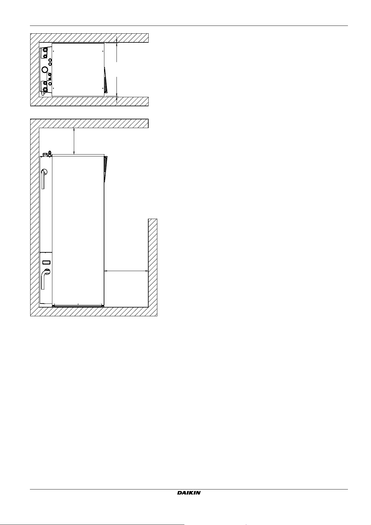
14 Technical data
3D078541
MIN. 500
MIN. 300
MIN. 10 MIN. 10
EHVH/X16
Daikin Altherma - Low Temperature Split
4P313777-1 – 2012.05
Installer reference guide
62
Page 64

14 Technical data
h
f
e
a
c
d
k
b
b
g
y
v
s
l
m
j
r
u
w
x
i
dd
n
p (180 l)
n
q
o
n
t
n
p (260 l)
o
z
z
y
i
x
aa
bb
cc
14.2 Components
14.2.1 Components: Indoor unit
s Backup heater thermal protector
The protector activates when the temperature of the backup
heater becomes too high.
t Drain collector (EHVX models only)
u Drain gutter (EHVX models only)
v Backup heater
Provides additional heating in case of cold outdoor
temperatures. Also serves as backup in case of malfunctioning
of the outdoor unit.
w Manometer
Allows readout of the water pressure in the water circuit.
x Flow sensor
Gives feedback to the interface about the actual flow. Based on
this information (and other), the interface adjusts the pump
speed.
y Air purge valve
Remaining air in the water circuit will be automatically removed
via the air purge valve.
z 3-way valve
Controls whether the water is used for space heating, or the
domestic hot water tank.
aa User interface (accessory)
bb Drain flexible (EHVX models only)
cc Drain flexible pressure relief valve
dd Air valve
NOTICE
The optional equipment is delivered with the EKHTS
domestic hot water tank.
a Space heating cooling out
b Shut-off valves (accessory)
Allows isolation of the indoor unit water circuit side from the
residential water circuit side.
c Domestic hot water out
d Refrigerant liquid connection R410A
e Refrigerant gas connection R410A
f Domestic hot water in
g Fill valve (accessory)
h Space heating cooling in
i Expansion vessel (10 l)
j Pressure relief valve
Prevents excessive water pressure in the water circuit by
opening at 3 bar.
k Water filter
Removes dirt from the water to prevent damage to the pump or
blockage of the heat exchanger.
l Heat exchanger
m Water pump
Circulates the water in the water circuit.
n Thermistors
Determines the water and refrigerant temperature at various
points in the circuit.
o Drain caps
p Tank thermistors (180 l/260 l)
q Domestic hot water tank drain valve
Empties the full tank.
r Switch box
Contains the main electronic and electrical parts of the indoor
unit.
INFORMATION
Some components are not directly accessible when
removing the top plate and/or the front plates. It could be
necessary to remove the isolation of the tank by sliding it
backward of the tank. The components in the switch box
are accessible by removing the switch box cover.
Installer reference guide
63
Daikin Altherma - Low Temperature Split
4P313777-1 – 2012.05
EHVH/X16
Page 65

14.2.2 Components: Switch box (indoor unit)
A7P
A1P
Q1L
X6M X7M
X7MX7M
K1M K2M
K2M
K5M K3M
K2M
F1B F2B
X2M
X1M
X3M
X3M
X4M
X5M
X6Y
X6YA
X6YB
FU1
TR1
a
n
m
l
k
j
ddb
e
e
f
g
h
i
p
q
r
c
e
o
14 Technical data
a Pump PCB A7P (Inverter PCB)
b Backup heater thermal protector Q1L
c Transformer TR1
d Terminals for backup heater X6M/X7M (*9W models only)
e Backup heater contactors K1M, K2M and K5M
f Connectors X6YA/X6YB/X6Y
g Backup heater circuit breaker F1B
h Terminal block X2M (high voltage)
i Terminal block X1M (to outdoor unit)
j Cable tie mountings
k Digital I/O PCB A4P (only for installations with solar kit or digital
I/O PCB kit)
l Demand PCB for power limitation
m Terminal block X5M (low voltage)
n Main PCB A1P
o PCB fuse FU1
EHVH/X16
Daikin Altherma - Low Temperature Split
4P313777-1 – 2012.05
Installer reference guide
64
Page 66

14 Technical data
14.3 Functional diagrams
14.3.1 Functional diagram: Indoor unit
a bihfd g
ec
x
R2TR1T
w
R5T
v
R3T
R4T
u
t s r kn mq jlpo
a Outdoor unit
b Indoor unit
c Expansion vessel
d Manometer
e Air purge valve
f Pressure relief valve
g Backup heater
h Pump
i Flow sensor
j Shut-off valve water outlet (field installation)
k Shut-off valve water inlet with fill valve (field installation)
l Filter
m Heat exchanger (indoor unit)
n Heat exchanger (domestic hot water tank)
o Domestic hot water tank
p Domestic hot water in
q Domestic hot water out
R1T Outlet water heat exchanger thermistor
R2T Outlet water backup heater thermistor
R3T Refrigerant liquid side thermistor
R4T Inlet water thermistor
R5T Tank temperature thermistor
Heating
Cooling
Installer reference guide
65
Daikin Altherma - Low Temperature Split
4P313777-1 – 2012.05
EHVH/X16
Page 67

14.4 Piping diagram
14 Technical data
14.4.1 Piping diagram: Indoor unit
Space heating / cooling
water out
FIELD INSTALLED
shut off valve
with drain/fill
valve
Domestic hot water:
hot water out
Domestic hot water:
cold water in
FIELD INSTALLED
Filter
shut-off valve
with drain/fill
valve
Space heating/
cooling water in
Drain cap
R2T
Domestic Hot Water Tank
Heat exchanger
R5T
BUH
Expansion
vessel
Safety
valve
R1T
Air purge
Manometer
Flow sensor
Pump
Drain cap
R4T
REFRIGERANT SIDE WATER SIDE
Plate heat
exchanger
REFR. OUT
REFR. IN
EVAPORATOR
CONDENSOR
REFR. IN
R3T
REFR. OUT
LEGEND:
CHECK VALVE
FLARE CONN.
SPINNED PIPE
PINCHED PIPE
SCREW CONN.
QUICK COUPLING
FLANGE CONN.
BRAZED CONN.
R5T
R4T
R3T
R2T
R1T
THERMISTOR DESCRIPTION
Tank thermistor
Inlet water thermistor
Refrigerant liquid side thermistor
Outlet water backup heater thermistor
Outlet water heat exchanger thermistor
3D077572
EHVH/X16
Daikin Altherma - Low Temperature Split
4P313777-1 – 2012.05
Installer reference guide
66
Page 68

14 Technical data
X6Y
A4P
A8P
X1M X4M
F2B
F1B
X2M
X5M
Q1L
TR1
K3MK5M
K2MK1M
A1P
A7P
X7MX6M
X4M
X6M, X7M
1
15
X5M
X2M
X1M
4D077028
page 1
T1R (A7P)
M1P
B1L
*
R1H (A3P)
FU1
F1T
E4H
E3H
E2H
*
E1H
R1T (A2P)
R4T
R3T
R2T
R1T
*
PHC1
#M2P
*
F2B
F1B
K5M
TR1
Q1L
K1M, K2M
*
#
#
#
#
*
(*)
*
*
*
X*Y
X*M
SS1 (A4P)
S6S-S9S
S3S
S2S
S1S
R6T
R5T
R2T
R1T (A3P)
Q2L
A7P
#
#
Q1DI, Q2DI
K*R
M3S (*)
M2S
K3M
*
F1U, F2U
*
DS1 (A8P)
*
*
BSK
*
A8P
A4P
*
*
A4P
*
*
*
A3P
A3P
A3P
A2P
A1P
Domestic hot water tank
with solar connection
rectifier bridge (only for *16*)
main supply pump
flow sensor
humidity sensor
fuse T 6.3 A 250 V for PCB
thermal fuse backup heater
booster heater (3 kW)
backup heater element (3 kW)
backup heater element (2 kW)
backup heater element (1 kW)
ambient sensor user interface
inlet water thermistor
refrigerant liquid side thermistor
outlet backup heater thermistor
outlet water heat exchanger thermistor
optocoupler input circuit
domestic hot water pump
overcurrent fuse booster heater
overcurrent fuse backup heater
safety contactor BUH (only *9W)
power supply transformer
thermal protector backup heater
contactor backup heater
# : field supply
connector
terminal strip
selector switch
digital power limitation inputs
electrical meter pulse input 2
electrical meter pulse input 1
preferential kWh rate PS contact
external indoor or outdoor
ambient thermistor
domestic hot water thermistor
external sensor (floor or ambient)
ambient sensor On/OFF thermostat
thermal protector booster heater
6T1 (3~, 230 V, 6 kW)
9WN (3N~, 400 V, 9 kW)
6WN (3N~, 400 V, 6 kW)
6V3 (1N~, 230 V, 6 kW)
3V3 (1N~, 230 V, 3 kW)
Backup heater
configuration
(only for *9W)
Ext. thermistor
Heat pump convector
On/OFF thermostat (wireless)
Add LWT:
On/OFF thermostat (wired)
Heat pump convector
Solar pump and control station
Demand PCB
Digital I/O PCB
Ext. outdoor thermistor
Ext. indoor thermistor
Remote user interface
Ext. thermistor
On/OFF thermostat (wireless)
Main LWT:
On/OFF thermostat (wired)
Domestic hot water tank
(*) : standard for *HV*, optional for *HB*
pump driver PCB (only for *16*)
POSITION IN SWITCH BOX
: Booster heater terminal
: Backup heater terminal
earth leakage circuit breaker
relay on PCB
3 way valve for floorheating/
domestic hot water
2 way valve for cooling mode
contactor booster heater
fuse 5 A 250 V for digital I/O PCB
dipswitch
solar pump station relay
demand PCB
receiver PCB (wireless
On/OFF thermostat)
digital I/O PCB
heat pump convector
On/OFF thermostat (PC=power circuit)
solar pumpstation PCB
user interface PCB
Bottom plate heater
* : optional
NOTES to go through before starting the unit
Translation can be found in the installation manual.
LEGEND
User installed options:
: Wiring depending on model
: Several wiring possibilities
: Connection ** continues on page 12 column 2
: PCB
: Not mounted in switch box: Option
: Field supply
: Wire number 15
: Earth wiring
: Field wiring terminal for DC
: Field wiring terminal for AC
: Main terminal
Part n° Description
main PCB
**/12.2
14.5 Wiring diagram
14.5.1 Wiring diagram – components: Indoor unit
See the internal wiring diagram supplied with the unit (on the inside of
the indoor unit switch box cover). The abbreviations used are listed
below.
Installer reference guide
67
Daikin Altherma - Low Temperature Split
4P313777-1 – 2012.05
EHVH/X16
Page 69

14 Technical data
only for *KHWE*Z2
7
domestic hot water tank domestic hot water tank
E4H E4H E4H
Q2L
X9M
BRNREDGRYBLK BRNREDGRYBLK BRNRED
X6M X7M
K1M
K5M
48765321
E1H
F1T
F1T
21654
21654
1
F1T
3
13
3
14
IIII
8765432
F1T
Q1DI
1N~, 50 Hz
230 V AC
only for *9W
F1T
21654
F1B
X7M
X6M X7M
F1T
3
K2M
F1T
K1M
K5M
Q1DI
1N~, 50 Hz
230 V AC
F1T
21654
21654
1
48765321
F1T
F1T
F1TF1T
IIII
3
21654
13
14
F1B
8765432
3
3
NLNL
K2M
only for *KHWE*V3
2222
BLK
X6M
F1T
K1M
K5M
Q1DI
3~, 50 Hz
230 V AC
domestic hot water tank
Q2L
X9M
GRY
48765321
F1T
3
21654
3
21654
1
for 6T1 (3~, 230 V, 6 kW)for 6WN (3N~, 400 V, 6 kW) and 9WN (3N~, 400 V, 9 kW)for 6V3 (1N~, 230 V, 6 kW)for 3V3 (1N~, 230 V, 3 kW)
IIII
only for *KHWS*Z2
777
3
2
4
1
21
GRY
BLK BRNRED
F1T
21654
21654
1
48765321
3
3
II
X6M X7M
F1T
K2M
K1M
K5M
3
2
Q2L
4
1
21
X6M
E2HE2HE2HE1HE1HE1HE2HE2HE2HE1HE1HE1H
F1T
F1T
F1TF1T
3
21654
13
14
F1B
II
8765432
Q1DI
3N~, 50 Hz
400 V AC
NL2 L3L1 L2 L3L1
only for *KHWS*V3
domestic hot water tank
E4H
2
1
21
F2B
Q2L
X6M
X4M
K3M
2
1
12
214
21
3
31
II
42
Q1DI
E2HE2HE2HE1HE1HE1HE2HE2HE2HE1HE1H
F1T
F1T
F1TF1T
3
K2M
21654
13
14
F1B
8765432
11
1N~, 50 Hz
230 V AC
only for *KHW*V3
11
2~, 50 Hz
400 V AC
only for *KHW*Z2
K1M
Q1L
F2B
NL
L2L1
E3H
F1T
3
214
22
12
21
11
31
II
42
Q1DI
1N~, 50 Hz
NL
230 V AC
only for *3V
Digital I/O PCB
SS1
ON
OFF
KCR KFR
X2M
X2M.13
13a
X2M.14
21
X2M.9
28
29
NL
Ext. heat source
Max. load 0.3 A - 250 V AC
Min. load 20 mA - 5 V DC
Options: boiler output, solar pump connection, alarm output
X2M
X2M.14
21
X2M.9
28
29
Options: bottom plate heater OR On/OFF output
Only for digital I/O PCB option
only for EKBPHT*
F2U
KHR KHUR
Solar pump connection
For *KSOLHWAV1, refer to
operation manual
A4P.YC
A4P.Y2
X2M.29
to bottom
plate heater
X1Y12
OUTDOOR
UNIT
3CN1:1
F1U
Y1 Y2YC Y4Y3X4X3X2X1
Alarm output
Max. load
0.3 A - 250 V AC
Min. load
20 mA - 5 V DC
only for solar pump station
4
Space C/H
On/OFF output
Max. load 0.3 A - 250 V AC
Min. load 20 mA - 5 V DC
only if no EKBPHT*
A4P.Y2
4D077028 page 2
A4P
CN2:1
2
3
4
5
6
PHC1
Switch
box
A3P
21
BSK
Preferential kWh rate
power supply contact:
16 V DC detection
(voltage supplied by
PCB)
S1S
Electric pulse meter
inputs: 5 V DC pulse
detection (voltage
supplied by PCB)
S2S
10
9874 X5M3
S3S
A2P
P2P1
4
R1T
Remote user
interface
-t°
X33A:1
2
3
4
5
6
X40A:1
2
3
4
5
6
7
8
2X18A:1 2X22A:1X85A:1 2 3
Switch
box
X5M21
A2P
P2
P1
R1T
-t°
User interface
X80A:1
2
DS1
ON
OFF
Demand PCB
4
3456789 121110
4321
S6S
S7S
5
S8S
6
S9S
A8P
543 X801M21
Power limitation digital
inputs: 12 V DC / 12 mA
detection
(voltage supplied by PCB)
Only for demand PCB option
A1P
R1T
X5A:1
X6A:1
X7A:1
X8A:1
X9A:1
X4A:1
X5M65
R6T
1
-t°
2
2
2
2
2
2
2
3
4
Switch box
-t°
R2T
-t°
R3T
-t°
R4T
-t°
B1L
ext. ambient
sensor option
(indoor or outdoor)
10
R5T
-t°
only for domestic
hot water option
10
R5T
-t°
only for floor
standing model
EHVH/X16
Daikin Altherma - Low Temperature Split
4P313777-1 – 2012.05
4D077028 page 3
Installer reference guide
68
Page 70

14 Technical data
4D077028 page 4
BLU
BRN
RED
BLK
WHT
KCR
KVR
X2M.8
X2M.7
PE
N
L
GND
PWM
A4P
X2M.28
X2M.14
X2M.1
X2M.2
X2M.3
X2M.2
X2M.4
X2M.1
X2M.4
X2M.1a
X2M.2a
X2M.3
X2M.2a
X2M.4
X2M.1a
X2M.4
X2M.32
X2M.33
X2M.4
X2M.32
X2M.33
X2M.1a
X2M.4
X2M.5
X2M.7
X2M.8
X2M.9
X2M.10
X25A.1
X25A.2
X16A.5
X16A.3
X2M.1
T1R
A7P
9
3
3
5
6543
A3P
X11M
N
L
NC
N
6
65
A3P
X11M
9
8
8
34
NO
3
X3A:1
48
M1P
M1P
MS
3~
2
M2P
M
1~
M3S
M3S
M2S
M2S
13
X9M
14 13
14
10
9X2M567X2M 8
8a
34
X2M
35
3
X2A:4
6
5
4
32X25A:1
1
MS
3~
2
X16A:5
1
3
5
X1A:1
3
A1
A2
K1M
A1
A2
K2M
A1
A2
K3M
X17A:1
3
5
7
X24A:1
3
5
7
1
X1A:3
X19A:1
35
FU1
X26A:1
2
X31A:1 3
3/21/31
4/22/32
Q2L
3
X3A:1
X20A:1
3
5
X2A:1
X21A:1
3
X15A:1
3
E
X14A:1
3
K4R
KPR
FU2
X11A:3
1
X12A:3
1
X13A:3
1
K1R K2R K3RK6R
3
5
X2M.4
X2M.3
X2M.28
X2M.13a
X2M.21
A1P
X2M
3130
1
213
123
X1M
X1M
X6YA
X6Y
X6YB
NL
X1M213
123
X1M
X2M
30 31
COM
H
C
5
A3P
COM
HC
6
A3P
3
4
32
33
2a
1a
2
1
X2M
Q2DI
X6YA
X6Y
X6YB
TR1
R1T
-t°
R1T
-t°
H
COM
CLPCN
5
X1M
A3P
H
COM
CLPCN
6
X1M
A4P
A3P
%H20
R1HR1H
R1T
-t°
R2T
-t°
R1T
-t°
R2T
-t°
%H20
2129
X2M
A1
A2
K5M
31
32
Q1L
11
12
1
only for wireless
On/OFF thermostat
NC valve
Switch
box
Switch box
OUTDOOR
UNIT
OUTDOOR
UNIT
DHW pump output
Max. load:
2 A (inrush) - 230 V AC
1 A (continuous)
Shut-off valve
Only for preferential kWh rate power supply (outdoor)
Use normal kWh rate power supply for indoor unit
Only for normal power supply (standard)
Indoor unit supplied from outdoor
only for floor
standing model
Add LWT zone
Heatpump convector
only for wireless
On/OFF thermostat
only for wired On/OFF thermostat
only for *9W
Main LWT zone
Heatpump convector
only for ext.
sensor
(floor or
ambient)
only for ext.
sensor
(floor or
ambient)
only for wired On/OFF thermostat
only for *04* and *08*
only for *16*
DHW pump
3 wire type
(SPST)
NO valve
only for domestic
hot water option
3 wire type
(SPDT)
domestic hot
water tank
only for
enamel
tank
option
only for
domestic hot
water option
1N~, 50 Hz
230 V AC
Normal kWh rate
power supply
only for domestic hot
water tank option
Installer reference guide
69
Daikin Altherma - Low Temperature Split
4P313777-1 – 2012.05
EHVH/X16
Page 71

14 Technical data
Electrical connection diagram Daikin Altherma
Power supply
Only for normal power supply installation
1
unit power supply: 400 V or 230 V + earth
1
Only for preferential kWh rate power supply installation
unit preferential kWh rate power supply:
400 V or 230 V + earth
normal kWh rate power supply for indoor unit: 230 V
Preferential kWh rate power supply contact
backup heater power supply (3/6/9 kW): 400 V or 230 V + earth
Optional parts (*KHW*)
2
booster heater power supply (3 kW): 230 V + earth
DOMESTIC HOT
WATER TANK
Q*L clixon
Booster heater
Q2L - clixon
booster heater
R5T - thermistor
water temperature
Q*L clixon
3WAY VALVE
M3S (when *KHW is installed)
selection domestic hot water-floor heating
X5M
X6M
X8M
FIELD SUPPLY
Power limitation
demand input 1
Power limitation
demand input 2
Power limitation
demand input 3
Power limitation
demand input 4
2way valve
solar pump
5 or 3 core
5 or 3 core
3 core
2 core
2x0.75
4 or 3 core
3 core
2 core
230 V
5 core
5Gx2.5
230 V
signal
2 core
230 V
230 V
2 core
230 V
2 core
230 V
2 core
230 V
2 core
230 V
Standard parts
OUTDOOR UNIT
X1M: L1-L2-L3-N-earth
or L-N-earth
X1M: 1-2-3
3 core
X1M: 1-2-3
X2M: 30-31
X5M: 3-4
F1B: L1-L2-L3
or L-N + earth
F2B: L-N + earth
X7M
F2B
Only for *KHWSU*V3
X4M: 1-2-earth
X2M: 13-14
X9A (PCB A1P)
A4P: X4
X2M: 28
Only for *KSOLHWAV1
SPST:
X2M: 8-9-10
Only for *KRP1AHTA
A8P: X801M: 1-5
A8P: X801M: 2-5
A8P: X801M: 3-5
A8P: X801M: 4-5
2 core
2x0.75
Bottom plate heater
A4P:Y2
X2M:29
X1Y: 1-2
Only for *KBPHT*
& depending on model
INDOOR UNIT
A4P: Y1
X2M: 28
Alarm output
A4P: Y3
X2M: 29
Solar input
A4P: X1-X2
Changeover to
ext. heat source output
A4P: Y2
X2M: 29
Cooling/heating
On/OFF output
X2M: 34-35
NO valve: X2M: 6-7
NC valve: X2M: 5-7
X5M: 7-8
X5M: 9-10
X5M: 5-6
2
main: X2M: 1-2-4
add: X2M: 1a-2a-4
2
main: X2M: 1-2-3-4
add: X2M: 1a-2a-3-4
2
main: X2M: 1-4
add: X2M: 1a-4
X2M: 32-33
X5M: 1-2
For more details please check unit wiring
Notes:
- In case of signal cable: keep minimum distance to power cables > 5 cm
- Available heaters depending on model: see combination table
FIELD SUPPLY
Only for *KRP1HB* & *KSOLHWAV1
2 core
230 V
2 core
230 V
2 core
signal
2 core
230 V
2 core
230 V
2 core
230 V
2 core
signal
2 core
signal
Only for KRCS01-1 or EKRSCA1
2 core
230 V
EXTERNAL ROOM THERMOSTAT / HEAT PUMP CONVECTOR
(main and/or additional zone)
3 core for C/H operation
2 core for H only operation
230 V
5 core for C/H operation
4 core for H only operation
230 V
4 core
230 V
2 core
2x0.75
communication
communication
alarm indication
Only for *KSR3PA option
BSK: 1-2 solar interlock
Ext. heat source (eg boiler)
Cooling/heating
On/OFF output
Circulation pump
for DHW
2WAY VALVE
M2S (*KHBX units)
for cooling mode
Electricity meter
pulse input 1
Electricity meter
pulse input 2
external thermistor
(indoor or outdoor)
Only for *KRTW
(wired room thermostat)
A3P: X1M: C-com-H
Only for *KRTR
(wireless room thermostat)
A4P: X1M: H-C-com
X2M: L-N
Only for FWXV*
(heat pump convector)
X11M: 3-4-5-6
In case user interface is relocated
A2P: P1-P2 user interface
Only for *KRCAL*
2 core
2x0.75
A2P: P1-P2 user interface
A3P: X1M: 1-3
OPTIONAL PART
2 core
(3m included)
signal
OPTIONAL PART
Only for *KRTETS
R2T
External sensor
(floor or ambient)
EHVH/X16
Daikin Altherma - Low Temperature Split
4P313777-1 – 2012.05
4D078494
Installer reference guide
70
Page 72

14 Technical data
* electrical meter specification
- pulse meter type/voltage free contact for 5 VDC detection by PCB
- possible number of pulse:
0.1 pulse/kWh
1pulse/kWh
10pulse/kWh
100 pulse/kWh
1000 pulse/kWh
- pulse duration:
minimum On time 40ms
minimum OFF time 100ms
- measurement type (depending on installation):
single phase AC meter
three phase AC meter (balanced loads)
three phase AC meter (unbalanced loads)
* electrical meter installation guideline
- General: it is the reponsability of the installer to cover the complete power consumption with electrical meters
(combination of estimation and metering is not allowed)
- Required number of electrical meters:
Outdoor unit type
Indoor unit type
Backup heater type
(#)
Backup heater
power supply
Backup heater
configuration
Electrical
meter type
Electrical
meter type
A1P Main PCB
A2P User interface PCB
A3P * Solar pump station PCB
A3P * On/OFF thermostat (PC=power circuit)
A3P * Heat pump convector
A4P * Digital I/O PCB
A4P * Receiver PCB (Wireless On/OFF
A7P Pump driver PCB (only for EHBH/X04+08
A8P * Demand PCB
B1L Flow sensor
BSK * Solar pump station relay
DS1(A8P) * DIP switch
E1H Backup heater element (1 kW)
E2H Backup heater element (2 kW)
E3H Backup heater element (3 kW)
E4H * Booster heater (3 kW)
F1B Overcurrent fuse backup heater
F2B * Overcurrent fuse booster heater
1~ 1 1 - - 1 1 - - 1 - 1 - -
3~ balanced
3~ unbalanced
1~ 2 1 1 2 1 1 1 - -
3~ balanced
3~ unbalanced
thermostat)
and EHVH/X04+08)
*RLQ(04/06/08)* *R*Q(011/014/016)*V3 *R*Q(011/014/016)*W1
*HB(H/X)(04/08)CA# *HB(H/X)16CA#
3V /
9W 9W 9W
1~
230V
3 / 6
kW
- 1 - - -
- - 1 1 -
- - - - -
- 1 1 - 1
3~
400V 3~230V1~230V
6 / 9
kW
6
kW
*HB(H/X)16CA#
3V /
9W 9W 9W 3V / 9W 9W 9W
3~
400V
3 / 6
kW
Regular kWh rate power supply
Benefit kWh rate power supply
6 / 9
kW
1 - - 1 - 1 - -
- 1 1 - 1 - 1 1
F1T Thermal fuse backup heater
F1U, F2U * Fuse 5 A 250 V for digital I/O PCB
FU1 Fuse T 6.3 A 250 V for PCB
PHC1 * Optocoupler input circuit
K1M, K2M Contactor backup heater
K3M * Contactor booster heater
K5M Safety contactor backup heater (only for
K*R Relay on PCB
M1P Main supply pump
M2P # Domestic hot water pump
M2S # 2-way valve for cooling mode
M3S (*) 3-way valve for floor heating/domestic hot
Q1DI, Q2DI # Earth leakage circuit breaker
Q1L Thermal protector backup heater
Q2L * Thermal protector booster heater
R1T Outlet water heat exchanger thermistor
R1T (A2P) Ambient sensor user interface
R1T (A3P) * Ambient sensor On/OFF thermostat
3~
230V
6
kW
- 1 1 1
1 - 1 1
1~
230V
3 / 6
kW
*9W)
water
3~
400V
6 / 9
kW
3~
230V
kW
4D078288
6
Installer reference guide
71
Daikin Altherma - Low Temperature Split
4P313777-1 – 2012.05
EHVH/X16
Page 73

14 Technical data
15
**
/12.2
1
R2T Outlet backup heater thermistor
R2T * External sensor (floor or ambient)
R3T Refrigerant liquid side thermistor
R4T Inlet water thermistor
R5T (*) Domestic hot water thermistor
R6T * External indoor or outdoor ambient
thermistor
R1H (A3P) * Humidity sensor
S1S # Preferential kWh rate power supply contact
S2S # Electrical meter pulse input 1
S3S # Electrical meter pulse input 2
S6S~S9S # Digital power limitation inputs
SS1 (A4P) * Selector switch
T1R (A7P) Rectifier bridge (only for EHBH/X04+08 and
EHVH/X04+08)
TR1 Power supply transformer
X*M Terminal strip
X*Y Connector
* = Optional
(*) = Standard for EHVH/X, optional for EHBH/X
# = Field supply
BLK Black
BRN Brown
GRY Grey
RED Red
English Translation
On/OFF thermostat (wireless) On/OFF thermostat (wireless)
Ext. thermistor Extended thermistor
Heat pump convector Heat pump convector
Add LWT Additional leaving water
temperature
Notes to go through before starting the unit
English Translation
X1M Main terminal
X2M Field wiring terminal for AC
X5M Field wiring terminal for DC
X6M, X7M Backup heater terminal
X4M Booster heater terminal
Earth wiring
Wire number 15
Field supply
Connection ** continues on page
12 column 2
Several wiring possibilities
Option
Not mounted in switch box
Wiring depending on model
PCB
Backup heater configuration
(only for *9W)
User installed options User installed options
Bottom plate heater Bottom plate heater
Domestic hot water tank Domestic hot water tank
Domestic hot water tank with
solar connection
Remote user interface Remote user interface
Ext. indoor thermistor Extended indoor thermistor
Ext outdoor thermistor Extended outdoor thermistor
Digital I/O PCB Digital I/O PCB
Demand PCB Demand PCB
Solar pump and control station Solar pump and control station
Main LWT Main leaving water temperature
On/OFF thermostat (wired) On/OFF thermostat (wired)
Backup heater configuration
(only for *9W)
Domestic hot water tank with
solar connection
EHVH/X16
Daikin Altherma - Low Temperature Split
4P313777-1 – 2012.05
Installer reference guide
72
Page 74

14 Technical data
*RLQ004*V3
*RLQ004*V3
*RLQ006*V3
*RLQ008*V3
*RLQ006*V3
*RLQ008*V3
*RLQ006*V3
*RLQ008*V3
*RLQ006*V3
*RLQ008*V3
*R(H/L)Q011*V3
*R(H/L)Q011*W1
*R(H/L)Q014*V3
*R(H/L)Q014*W1
*R(H/L)Q016*V3
*R(H/L)Q016*W1
*R(H/L)Q011*V3
*R(H/L)Q011*W1
*R(H/L)Q014*V3
*R(H/L)Q014*W1
*R(H/L)Q016*V3
*R(H/L)Q016*W1
*R(H/L)Q011*V3
*R(H/L)Q011*W1
*R(H/L)Q014*V3
*R(H/L)Q014*W1
*R(H/L)Q016*V3
*R(H/L)Q016*W1
*R(H/L)Q011*V3
*R(H/L)Q011*W1
*R(H/L)Q014*V3
*R(H/L)Q014*W1
*R(H/L)Q016*V3
*R(H/L)Q016*W1
*HVX08S18CA3V *HVH04S18CA3V *HVH08S26CA9W*HVH08S18CA3V*HVX04S18CA3V *HVH16S26CA9W *HVX16S26CA9W *HVX16S18CA3V*HVH16S18CA3V
*HVX08S26CA9W
kPa
kPa
kPa
kPa
kPa
kPa
kPa
kPa
46 46 46 46 46 46 46 46 46 46
190
690
818
600
728
142
142 134 133 140 139 130 129 128 128
129 129 121 120 126 126 117 116 115 115
36 35 56
62
86 93
36
35
56
62
86 93
36
35 56 62 86 93
36
35 56 62 86 93
23 23
44
51
82
84 23 23 44 51
82
84
23
23 44
51
82 84
23 23
44
51 82 84
12 -4 23 3 37
52
- 12 -4 23 3 37 52
-
62
62
69 69 78
95 - 62 62 69 69
78
95
-
- - -
160160 160160160160 160160160160160
160
160160
160
160160 160 160 160 160 160 160 160
41 51 41 51 41 51 41 51 55
37 49 37
49
37 49 37
49
52
41 42 - 41 42 - 45 -
54 57 -
54
57
- 54 -
W
/
/
/
12
Ps*DN
Ps*V
50
34 34 25
-
50 - 34
-
34 - 25 -
- - - -
-
- - -
##
##
-
-
- -
- - -
11
11 5
25 ~ 60 25 ~60
2
5~60
1
5~55 15~55
1
5~55
-5~22
-
5~
22 - 5
~22
-25 ~ 35 -25 ~ 35 -25 ~ 35
-25 ~ 25 -25~25 -25~25
-10 ~ 43 - 10~43 - 10~43
28
42
28
42
28
42
25 ~60 25 ~60
15 ~ 55 15 ~ 55
-
5~
22 -
5~22
-20 ~ 35 -20~ 35
-10~46-10~46
-25 ~ 35 (12) -25 ~ 35 (12)
33 33
47 47
260 180 260 180
50
50
10
65
1
1
3
10
818
690
75
728
600
W
/
/
/
1
-
-
-
-
3
1
dBA
dBA
°C
°C
°C
°C
°C
°C
°C
kWh/2
//
12
1922
1732
1922
1732
EPS EPS
EPS
EPS
3
1
-
-
1
1
1
3
10
1
11
3D077571_A page 1
Copper - brass - stainless steel
Stainless steel (EN 1.4521)
TECHNICAL SPECIFICATIONS
l 4,4 4,8 5,8 4,5 5,5
1,4 1,4 1,9 1,4
1,4
1,91,41,4 1,9 1,9
65
l
0,9 1,3
1,3
cat. l cat. l A3§rt3*
HEATING
ONLY TYPE
REVERSIBLE
TYPE
HEATING
ONLY TYPE
REVERSIBLE
TYPE
HEATING
ONLY TYPE
REVERSIBLE
TYPE
HEATING ONLY TYPE REVERSIBLE TYPE HEATING ONLY TYPE REVERSIBLE TYPE
l/min
l/min
l/min
l/min
l/min
l/min
l/min
l/min
l/min
l/min
l/min
Pre-coated sheetmetal
White
Wood - carton - PE wrapping foil
34,6 55,9 85,8 34,6 55,9 85,8 34,6
55,9
85,8 34,6 55,9 85,8
23,1 44,1 83,6 23,1
44,1
83,6 23,1 44,1 83,6 23,1 44,1
83,6
12,1 22,5 37,0 12,1 22,5 37,0
61,9 68,6 78,0
61,9
68,6
78,0
Wood - carton - PE wrapping foil
Machine net weight
Unit
Depth
Height
Width
Depth
Width
Height
Dimensions
Material
Colour
Casing
Nominal input (Indoor only)
Outdoor units
category of unit
Material
Packing
materials
Weight
most critical part =
PED
Weight of unit
Weight of unit
Packing
Packed machine weight
Main
components
hydrobox
Main
components
tank
Tank
Heat exchanger
3 way valve
Water circuit -
space heating /
cooling side
Safety devices
* excluded from scope of PED due to article 1, item 3.6 of 97/23/EC
Pump
Water side Heat
exchanger
Water Filter
Expansion vessel
Total Water Volume (6)
Air purge valve
Shut off valves
Drain valve / Fill valve
Manometer
Safety valve
Piping connections ø (7)
Cooling (2)
Cooling (8)
Heating (3)
Heating (13)
Cooling (2)
Cooling (8)
Heating (3)
Heating (13)
Cooling (2)
Cooling (8)
Heating (3)
Heating (13)
Cooling (2)
Cooling (8)
Heating (3)
Cooling
Heating
Heating (13)
bar*l
bar
kg
kg
kg
Type
nr. of speed
nominal ESP unit
(*RLQ*C*)
nominal ESP unit
(*RH/LQ*B*)
Water flow rate Min. (11)
Water volume
Water flow rate Nom.
(*RH/LQ*B*)
Water flow rate Nom.
(*RH/LQ*B*)
Water flow rate Max.
qty
Type
Power input
Material
Diameter perforations
Pre pressure
Max. water pressure
Volume
Insulation material
Pre-coated sheetmetal
White
mm
mm
mm
mm
mm
mm
A3§rt3*
Inverter controlled
DC motor
Plate heat exchanger Plate heat exchanger
51,0 51,0
43,6
39,0
31,5
43,6
39,0 31,5 43,6 39,0 31,5
43,6
39,0 31,5 19,8 16,3
19,8
16,3 19,8
16,3
19,8
16,3
11,6
45,9
41,6
32,1 45,9 41,6 32,1 45,9 41,6 32,1 45,9 41,6 32,1
21,2
17,2 21,2 17,2 21,2 17,2 21,2 17,2 12,6
48,0
46,0
43,1
48,0
46,0 43,1
- 19,7 19,4 19,7 19,4 14,3
37,6
36,0
33,6 37,6 36,0 33,6 - 15,4 13,9 15,4 13,9 12,0
43,343,638,937,631,529,5
43,3
43,637,6
31,5
29,5
##
43,6
38,937,6
31,529,543,3 43,6 38,9 37,6
31,5
29,5
46,045,941,640,1
32,5
32,146,0
45,940,1
32,5
32,1
## 45,9
41,6
40,1
32,5
32,1
46,0 45,9
41,6
40,1
32,5
32,1
48,051,0
46,049,6
43,139,8
##
51,0
46,049,6
43,139,8
37,6
37,636,0
35,8
33,6
28,7
## 37,636,0
35,8
33,628,7
1,0
(1) Heatloss according to EN12897
(2) Tamb 35°C - LWE 7°C ( DT=5°C )
(3) DB/WB 7°C/6°C - LWC 35°C ( DT=5°C)
(4) The sound pressure level is measured via a microphone at 1m from the unit. It is a relative value, depending on the distance and acoustic environment.
The sound pressure level mentioned is valid for pump medium speed - 0 ESP / medium speed - nominal flow / high speed - nominal flow
(5) 15°C ~ 25°C: BUH only, no Heatpump operation = during commissioning
(6) Including piping + PHE + backup heater / excluding expansion vessel
(7) Value mentioned is connection after ball valves. Is same as connection at unit (G1-1/4 FEMALE).
(8) Tamb 35°C, LWE 18°C (DT = 5°C)
(9) details, see operation range drawing
(10) For *RLQ* outdoor units: >55°C BUH only, no heatpump operation
For *RHQ* outdoor units: > 50°C BUH only, no heatpump operation
(11) Minimum flow is mentioned for heat pump operation. To allow backup heater to operate safely, a higher minimum flow is required:
For *3V models: 12 l/min
For *9W models: 15 l/min
(12) Refer to operation range detail for diferences between *RHQ* and *RLQ* models
(13) DB/WB 7°C/6°C - LWC 45°C (DT = 5°C)
Refrigerant
circuit
Notes:
Operation
range (9)
Sound level
Water circuit domestic hot
water side
10
Stainless steel ( EN 1.4521 )
Copper - brass - stainless steel
l
bar
mm
bar
l
Thermal cut out
Kvs space heating / tank heating
Internal coil volume
Surface
Material
Quantity
Heatlosses (1)
Corrosion protection
Insulation material
Maximum pressure
Maximum temperature
Material
Water volume
Piping connections recirculation connection
Piping connections - cold water in / hot water out ø
Waterside
Ambient
Sound pressure (4)
Sound power (3)
Liquid side ø
Gas side ø
DHW(10)
Space heating (5)
Space cooling
DHW
Space heating
Space cooling
nominal flow
nominal flow
heating
heating
mm
mm
inch
inch
6,35
6,35
6,35
15,9 15,9
15,9
G 1/2" FEMALE
G 1" FEMALE
9,52 9,52
15,9 15,9
G 1/2" FEMALE
G 1" FEMALE
Yes Yes
Yes Yes
Yes Yes
Yes Yes
bar
G 1-1/4 (FEMALE) G 1-1/4 (FEMALE)
inch
13/8
13/8
m³/h
8,9 8,9 l
1,9 1,9 m²
Stainless steel ( EN 1.4521 )
Stainless steel (EN 1.4521)
Anode Anode
bar
Brazed plate
Brazed plate
Inverter controlled
DC motor
14.6 Technical specifications
14.6.1 Technical specifications: Indoor unit
Installer reference guide
73
Daikin Altherma - Low Temperature Split
4P313777-1 – 2012.05
EHVH/X16
Page 75

14 Technical data
3G
4
2
2
2
2
3
3G
4
G3G3G4G/5G4G/5G
V 253 253 253 253 440 440
V 207 207 207 207 360 360
A 13
230 230 400 400230
50
5
0
3~3~3~1~ 1~ 1~
3V 9W
kVA - - - (9) - -
- - - - -
A 13
3 6 3 6 6 9
2
V
Hz
kW
Ω
13
3D077571_A page 2
26
1313
13 26
ELECTRICAL SPECIFICATIONS
Note (3) and (5)
Note (3) and (5)
Note (6)
Note (3)
Note (3) Note (3) Note (3) Note (3) Note (3) Note (3)
Voltage
Frequency
Phase
Capacity setting
(1) Above mentioned power supply of the hydro box is for the backup heater only. The Switch box & pump of the hydrobox are supplied via the outdoor unit.
(3) Select diameter and type according to national and local regulations
(4) For more details of the voltage range and current refer to installation manual
(5) Voltage: 230V / Maximum current: 100mA / Minimum 0,75mm²
(6) Depends on thermostat type, refer to installation manual
(7) Wire included in option *KHW*
(8) In accordance with EN/IEC 61000-3-11(*), it may be necessary to consult the distribution network operator to ensure that the equipment is connected only to a supply with Zsys(***) ≤ Zmax
(9) Equipment complying with EN/IEC 61000-3-12 (**)
(*) : European/International Technical Standard setting the limits for voltage changes, voltage fluctuations and flicker in public low-voltage supply systems for equipment with rated current ≤ 75A.
(**) : European/International Technical Standard setting the limits for harmonic currents produced by equipment connected to public low-voltage systems with input current >16A and ≤ 75A per phase.
(***) : System impedance
Notes
bfor connection with
bottom plate heater
100 mA, minimum 0,75 mm²
type of wires
for connection with
optional FWXV*
(demand input and
output signal)
for connection with
M2S
for connection with
A3P
Minimum 0,75 mm²
for connection with
R6T
Minimum 0,75 mm² (2A inrush, 1A continuous)
domestic hot
water pump
Minimum 0,75 mm² (5VDC pulse detection)
Electricity meter
signal : 0,75 mm² till 1,25 mm²(max length 50 m)
power : 6,3 A note (3)
signal : 2
power : 2
Preferential kWh
rate power
supply
0,75 mm² till 1,25 mm² (max length 500 m)
User interface
2,5 mm²
Communication
cable
power supply for
back up heater
connections
Wiring
Maximum
Voltage range
(4)
Running Current
backup heater
Minimum S
sc
value (8)
Zmax (back-up heater)
Current
Power supply (1)
Type
Electric heater
( optional )
type of wires
type of wires
quantity of wires
quantity of wires
type of wires
quantity of wires
type of wires
quantity of wires
type of wires
quantity of wires
type of wires
quantity of wires
type of wires
quantity of wires
quantity of wires
type of wires
quantity of wires
type of wires
quantity of wires
type of wires
quantity of wires
Running Current (back-up heater)
0,29
15,1
8,7
15,1 8,7
Minimum
EHVH/X16
Daikin Altherma - Low Temperature Split
4P313777-1 – 2012.05
Installer reference guide
74
Page 76
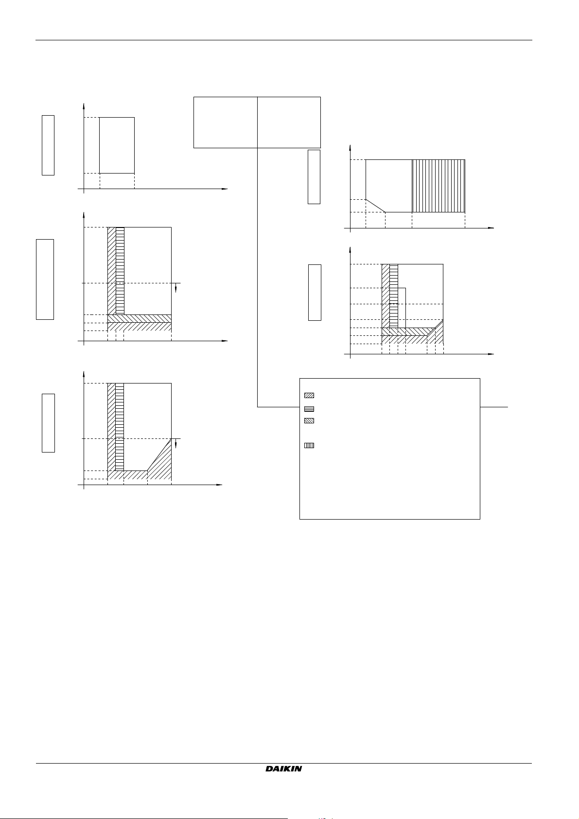
14 Technical data
14.7 Operation range
14.7.1 Operation range: Indoor unit
outdoor temp. (°CDB)
46
1 PHASE + 3 PHASE
11~16kW - CLASS
10
522
outdoor temp. (°CDB)
35
0
3 PHASE B-SERIES
11~16kW - CLASS
1 PHASE + 3 PHASE C-SERIES
–20
–25
15 18 25 55
outdoor temp. (°CDB)
35
1 PHASE B-SERIES
0
11~16kW - CLASS
HEATING MODE HEATING MODE COOLING MODE
–20
15 18 25 5540
INDOOR:
AA-SERIES
AB-SERIES
BA-SERIES
BB-SERIES
CA-SERIES
leaving evaporator
water temperature (°C)
(
)
*
leaving condensor
water temperature (°C)
(
)
*
leaving condensor
water temperature (°C)
INDOOR:
CA-SERIES
REMARK: FOR RESTRICTED POWER SUPPLY CONDITION MODE
OUTDOOR UNIT, BOOSTER HEATER AND BACKUP HEATER
CAN ONLY OPERATE SEPERATELY.
(*)
outdoor temp. (°CDB)
46
1 PHASE C-SERIES
4~8kW - CLASS
18
10
513 22 50
outdoor temp. (°CDB)
25
10
0
1 PHASE C-SERIES
4~8kW - CLASS
HEATING MODE COOLING MODE
–15
–20
–25
15 18 25 30 5550
LEGEND:
ONLY BACKUP HEATER OPERATION
:
(NO OUTDOOR UNIT OPERATION)
OUTDOOR UNIT OPERATION IF SETPOINT ≥25°C
:
OPERATION OF OUTDOOR UNIT POSSIBLE, BUT NO
:
GUARANTEE OF CAPACITY.
(IF OUTDOOR TEMPERATURE < –20°C or < –25°C OUTDOOR UNIT WILL STOP)
(INDOOR UNIT AND BACKUP HEATER OPERATION WILL CONTINUE)
PULL DOWN AREA
:
*RLQ units include special equipment (insulation, heater sheet, ...)
to ensure good operation in areas where low ambient temperature
can occur together with high humidity conditions. In such
conditions the *RHQ models may experience problems with severe
ice build up on the aircooled coil.
In case such conditions ara expected, the *RLQ must be
installed instead. These models contain countermeasures
(insulation, heater sheet, ...) to prevent freeze up.
leaving evaporator
water temperature (°C)
45
leaving evaporator
water temperature (°C)
3TW60813-1A
Installer reference guide
75
Daikin Altherma - Low Temperature Split
4P313777-1 – 2012.05
EHVH/X16
Page 77
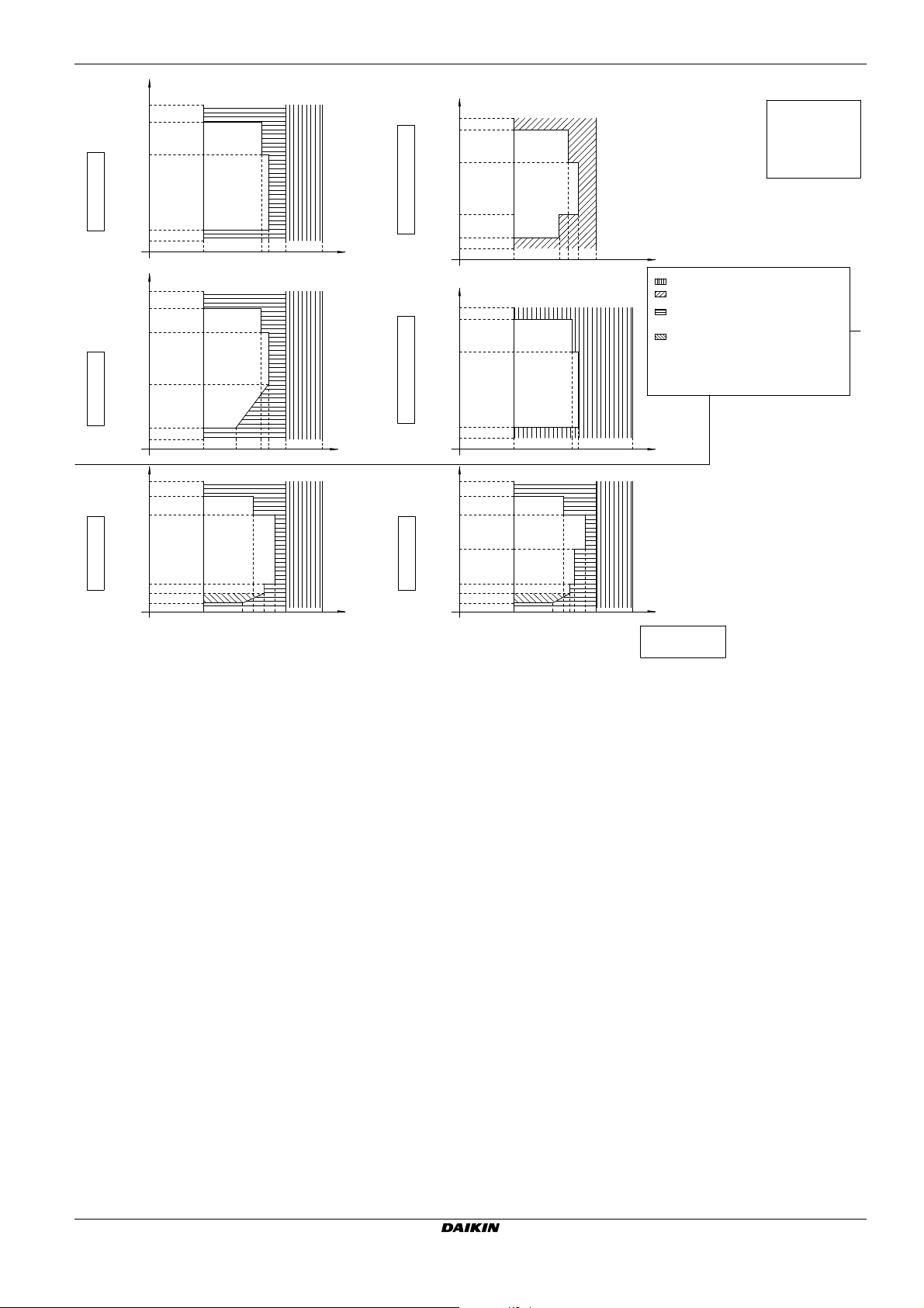
outdoor temp. (°CDB)
35
25
outdoor temp. (°CDB)
35
25
14 Technical data
INDOOR UNITS:
BB-SERIES
CA-SERIES
3 PHASE B-SERIES
11~16kW - CLASS
–20
DOMESTIC WATER HEATING MODEDOMESTIC WATER HEATING MODEDOMESTIC WATER HEATING MODE
outdoor temp. (°CDB)
35
25
0
1 PHASE B-SERIES
11~16kW - CLASS
–20
outdoor temp. (°CDB)
35
25
1 PHASE C-SERIES
4kW - CLASS
–15
–20
–25
25 48 6050 80
25 35 48 6050 80
25 40 45 55 6050 80
domestic hot water
tank temperature (°C)
domestic hot water
tank temperature (°C)
domestic hot water
tank temperature (°C)
–10
1 PHASE + 3 PHASE C-SERIES
11~16kW - CLASS
DOMESTIC WATER HEATING MODEDOMESTIC WATER HEATING MODEDOMESTIC WATER HEATING MODE
–20
25 5553 6050
outdoor temp. (°CDB)
35
25
1 PHASE + 3 PHASE C-SERIES
11~16kW - CLASS
–20
25 48 8050
outdoor temp. (°CDB)
35
25
5
1 PHASE C-SERIES
6~8kW - CLASS
–15
–20
–25
25 5540 45 60 8050
domestic hot water
tank temperature (°C)
LEGEND:
:
ONLY BOOSTER HEATER OPERATION (EKHW* ONLY)
ONLY BACKUP HEATER OPERATION (EKHV*BB + EKHTS*,
:
EHV*CA* ONLY)
:
ONLY BOOSTER HEATER OPERATION (EKHW* ONLY)
ONLY BACKUP HEATER OPERATION (EKHV*BB + EKHTS*,
EHV*CA* ONLY)
OPERATION OF OUTDOOR UNIT POSSIBLE, BUT NO
:
GUARANTEE OF CAPACITY.
(IF OUTDOOR TEMPERATURE < –25°C OUTDOOR UNIT WILL STOP)
(INDOOR UNIT AND BOOSTER/BACKUP HEATER OPERATION
WILL CONTINUE)
REMARK: FOR RESTRICTED POWER SUPPLY CONDITION MODE
(EKHW* ONLY) OUTDOOR UNIT, BOOSTER HEATER
AND BACKUP HEATER CAN ONLY OPERATE SEPARATELY.
domestic hot water
tank temperature (°C)
domestic hot water
tank temperature (°C)
48
INDOOR UNITS:
CA-SERIES
3TW60813-2B
EHVH/X16
Daikin Altherma - Low Temperature Split
4P313777-1 – 2012.05
Installer reference guide
76
Page 78
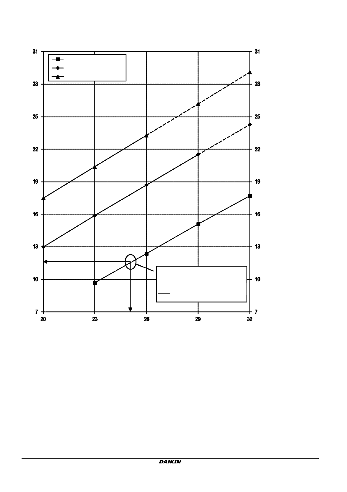
14 Technical data
4D078990
1. Refer to psychometric chart for more information.
2. If condensation is expected, installation of EKHBDPCA2 - drainpan kit must be considered.
Entering water temperature limit to prevent condensation
Entering water temperature [°C]
Entering water temperature [°C]
Dry bulb temperature [°C]
Relative humidity 40%
Relative humidity 60%
Relative humidity 80%
Example:
With ambient temperature of 25°C
and relative humidity of 40%.
If entering water temperature is
below 12°C, condensation on water
piping will happen.
Installer reference guide
77
Daikin Altherma - Low Temperature Split
4P313777-1 – 2012.05
EHVH/X16
Page 79

14.8 ESP curve
0 1020304050
0
40
20
60
100
80
120
140
ESP [kPa]
EHV(H/X)16*CA3V 12
EHV(H/X)16*CA9W 15
4D078833
Minimum flow required during backup heater operation
Unit Flow
Water flow rate: Waterflow through
space heating - cooling circuit
See dashed lines
ESP: External Static Pressure Available
at space heating-cooling circuit
Area of
operation
Water flow rate [l/min]
Notes:
1) Selecting a flow outside the area of operation can cause damage or malfunctioning of the unit.
See also minimum and maximum allowed waterflow range in the technical specifications.
2) Water quality must be according to EN directive EC 98/83 EC.
14.8.1 ESP curve: Indoor unit
14 Technical data
EHVH/X16
Daikin Altherma - Low Temperature Split
4P313777-1 – 2012.05
Installer reference guide
78
Page 80

14 Technical data
4D079038 page 1
EHV*04S18CA
EHV*08S18CA
EHV*08S26CA
EKHWS*150*
EKHWS*200*
EKHWS*300*
ERLQ004CA* &
EHB*04CA*
ERLQ00(6/8)CA* &
EHB*08CA*
73
N/A
N/A
N/A
55
77
81
84
122
736899
ERLQ004CA* & EHV*04S18CA*
ERLQ004CA* & EHB*04CA* & EKHWS*300*
ERLQ004CA* & EHB*04CA* & EKHWS*200*
ERLQ004CA* & EHB*04CA* & EKHWS*150*
ERLQ00(6/8)CA* & EHV*08S18CA*
ERLQ00(6/8)CA* & EHB*08CA* & EKHWS*150*
ERLQ00(6/8)CA* & EHB*08CA* & EKHWS*200*
ERLQ00(6/8)CA* & EHV*08S26CA*
ERLQ00(6/8)CA* & EHB*08CA* & EKHWS*300*
130
120
110
100
90
80
70
60
50
40
130
120
110
100
90
80
70
60
50
40
ERLQ00(6/8)CA*
ERLQ004CA*
40 45 50
40 45 50 40 45 50
160
140
120
100
80
60
40
Heat up times GBS (1) :
Notes:
(1) Time required to heat up the tank starting from a temp of 10°C up to the indicated temp with the heatpump only.
Refer to operation range for maximum tank temperature with heatpump only.
Tank temperature (°C) Tank temperature (°C)
Tank temperature (°C)
Heat-up time (min)
Heat-up time (min)
Heat-up time (min)
Heat-up time tank until 45°C
14.9 Performance
Installer reference guide
79
Daikin Altherma - Low Temperature Split
4P313777-1 – 2012.05
EHVH/X16
Page 81

ERHQ011B* & EHV*16S18CA*
ERHQ014B* & EHV*16S18CA*
ERHQ016B* & EHV*16S18CA*
ERHQ011B* & EHB*16CA* & EKHWS*200*
ERHQ014B* & EHB*16CA* & EKHWS*200*
ERHQ016B* & EHB*16CA* & EKHWS*200*
ERLQ011C* & EHV*16S18CA*
ERLQ014C* & EHV*16S18CA*
ERLQ016C* & EHV*16S18CA*
ERLQ011C* & EHB*16CA* & EKHWS*200*
ERLQ014C* & EHB*16CA* & EKHWS*200*
ERLQ016C* & EHB*16CA* & EKHWS*200*
EHV*16S18CA
EHV*16S26CA
38
52
695580
EKHWS*150*
EKHWS*200*
EKHWS*300*
ERLQ016C* &
EHB*16CA*
40 45 50 40 45 50
40 45 50 40 45 50
140
130
120
110
100
90
80
70
60
50
40
100
90
80
70
60
50
40
30
100
90
80
70
60
50
40
30
140
130
120
110
100
90
80
70
60
50
40
4D079038 page 2
Heat up times GQI (1) :
Tank temperature (°C)
Heat-up time tank until 45°C
Notes:
(1) Time required to heat up the tank starting from a temp of 10°C up to the indicated temp with the heatpump only.
Refer to operation range for maximum tank temperature with heatpump only.
Tank temperature (°C)
Tank temperature (°C) Tank temperature (°C)
Heat-up time (min)
Heat-up time (min)
Heat-up time (min)
Heat-up time (min)
14 Technical data
EHVH/X16
Daikin Altherma - Low Temperature Split
4P313777-1 – 2012.05
Installer reference guide
80
Page 82

14 Technical data
4D079038 page 3
450
400
350
300
250
200
150
Veq 40°C [l]
1,55
1,77
2,19
1,38
1,91
150l
200l
300l
EKHWS*
EHV*
180l
260l
40 42 44
46 48 50 52 54 56 58 60
EHV*S18CA*
EHV*S26CA*
Medium tapping pattern EN16147 (= 2 persons)
Large tapping pattern EN16147 (= 3~4 persons)
Heat loss of domestic hot water tank (4)
Selection guidance of domestic hot water tank volume (3)
Tank temperature (°C)
Heat loss [kWh/24h]
Notes:
(2) Time required to heat up the tank starting from a temp of 10°C up to the indicated temp with the heatpump only.
(3) According to EN16147
(4) According to EN12897
If a higher daily Veq 40°C is required then additional heat up cycles are required within 24 hours. Refer to the operation manual for more information.
Tank
Heat loss [kWh/24h]
Ta nk
Veq 40°C = amount of water that can be tapped with a temperature of 40°C when the hot water tank is heated till a certain temperature with a cold water inlet temperature of 10°C.
The 40°C is considered as a comfrotable domestic hot water temperature.
Installer reference guide
81
Daikin Altherma - Low Temperature Split
4P313777-1 – 2012.05
EHVH/X16
Page 83

14.10 Combination table
oooo
oooo
oooo
oooo
oooo
oooo
oooo
oooo
o o (5) o o (5)
o o (5) o o (5)
o o (5) o o (5)
oooo
--- ---o
---
*RLQ006CA*V3* *RLQ008CA*V3* *RHQ011B*(V3/W1)
*RHQ011B*(V3/W1) *RHQ014B*(V3/W1) *RHQ016B*(V3/W1) *RLQ011C*(V3/W1)
o---------
*RLQ004CA*V3* *RLQ006CA*V3* *RLQ008CA*V3*
--- o o ---
--- o o --- ---
--- --- ---
o --- --- --- ---
--- ---
--- --- --- o o
--- --- o o
*RLQ016C*(V3/W1)
---
---
---
---
oo
ooo
--- ---
--- ---
*RLQ014C*(V3/W1)
---
---
---
---
oo
---
*RHQ014B*(V3/W1) *RHQ016B*(V3/W1) *RLQ011C*(V3/W1)
oo---
oo
o
o
o --- (8)
--- --- ---
--- ---
# - ##
o
o
o
--- (8)
---
---
*RLQ014C*(V3/W1) *RLQ016C*(V3/W1)
---
---
--- (8)
*RLQ004CA*V3*
--- --- ---
--- --- ---
--- --- ---
oo
oooo
--oo
--oo
--oo
--oo
oo- -
--oo
3D078227-1
oooo
18 - 3V 26 - 9W
18 - 3V 26 - 9W
18 - 3V
18 - 3V
oo
--
--
--
--
oo
--
04 # - ##
18 - 3V
26 - 9W
(9)
18 - 3V
# - ##
26 - 9W
(9)
Description Description
Heating only model *HVH* Heating only model *HVH*
Reversible model *HVX* Reversible model *HVX*
Back up heater 3kW 1N~230 V Back up heater 3kW 1N~230 V
Back up heater 6kW 1N~230 V Back up heater 6kW 1N~230 V
Back up heater 6kW 3N~400 V Back up heater 6kW 3N~400 V
Back up heater 6kW 3~230 V Back up heater 6kW 3~230 V
Back up heater 9kW 3N~400 V Back up heater 9kW 3N~400 V
Domestic hot water tank 180L Domestic hot water tank 180L
Domestic hot water tank 260L Domestic hot water tank 260L
Outdoor combination table for *HV(H/X)(04/08)S(18/26)CA* and *HB(H/X)16S(18/26)CA*
*HVH04S18CA* Heating only indoor unit
*HVX04S18CA* Reversible indoor unit
*HVH08S(18/26)CA* Heating only indoor unit
*HVX08S(18/26)CA* Reversible indoor unit
*HVH16S(18/26)CA* Heating only indoor unit
*HVX16S(18/26)CA* Reversible indoor unit
Kit availability for outdoor units
EKDP008CA Drain pan kit
*KDK04 Drain plug kit (3)
*KBPHTH16A Bottom plate heater (1) (3) (10)
*K016SNC Snow cover
Kit availability
Reference Description
Heating only model *HVH*
Reversible model *HVX*
*KRSCA1 Remote sensor for outdoor (11)
KRCS01-1 Remote sensor for indoor (11)
*KRUCAL1 User interface language group 1
*KRUCAL2
User interface language group 2
*KRP1HBAA
Digital I/O PCB (2)
*KRP1AHTA Demand PCB (6)
*KRTWA Wired room thermostat option kit
*KRTR1 Wireless room thermostat option kit (incl. receiver)
*KRTETS external temperature sensor option kit (4)
FWXV15AVEB Heat pump convector
FWXV20AVEB Heat pump convector
*KVKHPC Valve kit heat pump convector (5)
*KPCCAB1 PC cable kit (12)
AvailabilityTBC
Remark: Other combinations than mentioned in this combination table are prohibited
(1) Heater tape that can be fixed on the bottom plate to prevent excessive ice formation.
(2) PCB that provides additional output connections:
(a) Control external heat source (bivalent operation)
(b) Output remote ON/OFF signal Space heating/cooling OR bottom plate heater *KBPHTH16* control
(c) Remote alarm output
(3) It is not allowed to combine bottom plate heater and drain plug/stop kit
(4) *KRTETS can only be used in combination with *KRTR1
(5) Valve kit mandatory if heat pump convector is installed on reversible model (not mandatory for heating only model)
(6) PCB to receive up to 4 digital inputs for power limitation, only for *HB(H/X)04/08CA
(8) Bottom plate heater is factory mounted and controlled by outdoor unit.
(9) Unified model, the actual BUH capacity depends on the actual internal upwiring
(10) Requires digital I/O PCB *KRP1HBAA
(11) Only 1 remote sensor can be connected : indoor OR outdoor sensor
(12) Data cable for connection with PC
Factory mounted optional equipment for *HV(H/X)08S#CA## and
*HV(H/X)16S#CA##
Factory mounted optional equipment for
*HV(H/X)04S#CA##
AvailabilityTBC
14 Technical data
EHVH/X16
Daikin Altherma - Low Temperature Split
4P313777-1 – 2012.05
Installer reference guide
82
Page 84

4P313777-1 2012.05
Copyright 2012 Daikin
 Loading...