How it Works
Log In / Sign Up
Buy Points
How it Works
FAQ
Contact Us
Questions and Suggestions
Users
Daikin
Loading...
E
EKVSU180A
EKVSU260A
EKWCTRAN1V3
26
EKWCTRDI1V3
52
EKWCVATR1V3
25
EKWHCTRL0
23
EKWHCTRL1
25
EKWUFHTA1V3
26
EMRQ10A
EMRQ10AAY1
EMRQ10ABY1
20
EMRQ12A
EMRQ12AAY1
EMRQ12ABY1
20
EMRQ14A
EMRQ14AAY1
EMRQ14ABY1
20
EMRQ16A
EMRQ16AAY1
EMRQ16ABY1
20
EMRQ8A
EMRQ8AAY1
EMRQ8ABY1
20
EMRQ-A
ENVi
2
EPCC
EPGA11DAV3
86
EPGA14DAV3
85
EPGA16DAV3
86
EP HT 3H
EPIA6
3
EPIMSA6
3
EPRA14DAV3
225
EPRA14DAW1
225
EPRA16DAV3
225
EPRA16DAW1
225
EPRA18DAV3
225
EPRA18DAW1
225
EQUICKFIXA
ER10DAT1
ER10DAW1
ER3DAT1
ER3DAV1
ER3DAW1
ER5DAT1
ER5DAW1
ER8DAT1
ER8DAW1
ERAD-E-SL
ERAD-E-SS
ERAP110MBYNN
18
ERAP150MBYNN
18
ERAP170MBYNN
18
ERGA04DAV3
193
ERGA04DAV37
2
ERGA04DAV3A
191
ERGA04EAV3
85
ERGA04EAV37
2
ERGA04EAV3A
85
ERGA06DAV3
193
ERGA06DAV3A
193
ERGA06EAV3
85
ERGA06EAV3A
85
ERGA08DAV3
193
ERGA08DAV3A
193
ERGA08EAV3
85
ERGA08EAV3A
85
ERHQ006BAV3
21
ERHQ006BBV3
22
ERHQ007BAV3
21
ERHQ007BBV3
22
ERHQ008BAV3
21
ERHQ008BBV3
22
ERHQ011-014-016BA
177
ERHQ011BA
4
ERHQ011BAV3
80
ERHQ011BAW1
83
ERHQ014BA
4
ERHQ014BAV3
83
ERHQ014BAW1
83
ERHQ016BA
4
ERHQ016BAV3
83
ERHQ016BAW1
83
ERHQ-BV3
ERHQ-BW1
ERLA03DAV3
17
ERLQ004-006-008CA
121
ERLQ004CA
2
ERLQ004CAV3
ERLQ006BAV3
21
ERLQ006BAV39
7
ERLQ006BBV3
22
ERLQ006BBV39
5
ERLQ006CA
2
ERLQ006CAV3
ERLQ007BAV3
21
ERLQ007BAV39
7
ERLQ007BBV3
22
ERLQ-CV3
ERLQ-CW1
Loading...
Loading...
Nothing found
ERAP110MBYNN
Installation manuals
12 pgs
840.65 Kb
0
Installation manuals
10 pgs
896.28 Kb
0
Installation manuals [cs]
10 pgs
392.31 Kb
0
Installation manuals [de]
12 pgs
1.12 Mb
0
Installation manuals [de]
12 pgs
769.46 Kb
0
Installation manuals [hu]
10 pgs
389.12 Kb
0
Installation manuals [nl]
12 pgs
1.12 Mb
0
Installation manuals [nl]
12 pgs
768.56 Kb
0
Installation manuals [pl]
12 pgs
817.14 Kb
0
Installation manuals [ru]
12 pgs
879.12 Kb
0
Installation manuals [sk]
10 pgs
389.52 Kb
0
Operation manuals
18 pgs
929.57 Kb
0
Operation manuals [cs]
18 pgs
637.21 Kb
0
Operation manuals [de]
20 pgs
1.01 Mb
0
Operation manuals [hu]
20 pgs
993.86 Kb
0
Operation manuals [nl]
20 pgs
1.01 Mb
0
Operation manuals [pl]
20 pgs
1.01 Mb
0
Operation manuals [ru]
20 pgs
955.9 Kb
0
Table of contents
Loading...
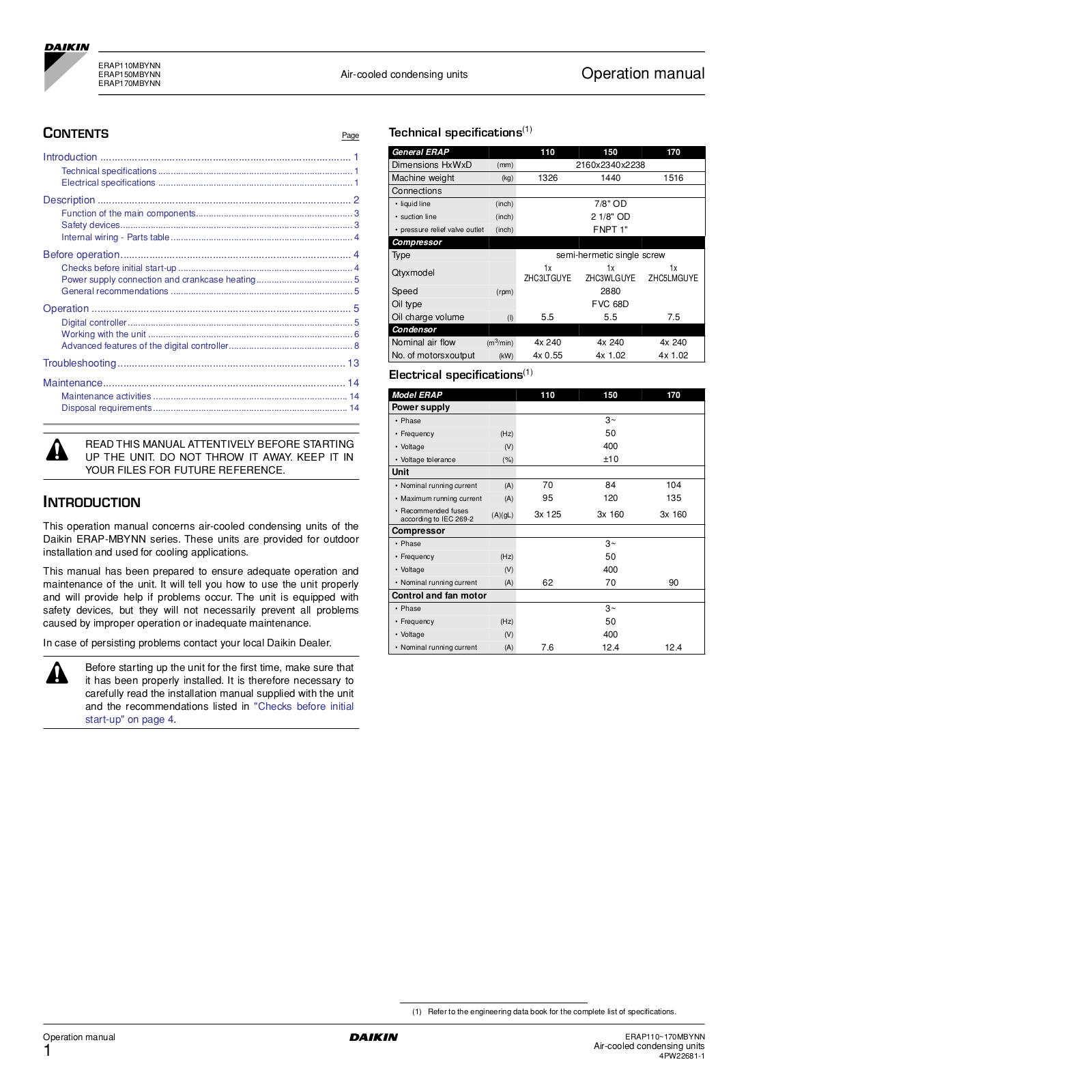
Daikin ERAP110MBYNN, ERAP170MBYNN, ERAP150MBYNN Operation manuals
...
Daikin Operation manuals
Download
Specifications and Main Features
Frequently Asked Questions
User Manual
Download
Loading...
+
12
hidden pages
Unhide
You need points to download manuals.
1 point = 1 manual.
You can buy points or you can get point for every manual you upload.
Buy points
Upload your manuals
 Loading...